GEI-77070 AND . com . com . ElectricalPartManuals Electric... · 35 3 GJ.rd:lei' An_.. • • St....
52
INSTRUCTIONS AND RENEWAL PARTS ·> :·:�-· ;i . . � ', MAG,NE -BLAST CIRCUIT,. BREAKERS Types AM 4.16 • 75 • 1 AM 4.16- 7SA · 1 AM 4.16·7SH · 1 with MS -9 Mechanism CONTENTS TRODUCTION ..••••..•...•.•..•.• 3 RECEIVG, HANDLG AND STORAGE ................ 3 INSTALLATION ..................... 3 DESCRIPTION OF OPERATION ..... .. ............ 4 ADJUSTMENTS ......... ............ 4 INSPECTION AND TEST .. . .. .... 9 MAINTENANCE .... . ..... ..... .... 10 RENEWAL PARTS . . .. ............ 17 MEDIUM VOLTAGE SWJTCHG£AR DEPARTMENT GENERAL. ELECTRIC PHILADELPHIA, PA. GEI-77070 B SUPERSEDES GEI-77070A www . ElectricalPartManuals . com www . ElectricalPartManuals . com
Transcript of GEI-77070 AND . com . com . ElectricalPartManuals Electric... · 35 3 GJ.rd:lei' An_.. • • St....

INSTRUCTIONS AND RENEWAL PARTS
·> :·:�-·
;i .... �',,
MAG,NE -BLAST CIRCUIT,. BREAKERS
Types AM 4.16 • 75 • 1 AM 4.16- 7SA · 1 AM 4.16·7SH · 1
with MS -9 Mechanism
CONTENTS
INTRODUCTION ..••••..•...•.•..•.• 3
RECEIVING, HANDLING AND STORAGE ................ 3
INSTALLATION ..................... 3
DESCRIPTION OF OPERATION . . .. . . . . ........... 4
ADJUSTMENTS ...... . . . .. . . ... . .... 4
INSPECTION AND TEST . . . . . .... 9
MAINTENANCE . . .. . . . . .. .... . .. . . 10
RENEWAL PARTS . . .......... .... 17
MEDIUM VOLTAGE SWJTCHG£AR DEPARTMENT
GENERAL. ELECTRIC PHILADELPHIA, PA.
GEI-77070 B SUPERSEDES GEI-77070A
www . El
ectric
alPar
tMan
uals
. com
www . El
ectric
alPar
tMan
uals
. com

www . El
ectric
alPar
tMan
uals
. com
www . El
ectric
alPar
tMan
uals
. com
GENERAL ELECTRIC INSTALLATION AND SERVICE ENGINEERING OFFICES FIELD SERVICE OFFICE CODE KEY
Mechanical & Nuclear Servl..ce Electncal & Electronic SerVlce Marine Service
FOR YOUR LASTING SATISfACTION . .• with tht- performance and availability of your Gen· erol Electric equipment, GE provides this nationwide network of field service offices, serving
utility, indultrial, transportation and marine users. Qualified field engineers provide instal· lotion, start-up, employee training, engineering maintenance and other services, throughout the productive life of the equipment. For full information, call your nearest Installation & Service Engineering office. X' Transportation
ALABAMA t Birmingham 35205 .. 2151 Highland Ave.
• t 1 Mobile 36609 . . . . 1111 3. Beltline Highway
ALASKA t Anchorage 99501.
ARIZONA
. 115 Whitney Rd.
• t PhoenLx 35012 . 3550 �-Central Ave. t T ucson 85716 . ....... 151 S. Tucson Blvd.
ARKANSAS t North Ltttle Rock 72119 ... 120 :'1-l:un St.
CA LIFORNIA • t L.Js Angeles 90054
t Palo Alto 94303
t Sacramento 95808. t San Di.ego 92103 .
San Francisco 94119 . Vernon 90058.
COLORADO
.212 :-i. Visnes ::3t.
360 San Antonio Rd. 2407 J St.
. . 2560 First Ave. 55 Hawthorne St.
. 3035 E. 46th St.
• t Denver 80206. . .... 201 University Blvd.
�C�\E::·:-:'--:.;� • t �,ler:rito:. .1)4SO
FLORIDA
l Prest1";10" Dr.
t JacksonVIlle 32203 . 4040 Woodcock Dr. . 4100 W. Flagler St.
2106 5. LOIS Ave . t r :\1iami 33134
.. t : Tampa 33609
GEORGIA • t t Atlanta 30309.
t t Savannah 3 1405
H.\",\'Ari " t :t Honolulu 96813 ..
ILL!:>OIS • T ! "( Chtcago 60680
• t
IOWA
E\�ansV1lle 47705 Ful.'t Wavne 46807 Indtanap�lis 46207
t Davenport 52805
. 1860 Peachtree Rd., �W . 5002 Paulsen St.
440 Coral St.
.840 S. Canal St.
2709 Washington Ave. 3606 S . Calhoun St.
3750 N. Mend ian St.
. . . P. 0. Box 630. 1039 State St.. Bettendorf
KENTt:CKY t LoutsVllle 40218 2300 Meadow Dr.
LOL'ISIA..'IA Baton Rouge 70803 ..... 8312 Flor:da Blvd. :-.<ew Orleans 70125 . 4 74 7 E .1rn.ut BJ·.-ct.
�1onroe 7 1201
\lARYLAND • t t Balttmare 21201.
�IASSACHUSETTS • T r Welles�ey 1)2131
�IICHIGA:-1 .. t t Detrmt 48202
Jackson 49201
�I]}; NESOTA
:;•�:::·: ':c �te: . .J.r·,· Dl·:-! .
. . 1028'S orth 6th St.
1 �. C1.J.r!es St.
...... 700 .\nto!�ette St. ... 2 10 \1; F::c:oklin .St.
t ! Dulurh 55d02 300 ·.v. :::3uoerwr St. .. T t Minneapolts 55416 . . . 1500 Ltlac
.Drt ve So
�IISSOCRI .. t Kansas City 64199.
'.iU>· �."\.,\.� 3utte 5:170�
:\'EBRA.SKA Om:lna �6 :G2
�EW JERSEY �·lillbun ,J7C'4l
):EW ":'ORK At!Jany 1220�
• t I Buffalo >t-20'5 r � ( �ew York 10022
Rochester 141304 Syrac,Jse I320j
:\OP.TH C.-\TIOL]};A
911 \lain St.
IS CompcttL·r Dr;•:e. West 025 DelJ.\\J.f-2 .-\ve.
64 l L exu-:r:ton Ave. 39 Ltst .\ve.
3532 ;J.mes St.
• t :r Charlotte 282J7 H l Pr:J\·�.j('nce Rd.
GHIO
Wtlnnr!�tton Re1gelv:o:Jd 28456.. ?.O.Box 186
Cmcwnan 45206. Cleveiand 44104 . Columbus 43229 Toledo 436013
Youngstown 44507
.. 2021 V1cton· Pr-\'.·\·.
1000 Lakes1de A ve . 1110 }.lvrse Rd.
3125 Dor.1:::las Rd, 2 72 Ind1ar:ola .-l,.se.
GENERAL ELECTRIC SERVICE SHOPS
OKLAHO�TA • t Oklahllma City 73106 ... 2000 Classen Bh•d.
Tulsa 74105 . . P. 0. Box 7646. Southside'::ita.
ORE GO!\ Eu�ene 97401.
* t ! Portland 97210. , .. 1170 Pearl St. 2929 ':\W 29th Ave.
PE!\:\'SYLVANIA \llent-0\\'n 18102 .
" T r Ph:ladelphta l 9 1G2 3 Penn Cen ter P!.ll.l • T P1ttsllur�h 15222 .... 300 6th A·:enue Bld,.:.
SOl'TH C:\HOLll\.\
TE'iXESSEE
TEXAS
l:TAH
Chattanooga 3 74 1 1
... 5800 Bldg, Eas{f:ate CEnter \lemplns 38130.. 33B5 .-\tnvavs Bl ·:d.
, ..
0.1l!J.s �:;222 dl()l :::it('r:-ln::;! � frt"\".' . .l\. £: P:-,�r� 7994'5 215 :-..;. Swn· ... n Fort \\-Clrth 7S102
;-hJ.::.ton 7�iJ2': San Ant..nw 7320-i.
-!.03 W ;)t".'e:-:.L'l St. .t2 :J i'LC:".:'.�· �.r. �
43-i ::) . :.Lun :;.t
VIR GI�L\ :\ewpurt !'\e\\'� 23601 '3 11 '.b::! .::t
T [ RtcnmomJ 23230. 1=,(..,-j '.'. L. \'\ :11·. Ho:I!l<;r..t 24Ul5 2•_,•)3 .� ! .! . . :L �·J.
\VA:3HI\'GT0:\ • t
WFST \'ll-H.;f):I.-\ (";J.rlt·.:,tr,L 2;)32"
3003 ·.\-' �� l- .j :, ._,, '!:: Jl S � \1 t L·:.c_ t:·
WHEN YOU SEED SERVICE . These GE Sen1.ce Shops '.nll rcpa1r. reconditiOn. and rebutld your electnc apparatus. The facll1tles a re availJ.ble
day J.nd mght, seven days a week. ft,r work 1n the shops or )Jl you r pre m -
tses. L.J.test lJ.r'!:urv metb:.�d� .lnd �enumt:· �iE rent·\�.d p.trts .1r.:· .;::.cct �r1 mJ.tnL.dn perfurmanCe ot yuur equipl-niO'nt. F ,r full Jniurm.l\i•ln a�JiJc:t ti·.r-�t
�erV1ces. contact .,:our nearest serncf' slLlJ; •r ,,t!e� �ff:·-·c
ALABAMA • • Birmingham 35211 . . 1500 �hms Ave. ,S. \V.
• Mobile 36609 721 Lakeside Dr.
ARIZONA • (Phoemxl Glendale 85019.4911 W. Colter St. e PhoenJ.X dSO 19 .... 3840 W. Clarendon St. • Tucson 85713 .... 2942 So. Palo Verde Ave.
CALIFORNIA e Los Angeles 90301 . . 6900 Stanford Ave. • 'Los Angeles! Anaheim 92805
3601 E. LaPalma Ave. (Los Angeles) Inglewood 90301
. . . . . . . . . 228 W. Florence :\ve. • Sacramento 95814 . . 99 :-l'o:rth 17th St.
ISan Francisco) Oakland 94608 1650 34th St.
COLORADO • � Denver 80205. 3353 L arimer St.
COS�ECTICCT • * rSouthlngton) Plantsvtlle 06479
370 .-\t·.-.·ater 3t.
FLORIDA JackSOm'llle 32203 . . . 2020 W. Beaver St.
• rMiamt) Hialeah 33010. 1062 East 28t.i St. • • Tampa 33601 . i9th & Grant 5ts
GEORGIA • Atlanta) Chamblee 30341
.. 5035 Peachtreelndustnal-Blvd. " Atlanta 2379 John Glenn Dr.
ILLINOIS e • Ch1cago 60638 ... 6045 S. Nottm�ham Ave.
IND IA.'<A
IOWA
e Evansville 4 7 711 • Ft. Wayne 4 6803 e Hammond 46320 .
rndianapolis 46222
401 N. Congress Ave. 1731 Edsall Ave.
1138 164th Place 1740 W. Vermont St.
• !Davenport) Bettendorf 52722 . 1025 State St.
KENTUCKY • LouiSVllle 40209 .... 3900 Crlttenden Drive
LOUISIA.'iA • Batun RouL:e 70814 . . . 10955 :Oorth Dual St.
• � �ew Orleans �0114 . . 1115 De:\rm.ts St.
;o.L\RYLA:-\0 • • Baltimore 21230.
:\L\SSACHCSETTS Boston1 \!r:�df·Jrcl 02155
. 3960 \Iysttc \·,,;:'=':· Pkwy
�11CHIGAN • • ..:. 1Qetro1t1 Rtvervle'". 120'75 Kn.use .-\v�:.
• Flint 48505 .. 150G E. C..lf]F:nter Rd.
\!Di:-IESOT.4. • Duluth 55807 50th Ave.\\ &: Stl,,lttS
• • \1mneapoh� 35430 2.025 49th .-\:.e.
:'1-fiSSOL'RI • • Kansas c.r .. · -34120. 35�3 GJ.rd:lei' An_..
11:5 ::.1.st Hd. • • St. Lou1.s r'i3!l0
�EW JEHSEY • ';e\\ !lr,m,;·,q;K 'J8902 3 Lt·,:··:nce St.
;.,"£\\- �.rE.X"lCO • --\�b..Jquerc!Clt' �7109
;.,"EW YORK • AlbJ.nv 12�05 1097 Cd':r.,i .--\;·e.
B�.lifai•J ;'Jr.a·.vandJ. 14150 175 \Liens RJ • Lo115 island; Old Bethpage 11604
183 Bethpage-S•,.,:eet Hn;l,;w P.d. • �ew Y<;rk C:tyl :Sorth Bersen . �. J. J7012
6001 Tun:1elie .-\ve. !'<ew York C:tv : C!1fton. :S. J. 07012 ·
9 Bnghton Rd. Schenectadv 12305 1 :'{:ver Rd.
• Syracw.se 132Cd. 1015 E. Htawatr:a Bl\·d.
�:ORTH CAROL� A Charlotte 28208 2328 Tt.nft Rd.
OHIO • Akron . Cantun1 44 720
... 7900 \-Vh1.pple .-\ve. �. W. C:nc;nnatl 45202 . 444 West 3rd St.
• • ' Cleveland 44125 . . .. . , 44i7 East 49th St. • Columbus 43229. . .... 6660 Huntl ey Rd.
Toledo 43605 405 Dear corn Ave. • Younl.!;stown 44507 . . . , 2i2 E. rnd1ar.oia Ave.
OKLAH0\1.-\ • Tui::..1 i'4H:S �·?:21J '5.
ORE GO'-: • Eu!.',ene )7-.tu2
e • P(JI't�.lntl :J72 ltJ i70 ',\ ·1::. .!0 ;:;t,
�':':.!7 \'',\' �v'L'1 :he.
PE:;:\2Y!.. \'.\.\"I.\ • .'-l.l!cntv.,,n lol:.,3 r�t_,3 E. ii:._ni.J.r:a St .
o�:!'t\•.an· \'.ti:H·!CfH·rT'; Hill . '\ . l.. Jd034 . iDO E. '.ial·lti!ll Ptkc
.:uim�t:. ',\ f1 15;.:02 ':!-! 1 O,L,.: jt. • Ph,:.tdt:'lpma l'Jl.H 1040 E:1st Ene \·:e.
• • Plltsbur�h· \Vest \o'hff!:n 15122
SOlTH C.\POLI:-..\ • Ch.tl';t'St'lll >;.;n, Charh.'str,n 2:141)1
TFX .. \ES.)EE • KJJ, :xn! c J'7·J14
2 ; .,_, '}. �t .
:J·.·
'iL'.tJJ.: l'.t -:-:�.Fi l·PO ·.v. c--.�rrl:J:,. Jr. C:or:sn �d40l i.l.":i ',1• <•:,! )t.
l'TAH
�323.') e ; f,L>Sit <tl ';'':'IJJ>�
i�(_':_j;St_;n 77�J')
Sa:t Like Cit; -HllO
VIRGI"l.\ • • R1chm ond 23224
• Ro:tr.vke: 2-1013
WASHINGTO'i • � Seat tle 98124
• :=�lOkJ.ne J92 :.1
\VEST �:IRGISIA
.no::: '.i.wc r ·.\ .r. J.)J.f ;!.tr'.t··: \\,::o "Ur
·��lJ':' i!.tr ' .. i\ Dr. 704 :i .;.;!tr:::'tJr. ':it.
301 5. �th '.\'bt St.
1-ttJJ !J•.•;r;l. r: .. \•:e. 1004 Htver :·\H:. SE
. 3422 Fcrst .-\ve .. ::out� £_ 4.2-23 \hSSl'Jn .=:t.
• • Charlestvn 2'5328 .. 306 \!:l.cCorkle .·\';<;,. 3E
WJSCO�si:-; • AppletPn l .\tenasha 54910 1�25 R.1c:ne St. • \ttlw::J.Ukee 5320i 235 \\' Ok!a:1(�1J .\ve.
e Electrical/�echanical Sen,ce Shop • Instrumentation Shop - Spec1al :.-Ianufacturtr.>! :::ihup
2-71 GENERAL ELECTRIC COMPANY, PHILADELPHIA, PA. www . El
ectric
alPar
tMan
uals
. com
www . El
ectric
alPar
tMan
uals
. com

..
www . El
ectric
alPar
tMan
uals
. com
www . El
ectric
alPar
tMan
uals
. com

"' .... "' 00 "' 0 00
�
.. ., > 3
MAGNE-BLAST CIRCUIT BREAKER TYPES AM 4.16-75-1 AND AM 4.16-75A-1
VJITH MS-9 MECHANISM
The Magne-blast Circuit Breaker is the removable interrupting element for use in vertical-lift metal-clad switchgear, to provide reliable control and protection of power systems.
The �lagne-blast Circ'..lit Breaker operates on the principle that an arc can be interrupted in air by sufficiently elongating and cooling it. This is accomplished by means of a strong magnetic field that
INTRODUCTION
lengthens the arc and forces it into intimate contact with cool dielectric material.
Refer to the breaker nameplate for the complete rating information of any particular breaker. The short circuit conditions to be imposea on iile bre<W{er must not exceed its rating, nor should it be called upon to operate at voltages or currents greater than those given on the nameplate. Since this book is written to cover several ratings of breakers that are of the same general
design, all instructions will be of a general character and all illustrations will be typical, unless otherwise specified.
PROPER INSTALLATION AND MAINTENANCE ARE NECE.:iSARY TO INSliRE CONTINUED SATISFACTORY OPERATION OF THE BREAKER. The following instructions will provide information for placing the magne-blast breaker in service and for maintaining satisfactory operation.
RECEIVING, HANDLING AND STORAGE
RECEIVING AND HANDLING
Each breaker is carefully inspected and packed by workmen experienced in the proper handling and packing of electrical equipment. Imrr,ediately upon receipt of the circuit breaker, an examination should be made for any damage sustained in transit. If injury or rough handling is evident, a damage claim should be filed immediately with the transportation company and the nearest General Electric Sales Office should be notified.
It is expected that due care will be exercised during the unpacking and installation of the breaker so that no damage will occur from careless or rough handling, or from exposure to moisture or dirt. A nail puller should be used to open the crates, and care should b& exercised to prevent tools from striking either the crate or any part of the
Remove box barrier and make a visual inspection to ascertain that the breaker is in satisfactory condition. Check all bearing surfaces of the mechanism for lubrication. Refer to the section on LUBRICATION (page 11).
Operate breaker manu;,tl!Y.. .u�ing the maintenance cj_g_sj_I}g__<t!l'-:ice provided with the breaker. During the closing operation, cnecK1Cl'insure that the mechanism and breaker does not stick or bind during the entire stroke, that it latches securely in the closed position, and that it trips freely when the manual trip plunger is operated. The breaker sho':lt�.-�! .. be_ operated elec-
breaker. Loose parts associated with the breaker are always included in the same crate. Check all parts against the packing list to be sure that no parts have been overlooked.
STORAGE
It is recommended that the breaker be put into service immediately in its permanent" location. If this is not possible, the following precautions must be taken to insure the proper storage of the breaker:
1. The breaker should be carefully protected against condensation, preferably by storing it in a warm dry room, since water absorption has an adverse effect on the insulation parts. C ircuit breakers for outdoor metal-clad switchgear should be stored in the equipment only when power is available and the heaters
INSTALLATION
trically until it has been .oee.ra,!_eg_rnal}ually to 1nsure th1s freedom qf action.
The following adjustments should be checked at this point.
a. Primary contact wipe (page 5).
b. Primary contact gap (page 5).
c. Prop clearance (page 5) .
Att.�c_ll test cou.!iler to circl!it bre�.!s_e]" and operateefecfncally severartlmes. The control voltage should be checked at the breaker as indicated under CONTROL POWER CHECK (page 10).
are in operation to prevent condensation.
2. The breaker should be stored in a clean location, free from corrosive gases or fumes; particular care should be taken to protect the equipment from moisture and cement dust, as this combination has a very corrosive effect on many parts.
3. Machined parts of the operating mechanism, etc., should be coated with a heavy oil or grease to prevent rusting.
If the breaker is stored for any length of time, it should be inspected periodically to see that rusting ha_s not started and to insure good mechanical condition. Should the breaker be stored under unfavorable atmospheric conditions, steps should be taken to dry out the breaker before it is placed in service.
Remove tEl�LG.Ou.PJ�r __ a!1d_r:ep.lace box barrier.
If breaker has been stored for a long period of time, it is recommended that the insulation be checked with the standard 60 cycle high potential test --- see INSULATION TEST (page 11).
Lubricate the silver portion of the primary disconnect studs by rubbing a small amount of contact lubricant D50H47 to form a thin coating on the ball contact.
Refer to instruction book GEH-1802 for final instructions before inserting the breaker into the metal-clad unit.
These instructions do not purport to cover all details or variations in equipment nor to provide for every pouible contingency to be met in connection with installation, operation or maintenance. Should further information be desired or should particular problems arise which are not covered sufficiently for the purchaser's purposes, the maHer should be referred to the Genera/ Electric Company.
3 www . El
ectric
alPar
tMan
uals
. com
www . El
ectric
alPar
tMan
uals
. com

www . El
ectric
alPar
tMan
uals
. com
www . El
ectric
alPar
tMan
uals
. com

GEI-77070 Magne-blast Circuit Breaker Type AM 4.16-75
DESCRIPTION OF OPERATION
The magne-blast breaker is composed of two major parts, the breaker element Fig. 9 and the operating mechanism Figs. 7 and 8. The breaker element comprises three similar pole units, each pole unit consisting of main and arcing contacts, an interrupter, and an enclosing box barrier that segregates the interrupting units from each other to provide insulation between phases as well as from each phase to ground. The primary connections to the associated metal-clad equipment are made through the primary disconnect studs.
The MS-9 operating mechanism shown in Fig. 7 is of the solenoid type designed to give high speed closing and opening. The closing operation is controlled by the control relay. The control relay scheme permits trip-free operation (tripping the breaker at any time during the closing operation)1 and prevents solenoid pumping (reclosing} after a trip-free operation. For a-c closing operation, rectifiers mounted elsewhere in the metal-clad unit are used to supply the direct current on which the closing coil operates. The breaker can be opened electrically, by remote control, or manually, by means of the manual trip device. All secondary connections from the breaker to the metal-clad unit are made through the coupler.
A positive interlock and interlock switch is provided between the breaker and metalclad unit to prevent the raising or lowering of the breaker in the unit while in the closed position and to prevent a closing operation when the breaker is not in either the fully raised or lowered position. A plunger type interlock can also be provided.
OPENING OPERATION
REFER TO FIGS. 8 & 9
An electrical opening operation is initiated by energizing the trip coil. Th�s is accomplished either by actuating the opening control switch on the metal-clad unit or by a combination of relays and current devices used to detect a fault on the load side of the breaker. By ener-
DO NOT WORK ON EITHER THE BREAKER OR THE MECHANISM WHILE IN THE CLOSED POSITION U NLESS THE PROP AND TRIP LATCH ItA VE BEEN SECURELY WffiED OR BLOCKED TO PREVENT ACCIDENTAL TRIPPING.
A maintenance operating handle is provided for operation of the breaker during these adjustment checks. �aectric;.�l op�a!!Q!L!!!!i.�.!._nQLh!! __ �tt�!P..P.te� _until the bre��_!!.r_h_as __ tl_�?_e_LJ._QP�J"�te_d_.Jnanually through it�_<eQ.mplete_ ::;tx:9X� ::;ey_e_ral times and final inspection has. b���-.£9.'E.P.��!�d.
All adjustments should be checked during periodic inspections and whenever it becomes necessary to repair or replace parts that have become worn or defective while in service.
4
gizing the trip coil, the trip plunger rotates the trip latch, causing the operating mechanism linkage to collapse. The energy stored in the opening spring is thus released, opening the breaker. During this operation, the trip coil circuit is de-energized, and upon completion of the opening operation, the operating mechanism is returned to its normal position, ready for closing.
As the breaker opens, the main contacts part first, shunting the current through the arcing contacts. An arc forms as the arcing contacts part. As the movable arcing contact is withdrawn through the slot in the arc runner, the upper end of the arc is transferred to the upper arc runner. To assist the interruption at this point, a stream of air is emitted from the booster tube and forces the arc onto the lower arc runner. Establishment of the arc on the runners automatically inserts the blowout coil into the circuit, introducing a magnetic field between the pole pieces which tends to draw the arc away from the arcing contacts. At the same time, the arc is being forced into the arc chute which is composed of a series of gradually interleaving insulating fins. These fins, which project alternately from the two opposite inner surfaces of the chute, elongate the arc into a gradually deepening serpentine path, so that the electrical resistance in the path of the arc is rapidly increased and the heat from the arc is absorbed. The increased resistance reduces both the magnitude and the phase angle of the current, and at an early current zero the arc path is so long and the gases produced by the arc so cooled that the arc cannot re-establish itself1 and interruption occurs.
Manual tripping follows the same procedure except that instead of energizing the trip circuit, the manual trip button is used.
CLOSING OPERATION
REFER TO FIGS. 8 & 9
The closing operation of the breaker is primarily controlled by the control
ADJUSTMENTS
PRIMARY CONTACTS
REFER TO FIGS. 1 AND 9
The primary contacts, Fig. 1, can be adjusted by means of the operating rod adjusting screw. To adjust, remove the pin fastening the adjusting screw to the mechanism crank and push the contact blade far enough closed so the adjusting screw can be turned. To increase the primary contact travel, turn the adjusting screw in the direction to lengthen the rod, and to decrease the primary contact travel, turn the screw to shorten the rod (1/2 turn gives approximately 1/32" change in contact travel). Reconnect the operating rod to the crank, and close the breaker manually to check the adjustment.
device, Figs. 5 and 6 mounted on the breaker frame. The closing sequence is initiated from a control switch mounted on the door of the metal-clad unit or at a remote operating station. Operation of the closing control switch energizes the pick-up coils of the control relay. As the control relay closes, seal-in contacts shunt the closing control switch to allow the opening of the closing control switch contads without affecting the o·:erall closing operation. This type of arrangement assures complete closing of the breaker with only momentary contact of the closing control switch.
. Operation of the control relay energizes the breaker closing coil by closing the main control relay contacts. Once the control rela_y contacts are picked up, they are electncally held in the closed p_osit�on until the breaker closing operahan 1s completed. Energizing the breaker closing coil raises the armature which in turn lifts the closing roller by action of the solenoid plunger rod. This motion is transmitted through the mechanism linkage and rotates the main crank closing the breaker contacts. As the armature reaches the end of its travel, the prop rotates beneath the pin latching the breaker in the closed position. During the closing operation the opening spring is compressed in readi�ess for an opening operation. Air trapped above the armature acts as a dash pot to absorb the energy of the mechanism as it approaches the end of its stroke.
TRIP FREE OPERATION
REFER TO FIG. 8
. If the trip coil circuit is energized whtle the . breaker is closing, the trip plunger Will force the trip latch away from the trip roller causing the mechanism linkage to trip free and the breaker to re-open. The closing armature completes its closing stroke, but the closing coil is de-energized at the end of the stroke, and the armature is returned to its original position by gravity.
After the above adjustment has been made, the travel of the contact surface of the prim.>ry contact should be measured on a manual closing operation. The primary contact wipe should be 1/8" + 1/16" -0.
ARCING CONTACT WIPE Refer to Fig. 1. Close the breaker
until the arcing contacts just touch. This can be determined with the use of a circuit continuity tester such as a light indication or bell set. In this position, the gap between the stationary primary contacts and the movable primary contact should be 7/32" to 9/32". To adjust, the following procedure should be followed:
(a) Loosen the lock nut on the arcing contact stop bolt.
/'" 1_
www . El
ectric
alPar
tMan
uals
. com
www . El
ectric
alPar
tMan
uals
. com

www . El
ectric
alPar
tMan
uals
. com
www . El
ectric
alPar
tMan
uals
. com
,._ "' <0 "' ... <0
... ,._ "' <0 "' ... <0 I ""
"' 0,
u..
(b) With Allen wrench, turn the stop bolt until the arcing contacts just touch when the gap at the primary contact is 7/32" to 9/32".
(c) Lock the stop bolt in position with the locknut, and close the breaker manually to check the adjustment.
ARCINGCONTAC T CLEARANCE
REFER TO FIG. 1
The movable arcing contact should be centered between the arcing plates located on the arc runner. This is accomplished by moving the arc chute aideways to the correct position. The mounting support has an oversize hole to permit adjustment.
CONTAC T GAP
REFER TO FIG. 6
With the breaker tripped from the closed position, the minimum distance from the primary contact fingers to the surface of the primary contact on the movable contact blade should be 4-1/16" to 4-1/4". To adjust for these conditions, turn the stop nut (21), Fig. 8, to increase or decrease the contact gap. After making the adjustment, close and trip the breaker manually and measure the gap once more.
NOTE: A change in this adjustment may require a change in the adjustment of the plunger rod (17), Fig. 8, in the mechanism as described later.
LATCH WIPE
REFER TO FIG. 2
The wipe of the latch on the trip roller should be from 1/8" to 1/4". This can be determined easily by putting a film of grease on the latch, closing the breaker part way, and tripping. To adjust, add or remove washers under the head of the stop bolt located near the top of the latch on the trip coil frame.
PROP
Magne-blast Circuit B reaker Type AM 4.16-75 GEI-77070
PRIMARY CONTACT FINGER
Fig. I Contact Assembly
PROP CLEARANCE
REFER TO FIG. 2
With the breaker closed as far as possible with the manual handle, the clearance of the pin through the closing roller over the prop should be 1/32" to 3/32" with a maximum variance of 1/32" between sides. This can be adjusted by dropping the closing armature (18), Fig. 8, and closing plunger rod (17), Fig. 8, and screwing the rod into or out of the armature. To do this turn the breaker on its back as shown in Fig. 15 and disassemble the wheel base and solenoid pot assembly as described in replacement of a closing coil on page 15.
CLOSING R O LL ER
TRIP LATCH
TRIP ROLLER
PROP
PLUNGER
NOTE: Two set screws are used to lock the plunger rod in position in the armature. If the rod adjustment is changed the rod must be spotted in the correct position and the set screws replaced.
LATCH CLEARANCE
REFER TO FIG. 3
The clearance between the trip latch and roller with the breaker open should be approximately 1/32" to 1/16". This can be adjusted by means of the stop bolt (12), Fig. 7, in. the front of the mechanism frame near the bottom. The lock nut should be fastened securely if any adjustment has been made.
OPENING SPRING
TRIP LATCH
=�--,£--CLOSING ROLLER ��==��---PLUNGER
Fig, 2 Mechanism Linkage Closed Position Fig. 3 Mechanism Linkage Open Position
5 www . El
ectric
alPar
tMan
uals
. com
www . El
ectric
alPar
tMan
uals
. com

www . El
ectric
alPar
tMan
uals
. com
www . El
ectric
alPar
tMan
uals
. com

GEI-77070 Magne-blast Circuit Breaker Type AM 4.16-75
PLUNGER CLEARANCE
REFER TO FIGS. 3 AND a With the breaker in the open position
there should be at least 1/8" clearance between the plunger and closing roller. To increase this clearance, the brackets (22), Fig. a should be lowered by placing a shim between the bracket and the bottom plate of the solenoid housing,
I NTERLOCK S WITCH WIPE
REFER TO FIG. 4
Rotate the interlock shaft manually counter clockwise. The point at which the contacts break can be determined with a circuit continuity tester such as a light indicator or bell set. To adjust interlock switch (1), Fig. 4 move switch bracket (6), The roller and crank on the inter lock switch should have 1/32" to 1/16" overtravel after final adjustment.
CUT-OFF SWITCH ADJUSTMENT
REFER TO FIGS. 5 AND 5A
Using a manual closing handle, close the breaker as far as possible. (So that the prop pin is over the prop and not resting on the prop). At this point the "S" shaped striker rod should be resting against the striker rod guide bracket (3), Fig. 5 as shown in Fig. 5A.
Adjust cut-off switch striker rod (2), Fig. 5 so that it is against the switch roller (7), Fig. 5 and so that the switch roller has an additional overtravel of 1/32".
CONTROL RELAY ADJUSTMENT
REFER TO FIGS. 5 AND 6
TYPE HJA RELAY
The relays have been adjusted at the factory to pick up at 61 per cent of rating for d-e relays and 80 per cent for a-c relays. The settings of the various contact gaps and wipes should not be disturbed.
If it is necessary to rea:djust the relays the following points should be observed. The wipe of the main contacts should be 1/8" measured at the top edge of the pole piece while that of the auxiliary should be 1/8" when measured at the rear edge of the armature stops.
If the setting of the control spring must be changed for any reason, care must be taken during the readjustment to see that the control spring is not weakened to the point of permitting the minimum of wipe to exist at the normally closed auxiliary interlock contacts.
The relay contains a permanent magnet which has numbers stamped on one end only. The magnet is oriented properly in the relay when it is positioned so that the numbers are located on the left hand side. (Facing relay.)
On d-e operated relays, a visible check should be made to see that the arc being interrupted by the relay is directed through the arc chute and not back over the relay
6
I 4 1. Positive Interloc k Switc h
2. Inter loc k Arm 3. Switc h Roller 4. Switch Actuator Cam 5. Interloc k Shaft 6. Switc h Mounting Bracket 7. Interloc k Indexing Roller
F i g. � Pos i t i ve Interlock Swi tch
1. Cut·off Switch 2. Cut-off Switch Striker Rod 3. Striker Rod Guide Brac ket 4. Striker Rod .\i j ustment Nut 5. Contr ol Relay (HJA Relay) 6. Contr ol Relay Mounting Plate
Fig, 5 Side V i ew of Control Relay and Cut-off Sw i tch Assem bly
<D ..... "' � 0 co
www . El
ectric
alPar
tMan
uals
. com
www . El
ectric
alPar
tMan
uals
. com

www . El
ectric
alPar
tMan
uals
. com
www . El
ectric
alPar
tMan
uals
. com

I Mnt OVE� iltt'Wi.J.. i !z �# �W•TCH ;, 1 - e"LI..4«
fr�¢ . .
_ __ ] __ ,\ i i '�cs!J vo� I
sreuc£/l Zoo €.£�T� ,.:,�,.,,,.,;�r !JR,..c<e.r n�-�ftl �045w 14/1P�
� 5 .5�< ;;,;:� <;;,,:�;;;
I
.
Fig. SA
coil. If the arc is not being directed through the arc chute the following checks should be made:
1. Check the polarity of the control power.
2. Check the control device to see if the magnet is assembled properly. (As described previously.)
3. Check to see that the closing coil leads have been assembled properly. (Refer to the section on repair and replacement of closing coil).
TYPE HMA RELAY
The relays are properly adjusted at the factory for operation when mounted on a vertical surface. Relays for d-e service are adjusted to pick up at 60 per cent of their rating when cold and 80 per cent when hot. Relays for a-c service are adjusted to pick up to 80 per cent of their rating.
Normally it should not be necessary to make any further changes in these adjustments. If, however, the correct pickup is not realized, adjustments can be made by changing the tension of the armature restraining spring. This is accomplished by bending the projecting spring holder on the armature stop. The spring tension should not be so low that the back wipe is sacrificed.
AUXILIARY SWITCH
The auxiliary switch (7) is mounted on the right side of the operating mechanism Fig. 7. The shaft of the position indicator operates the auxiliary switch shaft which opens and closes the "a" and "b" contacts. (The "a" contacts are open when the breaker is open and the "b" contacts are open when the breaker is closed.)
Magne-blast Circuit Breaker Type AM 4. 16-75 GEI-77070
1. Front Bushing llo Front Vertical Barrier 2. Rear Bushing 12o Breaker Handle 3o Horizontal Barriers 13o Secondary Couplers 4o Arc Omte Support Bolt 14o Manual Trip Button 5. Stationary Arcing Contact 1So Connecting Rod 6o Stationary Primary Contact l6o Control Device (liMA Relay) 7 0 Movable Primary Contact 8o Movable Arcing Contact 9o Arc Chute Support Bracket
100 Booster
1. Front BUsh>�� 2o Washer 3o Contact Ar"' 4o Bearing So Support Asmo 6o Screw 7. Cotter Pin 8o Nut 9o Spring
Cylinder
Fig.
3 4
5
6
17. Removable Manual Operating 18 0 Operai:ing �dechanism 19. Insulating 3ase 200 Arc Chute Assembly
Partial Side Yiew of Breaker
2
4
7
8
9
CONTACT 3L-4DE HINGE Fig. 6 Sec. 'U"
Handle
7
' '
www . El
ectric
alPar
tMan
uals
. com
www . El
ectric
alPar
tMan
uals
. com

www . El
ectric
alPar
tMan
uals
. com
www . El
ectric
alPar
tMan
uals
. com

GEI-77070 Magne-blast Circuit Breaker Type AM 4.16-75
1. 2. 3. 4. 5. 6. 7.
Secondary Coupler 8. Positive Interlock Ann Position Indicator 9. Control Relay Operation Counter 10. Closing Solenoid Manual Trip 11. Control Relay (HJA) Opening Spring Unit 12. Stop Bolt Breaker Handle 13. Closing Coil Leads Auxiliary Switch
Fig. 7 MS-9 Operating �echanism
7
6
19----\
20 3-------�t�� 4---------��
22
1. Main Operating Shaft 2. Main Crank 3. Trip Latch Shaft 4. Trip Latch S. Trip Roller 6. Operat ions Counter 7. Position Indicator 8. Upper Spring Support 9. Adjustable Spring Stud
10. Prop Rest Pin 11. Lower Spring Support
...... -----9 .H-c==----21
---12 �c�---;- 11
2
�7--1'--- I \.lill...t::::=------+--1,;=---1 0
I.
• .ar.I!S�!LA:.Q'
12. Opening Spring 13. Impact Shim 14. Closing Roller 15. Prop 16. Closing Coil 17. Closing Plunger Rod 18. Closing Armature 19. Trip Coil 20. Manual Trip Button 21. Mechanism Stop Nut 22. Bracket
Fig. 8 Type MS-9 So l enoid Operating Mechanism
AUXILIARY DEVICES
LATCH CHECKING SWITCH WIPE
REFER TO FIG. 11
enct of the reset stroke of the tripping latch. The point at which the switch contacts "make" may be adjusted by adding or removing shims.
IMPACT CURRENT TRIP, CAPACITOR TRIP AND UNDERVOLTAGE TRIP
DEVICES REFER TO FIG. 12
The latch checking switch is used to insure that the mechanism latch has been reset after a tripping operation. The latch checking switching contacts are connected in the control circuits in the metal-clad unit to prevent the closing coil from being energ;ized until the latch is reset. The contacts in the switch should "make" at the
PLUNGER INTERLOCK
Refer to Fig. 9. With the breaker in the closed position, the vertical distance from the top of the interlock bolt to the top of the breaker frame should be 5-5/8" + 1/16" -0. To change this adjustment add or remove washers.
When these devices are furnished with the breaker, the wipe of the impact current trip latch should be 1/32" to 1/16". This can be adjusted by the use of the small adjusting screw located behind and near the right end of the current trip mountin� bracket. Also, the adjusting screw (14) should be set 1/16" below the pin (12). This is to prevent the cam latch (3) from going over center.
8
� .... .... "' "" ('oj 0 ""
"" 0 .., ...., "" "" <D
""
.;. ...
www . El
ectric
alPar
tMan
uals
. com
www . El
ectric
alPar
tMan
uals
. com

www . El
ectric
alPar
tMan
uals
. com
www . El
ectric
alPar
tMan
uals
. com

For ease in reviewing the adjustments the following are recapitulated:
a. Primary contact wipe: 1/8" + 1/16" - o.
b. Arcing contact wipe: 7/32" to 9/32".
c. Primary contact gap: 4-1/6" to 4-1/4".
d. Trip latch wipe: 1/8" to 1/ 4".
e. Prop clearance: 1, 32" to 3, 32" with a maximum variance of li 32".
f. Trip latch clearance: 1/32" to 1/16"
g. Solenoid plunger clearance: 1/8" or greater.
h. Impact trip wipe: 1/32" to 1/16".
j. Impact cam latch clearance: 1/16".
k. Interlock switch: 1/32" to 1/16" overtravel.
0. 1. Cut-off switch overtravel: ... 1/32" to 1/16".
m. Plunger interlock: 5-1/8" + 1/16" - 0.
Check all nuts, bolts, screws, and cotter pins to make certain that they are properly tightened.
Magne-blast Circuit Breaker Type AM 4.16-75 GEI-77070
INSPECTION AND TEST
breaker when the control voltage drops below 40 to 60% of rated voltage, and it should pick-up at 80% of the control voltage or less. An adjustment plate is provided on the front of the undervoltage trip device as an aid in obtaining the desired setting.
NOTE: When checking the pick-up value of the undervoltage device, apply a voltage equal to 80% of normal control voltage to the undervoltage device coil. The device should pick up at this value. Do not increase the ·1oltage gradually on this coil as it will overheat the coil, producing a
false reading, and may damage the coil if excessive overheating occurs.
OPENING AND CLOSING SPEED
The closing speed of the arcing contact should be 12 to 16 feet per second with rated closed circuit voltage at the closing coil terminals. These speeds represent the average speed of the movable arcing contact from a point 1" before the tip is tangent to the lower surface of the upper arc runner transfer lugs to the tangent position.
Inspect all wiring. Check all terminals, screws, and connections and test the cir- ��---ft---.... cuits for possible short circuits or grounds.
See that all bearing surfaces of the mechanism have been lubricated. Refer to the section on LUBRICATION.
Operate the breaker slowly with the maintenance closing handle and note that there is no excessive binding or friction and that the breaker can be moved to. the fully opened and fully closed positions.
See that any place where the surface of the paint has been damaged is repainted immediately.
Check the operating voltage for both the closing coil and trip coil to determine if, with line drop, it is within the limits specified on the nameplate. In the case of a rectifier operated mechanism, the d-e voltage across the coil terminals with full closing coil current flowing should be 105-110 volts. (For applications of repetitive operations, the d-e voltage across the closing coil should not exceed 110 volts.) Refer to section on CONTROL POWER CHECK.
AUXILIARY DEVICES
On breakers that are equipped with auxiliary devices such as current trip, undervoltage trip or capacitor trip, the device should be checked for proper electrical operation. The current trip device should trip the breaker at 3 amperes. The undervoltage device should trip the
1. Front Bushing 8. Box Barrier 2. Horizontal Barrier 9. Breaker Frame 3. Trip Coil 10. Box Barrier Locking Plate 4. Operating Mechanism 11. Plunger Interlock 5. Front Vertical Barrier 12. Secondary Coupler 6. Arc Chute Assembly 13. Manual Trip Button 7. Rear Bus hing 14. Closing Coil
15. Arc Chute Mounting Support
F i g. 9 Side V i ew AM-�.16-75-1 Breaker with MS-9 �echan i sm
9 www . El
ectric
alPar
tMan
uals
. com
www . El
ectric
alPar
tMan
uals
. com

www . El
ectric
alPar
tMan
uals
. com
www . El
ectric
alPar
tMan
uals
. com

I l ·' I
GEI-77070 Magne-blast Circuit Breaker Type AM 4.16-75
The opening speed of the arcing contact should be 12 to 16 feet per second at rated control voltage. This speed represents the average speed over 3" from the point when the tip on the movable arcing contact is tangent to the lower surface of the upper runner transfer lug.
CONTROL POWER CHECK
After the breaker has been closed anci opened slowly severaCff!!ies-�-H? the maintenance operahng han�an?llie_!!l_�chanism _ a_dl��t!!l_e!l§>,. .£��S.K�"JI���nbed aqove, the operatmg voltages sliould be checked at the closing coil and trip coil terminals. For electrical operation of the breaker, the control power may be either an alternating or direct current source. The operating ranges for the closing and tripping voltages are given on the breaker nameplate. Ordinarily, standard ranges apply which are as follows:
NOMINAL CLOSING TRIPPING VOLTAGE RANGE RANGE 125v d-e 90-130v d-e 70-140v d-e 250v d-e 180-260v d-e 140-280v d-e 230v a-c 190-250v a-c 190-250v a-c
NOTE: Where repetitive operation is required from a direct current source, the closed circuit voltage at the closing coil should not exceed 115v d-e and 230v d-e
at the nominal voltages of 125v d-e and 250v d-e respectively.
To check the d-e voltage at the closing coil terminals, proceed as follows:
Close the_ bre_¥et_!>y _,r!laQ\l�.lly _pperatii!!Lihe comro[F�@y,_fjg .. _5_and 6. Hold the contacts in the closed position and read the d-e voltage at the closing coil terminals. To de-energize the circuit release the control device.
If the closed circuit voltage at the terminals of the closing coil does not fall within the specified range on d-e operated breakers, check the voltage at the source of power and the line drop between the power source and the breaker.
For a-c operation a germanium (colorblack, flanged base) or a silicon (colorblue, hex base) rectifier bridge assembly mounted elsewhere in the metal-clad unit is used. These rectifiers are of the buttontype and are hermetically sealed units. They have been tested and the resistor has been set to 2 ohms at the factory. Unlike rectifiers of previous design the output of the germanium or silicon unit is affected very little by ambient temperature changes and it should not be necessary to disturb the factory setting.
DO NOT MAINTAIN VOLTAGE ON THE CLOSING COIL ANY LONGER THAN
MAINTENANCE
fine file or sandpaper, the arc chutes can be removed as described under REPLACEMENT OF PARTS.
ARC CHUTE
REFER TO FIG. 14
Dependable service and safer power equipment are contingent upon the unfailing performance of the power circuit breaker. To maintain such service, it is recommended that a definite inspection and maintenance schedule be set up and followed, as serious shutdowns can often be avoided by locating potential sources of trouble in an early stage. A periodic lubrication of parts subject to wear is also vitally important If the arc chutes are removed for for the successful operation of the breaker. contact maintenance, and are for any reason
\ disassembled for inspection, the following BEFORE ANY MAINTENANCE WORK \ points should be noted:
IS PERFORMED, MAKE CERTAIN THAT ALL CONTROL CIRCUITS ARE DE-ENER- \ 1. Scale formed over the surface of GIZED AND THAT THE BREAKER IS the chute must not be removed REMOVED FROM THE METAL-CLAD but loose particles collected in the UNIT. DO NOT WORK ON THE BREAKER muffler should be blown out. OR MECHANISM WHILE IN THE CLOSED POSITION UNLESS THE PROP AND TRIP LATCH HAVE BEEN SECURELY WIRED OR BLOCKED TO PREVENT ACCIDENTAL TRIPPING.
PERIODIC INSPECTION
At this time a thorough inspection should be made of all parts of the breaker and mechanism.
BREAKER CONTACTS
REFER TO FIG. 6
After removing box barrier, the contacts on the two outside phases can readily be inspected. The contacts on the center phase can be seen with the aid of a mirror and flashlight. If the contacts are in good condition, there is no need of removing the arc chute. If, however, the surface of the contacts needs smoothing up with a
10
2. Cracks which have formed in the fins of the arc chute are to be expected in ceramic materials of this type when subjected to the severe heat of an arc. These cracks do not interfere with the operation of the device in any way and should be disregarded. If the chute has had any mechanical inj ury due to dropping or accidental striking which has resulted in actual breaking off of fins, replacement of the arc chute is necessary.
INSULATION PARTS
The insulation parts on the breaker should be kept clean and dry. Smoke or dust collected between inspection periods should be wiped off, and if dampness is apparent, heaters should be installed to insure dryness.
THE TIME REQUIRED TO CLOSE THE BREAKER. (20 cycles maximum at nominal voltage). Both the coils and rectifiers are designed for intermittent operation and will be damaged by prolonged current flow.
When two or more breakers, operating from the same control power source, are required to close simultaneously, the closed circuit voltage at the closing coil of each breaker must fall within the specified limits.
Electrical closing or opening is ac complished by merely energizing the closing or trip coil circuit. Control switches are provided for this purpose on the metalclad unit. It is also possible to trip the breaker manually by pressing the manual trip button (Fig. 9 ) .
When all the foregoing inspection details have been checked, the breaker may be placed in service. Before the breaker is finally raised into position in the metalclad unit, rub a small amount of G-E contact lubricant D50H47 on the silvered portion of the breaker studs to form a thin coating for contact purposes.
NOTE: This breaker mechanism combination is designed only for electrical closing when in use. NEVER ATTEMPT MANUAL CLOSING WITH THE BREAKER IN SERVICE, for under such conditions, sufficient closing force and speed cannot be applied.
BUSHINGS
REFER TO FIG. 6
The surface of the bushings should be smooth and unscratched. If the insulation surface should become damaged, it should be well cleaned, and then refinished.
MECHANISM
REFER TO FIGS. 7 AND 8
Careful inspection should be made to check for loose nuts or bolts and broken cotter pins. The latch surface should be inspected for wear and the surface of the rollers should be inspected for chipping or other evidences of damage. Lubrication should be done in accordance with the instructions under LUBRICATION.
INSULATION TEST
When insulation has been repaired or replaced or when the breaker has been stored under adverse conditions, it is recommended that the insulation be checked before the breaker is placed in service. A standard 60 cycle high potential test at 14,000 volts RMS will normally indicate whether the breaker is satisfactory for service. With the breaker contacts in the fully opened position, apply the high potential to each terminal of the breaker individually for one minute with all other terminals and the breaker frame grounded. After high potential test are made on organic insulating materials, these materials should be inspected for visible leakage
www . El
ectric
alPar
tMan
uals
. com
www . El
ectric
alPar
tMan
uals
. com

www . El
ectric
alPar
tMan
uals
. com
www . El
ectric
alPar
tMan
uals
. com

ADE HINGE
l l
I J
\_ current paths, and necessary action must be taken to replace insulation that may have been affected by moisture absorptic'l.
LUBRICATION
In order to maintain reliable operation, it is important that all circuit breakers be properly lubricated at all times. During assembly at the factory, all bearing surfaces, machined surfaces, and all other parts of the breaker and mechanism subject to wear have been properly lubricated using the finest grade of lubricants available. However, even the finest oils and greases have a tendency to oxidize with age, as evidenced by hardening and darkening in color. Elimination of the hardened lubricant is :ossential for the proper operation of circuit breakers. Also frequent operation of the breaker causes the lubricant to be forced out from between the bearing surfaces. A simple lubrication will often clear up minor disturbances which might be mistaken for more serious trouble.
A definite lubrication schedule should be set up taking into consideration the frequency of operation of the breaker and local conditions. Until such a schedule is worked out, the break{!r should be lubricated at each periodic inspection and also whenever it is overhauled, in accordance with the lubrication chart, Fig. 10. It is also recommended that all circuit breakers be operated at regular intervals to insure the user that the equipment is operating freely.
The lubrication chart is divided into two methods of lubrication. The first method outlines the maintenance lubrication which should be performed at the time of periodic maintenance, and requires no disassembly. The second method outlines a lubrication procedure similar to that performed on the breaker at the factory, but should be used only in case of a general overhaul or disassembly for other reasons, or if the operation of the breaker becomes slower.
General Electric lubricants D50H15 and D50H47 are available in 1/4# collapsible tubes. It is so packaged to insure cleanliness and to prevent oxidation.
METHOD OF C LEANING BEARINGS
Wherever cleaning is required, as indicated in the lubrication chart, the following procedures are recommended:
Sleeve Bearings
The pins should be removed and all old oxidized grease removed by immersion in clean petroleum solvent or similar cleaner. DO NOT USE CARBON TETRACHLORIDE. Wipe the bearing clean. Apply a small amount of G-E lubricant D50H15 to the en tire surface of the bearing and pin just before reassembling.
Removable Seal and Open Type Ball, Roller
and Needle Bearings
The bearings should be first removed from the mechanism and disassembled
Magne-blast C ircuit Breaker Type AM 4.16-75
Part Lubrication at tlternattve 1 Maintenance Period Requires Dif
Ground surfaces such as Wipe clean and apply Wipe clean a cams, rollers, latches, etc. D50H15. D50H15.
S leeve Bearings (Mechanism and Breaker
Very light application Remove pins of light machine oil and cl.ean as
Linkage) SAE-20 or -30. ing instructic Apply D50H1
Removable Seal and Open Light application of Clean as per Type Ball, Roller and light machine oil instructions , Needle Bearings SAE-20 or -30. with D50H15.
Silver Plated C ontacts and Primary Disconnect Studs
Wipe clean and apply Wipe clean a D50H47. D50H47.
Arcing Contacts Do not lubricate.
CONTACT ARM HINGE ASSEMBLY
L Cup Bearing No lubrication required. Wipe clean a D50H47.
2. Loose rings between No lubrication required. Wipe clean a bushing and contact D50H47. arm.
Booster Cylinders No lubrication required. No lubricatic
F i g . 1 0 Lu br i ca t i on Chart
by the removal of the seals or inner race in the case of needle bearings. They should then be placed in a container of clean petroleum solvent or similar cleaner. DO NOT USE CARBON TETRACHLORIDE. If the grease in the bearings has become badly oxidized it may be necessary to use alcohol (type used for thinning shellac) to remove it. Ordinarily, by agitating the bearings in the cleaning solution, and using a stiff brush to remove the solid particles, the bearings can be satisfactorily cleaned. Do not handle the bearings with bare hands as the deposits from the skin onto the bearings are inducive to corrosion. If the bearings are touched, the contamination can be removed by washing in alcohol. After the bearings have been thoroughly cleaned, spin them in clean new light machine oil until the cleaner or solvent is entirely removed. Allow this oil to drain off and then repack them immediately with G-E lubricant D50H15 being sure all metal parts are greased. The removable seals should then be replaced.
NOTE: If it becomes necessary to clean the bearings in alcohol (shellac thinner) be sure the alcohol is perfectly clean, and do not allow the bearings to remain in the alcohol more than a few hours. If it is desirable to leave the bearings in the alcohol for a longer time, an inhibited alcohol such as is used for anti-freeze should be used. Even then the bearings
should ·be removed from the al twenty-four hour.s. Esso Anti Du Pont Zerone are satisfact purpose. Precautions again: effects of the alcohol must be ' wearing rubber gloves and l alcohol in a well ventilated roon exposure to the fumes is so1 pleasant to personnel. Washing in light oil and draining shoul mediately then apply the lubric
TROUBLE SHOOTIN
Failure of a breaker to o: er ly will generally fall withi1 eral classes: Failure to tri1 close or latch closed, and The following is a brief out particular types of distress be encountered, together with for remedying the trouble:
FAILURE TO TRIP
1. Mechanism binding or stic by lack of lubrication. REMEDY: Lubricate comf nism.
2. Mechanism binding or sti• by being out of adjustment. REMEDY: Check all mec justments, latches, stops, < vices, etc. in accordance \1 LA TION, ADJUSTMENT� latch and roller surfaces fc
www . El
ectric
alPar
tMan
uals
. com
www . El
ectric
alPar
tMan
uals
. com

www . El
ectric
alPar
tMan
uals
. com
www . El
ectric
alPar
tMan
uals
. com

GEI-77070 Magne-blast Circuit Breaker Type AM 4.16-75
3. Damaged trip coil. REMEDY: Replace damaged coil.
4. Blown fuse in trip circuit. REMEDY: Replace blown fuse after determining cause of failure.
5. Faulty c onnections in trip circuit. REMEDY: Repair broken or loose wires and see that all binding screws are tight.
6. Damaged or dirty contacts in trip circuit. REMEDY: Recondition or replace contacts.
FAILURE TO C LOSE OR LATCH C LOSED
1. Mechanism binding or sticking caused bv lack of lubrication. R.EMEDY: Lubricate complete mechanism.
2. Mechanism binding or sticking caused by being out of adjustment. REMEDY: Check all mechanism adjustmehts, latches, stops, auxiliary devices, etc . , in accordance with INSTALLATION, ADJUSTMENTS. Examine latch and roller surfaces for corrosion.
3. Control relay sticking or not operating properly. REMEDY: Check and adjust control relay or replace.
4. Damaged or dirty contacts in control circuit, including control relay. REMEDY: Recondition or replace contacts.
5. Damaged control relay coil. REMEDY: Replace damaged coil.
6. Damaged closing coil. REMEDY: Replace damaged coil.
7. Defective cut-off switch, latch-checking switch, or interlock switch. REMEDY: Replace defective switch.
8. Blown fuse in closing circuit. REMEDY: Replace blown fuse after determining cause of failure.
9. Faulty connections in closing circuit. REMEDY: Repair broken or loose wires and see that all binding screws are tight.
10. Insufficient control voltage caused by excessive drop in leads. REMEDY: Install larger wires and improve electrical contact at connections.
OVERHEATING
1. Poor condition of contacts due to lack of attention after severe duty or too frequent operation. REMEDY: Recondition or replace burned and pitted contacts. (Contacts should be reconditioned very ca"·�fully and only when absolutely necessary).
2. Contacts not properly aligned or adjusted. REMEDY: Check all adjustments in accordance with INSTALLATION, ADJUSTMENTS.
3. Breaker kept closed or open for too long a period.
12
REMEDY: Operate breaker more often to wipe contacts clean. Replace contacts if necessary.
4. Overloading. REMEDY: Replace breaker with one of adequate rating for present or future load, or re-arrange circuits so as to remove excess load.
5. Primary connections of inadequate capacity. REMEDY: Increase size or number of conductors or remove excess current.
6. Loose connections or terminal conneciors. RE1IEDY: Tig��ten.
7. Ambient temperature too high. REMEDY: Relocate in a cooler place, or arrange some means of cooling.
R ECOMMENDED MAINTENANCE FOR MAGNE-BLAST BREAKERS APPLIED TO
REPETITIVE SWITCHING DUTY
Magne-blast breakers applied to repetitive operation such as switching arc furnaces, capacitors and motors should be serviced and maintained according to the following schedule:
A. Every 2000 Operations, or Every Six Months - Whichever Comes First
1 . Remove the box barriers.
2. Wipe all insulating parts, with a clean dry cloth, including the bush
ings, clean of smoke deposit and dust, also the inside of the box barriers.
3. Primary Contacts - Inspect the condition of the stationary c ontact fingers arid movable contact blocks. Badly pitted or burned contacts should be replaced. (Note: Burnea primary contacts indicate the probable need for arcing contact replacement). If the contact surfaces are only roughened or galled, they should be smoothed with crocus cloth or draw filed. After contact dressing the contacts should be greased lightly with D50H47 and_th_ELQr.�-�-Lp.bould be____o�rated seve_.r.�l_!i_xpes. After operation, tl1eeontacts should be wiped dry with a clean rag. Sufficient grease will remain on the contacts for proper lubrication.
4. Arcing Contacts - When the arcing contact wipe is less than the minimum specified under ADJUSTMENTS, the contacts should be replaced. The. contacts should be inspected for uneven wear and/or damage using a mirror to inspect the stationary cont2.cts. Normally it will not be necessa"·y to remove the arc chutes for this 2000 operation servicing unless inadequate wipe or contact condition indicate a need for replacement. Do not grease the arcing contacts under any circumstances.
5. Check the breaker and mechanism adjustments as summarized under INSPECTION AND TEST. The necessary readjustments should be made as described under ADJUSTMENTS.
6. The breaker and operating mechanism should be carefully inspected for loose nuts, bolts, retaining rings, etc . ; all cam, latch and roller surfaces should be inspected for damage or excessive wear. The buffer blocks on the bottom of the stationary contact support should be inspected for possible damage and · replacement.
7. The main contacts of the control relay should be inspected for wear and possible replacement.
8. Lubricate the breaker operating mechanism in accordance with the table under pan.graph :1eading L L'BRIC.\ T;QN.
9. Inspect all wiring for tighteness of connections and possible damage to insulation.
10. After the breaker has been serviced, it should be operated slowly with the maintenance closing device to be sure there is no binding or friction and that the breaker contacts can move to the fully opened and fully ·closed p ositions. Its electrical operation should then be checked using either the test cabinet or the test couplers.
B. After Every 10,000 Operations
1. In addition to the servicing done each 2, 000 operations, the arc chutes should be removed from the breaker and disassembled to permit a detailed inspection of insulation, blowout coil and arc runners.
2. The throat area of the arc chute should be thoroughly cleaned by using sandpaper. This cleaning should be performed any time the arc chute is removed. The arc chute fins should not be cleaned. Whenever the arc chute is removed, loose dust and dirt should be blown out before replacing arc chutes.
3. The blow-out coil should be carefully examined and if the insulation has been cracked, shrunk or eroded from arc action and heat so that the turns of the coils are not fully insulated from each other the coils should be replaced. All connections should be checked for tightness.
4. The arc runnei·s should be inspected and replaced when any part of their area has been reduced to 25% of the original metal thickness as a result of arc erosion.
5. Check the stationary arcing contacts to assure that the arcing contacts are not broken and that their connections are tight.
6. Insulating material that is carbonized and cannot be satisfactorily cleaned should be replaced.
7. Any parts damaged or severely burned and/ or eroded from arc action should be replaced. NOTE: Fine cracks may develop in the fins of the arc chute sides. This is to be expected with ceramic materials when subj ected to the high
www . El
ectric
alPar
tMan
uals
. com
www . El
ectric
alPar
tMan
uals
. com

www . El
ectric
alPar
tMan
uals
. com
www . El
ectric
alPar
tMan
uals
. com

.;, .....
,-r-\ 0 .. �\
z
0 \ 4--+-.:-��::_:-��L _ _ J .
1. Mec hanism Frame 2. Linkage 3. Latch Chec king Sw i tch 4. Shi ms
F i g . I I Latch Check i n g Sw i t ch
heat of an arc and may be disregarded unless they are long and present a possibility of fin sections breaking completely off. Small broken corners on the exhaust end of the arc chute will not interfere with its performance and can also be disregarded.
C. Every 20,000 Operations or Approximately Every Five Years - Whichever Comes First
1. At this time the breaker should be given a general overhaul and all excessively worn parts in both the m echanism and breaker replaced. Such wear will usually be indicated when the breaker cannot be adjusted to instruction book tolerances. This overhaul and inspection is more detailed and will require disassembly of mechanism and breaker operating parts.
2
1. Current Trip Unit 2. Tr i p Shaft 3. Cam Latch 4. Breaker Tr ip Latch 5. Latch Br ac ket 6. Gu i de 7. Spr ing 8. Crank 9 . Spac er Block
10. Loc k Nut 11. Ad j us t able Rod 12. Pin 13. Locknut 14. Adj usting Sc rew
Magne-blast Circuit Breaker Type AM 4.16-75 GEI-77070
2 . The trip roller and trip shaft bearings in the operating mechanism should be disassembled, cleaned and repacked with G-E lubricant D50H1 5 as described under LUBRICATION.
3. The cup bearing at the hinge point of the contact blade should be disassembled, inspected, cleaned and re-lubricated with G-E contact lubricant D50H47. It is not necessary to grease the self-lubricating contact ring at the hinge point between the contact blade and bushing, The contact ring should be inspected for wear and replaced when reduced in thickness to less than 1 /32".
4, The stationary primary contact fingers should be disassembled and the silver-plated pivot area of the contact and contact support cleaned and lubricated with G-E lubricant D50H47.
5. The breaker and operating mechanism should be serviced as described for every 2,000 operations and properly adjusted before being put back into service.
REPAIR AND REPLACEMENT
The following information covers in detail the proper method of removing various. parts of the breaker in order to make any necessary repairs. This section includes only those repairs that can be made at the installation on parts of the breakers that are most subj ect to damage or wear.
IMPORTANT: UPON COMPLETION OF ANY REPAIR WORK, ALL BREAKER AND MECHANISM ADJUSTMENTS MUST BE CHECKED. Refer to the section on ADJUSTMENTS, INSPECTION AND TEST.
Before maintenance or replacement of contacts, the arc chutes must be removed.
ARC CHUTE REMOVAL
REFER TO FIG. 1 3
T o remove the arc chutes, first loosen the arc chute support bolt (2), Fig. 13, and remove the arc runner c onnecting bolt (1) , Fig. 13. The arc chute is then free to be pulled away from the breaker.
PRIMARY CONTACTS
REFER TO FIG. 1
The p rimary contacts are designed to carry the normal load current with a minimum amount of heating and are provided with an inlaid block of silver to minimize the effects of wear. The stationary primary contacts consist of 4 fingers for the 1200 ampere breaker and are mounted along with the associated springs Qn the support casting carried by the rear -eushing. The fingers may be replaced after removing the cotter pin through the pivot end.
REFER TO FIG. 6
The m ovable primary contact (7), Fig. 6 is carried on the blade hinged at the front bushing. The arc chute must be removed (see section ARC CHUTE R EMOVAL) and the following steps should be followed for replacement of the contact blade:-
(a) Remove the bolt fastening the arc chute supporting the bracket to the lower end of the front bushing, and remove the bracket.
(b) Disconnect the puffer tube and operating rod from the cont.act blade.
(c) At the blade hinge, remove the bolt, springs, spacers (only on 600 amp. breaker) and thimbles, see Fig. 6.
(d) Slip the contact blade off the end of the bushing and withdraw.
3 4 5 6 7 8 9 1 0 I I
I 1 2 1 3 1 4
• ' ' ) s i ' - -( �. 1,
/�
: · / - - --�\ / _,� ' t r· \ \ ; I l )
' ��- -- <� - //'/ '�) .___..,/
�
F i g. 1 2 C u r ren t Tr i p Assem bly MS-9 Solen o i d Mechan i $111
1 3 www . El
ectric
alPar
tMan
uals
. com
www . El
ectric
alPar
tMan
uals
. com

www . El
ectric
alPar
tMan
uals
. com
www . El
ectric
alPar
tMan
uals
. com

GEI-77070 Magne-blast Circuit Breaker Type AM 4. 16-75
5
4
7 6 8 9
I I
2 1 0
3
1. Arc Omte Connect ion Bol t s 7 . Tube and Pis ton Assembly 2 . 3. 4 . 5 . 6.
1 4
Arc Omte Suppo r t ing Bolt s 8 . A r c Chute Suppor t Bracket Arc Chute As sembly 9. �ovable Arcing Contact Upper Hor i z on tal Barrier 10 . Front Ve rt ical Ba rrier Rear Bushing Assembly 11. Boo s t e r Cyl inde r Movable Primary Con tac t
F i g. 1 3 Rear V i ew of Break e r W i th Bo x 3a r r i e r and Two A rc Ch utes Removed
1. 2. 3. 4 . s.
\
Hanger Suppo r t 6. Shield 7 . Pole Piece Mounting Bo l t 8. Pole Piece 9.
--,--- .... ,, ....... I I
Arc Chute Side
Insulat ion Block Upper Runne r Lowe r Runne r
Bol t 10. Arc Chu t e Moun t in g Lug
F i g. Ill S i d e an d End V i ew of A r c Chute
r " .
1\101'
.,._, ;
;
7
8
9 c
·��' ��· ., _ __...,;�.
1 . Wheel Base Bol t s 4. Solenoid Pot As sembly Nu ts 5 . Solenoid Pot Assembly Cove r
6. Con trol Relay
F i g. 1 5 AM-� . 1 6-75- 1 Magne- b l ast Breaker Rest i n g on Frame Back
� co ..... "' co "' 0 00
""
.;, ....
"' "" "' 00 "' 0 00 ... "'" "'" 00 co N 0 co
"'
....
www . El
ectric
alPar
tMan
uals
. com
www . El
ectric
alPar
tMan
uals
. com

www . El
ectric
alPar
tMan
uals
. com
www . El
ectric
alPar
tMan
uals
. com

Reassemble the replacement parts making certain that all cotter pins are replaced. If a new hinge bolt has been used, or if it seems desirable for any other reason, the pressure at the hinge joint should be checked by measuring with a spring balance the force required to swing the contact arm. For both the 600 and 1200 ampere breakers, this force should be between 40 and 60 pound-inches.
ARCING CONTACTS
REFER TO FIG. 1 AND 3
The stationary arcing contact (see Fig. 1) is carried by the bracket fastened to the lower side of the rear bushing. To remove, take out the two Allen head cap screws from the top (not shown). To replace, the following steps should be followed:
(a) Remove lock nut and stop bolt.
(b) Place arcing finger on pivot pin.
(c) Place fibre spring cup on top of the arcing finger.
(d) Place pivot spring guide block in position on the underside of the top of the bracket.
Magne-blast Circuit Breaker Type AM 4.16-75 GEI-77070
(e) Insert spring through the top of the bracket, spring block and into the spring cup.
(f) Place the assembly on the underside of the bushing, and engage the cap screws one turn in the spring guide block.
(g) Insert the arcing contact springs and guide.
(h) Tighten the cap screws, and reassemble the stop bolt and lock nut.
The contacts should be adjusted as described previously under ADJUSTMENTS.
CLOSING C OIL
REFER TO FIG. 1 5
T o replace the closing coil turn the breaker over on its back. Remove the wheel base by removing eight bolts (1 ) holding it to the frame. Disconnect closing coil leads (13) Fig. 7. Remove four nuts (4)
holding the solenoid pot assembly together, Slide cover (5), closing coil (16) Fig. 8, anct armature and plunger assembly (17) and (18) , Fig. 8 out. To assemble, reverse the above procedure.
When making the final connection of the closing coil wires be careful on d-e operated breakers to connect the bottom coil lead (designated with a wire tap, lettered "B") to the HJA relay terminal #3 and connect the top coil lead (designated with a wire tap, lettered "T") to the HJA relay terminal # 1 . (NOTE: The letters "T" and "B" designate top and bottom in relation to the physical position oi the closing coil as it is assembled in the mechanism on the breaker.) A final check should be made to see if the connection is made accurately. After the breaker adjustments have been made, and the breaker manually operated a few times, operate it electrically and observe the direction of the arc on the control relay (5 ) Fig. 5 . If it is directed through the arc chute the connection is made correctly. If the arc is directed toward the relay coil, a careful check for other trouble should be made by going over the check list as described under HJA CONTROL RELAY ADJUSTMENT.
15 www . El
ectric
alPar
tMan
uals
. com
www . El
ectric
alPar
tMan
uals
. com

www . El
ectric
alPar
tMan
uals
. com
www . El
ectric
alPar
tMan
uals
. com

GEI-77070 Magne-blast Circuit Breaker Type AM 4. 16-75
16 www . El
ectric
alPar
tMan
uals
. com
www . El
ectric
alPar
tMan
uals
. com

www . El
ectric
alPar
tMan
uals
. com
www . El
ectric
alPar
tMan
uals
. com

Magne-blast Circuit Breaker Type AM 4.16-75 GEI-77070
RENEWAL PARTS
' It is recommended that sufficient renewal parts be carried in stock to enable the prompt replacement of any worn, broken or damaged parts. A stock of such parts
minimizes service interruptions caused by breakdowns, and saves time and expense. When continuous operation is a primary consideration, more renewal parts should
be carried, the amount depending upon the severity of the service and the time required to secure replacements.
NOTE: The listed terms "right" and "left" apply when facing the solenoid mechanism end of the breaker.
ORDERING INSTRUCTIONS
1. ALWAYS SPECIFY THE COMPLETE NAMEPLATE DATA OF BOTH THE BREAKER AND THE MECHANISM.
2. SPECIFY THE QUANTITY, CATALOG NUMBER (IF LISTED), REFERENCE NUMBER (IF LISTED), AND DESCRIPTION OF EACH PART ORDERED, AND THIS BULLETIN NUMBER.
3 . STANDARD HARDWARE, SUCH AS SCREWS, BOLTS, NUTS, WASHERS, ETC., IS NOT LISTED IN THIS BULLETIN. SUCH ITEMS SHOULD BE PURCHASED LOCALLY.
4. FOR PRICES, REFER TO THE NEARES OFFICE OF THE GENERAL ELECTRIC COMPANY.
ILLUSTRATION REFERENCE
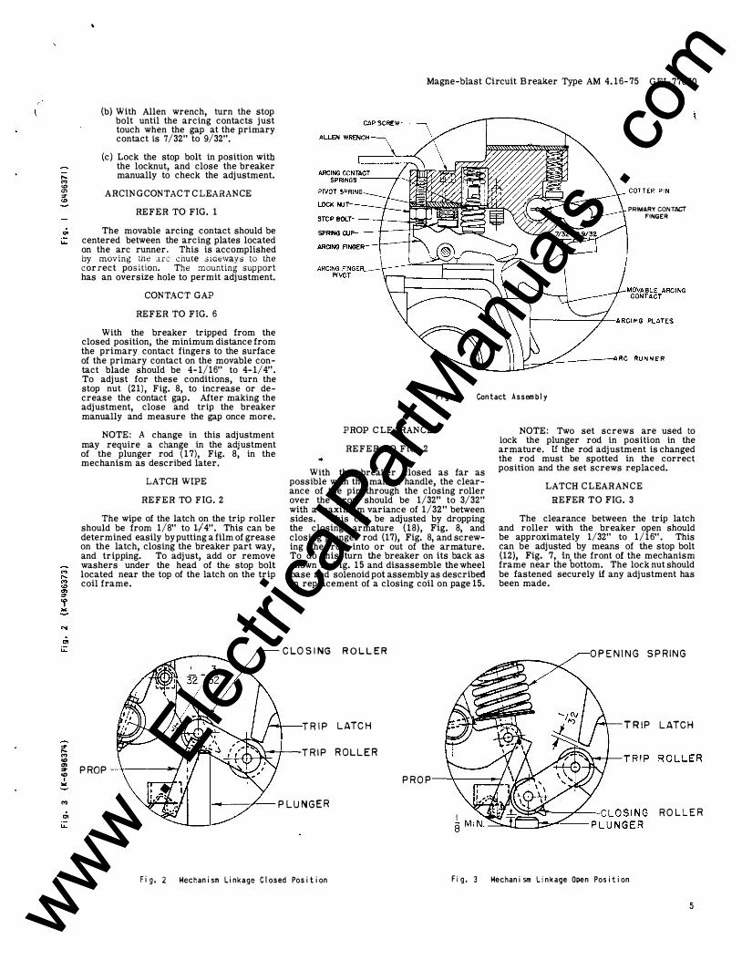
PAGE
Cross-sections - Type AM 4.16-75-1 Fig. 16 18
Front Bushing Assembly Fig. 17 19
Rear Bushing Assembly Fig. 18 20
Arc Chute Fig. 19 2 1
MS-9 Mechanism.Jor AM 4.16-75-1 Fig. 20 22
Current Trip Mechanism Fig. 21 25
Undervoltage Device, Cover Removed Fig. 22 26
PARTS RECOMMENDED FOR NORMAL MAINTENANCE
In the tabulation below are listed the parts which are usually recommended for stock for normal maintenance. Other parts are listed on the following pages.
REF. NO. CAT. NO. FOR AM-4. 16-75-1
27 0958C0649 G-0002 28 0958C0638 G-0010 34 281B793 P-1 45 236C770 G-5 52 269C864 P - 1 5 53 6301381 P-1 54 6242891 P - 1 5 6 269C828 G-2 57 6301242 G-1 58 369A460 59 6301364 P-1 60 269C828 P - 1 62 6370615 P - 1 7 6 0958C0637 P-0014
146 6306734 G-2 146 6306734 G-3 146 6306734 G-2 147 6174599 G-4 147 6174599 G-15 147 6275084 G-22 147 6174599 G-11 147 6174599 G-3 147 6174599 G-6 176 6275017 G-12 200B 6174599 G-2
PARTS FOR ALL RATINGS
NO. PER BREAKER
3 3 3 3
1 2 12
I 1 5 I 3 I 3 ! I 3 I 3 ! 3
3 3 1 1 1 1 1 1 1 1 1 1 3
DESCRIPTION
_, Movable Arcing C ontact . Movable Contact Arm � Booster Cylinder Operating Rod and Eye Bolt Primary Contact Fi�er ·
Spring for Primary ontact Spring Guide Buffer-Arcing Contact / Spring, Outside Spring, Inside Guide Pin Spring for Arc Contact Insulation Block Closing Coil (125v d-el Closing Coil (250v d-e Closing Coil (230v a-c) -Potential Trip Coil (125v d'-c) Potential Trip Coil (250v d-e) Potential Trip Coil �230v a-c) Potential Trip Coil 24v d-e) Potential Trip Coil ( 48v d-e) -Capacitor Trip Coil - ,.
Undervoltage Device Coil (230v a-c) v Current Trip Coil (3 Amp. a-c)
17 www . El
ectric
alPar
tMan
uals
. com
www . El
ectric
alPar
tMan
uals
. com

www . El
ectric
alPar
tMan
uals
. com
www . El
ectric
alPar
tMan
uals
. com

� N ..... "' "' "' ="" "' ... "' ..... u N "' "'
"'
.;. ....
GEI-77070 Magne-blast Circuit Breaker Type AM 4.16-75
5 5
2
1 2L I
REF. NO. AMPS
1 ALL 2 ALL 3 ALL 4L ALL 4R ALL 5 ALL 5A ALL 7 ALL 8 ALL 9 ALL 10 ALL 11 ALL 12L ALL M /C 12L ALL D. 12R ALL M /C 12R ALL D. 12 ALL 14 ALL 15 A L L 16 ALL
D. Mine type
18
F i g. 1 6 Cross Sect i on Type AM-� . 1 6-75- 1
PARTS REFERENCED IN FIG. 1 6
CAT. NO. FOR NO. PER AM-4. 16-75- 1 BREAKER
269C862 G2 1 2 69C846 Pl2 1 236C770 G6 1 236C771 P l O 3 236C771 P8 3 236C771 P 6 1 236C771 P7 2 2 69C830 G1 1 6597296 P5 2 6597296 P6 2 2 64B173 G4 2 2 69C861 G3 1 236C771 P 1 5 1 236C771 P17 1 236C771 P 1 6 1 236C771 P18 1 236C771 P 14 1 6176109 P21 1 414A126 P 1 2 269C828 P 1 5 1
15 I I 38 4L 4R 28 0 29 6
32
3 1 CONTACT
14
8
DESCRIPTION
Box Barrier Box Barrier Clamp Vertical Barrier Horizontal Barrier ( Left) Horizontal Barrier (Right) Horizontal Barrier (Center : Horizontal Barrier (Outer 0 Wheel Base Assembly Front Wheel & Caster Rear Wheel Secondary Coupler Plug Plunger Interlock A ssembly Box Barrier Guide (Left) Box Barrier Guide �Left) Box Barrier Guide Right) Box Barrier Guide (Right) Barrier Spacer Lifting Angle Handle
www . El
ectric
alPar
tMan
uals
. com
www . El
ectric
alPar
tMan
uals
. com

www . El
ectric
alPar
tMan
uals
. com
www . El
ectric
alPar
tMan
uals
. com
"' ....
Magne-blast Circuit Breaker Type AM 4. 16-75 GEI-77070
26
I
!=�!1 ·� .· 7 38
Fig. 1 7A Com p l e te Assembl y
3 2 I 0 : l. "��uA. �•• • �- ( �c •• ---·�� ..
. , . . '-" ..
•
- I :4 : t I � I r
37 29 43 44 42
48, 49 27
J I
3 5
i 47
F i g . 17B Component Parts
r i I I I
36
F i g . 1 7 Front Bush i n g Assembl y ( Ref. N o . 2 5 )
PARTS REFERENCED IN FIGS. 1 6, 1 7 A AND 17B
REF. NO. AMPS CAT. NO. FOR AM-4. 16-75-1
25 600 M/C 0958C0638 GOOOl 25 1200 M/C 0958C0638 G 0002 25 600 !::;. 0958C0638 G0003 26 600 M/C 0962C0728 G0001 26 1200 M/C 01 14C5488 G0001 26 600 !::;. 0898B0292 P0001 27 ALL 0958C0649 G0002 28 * ALL 0958C0638 GOOlO 29 ALL 006243035 P0001 30 ALL 006172976 P0001 31 ALL 0269C0828 P0008 32 ALL 0269C0864 GOOOB 33 ALL 0269C0864 G0002 34 ALL 028 1B0793 P0001 35 ALL 0269C0827 P0016 36 I ALL 006076401 P0025 37 ALL 006076401 P0049 38 ALL 0104A2495 P0004 39 ALL 0421A0248 P0002 40 ALL 0383A0999 P0002 41 ALL 0456A0874 P0001 42 ALL 0236C0770 P0017 43 ALL 0236C0770 POOlS 44 ALL 0236C0770 P0020 45 I ALL 0236C0770 G0005 47 ALL 0958C0649 P0002 48 I ALL 0958C0649 G0003 49 ALL 0958C0649 G0004
/::;. Mine type * Includes Reference Nos. 27 & 47
NO. PER DESCRIPTION BREAKER
3 Front Bushing Complete 3 Front Bushing Complete 3 Front Bushing Complete 3 Front Bushing 3 Front Bushing 3 Front Bushing 3 Movable Arcing Contact 3 Movable Contact Arm Assembly 6 Cup Bearing 6 Hinge Spring 3 Hinge Bolt 3 Support Assembly 3 Piston Assembly 3 Booster Cylinder 3 Pin 3 Pin 3 Pin 6 Washer 3 Piston Ring 3 Piston Ring Expander 3 Piston Ring Equalizer 3 Rod 3 Nut 3 Eye Bolt 3 Operating Rod and Eye Bolt 3 Contact 3 Blade Assembly (Right) 3 Blade Assembly (Left)
.� � .. - ' 'T/ , .
• •
I I I I I
33 39
! I !
!
19 www . El
ectric
alPar
tMan
uals
. com
www . El
ectric
alPar
tMan
uals
. com

www . El
ectric
alPar
tMan
uals
. com
www . El
ectric
alPar
tMan
uals
. com

•
GEl-77070 Magne-blast Circuit Breaker Type AM 4 . 1 6 - 75
I I i !
:
! i I I I I ! I i ·
2 0
5 9 5 8 6 0 5 6
L __ , i
I I
.-J r.:::•
' 'lP
..,.. 4>
-1-55 6 4 63 6 1 57
54 5 3
52
51
.:..
""!
F i g . 1 8A Comp l ete Assemb ly F i g . 1 8 8 Component Parts
R E F . NO.
50 50 50 51 51 5 1 52 53 54 55 56 57 58 5 9 60 61 62 63 64
:
'
'
6 Mine Type
A MPS
600 1200
600 6 600
1 2 00 600 6
ALL ALL ALL ALL ALL ALL ALL ALL ALL ALL ALL ALL ALL
F i g. 18 Rear Assembl y ( Ref. No. 50)
PARTS REFEREN C ED IN FIG. 1 8
CAT. N O. FOR AM-4. 1 6 - 7 5 - 1
0 9 5 8C0638 G00 1 2 0958C0638 G00 1 3 0 9 5 8C 0638 G00 14 0962C0728 G0002 0 1 14C5488 G0002 0898B0292 P0002 0269C 0864 P00 1 5 0 0 6 3 0 1 3 8 1 PODO l 006242891 PODO l 0269C0828 P000 7 0269C0828 G0002 00630 1242 GOOOl 03 69A0460 006301364 PODOl 0 2 69C0828 PODO l 0 2 69C0828 GOOO l 006370615 PODO l 0 2 69C0828 P00 1 4 0269C0828 P0006
NO. PER BREAKER
3 3 3 3 3 3
1 2 12 1 5
6 3 3 3 3 3 3 3 3 3
DESCRIPTION
Rear Bushing Asse mblv Clmplete Rear Bushing Assembl�· CJrr.plete Rear Bushing Assemb ly C.Jmplete Rear Bushing Rear Bushing Rear Bushing Primary Contact Spring for Primar�- ( :>ntact Sp ring Guide Washer Buffer Arcing C ontact Spring, Outside Spring, Inside Guide Pin Contact Support Spring for Arcing :::ontact Spring Guide for Arcin'( Contact Cotter Pin
0) � ,... "' N 0 � "' 00 ... ... 00
.,; "' u..
www . El
ectric
alPar
tMan
uals
. com
www . El
ectric
alPar
tMan
uals
. com

www . El
ectric
alPar
tMan
uals
. com
www . El
ectric
alPar
tMan
uals
. com

.;, ...
-lO: "" "" N 0 e "' � .;, ...
..... "' ...
., ,, r _..-.... ... ---� -- --- � �·- - - - - . ..c. - -
F i g. 1 9A Ca�plete Assemb l y
REF. NO.
75 76 77 78 79 80 81 82 83 83 85 86 87 88 89
Magne-blast Circuit Breaker Type AM 4. 16-75 GEI-77070
80� �79 87-------6 . !
77�Kc �==� - . . 76 82 J " . • . 89 - . ��78 86 -:. . .. -�81 83 •
•
-��;:= 77 · - 88 89 83 82
81
F i g . 1 9 8 Componen t Parts F i g . 1 9C Cut-away V i ew
F i g , 1 9 Arc Chute ( Ref. No. 75)
PARTS REFERENCED IN FIG. 19
CAT. NO. FOR NO. PER DESCRIPTION AM-4.16-75-1 BREAKER
0634D0366 G0001 3 Arc Chute Assembly Complete 0958C0637 P0014 3 Insulation Block 0269C0854 G0001 3 coil 0958C0637 G0001 3 Coil Support 0958C0637 G0004 3 Pole Piece 0958C0637 G0005 3 Pole Piece 0958C0637 G0002 3 Arc Runner 0958C0637 G0003 3 Arc Runner
* 0958C0636 P0001 3 Arc Chute Side * 0958C0636 P0002 3 Arc Chute Side
0958C0637 P0012 3 Spacer 0958C0637 P0013 3 Spacer 0958C0637 P0009 6 Shield 0958C0637 P0010 3 Core 0958C0637 POOll 3 Insulating Tube
* Shtpped m Paus Only.
21 www . El
ectric
alPar
tMan
uals
. com
www . El
ectric
alPar
tMan
uals
. com

www . El
ectric
alPar
tMan
uals
. com
www . El
ectric
alPar
tMan
uals
. com

GEI-77070 Magne-blast Circuit Breaker Type AM 4.16-75
22
1 80 --------184 ---------;
183 ------. 1 85 --�
18 1 _ _____,
187 186 --l o2 147 100 10 1 10 2 --::::-::::::::::rl-1 76 \�,.....::::::_......::�
103 -----�u 104 ---�---AI7r 156 ------l¥9
15 7 -------f" 128 ------
r-----164 163
------- 177 -.-----a 29
�W-:...�:::ur---- 158 ��H-----.30
-��" 13 1 !05
----- 1 1 5 --132
�--1 1 6 �--- 134
120 1 1 7
....___ 1 1 8 "-.--t:E='"J-�P>-... 179 ------ 178 '---- 145
.,___- 1 3 3 '--- 1 1 9 108 ----
175 ----109·-------1 1 0 --___,...
1 1 1 ----
�� �- �_.::_-:��:!ff�-- 1 22 "7'!1"'74==F="''r-- --jj-T-----,.---=�� �-----1 2 1
107 ------' 106 -------' 127 ------� 1 1 2 ----------l 146 ---------+1� 135--------41t--+--+-----1
......_ __ 1 23
1 1 3 ----------HI-;---+.. Lr====�i:.F=�
1 14 -------411--1----41-
1� ----------���===9==�
:k-188 I !
124
1 26
... m-----161 i i 1 5 9 ; , ! � -- 1 90
1 9 1 dd=:r---- 160
� 167 ---------i:!t:l' 165 ---------�
1 1 0 . ',
154�,
F i g . 20A Cross Sect i on
F i g. 20 MS-9 Mechan i sm for AM � . 1 6-75- 1 ( Con ' t . )
0 \ . . ._____u L -- j
"' u..
www . El
ectric
alPar
tMan
uals
. com
www . El
ectric
alPar
tMan
uals
. com

www . El
ectric
alPar
tMan
uals
. com
www . El
ectric
alPar
tMan
uals
. com

•
g ""
1 5 2
REF. NO. MVA
100 ALL 101 ALL 102 ALL 103 ALL 104 ALL 105 ALL 106 ALL 107 ALL 108 ALL 109 A LL 110 ALL 111 ALL 1 1 2 A L L 113 ALL 114 ALL 115 ALL 116 ALL 1 1 7 A L L 118 ALL 119 ALL 120 ALL
1 5 1
Magne-blast Circuit Breuer Typ e AM 4.16-75 GEl-77070
141 143
169
ft-....:0.,�::::-'-'�-138 r--+t:��=ttlri4S
�IL--;I.-It---170
F i g . 20B Pos i t i ve I n terl ock L i nk age
150 149
Fi g . 20C Tri p Mechan i sm ( Ref. Mo. 1 53 )
F i g. 20 MS-9 Mech an i sm for AM � . 1 6-75- 1
'----++l-1139
148
PARTS REFERENCED IN FIGS. 20A, 20B AND 20C
CAT. NO. FOR NO. PER DESCRIPTION AM-4. 16-75-1 MECHANISM
269C858 G-4 1 Latch 6077971 P-7 1 Pin 414A112 P-34 1 Needle Bearing 6076404 P-59 2 Pin 6509718 1 Spring 456A387 P-1 1 Spring 6370095 P-2 1 Pin 269C857 G-6 1 Link Assembly 6370095 P-3 1 Pin 6370095 P-4 1 Pin 269C858 G- 1 1 Link 6370646 1 Spring 269C859 P-7 1 Pot 6440893 P - 1 1 Shim 269C859 P-9 1 Armature 269C861 P-10 1 Spring 456AB66 P-1 1 Cut-off Switch 6076404 P-105 3 Pin 269C858 P-14 1 Pin 269CB5B P-13 2 Link 6370289 P-1 2 Crank
23 www . El
ectric
alPar
tMan
uals
. com
www . El
ectric
alPar
tMan
uals
. com

• www .
Elec
tricalP
artM
anua
ls . c
om
www . El
ectric
alPar
tMan
uals
. com

GEI-77070 Magne-blast C ircuit Breaker Type AM 4. 16-75
PARTS REFERENCED IN FIGS. 20A, 20B AND 20C (Con't.)
REF. NO. MVA
121 ALL 122 ALL 123 ALL 124 ALL 125 ALL 126 ALL J. �
- -
I .... .... i f28 ALL
A 129 ALL 130 ALL 131 ALL 132 ALL 133 ALL 134 ALL 135 ALL 138 75 139 75 140 75 141 75 142 75 143 75 145 ALL 146 ALL 146 ALL 146 ALL 147 ALL 147 ALL 147 ALL 147 ALL 147 ALL 147 ALL 148 75A 149 75A 1 50 75A 151 75A 1 52 75A 153 75A 154 ALL 1 56 ALL 1 57 ALL 1 59 ALL 160 ALL 161 ALL 162 ALL 163 ALL 164 ALL 165 ALL 166 ALL 167 ALL 169 75 170 75 171 75 172 75 174 75 175 ALL 176 ALL 177 ALL 178 ALL 179 ALL 180 ALL 181 ALL 182 ALL 183 ALL 184 ALL 185 ALL 186 ALL 187 ALL 188 I ALL 189 ALL
24
CAT. NO. FOR AM-4. 16-75- 1
269C858 G-3 6076404 P-159 6301361 269C860 P-4 6370647 6192382 P-6 ,., ! .,.. ,... ,-. I (' ,-., 0 0 " "j: j ' ":! 6441826
'-' -
269C86 1 P-11 414A109 P-6 269C861 P-7 6245880 6210959 P-2 6370095 P-1 269C859 P-10 958C645 P-5 958C645 G-2 958C645 P-4 958C645 P-9 258C695 P-5 456A866 P - 1 258C694 P-7 6306734 G-2 6306734 G-3 6306734 G-2 6174599 G-4 6 1 74599 G- 1 5 6275084 G-22 6 174599 G-11 6 1 74599 G-3 6 174599 G-6 6438456 G-3 6242840 P - 1 6242839 P - 1 6242838 P - 1 6242837 ·P - 1 6438456 G-4 269C859 G-3 684C642 G-1 6002721 P - 1 1 4 281B792 P-2 281B792 P-3 281B792 P-4 269C861 G-1 414A146 P-4 269C861 G-4 269C859 G-2 269C859 P-6 269C859 P-8 958C645 P-3 958C645 P-21 958C645 P-19 958C645 P-20 456A343 P-1 6 176109 P-71 6242834 P-1 6247762 P-1 269C857 P-32 6370567 P-51 269C860 P-2 269C860 G-2 269C860 P-6 269C860 P-9 269C860 P-10 269C860 P - 1 1 6420279 P - 1 6076401 P - 1 2 5 414A146 P - 1 269C860 P-20
NO. PER MECHANISM
1 1 1 1 1 1 . 1 1 2 1 1 1 1 1 1 1 1 1 1 1 1 1 1 1 1 1 1 1 1 1 1 1 1 1 1 1 1 1 2 1 1 1 1 1 1 1 1 4 1 2 2 1 1 2 2 2 4 2 1 1 1 1 1 1 1 1 1 1
DESCRIPTION
Prop Pin Spring Support Spring Operation Counter - 1 .. -Ball Bearing Disc Cushion Guide Seat Crank Pin Plunger Prop Stop Blade and Pin Paddle Crank Shaft Inter lock Switch Shaft Closing Coil (125v d-e) Closing Coil �250v d-e) Closing Coil 230v a-c) Potential Trip Coil �125v d-e) Potential Trip Coil 2 50v d-e) Potential Trip Coil (230v a-c) Potential Trip Coil ( 24v d-e) Potential Trip Coil ( 48v d-e) Capacitor Trip Coil Trip Arm Bracket Asm. Crank Arm Crank Shaft Trip Latch Trip Mechanism, Complete Latch Checking Switch and Support Terminal Block (6 Point) Spacer for Terminal Block Plunger Rod Bracket Manual Trip Assembly Flex Nut Support Bracket Assembly Plate Stud Support Pin Pin Pin Spring Spacer Spacer Pin Pin Bushing Base P late Indicator Crank and Pin Clevis Rod Pin Support Pin Flex Nut Connection Link
i
www . El
ectric
alPar
tMan
uals
. com
www . El
ectric
alPar
tMan
uals
. com

www . El
ectric
alPar
tMan
uals
. com
www . El
ectric
alPar
tMan
uals
. com

"' "' "' "' "' 0 00
:8 "' "' "' 0 00
�
• ..
2 0 0
2 1 3 2 1 4
•
l . .
---j-2 1 2
Magne-blast Circuit Breaker Type AM 4.16-75 GEI-77070
-j-2 10 2 17 2 1 2
F i g . 2 \ A Fron t V i ew
__ 2 12
2 0 5 l2 1 0 2 1 2 2 0 8 1 2 1 8 1
207 209
F i g . 2 \ B Rear V i ew
F i g . 2 1 Current Tr i p Mechan i sm ( Ref. No. 200)
PARTS REFERENCED IN FIGS. 2 1A AND 2 1B
REF. NO. CAT. NO. FOR NO. PER DESCRIPTION AM-4.16-75-1 BREAKER
200A 6193957 G-13 1 Current Trip Mechanisjll 200B 6174599 G-2 3 Coil (3 Amp. a:..cr 200C 6193957 G-7 1 Sol. Frames and Armature Assemblies 201 4905058 G-4 3 Solenoid Frame 202 6193957 P - 8 2 Bearing 203 6247930 P - 1 1 Spring Guide 204 6370224 P - 1 1 Shaft 205 6509725 P - 1 1 Spring 206 6247928 P - 1 1 Pin 207 6247932 P - 1 2 Spacer 208 6442898 P - 1 1 Cam Latch 209 6508774 P - 1 10 1 Latch Bracket Assembly 210 6327893 P-2 1 Frame 2 1 1 624792.9 P-2 1 Pin 212 6247924 P - 1 3 Calibrating Tube 213 6247925 P - 1 3 Guide Pin 214 6477094 P - 1 3 Spring 215 6247927 P-1 3 Pin 2 1 6 6247926 P-1 3 A rmature 2 1 7 2236575 P - 1 6 Guide 218 269C858 G-4 1 Latch 219 6077971 P-7 1 Shaft 220 6509718 P-1 1 Spring 221 6442397 P - 1 1 Guide 222* 6509714 P - 1 1 Spring 223* 6508767 P - 125 1 Adjusting Rod Assembly 224* 6442895 P - 1 1 Clevis 225* 6247919 P - 1 3 Calibrating Strip 226* 6370500 P-9 1 Cover 227 6193957 P -209 5 Pin 228 6193957 P-34 3 Pin
• Not Shown
25 www . El
ectric
alPar
tMan
uals
. com
www . El
ectric
alPar
tMan
uals
. com

• ..
•
www . El
ectric
alPar
tMan
uals
. com
www . El
ectric
alPar
tMan
uals
. com

.•
GEI-77070 Magne-blast Circuit Breaker Type AM 4.16-75
2 6
R E F . NO.
250
250
251 252 253 254 255 256 257 258 259 260 261 262 262 263 264 265 266 267 268 269 270 271 272 273• 274*
263 ------'
------ 2 5 8
� s a -�--- --
2 6 l c...,' ----
2 6 2 -----
260 ------;:;!!--_ 26 7------"!l-/ .. 266 --�-�"-2 7 1 ---L--.L-,c--::!!!!!!!�
2 6 7 -----:'
2 5 2-=---
2 6 5
2 6 2
2 5 9 2 5 5 2 56
2 5 3
2 5 4 2 5 7
270 2 5 1
2 6 9
F i g. 2 2 Undervo l tage Dev i ce, Cover Removed (Ref. No. 2 50 }
PARTS REFERENCED IN FIG. 22 FOR PG-6 AND PG-7 UNDERVOLTAGE DEVICES
UNDERVOLTAGE CAT. NO. FOR NO. PER DESCRIPTION DEVICE TYPE AM-4. 16-75-1 MECHANISM
PG-6 6476723 G-14 1 Undervoltage Device, Complete INSTANTANEOUS
PG-7 6476723 G-38 1 Undervoltage Device, Complete TIME DELAY
ALL 6275017 G-12 1 Undervolta�e _Device_, Coil (230v a-c) ALL 6275259 G-1 1 Cut-out Swttch ALL 6275264 P-1 1 Operating Lever ALL 2412699 P-1 2 Spring ALL 2437146 P - 1 2 Roller ALL 2239800 P - 1 1 Pin ALL 2433013 P - 1 2 Guide Strip ALL 6172878 P - 1 1 Spring ALL 6300040 G-3 1 Crank and Shaft ALL 6243282 P - 1 1 Eye Bolt ALL 6440967 P - 1 1 Coupling PG-6 6076401 P - 101 2 Pin PG-7 6076401 P - 10 1 1 Pin ALL 6440971 P - 1 1 Trip Nut ALL 6440966 P - 1 1 Trip Rod ALL 6243283 P - 1 1 Link PG-7 6243281 P - 1 2 Link PG-7 6076401 P - 106 2 Pin PG-7 6926026 G-2 1 Escapement Device ALL 2234099 G-1 1 Solenoid Frame ALL 2236258 P - 1 2 Spring ALL 2234101 G-1 1 Core ALL 6301233 G-1 1 Adjusting Plate ALL 6113966 G-4 1 Cover ALL 6043479 P-1 1 Thumb Nut for Cover
• Not Shown
-;n :r "' 8 0 "" � N N
.;, ...
www . El
ectric
alPar
tMan
uals
. com
www . El
ectric
alPar
tMan
uals
. com

.. •.
www . El
ectric
alPar
tMan
uals
. com
www . El
ectric
alPar
tMan
uals
. com


![Molecular dynamics simulations of matrix-assisted laser ......2 L.V. Zhigilei et al./International Journal of Mass Spectrometry 12305 (2002) 1–22 [3–7]. The complexity and diversity](https://static.fdocuments.in/doc/165x107/60e5ce7a6254f242da5e972b/molecular-dynamics-simulations-of-matrix-assisted-laser-2-lv-zhigilei.jpg)