Lubricating oils for enclosed gear drives - skama.gr · Lubricating oils for enclosed gear drives...
20
Lubricating oils for enclosed gear drives Klüber solutions for gears of any size Lubrication is our World
Transcript of Lubricating oils for enclosed gear drives - skama.gr · Lubricating oils for enclosed gear drives...

Lubricating oils forenclosed gear drives
Klüber solutions for gears of any size
Lubrication is our World
2
Contents Page
Introduction
Selecting gear oils for newly installed gears
Application factor KA
Lubricating oils for gears in general machine building
Required viscosity of the lubricating oil
Determining the Klüber viscosity index, KVZ
Determining the viscosity grade
Viscosity selection diagramm
Selecting gear oils
Changeover from mineral oil to synthetic oil lubrication
How to proceed with oil changes
3
4
6
8
9
10
11
12
14
17

3
Today, the manufacture of gears of allperformance grades is characterizedby demands for the transmission ofever growing power and torque while,at the same time, reducing size andweight.
This calls for new gear designs, newmaterials, improved surface treatment,modern production techniques as well as the application of mineral andsynthetic high-performance lubricants.
To the same extent that the perform-ance weight of the toothed gears is decreased, the service claims on the gear lubricants have increased.This particularly applies to their wear-reducing and anti-fretting effects aswell as to their stability towards highgear temperatures.
The heat generated during operationmust be removed via ever decreasinghousing surfaces areas. This results in increasing operating temperatureswhich obviously affect the useful life of both the gear box and the lubricants.
Measures for reducing frictional losseson the various gear components helpreduce the temperature of the gear.Experience has shown that the use ofhigh-performance mineral and syn-thetic gear oils helps reduce powerlosses and operational temperatures.
Increasing requirements for gear oils
Thus, in many cases, the installation or fitting of expensive cooling devicesis no longer necessary.
For these reasons synthetic lubricatingoils have gained importance in thisfield. Apart from reduced gear tem-peratures, considerably longer oil lifecan be achieved, depending on therequirements. For worm gears, thismay mean lifetime lubrication.
For the technical designer, a higherpermissible operating oil temperaturemeans higher power can be trans-mitted on the same designed space.
The results can be measured in con-siderable energy and cost savings.
Furthermore, substantially longer oillife means substantially less lubricantconsumption and smaller amounts ofused oil. This means environmentalprotection and a reduction of disposalcosts.
This guide is intended to help you find the most suitable gear lubricant,quickly and safely.

4
Area of application: General machine building
Type of gear– spur gears and straight bevel gears – worm gears– helical bevel gears – hypoid
gear sets
Operating oil temperature (°C)Oil sump temperature and/or tempera-ture of the injected oil.
Load demands on gearClassification as low – medium – highFor the determination of the loaddemands on gears, the applicationfactor KA can be used, which is calcu-lated using tables 3 ... 6. The tableshave been taken from DIN 3990 part 1,appendix A (12.87).
The selection of the suitable lubricationoil type is then made using table 2.
ExampleDetermination of the suitable oil typefor the worm gear stage of a gearmotor driving a loaded belt conveyor.
Selecting gear oils for newly installed gears 1. Determining the suitable lubricant type depending
on the type of gear, operating oil temperature and load demands
Operating conditionsDriving torqueSpeed of the worm Centre distance Drive Expected oil temperature
Determination of the loaddemandsAfter determination of the application factor KA the load demand is taken fromtable 1. For KA refer to tables 3, 4 and 5.
Operational mode of the drive/electricmotor: uniform.
Operational mode of the driven machine/loaded belt conveyor: moderate shocks.
According to table 3 it follows: KA = 1.25 According to table 1 the load demand onthe gear is medium.
Suitable oil typeThe selection of the type of lubricating oil is made according to table 2. For theworm gear mentioned in the example,centre distance a = 63 mm, with an operating oil temperature of approx 85 °C and a medium load oil type C = Klübersynth GH 6 is the suitablegear oil.
T2 = 300 Nmns = 350min–1
a = 63 mmElectric motor approx. 85 °C

Application factor KA
Load demands on gears
> 1 to 1.5
medium
>1.5
high
1
low
Table 1: Load demands on gears depending on the application factor KA
Table 2: Selection of the suitable gear oil depending on the operating temperature, type of gear and load demands
A Klüberoil GEM 1- … N Series*
B Klübersynth GEM 4- … N Series*
C Klübersynth GH 6 Series*
D Klübersynth GEM 2 Series
E Klüberoil 4 UH1- … N Series*
F Klübersynth UH1 6 Series*
Legend
Operating oil tem-perature [°C]
< – 25
– 25 to 80
0 to 120
> 120 to 160
Type of gear
Spur/bevel gear
Worm gear
Spur/bevel gear
Worm gear
Spur/bevel gear
Worm gear
Spur/bevel gear
Worm gear
Area of application
Gear load
–
–
D
D
D
D
–
–
B
B
B
C
C
C
C
C
B
B
A
C
B
C
C
C
B
B
A
B
B
B
C
C
–
–
F
F
F
F
F
F
E
E
E
E
E
E
F
F
Industrial gears Environment Food industry
highlow - high mediumhigh medium low
5
* Products of the Lube & Sealprogram. For further informationplease refer to www.klueber.com

6
Table 4: Examples of drives with different modes of operation
DriveMode of operation
* Verified by vibrational tests and/or by experience with similar systems.** Compare to service life curves ZNT; YNT of the material in DIN 3990 part 2 and part 3. Consideration of temporarily acting peak-
load torques
uniform
minor shocks
moderate shocks
heavy shocks
electric motor (e.g. d.c. motor), steam/gas turbine in uniform operation* (low, rarely occurring startingtorques)**
steam turbine, gas turbine, hydraulic, electric motor (higher, more frequently occurring starting torques)**
multi-cylinder combustion engine
single-cylinder combustion engine
Table 3: Application factor KA
Mode of operation of the driven machineMode of operation ofthe drive
moderate shocks medium shocks heavy shocksuniform
The values stated apply to the nominal torque of the driven machine, alternatively to the nominal torque of the driving motor, as far as this corresponds to the torque demand of the driven machine. The values stated only apply to machines which are not working inthe resonance area and only in case of uniform power requirements. For applications with unusual loads, motors with high startingtorques, intermittent operation, when operated under extreme, repeated shock loads, the gears should be checked for safety regard-ing static strength and endurance limit. For examples please refer to DIN 3990 part 6, page 9.
uniform
minor shocks
moderate shocks
heavy shocks
1.00
1.10
1.25
1.50
1.25
1.35
1.50
1.75
1.50
1.60
1.75
2.0
1.75
1.85
2.0
2.25 or higher
Application factor KA
DIN 3990 part 1, appendix A

Driven machineMode of operation
1 Nominal torque = maximum cutting, pressing, punching torque 2 Nominal torque = maximum starting torque 3 Nominal torque = maximum rolling torque 4 Torque from current limitation 5 KA up to 2.0 due to frequent band ruptures
uniform
medium shocks
heavy shocks
moderate shocks
Power generators; uniformly loaded belt conveyors or apron conveyors; worm conveyors; light elevators;packing machines; feed drives of machine tools; fans; light centrifuges; centrifugal pumps; agitators andmixers for light liquids or materials with uniform density; cutters, presses; punches1; slewing gears;traversing mechanisms2.
Irregularly (e.g. with piece goods) loaded belt conveyors or apron conveyors; main drives of machinetools; heavy elevators; slewing gears of cranes; industrial and mine fans; heavy centrifuges; centrifugalpumps; agitators and mixers for viscous liquids or materials with irregular densities, piston pumps withseveral cylinders; metering pumps; extruders (in general); calenders; rotary kilns; rolling mills3 (continuouszinc band, aluminium band as well as wire and bar rolling mills).
Extruders for rubber; mixers with intermittent operation for rubber and plastic materials, light-weight ballmills; wood processing (gate saws, turning lathes); break-down mills3,4; hoisting gears; single-cylinderpiston pumps.
Excavators (bucket wheel drives), chain and bucket drives, screen drives, shovel dredgers; heavy ballmills; rubber kneaders; crushers (stone, ore); iron and steelworks machines; heavy metering pumps;rotary drilling gears; brick moulding machines; bark peeling drums; peeling machines; cold strip mills3,5;briquetting presses; pan grinders.
Table 5: Industrial gears; examples of the mode of operation of the driven machine
7
Driven machineMode of operation
uniform
moderate shocks
heavy shocks
medium shocks
Radial compressors for air conditioners – for process gas; performance test bench; generator and exciterfor base load or continuous load, paper mill main drive.
Radial compressors for air and pipelines; axial compressors; centrifugal fans; generator and exciter forpeak load; centrifugal pump (all types, except for those explicitly stated as follows); axially-flown rotarypump, all types; gear pump; paper industry; Jordan or refiner machine; paper machine auxiliary drive; pulp stock stamper.
Rotary lobe fans; radially-flown rotary lobe compressor; piston compressor (3 or more pistons); suction fans in industry and mining (large ones, with frequent starting procedures); boiler feed centrifugal pump, rotary lobe pump, piston pump (3 or more pistons).
Reciprocating piston compressor (2 pistons); centrifugal pump (with surge tank); sludge pump; pistonpump (2 pistons).
Table 6: Industrial gears; examples of the mode of operation of the driven machine
8
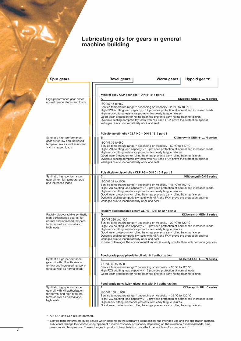
Hypoid gears* Worm gearsBevel gearsSpur gears
Mineral oils / CLP gear oils – DIN 51 517 part 3A Klüberoil GEM 1- … N series
ISO VG 46 to 680 Service temperature range** depending on viscosity – 20 °C to 100 °C High FZG scuffing load capacity > 12 provides protection at normal and increased loads. High micro-pitting resistance protects from early fatigue failures Good wear protection for rolling bearings prevents early rolling bearing failures Dynamic sealing compatibility tests with NBR and FKM prove the protection against leakages due to incompatibility of oil and seal
Polyalphaolefin oils / CLP HC – DIN 51 517 part 3B Klübersynth GEM 4- … N series
ISO VG 32 to 680 Service temperature range** depending on viscosity – 50 °C to 140 °C High FZG scuffing load capacity > 13 provides protection at normal and increased loads. High micro-pitting resistance protects from early fatigue failuresGood wear protection for rolling bearings prevents early rolling bearing failures Dynamic sealing compatibility tests with NBR and FKM prove the protection against leakages due to incompatibility of oil and seal
Polyalkylene glycol oils / CLP PG – DIN 51 517 part 3 C Klübersynth GH 6 series
ISO VG 32 to 1500 Service temperature range** depending on viscosity – 45 °C to 160 °C High FZG scuffing load capacity > 13 provides protection at normal and increased loads. High micro-pitting resistance protects from early fatigue failures Good wear protection for rolling bearings prevents early rolling bearing failures Dynamic sealing compatibility tests with NBR and FKM prove the protection against leakages due to incompatibility of oil and seal
Rapidly biodegradable ester/ CLP E – DIN 51 517 part 3 D Klübersynth GEM 2 series
ISO VG 220 and 320 Service temperature range** depending on viscosity – 20 °C to 120 °C High FZG scuffing load capacity > 13 provides protection at normal and increased loads. High micro-pitting resistance protects from early fatigue failures Good wear protection for rolling bearings prevents early rolling bearing failures Dynamic sealing compatibility tests with NBR and FKM prove the protection against leakages due to incompatibility of oil and seal In case of leakages the environmental impact is clearly smaller than with common gear oils
Food grade polyalphaolefin oil with H1 authorization E Klüberoil 4 UH1- … N series
ISO VG 32 to 1500 Service temperature range** depending on viscosity – 35 °C to 120 °C High FZG scuffing load capacity > 12 provides protection at normal loads Good wear protection for rolling bearings prevents early rolling bearing failures
Food grade polyalkylen glycol oils with H1 authorization F Klübersynth UH1 6 series
ISO VG 100 to 680 Service temperature range** depending on viscosity – 35 °C to 120 °CHigh FZG scuffing load capacity > 13 provides protection at normal and increased loads High micro-pitting resistance protects from early fatigue failuresGood wear protection for rolling bearings prevents early rolling bearing failures
Synthetic high-performancegear oil with H1 authorizationfor low and increased tempera-tures as well as normal loads
Rapidly biodegradable synthetichigh-performance gear oil fornormal and increased tempera-tures as well as normal andhigh loads
Synthetic high-performancegear oil for high temperaturesand increased loads
Synthetic high-performancegear oil for low and increasedtemperatures as well as normaland increased loads
High-performance gear oil fornormal temperatures and loads
Lubricating oils for gears in generalmachine building
* API GL4 and GL5 oils on demand.
** Service temperatures are guide values which depend on the lubricant's composition, the intended use and the application method. Lubricants change their consistency, apparent dynamic viscosity or viscosity depending on the mechano-dynamical loads, time,pressure and temperature. These changes in product characteristics may affect the function of a component.
Synthetic high-performancegear oil with H1 authorizationfor normal and high tempera-tures as well as normal andhigh loads

9
Mineral oilsIf you have determined that you require a Type A lubricant (KlüberoilGEM 1- … N), your next step must be to determine the required nominalviscosity at 40 °C according to DIN 51 509 part 1.
Synthetic oils All the other gear oils determined from table 2 are synthetic gear oils, forwhich the viscosity selection procedureaccording to DIN 51 509 part 1 is notapplicable. This standard applies onlyto mineral oils with a viscosity index(VI) of approx. 90 to 95 as it is basedon their specific viscosity-temperaturerelation. Therefore, when using syn-thetic gear oils and selecting the vis-cosity without calculations, e.g. on theEHD theory etc., the different viscosity-temperature relation of synthetic oilsversus mineral oils needs to be takeninto account.
Required viscosity of the lubricating oil2. Determining the required lubricating oil viscosity
Since there are no standardized proce-dures for determining the viscositywhen using synthetic oils, and sincethe common procedures are quiteexpensive, Klüber has developed dia-grams for our synthetic gear oils withthe help of which you can select therequired ISO VG class in a simple andsafe way.
The selection is made partly accordingto DIN 51 509. Here, the force-speedfactor ks/v according to DIN 51 509part 1 needs to be calculated for thegear type to be considered. Dependingon the result of that, the so-calledKlüber viscosity index KVZ is thendetermined.
Using the KVZ and the operating oiltemperature to be expected, the usercan then directly select the requiredISO VG class from the correspondingviscosity selection diagram of theselected Klüber product series.
During the preparation of the selec-tion diagrams, the different viscosity-temperature behaviour of synthetic oils has already been taken into consideration.
ExampleExample continued from page 4– Lubricating oil type selected:
Klübersynth GH 6, polyglycol oil– Operating oil temperature to be
expected: approx. 85 °C– Force-speed factor ks/v:
3428.6 N x min x m2
1 gear ring
2 left flank
3 right flank
4 reference cylinder (pitch cylinder)
5 right flank line
a gear centre
b face width
d pitch circle
df root circle
da tip circle
e space width
ha addendum
hf dedendum
p pitch
s tooth thickness in pitch circle
Designation of the spur teeth(left or right flank)
Legend

10
The selection of the viscosity gradeaccording to our example alwaysapplies to one gear stage only. Formulti-stage gearings, the viscosityselection needs to be made separate-ly for each gear stage. It is importantto select from the viscosity gradesdetermined that grade which presentsthe most suitable compromise for asafe lubrication both of the gear andthe other gear components to belubricated e.g. bearings.
To ensure adequate lubricant supply incold start or low ambient temperaturesituations, you may have to select alower viscosity grade. Check the spe-cific viscosities at the appropriate starttemperature or test the components atthe start temperatures expected.
≤ 60
> 60 to 400
> 400 to 1800
> 1800 to 6000
> 6000
5
6
7
8
9
Force-speed factor ks/v [ N x min x m–2 ]
Klüber viscosityindex KVZ
Table 8: KVZ depending on the ks/vfactor for worm gears
Determining the Klüber viscosity index, KVZDetermination of the KVZ accordingto table 8 (worm gears). In the presentcase, the force-speed factor ks/v wascalculated using 3428.6 N x min x m2.According to table 8, this results in aKVZ of 8.
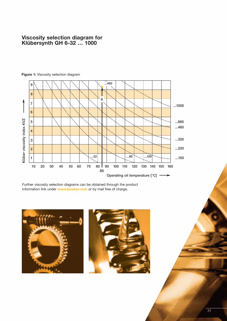
Determining the viscosity gradeThe selection of the required viscositygrade is performed using the viscosityselection diagram for Klübersynth GH 6, figure 1. With the determined Klüber viscosityindex KVZ 8 and the expectedoperating oil temperature of approx. 85 °C, the diagram suggestsISO VG 460 as the required viscositygrade, i.e. the required lubricant is Klübersynth GH 6-460.
Notes regarding the Klüber viscosity selection procedureIn the above example for determiningthe viscosity, the coordinate inter-section of the KVZ 8 area and theoperating oil temperature (85 °C) islocated between the ISO VG curves320 and 460, which means that theviscosity grade to be selected is notclearly defined. In such a case, thehigher viscosity grade should alwaysbe selected, which is ISO VG 460 in this case.
≤ 0.02
> 0.02 to 0.08
> 0.08 to 0.3
> 0.3 to 0.8
> 0.8 to 1.8
> 1.8 to 3.5
> 3.5 to 7.0
> 7.0
1
2
3
4
5
6
7
8
Force-speed factor ks/v [MPa x s x m–1]
Table 7: KVZ depending on the ks/vfactor for spur gears and straightbevel gears
Klüber viscosityindex
11
Figure 1: Viscosity selection diagram
Further viscosity selection diagrams can be obtained through the productinformation link under www.klueber.com or by mail free of charge.
Viscosity selection diagram forKlübersynth GH 6-32 … 1000
...220
...150
...320
...460
...680
...1000
6
7
8
9
2
1
3
4
5
Klü
ber
vis
cosi
ty in
dex
KV
Z
Operating oil temperature [°C]
10 20 30 40 50 60 70 8085
90 100 110 120 130 140 150 160
8
...460
...32 ...80 ...100

MaintenanceWhen refilling or exchanging oil, it isimportant that the oil chosen meets the specifications of the gear or plantmanufacturer with regard to oil type,quality and viscosity requirements.
Lubricating oils from different manu-facturers not only differ in their baseoils, but also in their additives and thus have differing characteristics. So,mixing of such lubricants might resultin quality losses not only of the wearprotection characteristics, but also ofthe viscosity-temperature relation.
For this reason, the same oil typeshould always be used for refilling. If this is not possible, the instructionsin the following paragraphs shouldabsolutely be observed.
Miscibility of different gear oil types
Gear oils on mineral oil basis– e.g. Klüberoil GEM 1- ... N series –can be mixed with each other. The prescribed standard requirements, e.g. CLP etc. as well as the viscositydemands shall be met in any case.Mineral oils are miscible with syntheticlubricating oils based on polyalpha-olefin (PAO) and ester. They are notmiscible with polyglycol (PG).
Selecting gear oilsHow to select gear oils for gears already installed
Gear oils based on polyalphaolefin – PAO e.g. Klübersynth GEM 4- ... N seriesmay be mixed without hesitation withresidues of mineral oil which cannot beremoved by normal oil draining, up toapprox. 5%, including oil tank and filter.
Mixture of gear oils based on othersynthetic oils are not permitted. Poly-alphaolefin gear oils of different manu-facturers may be mixed, e.g. during oilrefills. However, only small amounts ofa different oil type should be refilled inorder to avoid changes in the charac-teristics of the original gear oil.
Gear oils based on polyglycol – PG e.g. Klübersynth GH 6 and Klübersynth UH1 6 oils may neither be mixed with mineral oils nor withgear oils based on other synthetic oils.Polyglycol oils of different manufac-turers as well as the Klüber polyglycolgear oils may be mixed with each other.However, mixtures in larger mixingratios should be avoided, in order notto change the characteristics of theoriginal gear oil.
12
Legend
Food grade lubricants – H1 lubricants e.g. Klüberoil 4 UH 1- ... N and theKlübersynth UH1 6 series are specialgear oils for food and pharmaceuticalindustries. They meet the particularlyhigh hygienic requirements of thesebranches of industry. They are used ingears in which an accidental contactbetween the product and the lubrica-tion oil cannot be excluded.
Food grade lubricants must have a cer-tification according to USDA or NSF H1and/or NSF 51. Under no circum-stances may these lubricants be mixedwith non-certified lubricants, sinceotherwise the certification will be nulland void! Mixtures of different foodgrade lubricants are possible only ifthese lubricants have the same base oil type. However, mixtures in largermixing ratios should be avoided in any case.
Rapidly biodegradable gear oils e.g. Klüberbio CA 2 and KlübersynthGEM 2 oils are special gear oils whichare used in systems where leaking ordripping lubricants from unavoidableleakages may create hazards to theenvironment. If small quantities of arapidly biodegradable gear oil get intothe soil or a body of water, bacteria will transform them into compoundsthat are harmless to nature in quite a short time.
The Klüber products are testedregarding their biodegradability usingthe CEC L 33-A-94 testing method.Rapidly biodegradable gear oils mustnot be mixed with normal lubricatingoils. Mixtures with rapidly biodegrad-able lubricating oils of other manu-facturers are not advisable either, since normally it is not known whichbase oil was used.
13
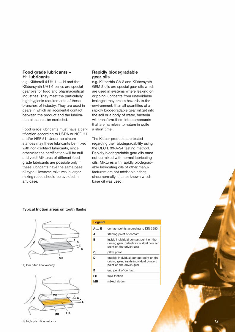
A … E contact points according to DIN 3980
A starting point of contact
B inside individual contact point on the driving gear, outside individual contactpoint on the driven gear
C pitch point
D outside individual contact point on the driving gear, inside individual contact point on the driven gear
E end point of contact
FR fluid friction
MR mixed friction
AB
CE
MR
MR
MR
FR
AB
C E
a) low pitch line velocity
Typical friction areas on tooth flanks
b) high pitch line velocity

14
Compared to mineral oils, syntheticgear oils provide clear advantages,not only from the technical, but alsofrom the economical and ecologicalpoint of view. The main benefits are:
– Reduction of the power loss thanksto a decrease of friction
– Increased gear efficiency– Lower operating temperatures– 3 to 5 times longer oil life depend-
ing on the base oil type– Energy cost savings– Cost savings regarding main-
tenance and disposal– Higher power can be transmitted
as oil withstands higher operatingtemperatures
Which synthetic oil type is suited best for a changeover should not be decided by the end user alone. On principle, this should always be agreed together with the gear and/or equipment manufacturer. The selection diagrams 1 to 3 providea general overview of the syntheticgear oils offered by Klüber as well astheir main fields of application.
Changeover frommineral oil to syntheticoil lubrication
Measurements of the spur teeth (involute gear)
a centre distance
c tip clearance
g� length of path of contact A - B - C
� action angle
p pitch
A start of contact
B inside individual contact point: leading gear is just leaving the contact area (point E)
C pitch point
D outside individual contact point: trailing gear is just entering the contact area. For gear 2, B is the outside individual contact point
Legend

When changing over to ester-basedKlüberbio lubricating oils, the materi-als used for seals, paints and inspec-tion glasses should be known in orderto reliably exclude any interactionbetween these and the lubricating oil.
To make use of the special charac-teristics of the Klüberbio oils rightfrom the beginning and to avoid geardamage and its consequences, youshould read our product informationfor the appropriate Klüberbio oilscarefully and follow the correspondinginstructions.
The required product information isavailable on www.klueber.com or canbe requested to be sent by mail freeof charge.
15
PAO oils – lubricating oils based onsynthetic hydrocarbon oils – have achemical structure similar to that ofmineral oils. As a rule, their compati-bility with seal materials and lacquerscorresponds to that of mineral oils.They also should be disposed of orrecycled in the same way and theymay be mixed with mineral oil residues. With selected base oils and accordingly matched additives, PAO oils are also suitable for producing lubricants such as the Klüberoil 4 UH 1- ... N oils for use inthe food and pharmaceutical indus-tries. However, in order to avoid anullification of the food law certifica-tion of such lubricants, food gradelubricants must never be mixed withnon-certified mineral oils.
The required product information isavailable on www.klueber.com or canbe requested to be sent by mail free of charge.
Changeover to polyalphaolefin (PAO) oils
Klübersynth GEM 4- .... N and Klüberoil 4 UH1 ... N oils
Changeover to polyglycol (PG) oils
Klübersynth GH 6 and Klübersynth UH1 6 oils
Changeover to ester oils
Klüberbio CA 2 and Klübersynth GEM 2 oils
When changing over to PG oils – lubricating oils based on poly-glycols – the materials used for seals,paints and inspection glasses shouldbe known in order to reliably excludeany interaction between these and the lubricating oil.
To make use of the high performanceof the Klüber PG oils right from thebeginning and to avoid gear damageand its consequences, you shouldread our product information for theappropriate PG lubricating oil seriescarefully and follow the correspondinginstructions.
With selected base oils and accord-ingly matched additives, PG oils arealso suitable for producing lubricantssuch as the Klübersynth UH1 6 oils foruse in the food and pharmaceuticalindustries. However, in order to avoida nullification of the food law certifica-tion of such lubricants, food gradelubricants must never be mixed withnon-certified lubricants.
The required product information isavailable on www.klueber.com or canbe requested to be sent by mail freeof charge.

16

17
The changeover from mineral oil tosynthetic oil should be performed with utmost care. It might perhaps benot enough to only drain off the usedmineral oil and refill new synthetic oil.
Particularly when dealing with oldergear units, it can be assumed that oil residues have collected in the gearbox, in oil pipings etc., which may be dissolved and separated by all types of synthetic oils.
If such residues are not removed, they may lead to gear damage duringlater operation. Oil pipings and filterswill be clogged, seals, pumps andgears will get damaged. In order toavoid damage, you should first drainthe oil at operating temperature, ifpossible, and then flush the gear orclosed lubricating system using thesynthetic oil type to be filled later. When switching over to food gradelubricants or bio-lubricating oils suchas Klüberoil 4 UH1- … N oils or
How to proceed with oil changes
Klüberbio oils, the flushing processshould be repeated once or twice inorder to ensure that all mineral oilresidues, which might affect the spe-cial characteristics (food grade safety,rapid biodegradability) of such lubri-cating oils, have been removed.
The synthetic oil used for flushingmust not be used for lubrication after-wards, however, it may be kept andused for further flushing processes.Note that prior to filling in the freshsynthetic oil, the oil filter(s) and filterinserts need to be exchanged.

18
Are you interestedin detailed information regarding our range of products?
Do you requiresafety data sheets of the products mentioned?
Then ordervia our website www.klueber.com.

19
Publisher and Copyright:Klüber Lubrication München KG
Reprints, total or in part, are permitted if source is indicated andvoucher copy is forwarded.
9.3.1 eEdition 03.08, replaces edition 04.05
The data in this technical brochure isbased on our general experience andknowledge at the time of printing andis intended to give information ofpossible applications to a reader withtechnical experience. It constitutesneither an assurance of productproperties nor does it release the user from the obligation of performingpreliminary tests with the selectedproduct. We recommend contactingour Technical Consulting Staff todiscuss your specific application. If required and possible we will be pleased to provide a sample for testing.
Klüber products are continually im-proved. Therefore, Klüber Lubricationreserves the right to change all thetechnical data in this technical brochure at any time without notice.

We are where you are.
Klüber Lubrication – the world market leader in speciality lubricants
• subsidiaries in over 30 countries• more than 1,700 staff• products available worldwide
Klüber Lubrication offers expert tribological solutions. Through our worldwide presence, we meet customers’ needs reliably and on time. We supply tailor-made speciality lubricants to customers from nearly all branches of industry and around the world – oils, greases, bonded coatings, pastes and many more. Over 75 years of experience, industry-specific know-how, and exceptional test facilities all help to optimise our solutions.
Klüber Lubrication München KGA company of the Freudenberg Group www.klueber.com