Gearbox designs for the diamond anvil cell: Applications ...paul/images/Gearbox.pdf · FIG. 2....
5
PV
Transcript of Gearbox designs for the diamond anvil cell: Applications ...paul/images/Gearbox.pdf · FIG. 2....

Gearbox designs for the diamond anvil cell: Applications to hard-to-reach
placesPaul B. Ellison,1, a) Dean Smith,1 Stanislav V. Sinogeikin,2 and Ashkan Salamat1, b)1)Department of Physics & Astronomy & HiPSEC, University of Nevada Las Vegas, Las Vegas, Nevada 89154, USA2)DAC Tools LLC, Naperville, Illinois 60565, USA
(Dated: 20 June 2019)
The uniaxial compression design of the diamond anvil high pressure cell (DAC) necessitatesthe use of a soft pressure-transmitting medium (PTM) to minimize non-hydrostatic e�ectsat signi�cantly high pressures, and many such media are gaseous at ambient conditions.There now exist a number of commercially-available instruments � high-pressure gas loadingapparatus � for the insertion of gases into the diamond anvil cell up to several kbar. Thesemachines allow the use of gases as a PTM, as a reagent for high-pressure chemistry, or to beloaded as the sample material itself. We present the development of two highly adaptablegearbox designs to allow the controlled closure of the DAC within an atmosphere of gasat several kbar, contained within the walls of a pressure vessel. The �rst applies a torquedirectly to the pressure screws and is thus DAC-speci�c, while the second applies a load tothe body of the cell and may be used with a wide variety of DAC designs.
I. INTRODUCTION
A myriad of diamond anvil cell (DAC) designs exist,often tailored to speci�c measurements. In many exper-iments, there is a necessity to load materials into theDAC which are gaseous at ambient conditions. Theseexperiments may be in study of the gas itself under ex-treme conditions,1,2 may utilize the gas as a reagent for anovel chemical reaction only accessible at extreme pres-sures,3,4 or bene�t from the use of the gas as a pressure-transmitting medium (PTM) � a material which remainssoft into the solid phase and encapsulates the sample,acting to reduce non-hydrostatic stresses in the sampleand compensating for the uniaxial compression inherentto the design of the DAC.5�8 A common method towardsthe insertion of these gases into the DAC is the use of ahigh-pressure gas loading apparatus, in which the DACis contained within a vessel and pressurized to the kbarregime whilst open, and the subsequent closure of theDAC in this environment traps high-pressure gas withinthe DAC sample chamber. This provides a high start-ing gas density for the experiment, before any load isapplied by the diamonds. Crucially, this avoids a signi�-cant portion of the volume collapse in the gas by havingthe experiment begin some distance along its P�V equa-tion of state, thereby reducing the amount of deformationon the sample chamber throughout the high-pressure ex-periment.The closure of the DAC within the high-pressure gas
loading apparatus thus presents an engineering challenge� how does one apply a controlled load to the DAC whencon�ned within the thick (typically several inches) wallsof a pressure vessel? Here, we describe the design oftwo gearboxes tailored to the closure of a diamond anvilhigh-pressure cell during the gas loading procedure: Onedesign that mates with a speci�c DAC geometry, and
a)Electronic mail: [email protected])Electronic mail: [email protected]
a second which may be used to close DACs of variousdesigns.
II. DAC-SPECIFIC GEARBOX
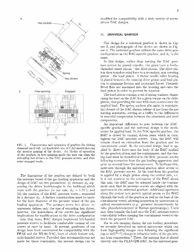
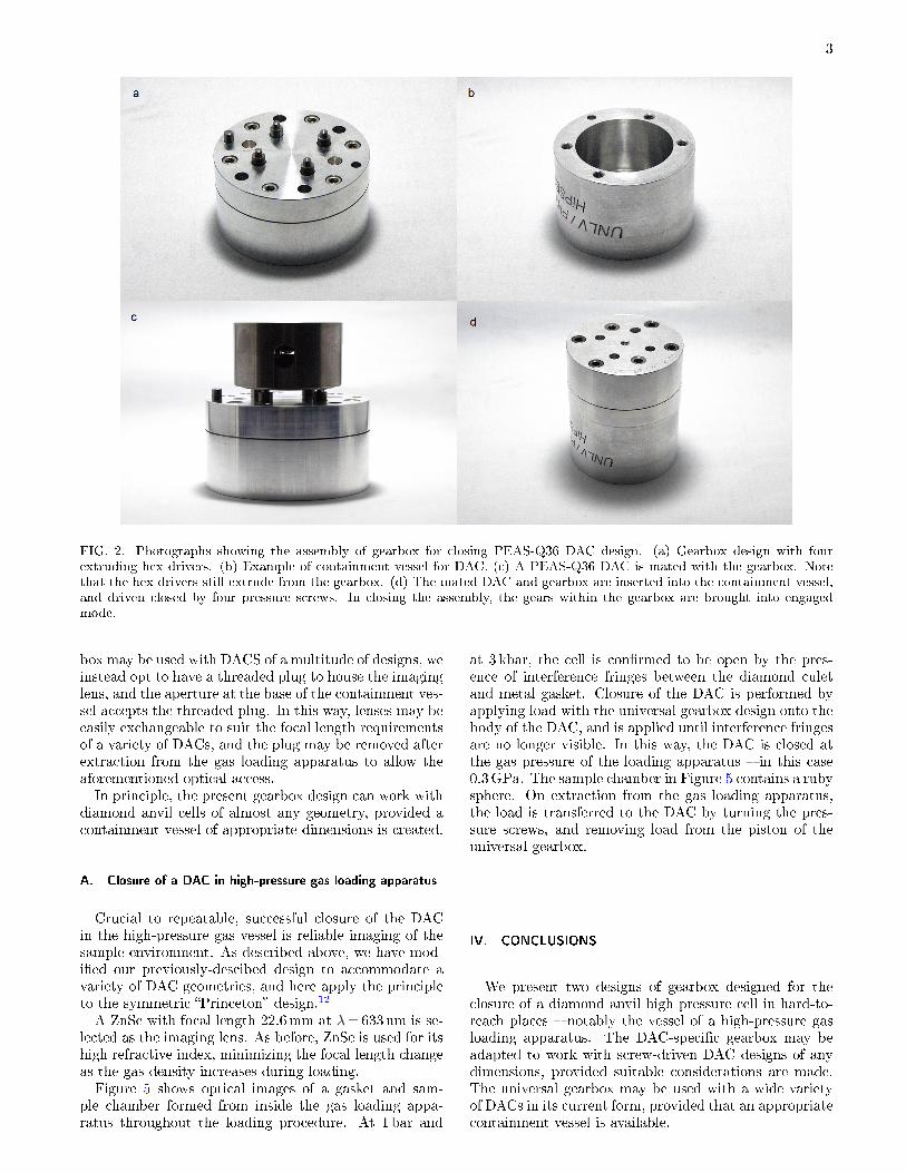
The gearbox design is shown in Figure 1a and pho-tographs in Figure 2, with its geometry designed for thatof our in-house �PEAS-Q36� DAC design. A pair of hexsockets on the top of the device drive two pairs of hexdrivers on the bottom, which apply torque to the DACpressure screws. The hex sockets on the top of the deviceare aligned to match the mechanical feedthroughs fromthe bulkhead of a high-pressure gas loading apparatus.9
The gears consist of 2 drive gears, which are manuallyturned through the bulkhead, and 4 driven gears whichturn the DAC pressure screws. The gearing is con�guredat 1:1 ratio. The 4 driven gears are sprung, allowing thedevice to switch between two modes � free-spinning andengaged. When not in contact with the DAC pressurescrews, springs push the 4 driven gears out of engage-ment from the 2 drive gears. This also causes the hexdrivers to greatly protrude from the face of the gear box,providing visual con�rmation of disengagement.
Figure 1b shows the two modes of operation of thegearbox design. In free-spinning mode, the extrudinghex drivers (attached to the driven gears) may be manu-ally turned to align each with the pressure screws on theDAC. Once each hex driver is aligned with the DAC pres-sure screws, the gearbox may be pushed down to engagethe gears and seal the containment vessel. The additionof free-spinning mode thus allows ease of alignment ofthe gearbox for quick assembly of the gearbox and con-tainer, allowing the positions of the DAC pressure screwsto remain untouched throughout the assembly procedure� an often crucial consideration, for instance in the caseof an experiment concerning an air-sensitive sample ina hermetically-sealed DAC. Furthermore, the travel onthe gearbox between free-spinning and engaged modesensures that the containment may not be closed withouteach hex driver engaged with a pressure screw.
2
a
b Free-spinning Engaged
dG
dD
Hex drivers
Spring
Hex sockets
FIG. 1. Construction and operation of gearbox for closingdiamond anvil cell. (a) Exploded view of CAD model showingthe interior gearing of the device. (b) Modes of operationof the gearbox, in free-spinning mode the user can align theextruding hex drivers to the DAC pressure screws, and thenenter engaged mode.
The dimensions of the gearbox are de�ned by boththe pressure vessel of the gas loading apparatus and thedesign of DAC via two parameters: (i) distance dG sep-arating the driver feedthroughs in the bulkhead whichmate with the gearbox (in our case, dG = 1.75”), and(ii) the position of the DAC pressure screws, separatedby a distance dD. A further consideration must be madefor the bore diameter of the pressure vessel of the gasloading apparatus. The pressure screw hex driver re-quirement de�nes only the size of extruding hex driver,however, The handedness of the screws has signi�cantimplications for modi�cations to the drive con�guration� note that many DAC designs implement left-handedpressure screws to facilitate comfortable turning of twoscrews at once by hand. At present, gearboxes of ourdesign have been constructed for compatibility with thePEAS and the BX-90 DAC, both of which feature onlyright-handed screws. Provided that accommodations aremade for these constraints, the present design can be
modi�ed for compatibility with a wide variety of screw-driven DAC designs.
III. UNIVERSAL GEARBOX
Our design for a universal gearbox is shown in Fig-ure 3, and photographs of the device are shown in Fig-ure 4. The universal gearbox utilizes the same drive gearcon�guration as the DAC-speci�c gearbox, and dG is thesame.
In this design, rather than turning the DAC pres-sure screws by geared transfer, the gears turn a �nely-threaded center piston � the drive piston. The drive pis-ton then transfers axial force to a secondary, non-rotatingpiston � the load piston. A thrust needle roller bearingis placed between the rotating drive piston and load pis-ton to minimize friction and rotational forces. Precisely�tted �ats are machined into the housing and onto theload piston in order to prevent its rotation.
The load piston contains a set of spring washers, damp-ening the load on the DAC for a given torque on the drivepiston, thus providing the user with more control over theapplied load. The spring washers also assist in maintain-ing closure of the DAC during release of gas from the gasloading apparatus, serving as a bu�er to the di�erencesin material compression between the aluminum and steelcomponents.
An important di�erence to note between the DAC-speci�c gearbox and the universal design is the mech-anism for applied load. In the DAC-speci�c gearbox, theDAC is closed by turning driven gears which in turn,tighten the DAC pressure screws. Thus, the DAC willremain closed on extraction from the gearbox and itscontainment vessel. In the universal design, load is ap-plied by direct force onto the body of the DAC appliedby the gearbox piston and the containment, and the clos-ing load must be transferred to the DAC pressure screwsfollowing extraction from the gas loading apparatus, andprior to removal from the containment. To facilitate this,apertures through the universal gearbox allow access tothe DAC pressure screws. As the load from the gearboxis applied by a single piston along the central axis, i.e.
it is not sensitive to the orientation of the DAC aboutthis axis, the DAC may be oriented inside the contain-ment such that its pressure screws are aligned with theapertures in the universal gearbox. Additional aperturesalong the central axis permit optical access to the DACthrough the body of the gearbox as well as the base of thecontainment vessel, allowing inspection by microscope oroptical measurements (e.g. pressure measurements byruby photoluminescence or Raman spectroscopy). Usersmay then transfer the load onto the DAC pressure screwscontrollably before opening the containment vessel to ex-tract the prepared DAC.
For in situ imaging during the gas loading procedure,we recently described an optical microscope which canform high-quality images even following the signi�cant(up to 20%10,11) change in refractive index of the gas aris-ing from compression.9 There, the imaging lens is placeddirectly onto the PEAS-Q36 DAC. As the universal gear-
3
FIG. 2. Photographs showing the assembly of gearbox for closing PEAS-Q36 DAC design. (a) Gearbox design with fourextruding hex drivers. (b) Example of containment vessel for DAC. (c) A PEAS-Q36 DAC is mated with the gearbox. Notethat the hex drivers still extrude from the gearbox. (d) The mated DAC and gearbox are inserted into the containment vessel,and driven closed by four pressure screws. In closing the assembly, the gears within the gearbox are brought into engagedmode.
box may be used with DACS of a multitude of designs, weinstead opt to have a threaded plug to house the imaginglens, and the aperture at the base of the containment ves-sel accepts the threaded plug. In this way, lenses may beeasily exchangeable to suit the focal length requirementsof a variety of DACs, and the plug may be removed afterextraction from the gas loading apparatus to allow theaforementioned optical access.In principle, the present gearbox design can work with
diamond anvil cells of almost any geometry, provided acontainment vessel of appropriate dimensions is created.
A. Closure of a DAC in high-pressure gas loading apparatus
Crucial to repeatable, successful closure of the DACin the high-pressure gas vessel is reliable imaging of thesample environment. As described above, we have mod-i�ed our previously-descibed design to accommodate avariety of DAC geometries, and here apply the principleto the symmetric �Princeton� design.12
A ZnSe with focal length 22.6mm at λ=633 nm is se-lected as the imaging lens. As before, ZnSe is used for itshigh refractive index, minimizing the focal length changeas the gas density increases during loading.Figure 5 shows optical images of a gasket and sam-
ple chamber formed from inside the gas loading appa-ratus throughout the loading procedure. At 1 bar and
at 3 kbar, the cell is con�rmed to be open by the pres-ence of interference fringes between the diamond culetand metal gasket. Closure of the DAC is performed byapplying load with the universal gearbox design onto thebody of the DAC, and is applied until interference fringesare no longer visible. In this way, the DAC is closed atthe gas pressure of the loading apparatus � in this case0.3GPa. The sample chamber in Figure 5 contains a rubysphere. On extraction from the gas loading apparatus,the load is transferred to the DAC by turning the pres-sure screws, and removing load from the piston of theuniversal gearbox.
IV. CONCLUSIONS
We present two designs of gearbox designed for theclosure of a diamond anvil high pressure cell in hard-to-reach places � notably the vessel of a high-pressure gasloading apparatus. The DAC-speci�c gearbox may beadapted to work with screw-driven DAC designs of anydimensions, provided suitable considerations are made.The universal gearbox may be used with a wide varietyof DACs in its current form, provided that an appropriatecontainment vessel is available.

4
a
b
No load Load
dG
Drive piston
Load piston
DAC screwaperture
Springwashers
FIG. 3. Construction and operation of universal gearboxfor closing a diamond anvil cell. (a) Exploded view of CADmodel, (b) Operation of universal gearbox, showing action oftop screws to drive the piston.
V. SUPPLEMENTAL MATERIAL
Two SolidWORKS assemblies are available as Supple-mental Material: (i) DAC-speci�c gearbox with dimen-sions dG and dD discussed here, (ii) universal gearboxdesign with dG presented here. Each are available aszipped folders containing the assembly and all necessaryparts.
ACKNOWLEDGMENTS
The authors thank David P. Shelton.
1P. Loubeyre, R. LeToullec, D. Hausermann, M. Han�and, R. J.Hemley, H. K. Mao, and L. W. Finger, Nature 383, 702 (1996).
2F. Datchi, B. Mallick, A. Salamat, and S. Ninet, Physical ReviewLetters 108, 125701 (2012).
3A. Salamat, A. L. Hector, B. M. Gray, S. A. J. Kimber, P. Bou-vier, and P. F. McMillan, Journal of the American ChemicalSociety 135, 9503 (2013).
4E. Stavrou, S. Lobanov, H. Dong, A. R. Oganov, V. B.Prakapenka, Z. Konôpková, and A. F. Goncharov, Chemistryof Materials 28, 6925 (2016).
5M. I. McMahon, in High-Pressure Crystallography, NATO Sci-ence Series (Series II: Mathematics, Physics and Chemistry),
FIG. 4. The universal gearbox for closing DACs of variousdesign. (a) The load piston remains �ush with the bottom ofthe gearbox during assembly. (b) On turning the hex socketson the top face of the gearbox, the load piston extrudes fromthe gearbox to exert force onto the DAC.
FIG. 5. Closure of a Princeton-type symmetric DAC by theuniversal gearbox during high-pressure gas loading of He at3 kbar. The DAC is �tted with diamonds with �=500µmculets, and a stainless steel gasket with a �=280µm samplechamber containing a ruby sphere. The disappearance of in-terference fringes between the gasket material and diamondsignify the closure of the DAC.

5
Vol. 140, edited by A. Katrusiak and P. F. McMillan (Springer,Dordecht, Netherlands, 2004) pp. 1�20.
6A. Dewaele and P. Loubeyre, High Pressure Research 27, 419(2007).
7K. Takemura and A. Dewaele, Physical Review B 78, 104119(2008).
8S. Klotz, J.-C. Chervin, P. Munsch, and G. L. Marchand, Journalof Physics D: Applied Physics 42, 075413 (2009).
9D. Smith, D. P. Shelton, P. B. Ellison, and A. Salamat, Reviewof Scienti�c Instruments 89, 103902 (2018).
10A. Dewaele, J. H. Eggert, P. Loubeyre, and R. L. Toullec, Phys-ical Review B 67, 094112 (2003).
11G. J. Hanna and M. D. McCluskey, Physical Review B 81, 132104(2010).
12H. K. Mao, G. Shen, R. J. Hemley, and T. S. Du�y, in Prop-
erties of Earth and Planetary Materials at High Pressure and
Temperature, edited by M. H. Manghnani and T. Yagi (Ameri-can Geophysical Union, 1998).