Gear
23
Gear Gear
-
Upload
yogendra-singh-shekhawat-rajnota -
Category
Engineering
-
view
405 -
download
5
description
Gear? Where it is used and why? We know that gear is power transmitting element but there are many any elements like - rope, chain drives which can also be used. There are many benefits of using gear over belt, rope, chain drive, that's why we used gear. Here we provide a complete description about gear, types of gear. Spur gear, Helical gear, Worm gear, Bevel gear, these are some important types of gear which are described briefly with their terminology. A complete difference is clarified between all types of gear relating their shapes and position of shaft.
Transcript of Gear

Gear
Gear
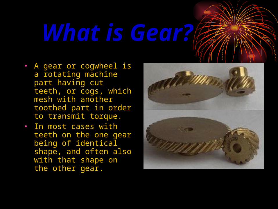
What is Gear?• A gear or cogwheel is a
rotating machine part having cut teeth, or cogs, which mesh with another toothed part in order to transmit torque.
• In most cases with teeth on the one gear being of identical shape, and often also with that shape on the other gear.

Types of Gears1. According to the position of axis
of the shafts -
(a.) Parallel
(b.) Intersecting
(c.) Non-Intersecting and non-parallel

(a.) Parallel and co-planar shafts
(i) Spur Gear -They consist of a cylinder or disk with the teeth projecting radially.
(ii) Helical Gear-The leading edges of the teeth are not parallel to the axis of rotation, but are set at an angle.
Spur Gear
Helical Gear

(b.) Intersecting/ non-parallel and Co-planer Shaft
• Bevel Gear - Two non-parallel and intersecting, but co-planer shafts are connected by the bevel gear and the arrangement is called bevel gearing.
• Bevel gears, like spur gears may also have their teeth inclined to the face of the bevel, in this case they are known as helical bevel gears.
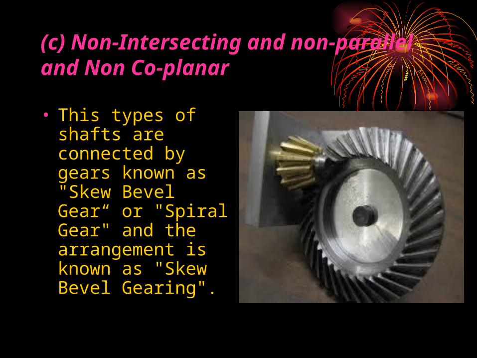
(c) Non-Intersecting and non-parallel and Non Co-planar
• This types of shafts are connected by gears known as "Skew Bevel Gear“ or "Spiral Gear" and the arrangement is known as "Skew Bevel Gearing".

2. According to the Peripheral Velocity of the Gears
(a.) Low Velocity ( Less than 3 m / s )
(b.) Medium Velocity ( 3-15 m / s )
(c.) High Velocity ( Greater than 15 m / s )

3. According to Type of Gearing
(a.) External Gearing
(b.) Internal Gearing
(c.) Both Internal and External

(a.) External Gearing
• In external Gearing, the two shafts mesh externally with each other.
• The larger of two wheels is wheel or Gear and the smaller wheel is called pinion.
• In an external gearing, the motion of the two wheels is always unlike or opposite.
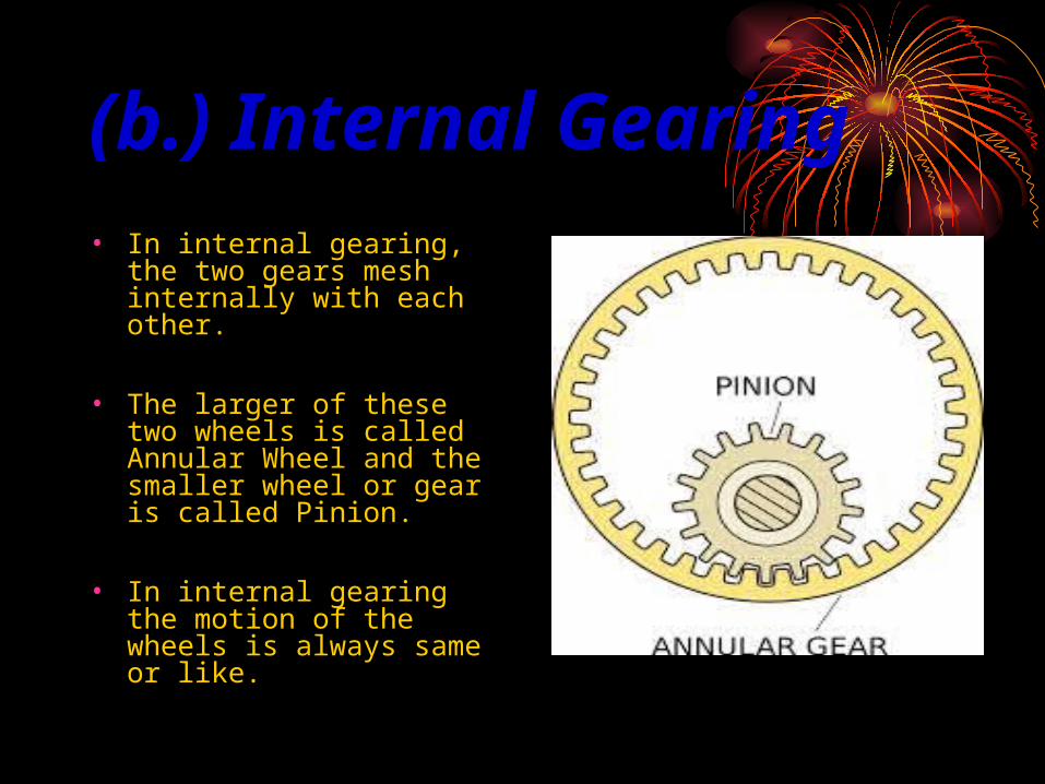
(b.) Internal Gearing• In internal gearing, the
two gears mesh internally with each other.
• The larger of these two wheels is called Annular Wheel and the smaller wheel or gear is called Pinion.
• In internal gearing the motion of the wheels is always same or like.

(c.) Both Internal and External• The gear of two shaft
meshes externally and internally with the gears in a straight line. Such type of gear is called Rack and Pinion.
• The straight line gear is called Rack and the circular wheel is called Pinion.
• With the help of Rack and Pinion we can convert Linear motion into rotary motion and vice-versa.

4. According to the Position of Teeth on the Gear Surface
• (a.) Straight
• (b.) Inclined
• (c.) Curved

Some Important Terminology of Spur Gear

• 1. Pitch Circle : - It is an imaginary circle which by pure rolling action, would give the same motion as the actual gear.
• 2. Pitch Circle Diameter : - It is the diameter of the pitch circle.
• 3. Pitch Point : - It is a common point of contact between two pitch circles.
• 4. Pitch surface : - The surface of the imaginary rolling cylinder (cone, etc.) that the toothed gear may be considered to replace.
• 5. Addendum circle : - A circle bounding the ends of the teeth, in a right section of the gear.
• 6. Root (or dedendum ) circle : - The circle bounding the spaces between the teeth, in a right section of the gear.
• 7. Addendum : - The radial distance between the pitch circle and the addendum circle.
• 8. Dedendum : - The radial distance between the pitch circle and the root circle.

11. Flank of a tooth : - The part of the tooth surface lying inside the pitch surface.
12. Circular thickness ( also called the tooth thickness ) : The thickness of the tooth measured on the pitch circle. It is the length of an arc and not the length of a straight line.
13. Tooth space : - The distance between adjacent teeth measured on the pitch circle.
14. Backlash : - The difference between the circle thickness of one gear and the tooth space of the mating gear.
Backlash = Space width – Tooth thickness
15. Circular pitch (Pc) : - The width of a tooth and a space, measured on the pitch circle or it is the distance measured on the circumference of the pitch circle from a point of one tooth to the corresponding point on the next tooth.
16. Diametral pitch (Pd) : - The number of teeth of a gear per inch of its pitch diameter. A toothed gear must have an integral number of teeth. The circular pitch, therefore, equals the pitch circumference divided by the number of teeth. The diametral pitch is, by definition, the number of teeth divided by the pitch diameter.
17. Module (m) : - Pitch diameter divided by number of teeth. The pitch diameter is usually specified in inches or millimetres; in the former case the module is the inverse of diametral pitch.

Helical Gear Terminology
1. Helix Angle : - Angle between a tangent to the helix and the gear axis. It is zero in the limiting case of a spur gear, albeit it can considered as the hypotenuse angle as well.
2. Axial Pitch : - It is the distance, parallel to the axis, between similar face of adjacent teeth. It is the same as circular pitch and denoted by Pc.
3. Normal Pitch : - It is the distance between similar faces of adjacent teeth along a helix on the pitch cylinders normal to teeth. It is denoted by Pn.

Worm Gear• Worm gears
resemble screws. A worm gear is usually meshed with a spur gear or a helical gear, which is called the gear, wheel, or worm wheel.
• To achieve a high torque, low speed gear ratio.

Worm Gear Terminology
1. Lead : - Distance from any point on a thread to the corresponding point on the next turn of the same thread, measured parallel to
the axis.
2. Linear Pitch ( p ) : - Distance from any point on a thread to the corresponding point on the adjacent thread, measured parallel to
the axis. For a single-thread worm, lead and linear pitch are the same.
3. Lead Angle : - Angle between a tangent to the helix and a plane perpendicular to the axis. Note that it is the complement of the
helix angle which is usually given for helical gears.
4. Tooth Pressure Angle : - It is the measured in a plane containing the axis of the worm gear and is equal to one-half the thread profile.
5. Normal Pitch : - It is the distance measured along the normal to the threads between two corresponding points on two adjacent threads of the worm.
6. Helix Angle : - It is the angle between the tangent to the thread helix on the pitch cylinder and the axis of the worm.
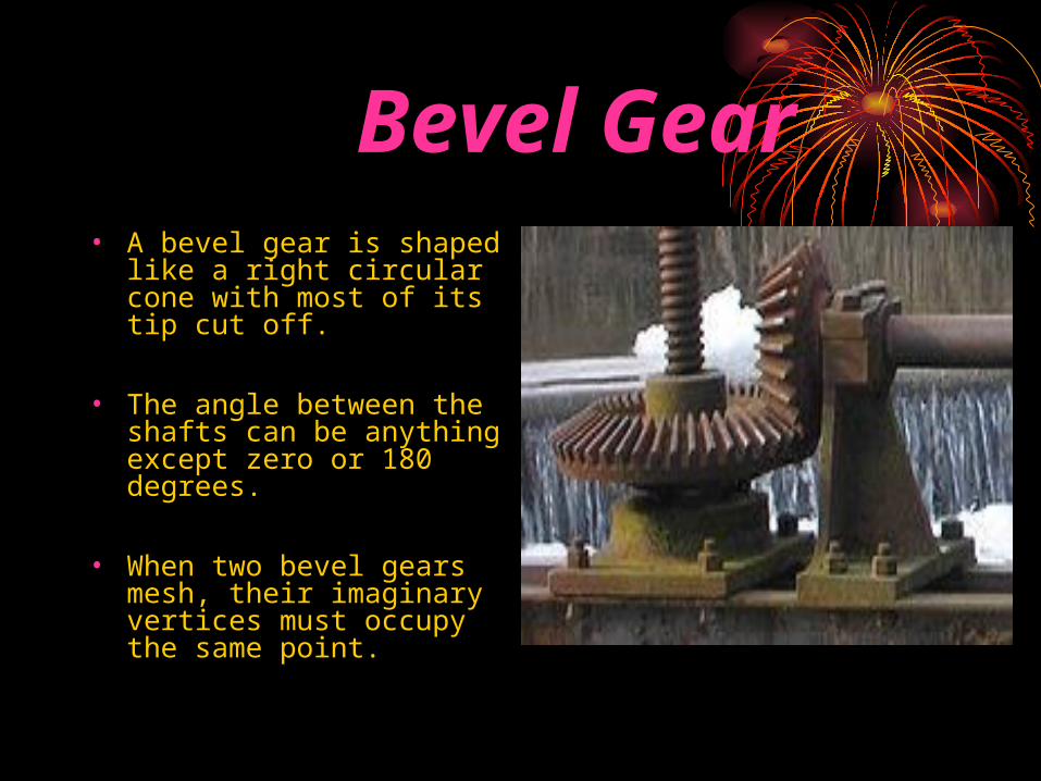
Bevel Gear • A bevel gear is shaped
like a right circular cone with most of its tip cut off.
• The angle between the shafts can be anything except zero or 180 degrees.
• When two bevel gears mesh, their imaginary vertices must occupy the same point.

Spiral Bevels
• Spiral bevel gears have the same advantages and disadvantages relative to their straight-cut cousins as helical gears do to spur gears.
• Straight bevel gears are generally used only at speeds below 5 m / s (1000 ft/min), or, for small gears, 1000 r.p.m.

Bevel Gear Terminology 1. Pitch Cone : - It is the cone containing the pitch elements of the teeth.
2. Cone Centre : - It is the apex of pitch cone. It may be defined as that point where the axis of two mating gears intersect each-other.
3. Pitch Angle : - It is the angle made by the pitch line with the axis of shaft.
4. Cone Distance : - It is the length of pitch cone element. It is also called as a Pitch Cone Radius.
5. Addendum Angle : - It is the angle subtended by the addendum of the tooth at the cone centre.
6. Dedendum Angle : - It is the angle subtended by the dedendum of the tooth at the cone centre.
7. Face Angle : - It is the angle subtended by the face of tooth at the cone centre. It is equal to pitch angle plus addendum angle.
8. Root Angle : - It is the angle subtended by the root of the tooth at the cone centre. It is equal to the pitch angle minus dedendum angle.
9. Back Cone : - It is the imaginary cone, perpendicular to the pitch cone at the end of the tooth.
10. Back Cone Distance : - It is the length of the back cone.
11. Backing : - It is the distance of the pitch point from the back of the boss, parallel to the pitch point of the gear.

For more visit
www.studyhubz.comA power point presentation by Yogendra Singh Shekhawat B. Tech, Mechanical Engineering