Gear pump unit Product series KFB - SKF.com12-74813/1-1206-EN.pdf · Gear pump unit Product series...
12
Gear pump unit Product series KFB For high-viscosity oils and fluid grease of NLGI grades 000, 00 For use in SKF MonoFlex single-line centralized lubrication systems SKF gear pump units of the KFB product se- ries are used to supply lubricant to SKF MonoFlex single-line systems. They are de- signed for use on commercial vehicles, sys- tems, and machines. The commercial vehicle version has type approval pursuant to ECE-R 10. SKF gear pump units of the KFB product series are designed for the supply of fluid grease of NLGI grades 000 and 00. They in- clude a pressure-relief valve and a pres- sure-limiting valve for the operation of in- termittently operated MonoFlex single-line systems. The distribution and metering of the lubricant to the lubrication point can be accomplished using SKF MonoFlex single- line distributors. The gear pump units are designed for supply voltages of 12 V DC and 24 V DC . They are controlled either by a built-in electronic con- trol unit or externally, via the machine control system. An optional fill level switch can be se- lected to monitor the fill level. Depending on the design, the gear pump units are filled via a filler socket or an attached filler coupling. Their compact design makes gear pump units of the KFB product series the ideal so- lution for the assembly of small centralized lubrication systems on commercial vehicles and machines with few lubrication points.
Transcript of Gear pump unit Product series KFB - SKF.com12-74813/1-1206-EN.pdf · Gear pump unit Product series...
Gear pump unit
Product series KFBFor high-viscosity oils and fluid grease of NLGI grades 000, 00 For use in SKF MonoFlex single-line centralized lubrication systems
SKF gear pump units of the KFB product se-
ries are used to supply lubricant to SKF
MonoFlex single-line systems. They are de-
signed for use on commercial vehicles, sys-
tems, and machines. The commercial vehicle
version has type approval pursuant to
ECE-R 10.
SKF gear pump units of the KFB product
series are designed for the supply of fluid
grease of NLGI grades 000 and 00. They in-
clude a pressure-relief valve and a pres-
sure-limiting valve for the operation of in-
termittently operated MonoFlex single-line
systems. The distribution and metering of
the lubricant to the lubrication point can be
accomplished using SKF MonoFlex single-
line distributors.
The gear pump units are designed for supply
voltages of 12 V DC and 24 V DC . They are
controlled either by a built-in electronic con-
trol unit or externally, via the machine control
system. An optional fill level switch can be se-
lected to monitor the fill level. Depending on
the design, the gear pump units are filled via
a filler socket or an attached filler coupling.
Their compact design makes gear pump
units of the KFB product series the ideal so-
lution for the assembly of small centralized
lubrication systems on commercial vehicles
and machines with few lubrication points.

PUB LS/P2 12658 EN · 1-1206-EN
Product series KFB
Product overview
KFBS1 with integrated control KFBS1-6-S1 with VN relubrication distributor
SKF gear pump units of the KFB product se-
ries differ principally in their options for
electrical connection and in control and
function monitoring.
The pump casing contains the mounting
flange, the mounting plate for the hydraulic
connections, the electrical connection, and
in the case of controlled models, also the
display screen of the electronic control unit
built into the pump casing.
Gear pump units of the KFB1 group are
not controlled and therefore do not contain
a built-in control unit. Gear pump units of
the KFBS1 group contain an integrated elec-
tronic control unit that can be programmed
via the display screen on the front of the
pump casing. The electronic control unit
regulates the functions of the gear pump
unit and monitors the fill level. If available,
an external pressure switch can also be in-
tegrated into the monitoring system.
The mounting plate for the hydraulic con-
nections includes the pressure-limiting
valve, the pressure-relief valve, and the lu-
brication line connection. For models with a
follower piston, there is always a filler cou-
pling fitted on the mounting plate for filling
the lubricant reservoir. With models without
a follower piston, the lubricant reservoir can
also be filled directly through a filler socket
on the reservoir surface.
The lubricant reservoir is mounted on the
pump casing and is made of transparent
plastic with markings for visual monitoring
of the fill level. Models with automatic fill
level monitoring contain a fill level switch as
well, which is either separate in the lubricant
reservoir or acts together with the follower
piston to issue a signal when the lubricant
level is too low.
Gear pump units in the KFB1 group are
fitted with a pushbutton on the pump casing
for triggering interim lubrication. On gear
pump units of the KFBS1 group (controlled),
interim lubrication is triggered via the elec-
tronic control unit's display screen.
KFB1-M-W-S1KFB1-M-W KFBS1-M-W with integrated control
KFB1
2
PUB LS/P2 12658 EN · 1-1206-EN
Product series KFB
Product selection table
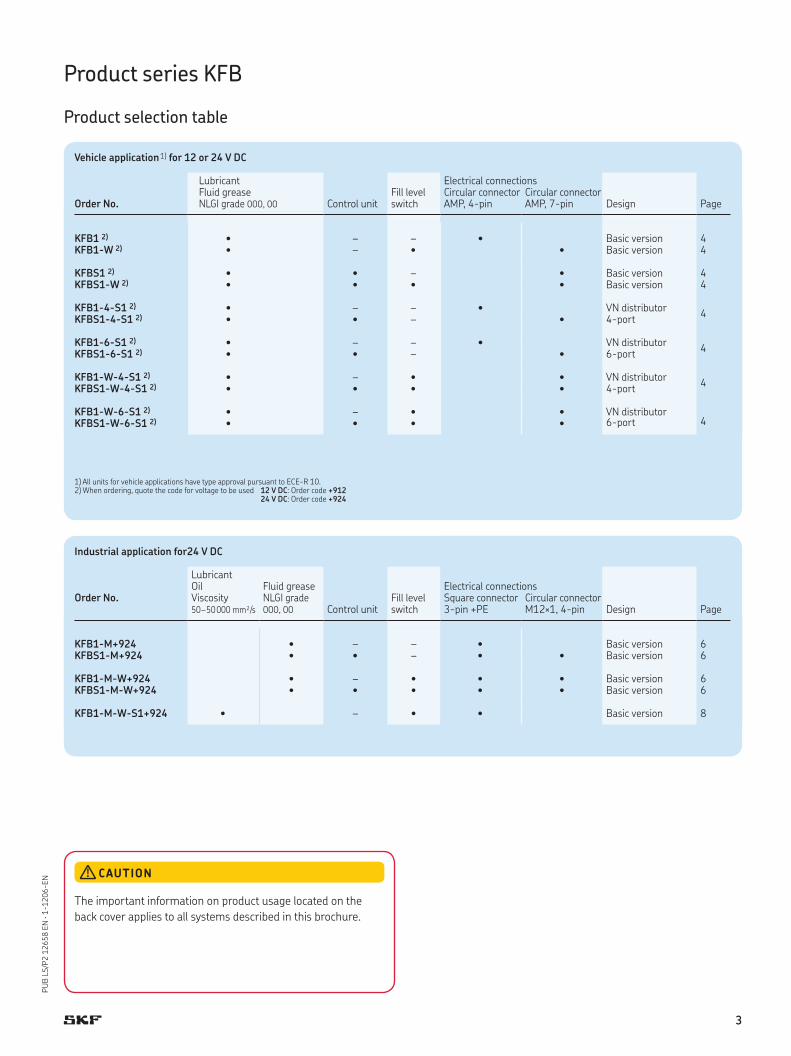
Vehicle application1) for 12 or 24 V DC
Lubricant Electrical connectionsFluid grease Fill level
switchCircular connector Circular connector
Order No. NLGI grade 000, 00 Control unit AMP, 4-pin AMP, 7-pin Design Page
KFB1 2) • – – • Basic version 4KFB1-W 2) • – • • Basic version 4
KFBS1 2) • • – • Basic version 4KFBS1-W 2) • • • • Basic version 4
KFB1-4-S1 2) • – – • VN distributor 4-port
4KFBS1-4-S1 2) • • – •
KFB1-6-S1 2) • – – • VN distributor 6-port
4KFBS1-6-S1 2) • • – •
KFB1-W-4-S1 2) • – • • VN distributor 4-port
4KFBS1-W-4-S1 2) • • • •
KFB1-W-6-S1 2) • – • • VN distributor 6-port 4KFBS1-W-6-S1 2) • • • •
1) All units for vehicle applications have type approval pursuant to ECE-R 10.2) When ordering, quote the code for voltage to be used 12 V DC: Order code +912
24 V DC: Order code +924
Industrial application for24 V DC
LubricantOil Fluid grease Electrical connections
Order No. Viscosity NLGI grade Fill level switch
Square connector Circular connector 50–50000 mm²/s 000, 00 Control unit 3-pin +PE M12×1, 4-pin Design Page
KFB1-M+924 • – – • Basic version 6KFBS1-M+924 • • – • • Basic version 6
KFB1-M-W+924 • – • • • Basic version 6KFBS1-M-W+924 • • • • • Basic version 6
KFB1-M-W-S1+924 • – • • Basic version 8
CAUTION
The important information on product usage located on the
back cover applies to all systems described in this brochure.
3

PUB LS/P2 12658 EN · 1-1206-EN
Product series KFB(S)1
Commercial vehicle applications
KFBS1
Diagram 1
Max. connected load / max. main line length for fluid grease of NLGI grades 000, 00
6
1 2 43
2
1
43
65 7 98
108
1412
16
max.-15°C
max.-25°C
10 11 12 13 14 15 16 17
Range of application
† Connected load of distributor [cm³]
† Ma
in li
ne
[m]
KFBS1-6-S1
M8
100
150
ø0.4
Fixing diagram
Drilling template
Technical data
Units KFB(S)1, KFB(S)1-W, KFB(S)1-4-S1, KFB(S)1-W-4-S1, KFB(S)1-6-S1, KFB(S)1-W-6-S1
Fill level switch (for KFB(S)1-W) (opens when fill level too low)
Switching voltage range . . . . . . . . 10 to 36 V DCReservoir capacity KFB(S)1-W . . . . 1 liter Switching current (resistive load)3) . . . ≤0.5 AReservoir capacity KFB(S)1 . . . . . . 1.4 liters Switching capacity (resistive load)3) . . ≤12 WDelivery rate1) . . . . . . . . . . . . 50 cm³/minMax. operating pressure . . . . . . . 38 bar Relubrication distributor VN (KFB(S)1(-W)4-S1, KFB(S)1(-W)-6-S1)Operating temperature . . . . . . . . –25 to +75 °C Lubrication point connection . . . . . Push-to-connect fitting for tube ø4Protection class according to DIN 40050 T9. . . . . . . . . . . . .
Metered quantity . . . . . . . . . . . 0.1; 0.2; 0.4 cm³IP6K6K / IP6K9K Feeder body . . . . . . . . . . . . . . Die-cast zinc, black corrosion
protectionNumber of outlets . . . . . . . . . . . 1Lubricant . . . . . . . . . . . . . . . Fluid grease of
NLGI grade 000 or 00Control unit IG502-2-I (KFBS1)Interval, adjustable . . . . . . . . . . 0.1 ... 99.9 h
Connected load . . . . . . . . . . . . See diagram 1 Pump run time, adjustable . . . . . . 0.1 ... 99.9 min
Main line . . . . . . . . . . . . . . . ø 10×1.5; max. 16 m see diagram
Max. pump run time . . . . . . . . . 3.0 min2)
Elapsed-hours counter . . . . . . . . 0 ... 99999.9 hDC motor Fault-hours counter . . . . . . . . . . 0 ... 99999.9 h
Rated voltage . . . . . . . . . . . . . 12 V 24 VRated current . . . . . . . . . . . . . 3.8 A 1.7 A Additional input power for units with
control unit (without output load) . . . . . . . . .
Rated output . . . . . . . . . . . . . 46 W 41 W 4 W
Operating mode acc. to DIN EN 60034-1 (VDE 0530-1)2) . . . S3, 2.5% (10 to 120 min)
1) At back pressure of 10 bar and a temperature of +25 °C.2) The operating mode S3 (periodic duty) describes the ratio of pump run time to subsequent down time. If the relative ON-time is 2.5% and the
duty cycle time is 10 to 120 min., then the limit values are as follows: Min. duty cycle time: 10 min×0.025 = 0.25 min. pump run time with subsequent down time of 9.75 min. Max. duty cycle time: 120 min×0.025 = 3 min. pump run time with subsequent down time of 117 min.
3) When switching inductive loads, take appropriate measures to protect contacts.
4

PUB LS/P2 12658 EN · 1-1206-EN
Product series KFB(S)1
Assembly drawing
P
70
~40
294
max
min
100
235
M16
x1.5
1)
ø9
216150 150
10
1 2
KFBS1 KFB1-W-4-S1 with control with pre-assembled VN relubrication distributor
3115
F
1)
4
BN
X1 1
BK
3
RD-B
K
2
2
4
3
1
2)
PK
+
–
M
M1DK
VN relubrication
distributor, 4-port
Metered quantity 1
SL2
2.4W
31 15
F
DK DS+ 2.4W
SL1
PK
4
BN
X1 1
BU
3
RD-B
K
2
BK
6
BK
5
VT-G
N
7
6
5
7
1 2
4 3
31 15
F
1)
PK
4
BN
X1 1
BU
3
RD-B
K
2 6
BK
5 7
+ OK
BK
VT-G
N
Q
WS
2) 2)
DKM1
+
–
M
KFB1: X1 circular plug 4-pin for cable harness
KFBS1: X1 circular plug, 7-pin for cable harness KFB1: pushbutton
1) Connection thread countersunk for solderless tube union for tube ø 10 mm.2) Coupling socket for filler socket, order no. 995-001-500 (must be ordered separately).
Filler socket 2)
P
Hydraulic layout KFB1
P
Hydraulic layout KFBS1-W
Vent plug
Push-to-connect fitting
connection for tube ø 4
Key to terminal diagrams 1–2
15 = + Supply voltage potential (ignition ON)
31 = – Supply voltage potential (0 V, ground)X1 = Plug-in connection 4-pin or 7-pinDK = Pushbutton WS = Fill level switch,
contacts shown for full reservoirDS = Pressure switch (external)SL1 = Indicator light “pump ON”SL2 = Indicator light “malfunction”F = Fuse protection to ISO 8820
for 24 V DC: 3 A for 12 V DC: 5 A
1) = External control, relay contact “pump ON”
2) = Pin without internal connection
Not used
Not used
Terminal diagram 1
X1 circular plug 4-pin Cable harness 997-000-706 (not included in delivery)
KFB1, KFB1-4-S1, KFB1-6-S1
Terminal diagram 2
X1 circular plug7-pin Cable harness 997-000-904, cable harness with corrugated tube 997-000-630 or 997-000-650 (not included in delivery)
KFBS1(-W) KFBS1(-W)-4-S1 KFBS1(-W)-6-S1
KFB1-W KFB1-W-4-S1 KFB1-W-6-S1
5

PUB LS/P2 12658 EN · 1-1206-EN
Product series KFB(S)1-M (-W)
Industrial applications
KFB1-M-W
Technical data
Units KFB1-M, KFB1-M-W, KFBS1-M, KFBS1-M-WReservoir capacity KFB1-M . . . . . . 1.4 liters Fill level switch (KFB1-M-W) (changeover contact)Reservoir capacity KFB(S)1-M(-W) . 1 liter Switching voltage range . . . . . . . . 24 V DC 3)
Delivery rate1) . . . . . . . . . . . . . 50 cm³/min Switching current (resistive load)4) . . . ≤0.5 AMax. operating pressure . . . . . . . 38 bar Switching capacity (resistive load)4) . . ≤12 WOperating temperature . . . . . . . . 0 to +60 °CProtection class according to DIN EN 60529 (VDE 0470-1) . . . . .
Control unit IG502-2-I (KFBS1)IP65 Interval, adjustable . . . . . . . . . . 0.1 ... 99.9 h
Operating mode acc. to DIN EN 60034-1 (VDE 0530-1)2) . . .
Pump run time, adjustable . . . . . . 0.1 ... 99.9 minS3, 4% (6.25 to 60 min) Max. pump run time . . . . . . . . . 2.4 min
Elapsed-hours counter . . . . . . . . 0 ... 99999.9 hNumber of outlets . . . . . . . . . . . 1 Fault-hours counter . . . . . . . . . . 0 ... 99999.9 hLubricant . . . . . . . . . . . . . . . Fluid grease of
NLGI grade 000 or 00 Additional input power for units with control unit (without output load) . . . . . . . . .
Main line . . . . . . . . . . . . . . . ø 8×1.25; max. 16 m 4 W
DC motorRated voltage . . . . . . . . . . . . . 24 V DC3)
Rated current . . . . . . . . . . . . . 1.7 ARated output . . . . . . . . . . . . . 41 W
1) At back pressure of 10 bar and a temperature of +25 °C.2) The operating mode S3 (periodic duty) describes the ratio of pump run time to subsequent down time. If the relative ON-time is 4% and the
duty cycle time is 6.25 to 60 min., then the limit values are as follows: Min. duty cycle time: 6.25 min×0.04 = 0.25 min. pump run time with subsequent down time of 6 min. Max. duty cycle time: 60 min×0.04 = 2.4 min. pump run time with subsequent down time of 57.6 min.
3) Safety measures to be applied for correct operation: “Protective extra-low voltage” (PELV), standards: EN 60204-1/IEC 60204-1; HD 60364-4-41/DIN EN 0100-410/IEC 60364-4-41.
4) When switching inductive loads, take appropriate measures to protect contacts.
KFBS1-M-W
6

PUB LS/P2 12658 EN · 1-1206-EN
150
216
P
M14
x1.5
1)
100
235
ø9
P
M12
x1
150
10
KFB1 without control KFBS1 with control
Filler socket 2)
X1 cable socket DIN EN 175301-803 A, can be pivoted 90°
Control unit display screen
KFBS1-M(-W): X2 circular plug for pressure switch
KFB1-M-W: X2 circular plug for fill level switch
Vent plug
M (0V)L+
F
1)
X1 1 32
1
2
3
2) 2)
M1
M (0V)L+
F
X1 1 322)
2.4WSL2
+
–
M
1) Connection thread countersunk for solderless tube union for tube ø 8 mm.2) Coupling socket for filler socket, order no. 995-001-500 (must be ordered separately).For corresponding fixing diagram, see page 4.
Terminal diagram 3
X1 square connector 3-pin +PE to DIN EN 175301-803 A
KFB1-M, KFB1-M-W KFBS1-M, KFBS1-M-W
Product series KFB(S)1-M (-W)
3 4
2 1
P
DS
+24V
BN WH
BU BK
2)
BN BK
Q
WS
X2 1 32
X2 1 32
2)
+ OKMin.
4
4
DS
2)
Terminal diagram 4
X2 circular plug M12×1, 4-pin
KFB1-M-W KFBS1-M, KFBS1-M-W
Key to terminal diagrams 3–4
L+ = Supply voltage potential (machine switch ON)
M = Supply voltage potential (0 V)X1 = Supply voltage plug-in connectionX2 = Plug-in connection for pressure switch
fill level switchM1 = Pump motorWS = Fill level switch,
contacts shown for full reservoirDS = Pressure switchSL2 = Indicator light “malfunction”F = Fuse protection to DIN EN 60127-2
(VDE 0820-2) standard sheet 3 for 24 V DC: T 2.5 A
1) = External control, relay contact “pump ON”2) = Pin without internal connection
P
KFB1-M
P
KFBS1-M-W
7

PUB LS/P2 12658 EN · 1-1206-EN
Product series KFB1-M-W-S1
Industrial applications
KFB1-M-W-S1 Technical data
KFB1-M-W-S1 unitReservoir capacity . . . . . . . . . . 1.4 litersDelivery rate1) . . . . . . . . . . . . . 1.6 cm³/min.Max. operating pressure . . . . . . . 38 barOperating temperature . . . . . . . . 0 to +60 °CProtection class according to DIN EN 60529 (VDE 0470-1) . . . . . . . . . . . . .
IP65
Operating mode acc. to DIN EN 60034-1 (VDE 0530-1)2) . . . . . . . . . . . .
S3, 20% (1.25 to 50 min.)
Number of outlets . . . . . . . . . . . 1Lubricant . . . . . . . . . . . . . . . Oils n = 50–50000 mm²/s (cSt)
Fill level switch (opens when fill level too low)Switching voltage range . . . . . . . . 10 to 36 V DC3)
Switching current (resistive load)4) . . ≤0.5 ASwitching capacity (resistive load)4) . . ≤12 W
DC motorRated voltage . . . . . . . . . . . . . 24 V DC3)
Rated current . . . . . . . . . . . . . ≤0.45 AStarting current . . . . . . . . . . . . ≤1.4 ARated output . . . . . . . . . . . . . 11 W
1) At back pressure of 10 bar and a temperature of +25 °C.2) The operating mode S3 (periodic duty) describes the ratio of pump run time to subsequent
down time. If the relative ON-time is 20% and the duty cycle time is 1.25 to 50 min., then the limit values are as follows: Min. duty cycle time: 1.25 min.×0.2 = 0.25 min. pump run time with subsequent down time of 1 min. Max. duty cycle time: 50 min.×0.2 = 10 min. pump run time with subsequent down time of 40 min.
3) Safety measures to be applied for correct operation: “Protective extra-low voltage” (PELV), standards: EN 60204-1/IEC 60204-1; HD 60364-4-41/DIN EN 0100-410/IEC 60364-4-41.
4) When switching inductive loads, take appropriate measures to protect contacts.
1
2
3
X2 1 32
+ OK
2)
M (0V)L+
F
1)
X1 1 32
Q
WSM1
2)2)
+
–
M
Terminal diagram 5
Square connector, 3-pin +PE to DIN EN 175301-803 A
X1 supply voltage X2 fill level monitoring
Key to terminal diagram 5
L+ = Supply voltage potential (machine switch ON)
M = Supply voltage potential (0 V, GND)
X1 = Supply voltage plug-in connection
X2 = Fill level monitoring plug-in connection
WS = Fill level switch: contacts shown for full reservoir
F = Fuse protection to DIN EN 60127-2 (VDE 0820-2) standard
sheet 3 for 24 V DC: T 0.63 A
1) = External control, relay contact “pump ON”
2) = Pin without internal connection
8

PUB LS/P2 12658 EN · 1-1206-EN
270
100
M14
×1.5
1)
ø9
150216
10
75150
P
KFB1-M-W-S1
X2 square connector DIN EN 175301-803 A, can be pivoted 90°
Vent plug
X1 cable socket DIN EN 175301-803 A, can be pivoted 90°
1) Connection thread countersunk for solderless tube union for tube ø 8 mm.
For corresponding fixing diagram, see page 4.
P
KFB1-M-W-S1
Product series KFB1-M-W-S1
9
PUB LS/P2 12658 EN · 1-1206-EN
Accessories
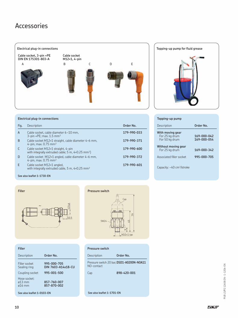
Filler
Description Order No.
Filler socket 995-000-705Sealing ring DIN 7603-A14x18-CU
Coupling socket 995-001-500
Hose socket: ø13 mm 857-760-007ø16 mm 857-870-002
Pressure switch
Description Order No.
Pressure switch 20 bar, NO-contact
DSD1-A0200N-NOA11
Cap 898-420-001
B C D E
Electrical plug-in connections
Fig. Description Order No.
A Cable socket, cable diameter 6–10 mm, 3-pin +PE; max. 1.5 mm²
179-990-033
B Cable socket M12×1 straight, cable diameter 4–6 mm, 4-pin, max. 0.75 mm²
179-990-371
C Cable socket M12×1 straight, 4-pin with integrally extruded cable; 5 m, 4×0.25 mm²)
179-990-600
D Cable socket M12×1 angled, cable diameter 4–6 mm, 4-pin, max. 0.75 mm²
179-990-372
E Cable socket M12×1 angled, with integrally extruded cable, 5 m, 4×0.25 mm²
179-990-601
See also leaflet 1-1730-EN
A
Electrical plug-in connections
Cable socket, 3-pin +PE Cable socket DIN EN 175301-803-A M12×1, 4-pin
Topping-up pump
Description Order No.
With moving gearFor 25 kg drum 169-000-042For 50 kg drum 169-000-054
Without moving gearFor 25 kg drum 169-000-342
Associated filler socket 995-000-705
Capacity: ~40 cm³/stroke
Topping-up pump for fluid grease
See also leaflet 1-1701-ENSee also leaflet 1-0103-EN
G1/4
A
10.5
Filler
SW24
M10×1 tap
Cap
459
79
Pressure switch
10

PUB LS/P2 12658 EN · 1-1206-EN
6
71
32
4
5
8
96
7
Main line connections
Item Description Order No.
1 Reinforcing socket, tube ø6 406-603Reinforcing socket, tube ø8 408-603Reinforcing socket, tube ø10 410-603
2 Socket union, tube ø6 406-612Socket union, tube ø8 408-612Socket union, tube ø10 410-612
3 Tapered sleeve, tube ø6 406-611Tapered sleeve, tube ø8 408-611Tapered sleeve, tube ø10 410-611
4 Socket union, tube ø6 406-002Socket union, tube ø8 408-202Socket union, tube ø10 410-002
5 Double tapered ring, tube ø6 406-001Double tapered ring, tube ø8 408-001Double tapered ring, tube ø10 410-001
6 Sealing ring DIN7603-A14×18-CU
7 Adapter, tube ø6 301-005Adapter, tube ø8 301-001Adapter, tube ø10 410-164
8 Push-to-connect fitting, tube ø6, straight 406-004-VS
9 Push-to-connect fitting, tube ø6, pivoted 506-140-VS
See also leaflet 1-0103-EN
Figure 7
For plastic tubing
For steel tubing
For plastic and steel tubing
Accessories
Main line connections
11
SKF Lubrication Systems Germany GmbH
Plant Berlin
Motzener Str. 35/37 · 12277 Berlin
PO Box 970444 · 12704 Berlin
Germany
Tel. +49 (0)30 72002-0
Fax +49 (0)30 72002-111
This brochure was presented to you by:
® SKF is a registered trademark of the SKF Group.
© SKF Group 2014The contents of this publication are the copyright of the publisher and may not be reproduced (even extracts) unless prior written permis-sion is granted. Every care has been taken to ensure the accuracy of the information contained in this publication. However, no liability can be accepted for any loss or damage whether direct, indirect or consequential, arising out of use of the information contained herein.
PUB LS/P2 12658 EN • July 2014 • 1-1206-EN
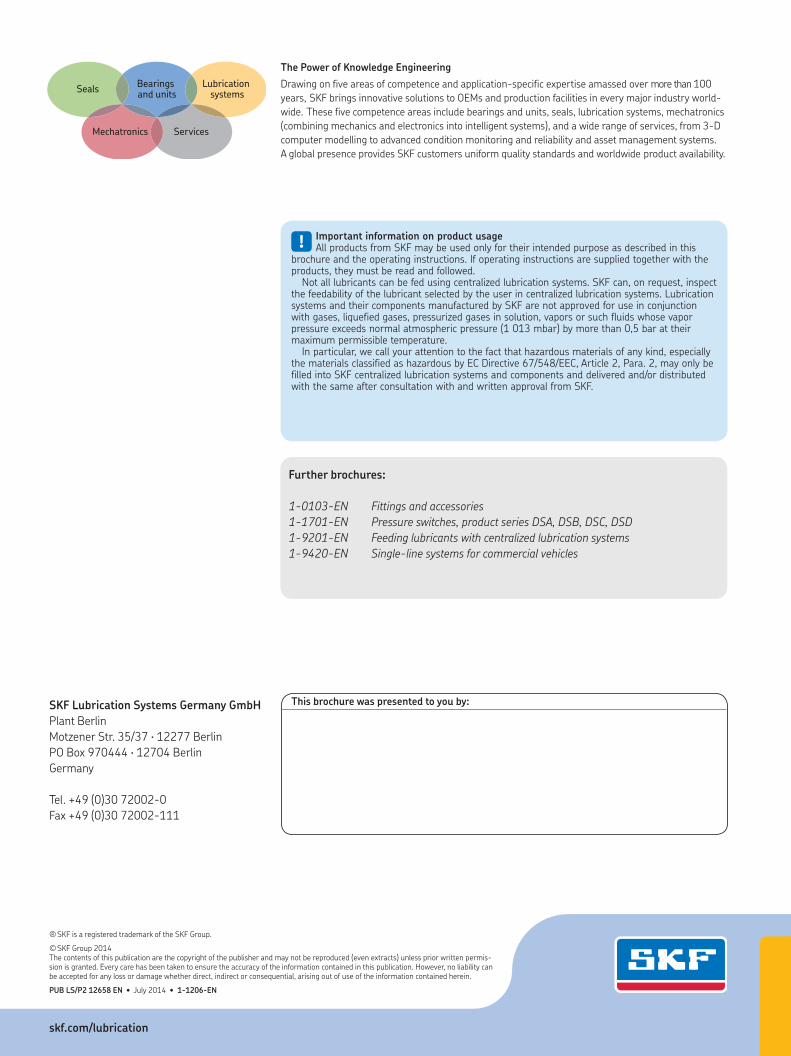
Bearings and units
SealsLubrication
systems
Mechatronics Services
The Power of Knowledge Engineering
Drawing on five areas of competence and application-specific expertise amassed over more than 100
years, SKF brings innovative solutions to OEMs and production facilities in every major industry world-
wide. These five competence areas include bearings and units, seals, lubrication systems, mechatronics
(combining mechanics and electronics into intelligent systems), and a wide range of services, from 3-D
computer modelling to advanced condition monitoring and reliability and asset management systems.
A global presence provides SKF customers uniform quality standards and worldwide product availability.
!Important information on product usageAll products from SKF may be used only for their intended purpose as described in this
brochure and the operating instructions. If operating instructions are supplied together with the products, they must be read and followed.
Not all lubricants can be fed using centralized lubrication systems. SKF can, on request, inspect the feedability of the lubricant selected by the user in centralized lubrication systems. Lubrication systems and their components manufactured by SKF are not approved for use in conjunction with gases, liquefied gases, pressurized gases in solution, vapors or such fluids whose vapor pressure exceeds normal atmospheric pressure (1 013 mbar) by more than 0,5 bar at their maximum permissible temperature.
In particular, we call your attention to the fact that hazardous materials of any kind, especially the materials classified as hazardous by EC Directive 67/548/EEC, Article 2, Para. 2, may only be filled into SKF centralized lubrication systems and components and delivered and/or distributed with the same after consultation with and written approval from SKF.
Further brochures:
1-0103-EN Fittings and accessories
1-1701-EN Pressure switches, product series DSA, DSB, DSC, DSD
1-9201-EN Feeding lubricants with centralized lubrication systems
1-9420-EN Single-line systems for commercial vehicles
skf.com/lubrication