
GEAR DESIGN SOLUTIONS - Dontyne · PDF fileof the Optimal calculation would ... gaudlitz gmbh...
20
GEAR DESIGN SOLUTIONS RELEASE 5.0 2013
Transcript of GEAR DESIGN SOLUTIONS - Dontyne · PDF fileof the Optimal calculation would ... gaudlitz gmbh...

GEAR DESIGN SOLUTIONS
Release 5.0 2013

the gear production Suite has been developed as a collection of individually licensed software tools (or modules). these can be applied at various points of the production process, and interface with existing software and equipment. this allows centralisation and analysis of
project data, leading to improved efficiency, cost savings and better quality control.
We also offer training for all our products, bespoke teaching courses and consultancy services for project work. We have completed
development programs with various partners for applications ranging from ship building, wind turbines and mining, to small scale and specialist equipment.
over 100 active installations in 15 countries
Dontyne Systems offers software and services aimed at the optimum production of gear components and their use in the transmission industry. our range of products allows end-to-end control of the gear manufacturing process by providing a common platform for design, machining and inspection software.
Dontyne SyStemS

Dontyne Offices HQ,
Newcastle, England
“Dontyne’s software brought us a huge improvement in productivity: reducing hours of work to seconds. The visual representations make the software very intuitive to use and understand, and the results are quite accurate. The endeavour was so successful that more collaboration is inevitable.”
eaton corporation
“The gear metrology expertise from Dontyne and the applications experience of Renishaw was an ideal combination to produce software that offers a high level of functionality and exploits the benefits of Renishaw’s co-ordinate measuring machine (CMM) scanning systems.”
renishaw plc
“The lead times and accuracy made possible by the introduction of the Optimal calculation would simply not have been possible without the software.”
gaudlitz gmbh
gearbox SyStem moDeL
gear DeSign
anaLySiS anD optimization
SoftWare tooLS
training anD Support
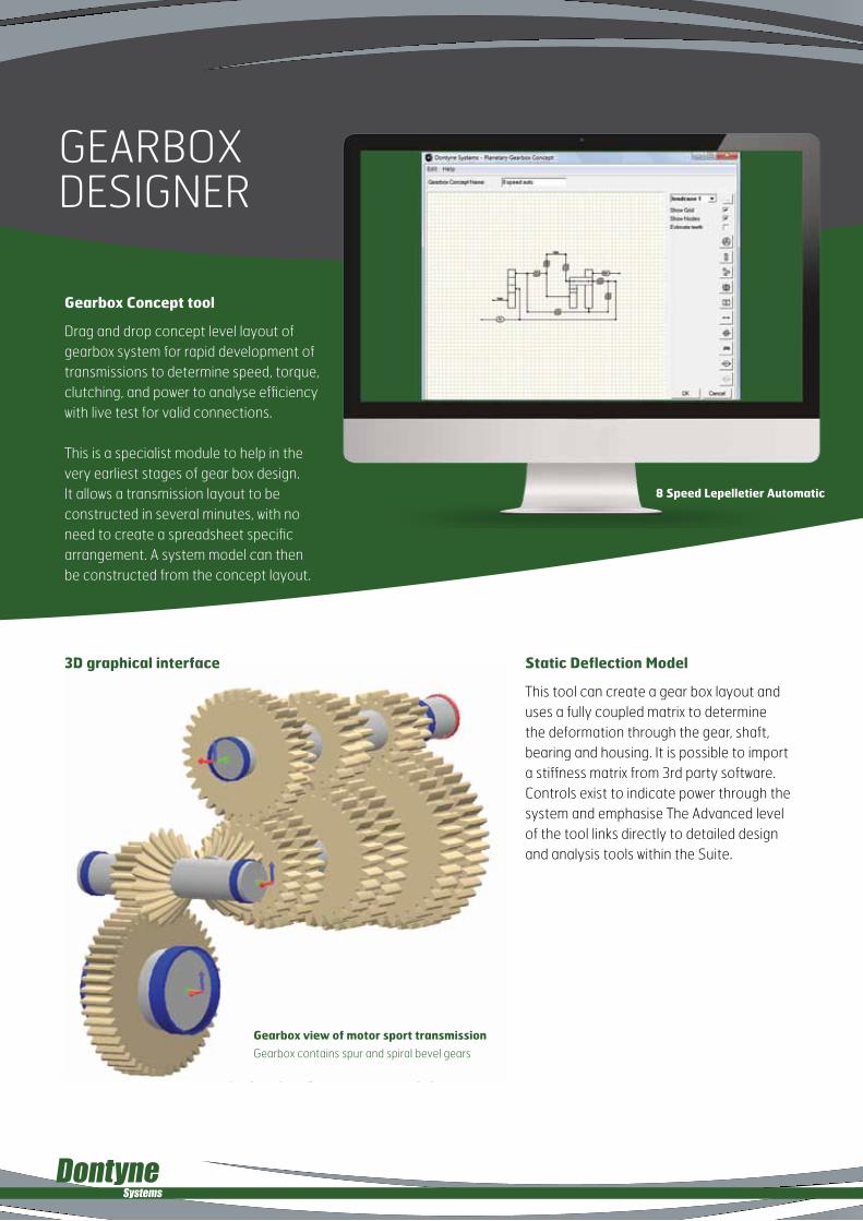
gearbox DeSigner
Gearbox Concept tool
Drag and drop concept level layout of gearbox system for rapid development of transmissions to determine speed, torque, clutching, and power to analyse efficiency with live test for valid connections.
this is a specialist module to help in the very earliest stages of gear box design. it allows a transmission layout to be constructed in several minutes, with no need to create a spreadsheet specific arrangement. a system model can then be constructed from the concept layout.
static Deflection Model
this tool can create a gear box layout and uses a fully coupled matrix to determine the deformation through the gear, shaft, bearing and housing. it is possible to import a stiffness matrix from 3rd party software. controls exist to indicate power through the system and emphasise the advanced level of the tool links directly to detailed design and analysis tools within the Suite.
8 speed lepelletier automatic
3D graphical interface
Gearbox view of motor sport transmission
gearbox contains spur and spiral bevel gears

8 speed lepelletier automatic
standard Features include :-
spur, Helical and Bevel gears
shaft Deflections
Misalignments in line of action
Forces
shaft stresses
Fully Coupled Housing stiffness Matrix
3D Gearbox Graphics
Deflected Plots
Concept or Detailed Gears
shaft assembly Designer
the shaft sections, gear positions and supports are input
shaft calculations for gear misalignment
Power flow plot

pLanetary DriVe DeSign
Features include :-
Involute spur and helical gear geometryassembly check for equal spacingsingle or double planet arrangementInterference checks for outer diametersspeed and torque of all componentsIsO 6336 rating (inc. 2008 updates)Tolerances to IsO 1328Cumulative damage and safety factor standardized tooth proportions or calculate for maximum contact ratioPlots of gears in 2D and 3DDXF output of transverse tooth profileCo-ordinates output of tooth profileMeasurement over balls and chordal pan including contact heightMetric or Imperial(english) unitsMaterial database (user defined)Phasing calculation
export DXF of tooth form
3D display of designs
single stage layout

gear DeSign anD rating
Features include :-
Involute internal and external spur and helical gear geometryIsO 6336 rating (inc. 2008 updates)aGMa 2001 – D 04 ratingTolerances to IsO 1328Tolerances to aGMa 2015standardized tooth proportions or calculate for maximum contact ratioPlots of gears in 2D and 3DDXF output of transverse tooth profileCo-ordinates output of tooth profileMeasurement over balls and chordal span including contact heightMetric or Imperial(english) unitsGear sizingFlash temperature calculations Graphical plot of specific slidingPlot of theoretical path of contactMaterial database (user defined)sN fatigue curve plots
Rating
Inspection
Design
Bevel Geometry

connectionS
Features include :-
IsO 4156 splinesDIN 5480 splinesaNsI B92.1 1970 splinesCalculation of load distribution in the bearingConsideration of centrifugal forces for high speed ball bearingssubsurface stresses for large bearings with surface hardening Calculation for bearing sets like multiple angular contact bearingsload spectraextension of contact ellipsis and contact angle under load Calculation with elastic outer ring for track rollersFull integration of bearing analysis including non-linear bearing stiffness in shaft toolCalculation of natural frequencies with gyroscopic effectCombined calculation of multiple coupled coaxial shaftsaxial and shear deformations are taken into account
Detailed design of connecting elements - splines.
splines
produce spline designs to iSo 4156, Din 5480 and anSi b92.1 1970 with an anSi rating system. the side, inner and outer variants are considered. the root rounding can be arbitrarily adjusted to user preference. all profiles can be exported as Dxf to wire erosion machines.

Shaft anD bearingS
Rolling bearing calculation according IsO/Ts 16281
the bearing life calculation according iSo/tS 16281 (2008) is the latest standardized version of a bearing life calculation. the bearing life is calculated using the load distribution on each rolling element and is therefore not limited to an external force but can also consider tilting moments and the influence of clearance or pretension. for each of the five degrees of freedom either a load or a displacement/rotation can be specified.
as in the calculation according iSo 281 (2007) the influence of the lubricant can be considered. either the ratio or the specific film thickness can be used. the life with and without consideration of the lubricant will be provided as result.
MesYs shaft Calculation
the shaft calculation allows the calculation of displacements, forces, strength according Din 743 and bearing life for several connected coaxial shafts. the meSyS rolling
bearing calculation according iSo/tS 16281 is included in the software and the nonlinear stiffness of rolling bearings in considered.
because of the nonlinear bearing stiffness shafts with more than two bearings can be calculated with accurate bearing forces as result. pretension of bearings can be considered. combinations of angular contact bearings can be easily considered as bearing set:
Rolling Bearing Calculation software

the load analysis program calculates the deformation of gear tooth components and their consequences on properties such as stress and transmission error (accuracy of ratio) under load. Versatile graphics and reporting features offer a quick interpretation of the resulting analysis and formatting
for customer reports. Links to metrology and manufacturing equipment enable evaluation of existing gear components as well as newly designed components. the advanced level of this module incorporates the fe calculation gateS originally developed and experimentally validated at the
Design unit, newcastle-upon-tyne, england. already implemented by some of the most trusted gear design and manufacturing institutions in the uK, the program has been used in the development of an extensive range of marine, industrial and automotive applications.
GaTes , Gear analysis for Transmission error and stress
Features include :-
surface definition, (profile and flank line modification)Contact stressRoot bending stress3D Fe model of tooth stiffnessPower loss and efficiencysurface topological modification definitionMultiple load casesDouble helical gearseffect of gear misalignmentVarious graphical interfacesImport of measured gear surface
aDVanceD LoaD anaLySiS moDeL
Gear contact stress Bearing load pattern Power loss and efficiency
specific film thickness calculation and IsO
TR- 15144 micro-pitting method a

Surface modification can be applied to minimise transmissions error (and hence noise and vibration effects) at a specific load
surface modifications defined by :-
Normal pressure angle change linear / parabolic profile modification4th degree polynomialsimulated biasa user model exported to GPs formatMeasured data compatible to common manufacturing systems
Nominal 3D surface modification / 3D surface with simulated or measured bias
Micro-geometry definition

aDVanceD LoaD anaLySiS moDeLmicropitting
Analysis of the Modified FZG ‘C’ type gears
the modified ‘c’ type gears were re-designed standard fzg gears with a 0.038 mm tip relief, starting just above the highest point of single tooth contact. the amount of tip relief was chosen such that under a torque level of LS10, premature engagement was just avoided.
to date, many different spur and helical gear sets have been analysed (from physical tests and field failures), with good correlation to the calculation procedures.
ls 5 to ls 10 and endurance
standard FZG Test Gear.
Modified FZG at end of load stage 10 – actual / Predicted.
ls 5 to ls 10 and endurance
Modified FZG Test Gear.
Dontyne Systems has been working with Dave barnett of gears made easy to introduce a method for predicting micropitting over extended periods of time, analysing its effects on performance and if it will arrest. this empirically derived analysis has been corroborated against actual gear tests and it can be concluded that micropitting is primarily dependent on the following factors:
1. Contact stress
2. Sliding velocity
3. Oil film thickness
4. Oil temperature
5. Slide roll ratio (SRR)
6. Surface finish (the RMS parameter ‘Ra’ is used in the calculations at present, but this may require modification)
7. Surface hardness
8. Number of contact cycles
9. Direction of sliding and the time that each surface is in contact with the corresponding gear in the pair.
10. Oil additive (Based on FZG micro-pitting oil test or based on actual gears)

microeroSion
Conclusion
- Comprehensive micro-pitting model originally developed by Dave Barnett based on results of a British Gear association research program.
- long term effects calculated beyond IsO limits including possible arrest of surface degradation
- Profile changes linked to TCa
- experimental validation (see aGMa paper 06FTM06)
- exclusive to Dontyne systems
The wear due to progressive mircopitting can be viewed in 3D at any stage.
Profile change at each stage added to Tooth Contact Model to show change in performance over time.
Te 0.85 after 10 hours
0.58 after 90 hours

aDVanceD LoaD anaLySiS moDeLconVoLoiD® tooth contact anaLySiS
Reduced stress enables more power
low tooth numbers and optimized root forms (no undercut)
Increase life potential
Reduced weight
Reduced centre distance
Carrier Comparison between existing 750KW Gearbox and Convoloid Enhanced Gearbox
Parameter existing 750KW
Planet Speed
Planet Torque
Bearing Type
Bearing Configuration
Bearing Loads
Bearing L10 life
Planet Carrier Weight
Planet/Brg Assembly
Ring
existing 750KW Gearbox
34.12 rpm
34.9 kN-M
Spherical Roller (2)
Under Planet
367.2 kN
129,900 hr
775 kg
225 kg
503 kg
Convoloid enhanced Gearbox
34.12 rpm
34.9 kN-m
Cylindrical Roller (4)
Straddle Mount
360.9 kN
124,900 hr
646 kg (-16.7%)
218 kg (-3.1%)
456 kg (-9.3%)
Improvement over involute for same ratio and face width
With projected cost savings at €24,431/MW
annual Production Projected Total savings
2,000MW €48,862,000
4,000MW €97,724,000
8,000MW €195,448,000
10,000MW €244,310,000
®
Dontyne Systems has completed several projects to develop customer specific applications or integrate functionality into the gear production Suite under licence.
one example is an exclusive agreement on convoloid gearing from genesis partners (uS).
Based on data from “20% Wind energy by 2030”, Us Department of energy

anaLySiS of inVoLute/conVoLoiD parameterS
Optimized Involute and Convoloid designs including tip relief
Improved Convoloid Centre relief
analysis used to establish envelope of operation where advantage is maintained.
analysis shows typical 10-30% reduction in stress and improved loading condition.
Relief applied to the transition zone to improve contact conditions further.
Centre distance tolerance
-0.075 mm
+0.075 mm

Features include :-
Tool designTool databasesimulation of profile generation and micro geometryanalysis of max/min tolerances on generated profileProtuberance and short lead hobbing techniques on profileUse tool generated profile in bending stress calculation for accurate rating
gear manufactureTool Design
Tool Database
search and select tool
Define new tool
Gear hobbing generated
profile to check tool design

Features include :-
Calculate resulting gear profile using existing tooling and machine settingsModel various machines and processes (Hob, Grind, Dress, shape, shave, Wire erosion, Injection Mould, Forge)Import/export of co-ordinate files to machine toolsImproved gear qualityReduced costs and resources shorter lead timesMore efficient production
Machine simulations
Thread grindingDressing and grinding
Balancing contact forces
for shaving
Cavity (Injection Moulding) Profile error calculated from existing tooling
Creating 3D models
for formed gears
produced by injection
moulding or forging

gear inSpection
Features include :-
Interfacing to gear measuring machines and co-ordinate measuring machines evaluation of linear errors Profile/flank/pitch to common standards (IsO, DIN, aGMa)2D scan for full form inspection in root 3D surface inspection simulation of physical inspection(measurement over balls, tooth span)simulation of contact testingstatistical analysis of productionDefinition of master surfaceDiagnostics and optimization of tool and machining process by compensation of errors
Co-ordinate evaluation Direct from Gear Inspection and CMM equipment
standard parameter evaluation
Virtual testing – tooth span, measurement over balls, transmission error

optimaLThis module uses measurements to improve tool or machine process accuracy.
Distorted gear due to shrinkage Invert errors on mould Improved quality gear
advanced analysis Functions
statistical evaluation of multiple measurements and creating a master surface
simulating dynamic tests such as contact marking with virtual master or other measured component

Dontyne SyStemS LimiteD iS a company regiStereD in engLanD anD WaLeS With company number 05973058regiStereD office: rotterDam houSe, 116 quaySiDe, neWcaStLe upon tyne ne1 3DyVat regiStration number: 902 9027 45
UKemaiL : [email protected] : +44 191 206 4021
gearbox SyStem moDeL
gear DeSign
anaLySiS anD optimization
SoftWare tooLS
training anD Support
www.dontynesystems.com