GE Diff Relay
18
A New Approach to Current Differential Protection for Transmission Lines GER-3981
-
Upload
sandy02477 -
Category
Documents
-
view
241 -
download
0
Transcript of GE Diff Relay

8/3/2019 GE Diff Relay
http://slidepdf.com/reader/full/ge-diff-relay 1/18
A New Approach to Current Differential
Protection for Transmission Lines
GER-3981
8/3/2019 GE Diff Relay
http://slidepdf.com/reader/full/ge-diff-relay 2/18
A New Approach to Current Differential
Protection for Transmission Lines
M. G. Adamiak Dr. W. Premerlani
G. E. Alexander GE Corporate
GE Power Management Research and DevelopmentMalvern, PA Schenectady, NY
Updated and Presented By
Subhash C. Patel
GE Power Management
Malvern, PA
Presented at the
ELECTRIC COUNCIL OF NEW ENGLAND
Protective Relaying Committee Meeting
October 22-23, 1998
Portsmouth, NH
8/3/2019 GE Diff Relay
http://slidepdf.com/reader/full/ge-diff-relay 3/18
1
A New Approach to Current Differential
Protection for Transmission Lines
M. G. Adamiak W. Premerlani
G. E. Alexander GE Corporate
GE Power Management Research and Development
Malvern, PA Schenectady, NY
(Updated by Subhash C. Patel, GE Power Management, Malvern, PA)
INTRODUCTION
This paper discusses a unique new approach to numerical current differential line protection that
offers improved performance over the conventional percentage restraint approach. The current
differential algorithm employs a new method of Fourier calculation that allows the protective
system to use “partial” Fourier signals called “phaselets” rather than the normal fixed window
Fourier approach. The phaselet approach also facilitates in the calculation of a confidence level
for the measured currents. This permits the current differential system to adapt its operating
characteristics based on the quality of the measured current values.
New adaptive approaches to pilot communications among the line terminals are also discussed.
These new approaches permit the current differential system to dynamically adjust for changes in
the transmission times between terminals, to account for different transmission times in each di-
rection, and to provide redundancy in the case of partial loss of communications.
Finally, the paper discusses the design of the message used to transfer the data among the line
terminals, the modulation techniques, and the physical interfaces to the communications media.
BASIC CURRENT DIFFERENTIAL RELAYING
Current differential relaying is applied to protect many elements of a power system. The simplest
example of a current differential relaying scheme is shown in Figure 1. The protected element
might be a length of circuit conductor, a generator winding, a bus section, etc. From Figure 1 it
can be seen that current differential relaying is a basic application of Kirchhoff’s Current Law.
The relay operates on the sum of the currents flowing in the CT secondaries, I1 + I2. For through

8/3/2019 GE Diff Relay
http://slidepdf.com/reader/full/ge-diff-relay 4/18
2
current conditions, such as load or an external fault, the currents in the two CT’s will be equal in
magnitude and opposite in phase (assuming the CT’s have the same ratio and are properly con-
nected), and there will be no current flow in the relay operate coil [1].
Figure 1
Should a short circuit occur within the protected section between the two CT’s, current will flow
through the operate circuit causing the relay to issue a trip output.
To improve the selectivity and security of the current differential scheme, it is often designed as a
percentage restraint differential relay. In a percentage restraint current differential relay, the oper-
ating current is the vector sum of the CT currents.
Ioperate = | I1 + I2 |
This operating current must be greater than some percentage (K1) of the restraint quantity which
is derived from the sum of the magnitude of the individual CT currents. A typical restraint current
could be:
Irestraint = k*[ | I1 | + | I2 | ]
The operating characteristic of the percentage restraint current differential relay with a slope of
K1 is shown in Figure 2.
Figure 2
PROTECTEDELEMENT
I1 I2
Iop=I1+I2
k*[ | I1 | + | I2 | ]
| I 1 + I 2 |
O P E R A T E
RESTRAINT
IMIN
K1

8/3/2019 GE Diff Relay
http://slidepdf.com/reader/full/ge-diff-relay 5/18
3
When a current differential relay is applied as unit protection within a station, for example on a
transformer, or a generator, the current from all of the CTs can be run directly to the relay. How-
ever, when current differential relaying is applied to a transmission line, the CTs are physically
separated, and it is not practical to connect the CT secondaries to the same relay. Therefore, in
transmission line applications, a pilot communications channel is used to transfer current data
between the substations. In such implementations, the pilot communications becomes an integralpart of the protective relay
PHASELETS AND VARIABLE WINDOW FOURIER TRANSFORM
When a transmission line current differential relay is implemented in a digital design, there are two
primary areas of concern. The first is the development of the current differential algorithm; the
second is in the design of the data communications algorithm. The differential current may be de-
veloped from the sampled current values, or the sampled values may be processed by a digital fil-
ter such as the Discrete Fourier Transform. Use of sample data only, while dependable, decreasesthe security of the protection as bad or missing samples may result in a misoperation. The Fourier
Transform, in conjunction with the confidence calculation discussed later, smoothes the data and
can provide dynamic restraint for bad or missing samples.
The traditional approach to the calculation of the Fourier employs a “sliding data window” (typi-
cally a half or full cycle). When a fault occurs, the sliding data window includes pre-fault data
along with fault data. Subsequently, the phasor estimation, (and the protective functions ) will
have an inherent transient time delay that is a function of the window size, as discussed in [2]. A
traditional Fourier Transform using a sliding one cycle data window is shown in Figure 3A. With
this approach, the magnitude of the output from the Fourier Transform does not equal the mag-
nitude of the sampled waveform until the Fourier window includes a full cycle of fault data, as
shown in Figure 3B.
-6
-5
-4
-3
-2
-1
0
1
2
3
4
5
6
0 32 64 96 128
Window 1
Window 2
Window 3
A. Fourier Windows B. Magnitude Response
Figure 3 - Traditional One Cycle Fourier Window
-6
-5
-4
-3
-2
-1
0
1
2
3
4
5
6
0 32 64 96 128
Window 1
Window 2Window 3

8/3/2019 GE Diff Relay
http://slidepdf.com/reader/full/ge-diff-relay 6/18
4
A previous paper [3], introduced the concept of phaselets and the variable window Fourier
transform as applied to distance type protection. The same approach may also be applied to a
digital current differential relay. The concept of a “variable window” has been developed to im-
prove the response of the phasor estimation, and as a direct result, to speed up the operating time
of the distance relay.
Phaselets are partial sums of the product of the waveform samples and the sine/cosine coeffi-
cients. Groups of phaselets may be added together and transformed to create a phasor. Phaselets
enable the efficient computation of phasors over sample windows that are not restricted to an in-
teger multiple of a half cycle at the power system frequency. In the case of a data window that is
a multiple of a half cycle, the computation is exactly equal to the Discrete Fourier Transform. In
the case of a window that is not a multiple of a half-cycle, there is an additional correction that
results from the sine and cosine functions not being orthogonal over such a window. However,
the correction computation can be expressed as a two by two matrix multiplication of the sine and
cosine weighted sums.
In steady state, non-fault, conditions, a one cycle window of data is used. The phaselets aresummed over one cycle, creating the equivalent of a one cycle window DFT. When a disturbance
is detected on the power system, the window size is dynamically reduced to the width of a single
phaselet which includes only fault data. As new phaselets are obtained, the window size is in-
creased to include the new data. Because all of the pre-fault data has been removed from the
window, the phasor estimate responds more quickly to the state of the power system. The accu-
racy of the estimate improves as each new phaselet is added. The data window continues to ex-
pand until it reaches a full cycle at which point the window reverts to a sliding window similar to
the conventional DFT. The variable Fourier window is depicted in Figure 4A.
The combination of the phaselets and the variable Fourier window allows the magnitude of the
Fourier output to estimate the magnitude of the sampled waveform in much less than one cycle(Figure 4B). This in turn produces faster operating times for the protective relays.
-6
-5
-4
-3
-2
-1
0
1
2
3
4
5
6
0 32 64 96 128
Window 1
Window 2
Window 3
A. Fourier Windows B. Magnitude Response
Figure 4 - Variable Width Fourier Window
-6
-5
-4
-3
-2
-1
0
1
2
3
4
5
6
0 32 64 96 128
Window 1
Window 2
Window 3
8/3/2019 GE Diff Relay
http://slidepdf.com/reader/full/ge-diff-relay 7/18
5
RESTRAINT CHARACTERISTIC
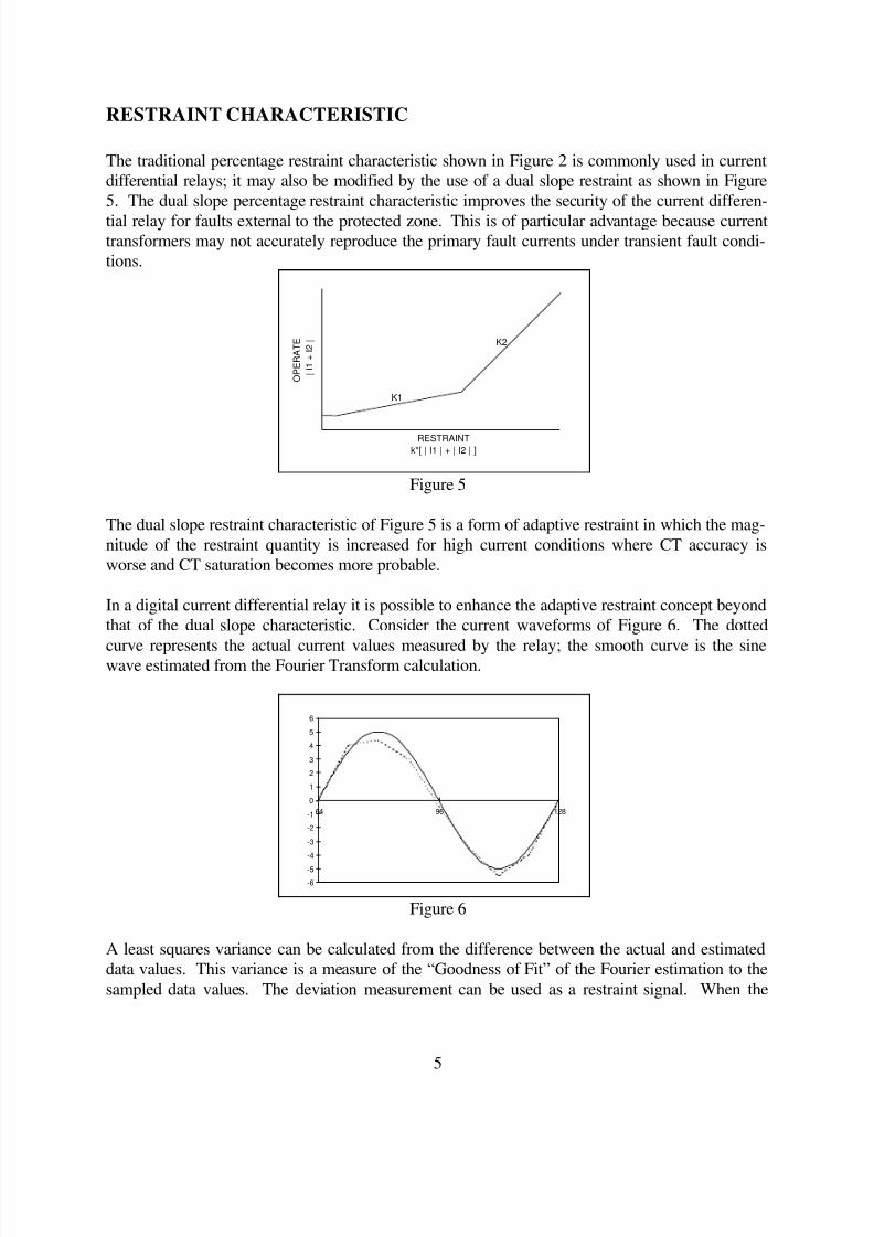
The traditional percentage restraint characteristic shown in Figure 2 is commonly used in current
differential relays; it may also be modified by the use of a dual slope restraint as shown in Figure
5. The dual slope percentage restraint characteristic improves the security of the current differen-
tial relay for faults external to the protected zone. This is of particular advantage because currenttransformers may not accurately reproduce the primary fault currents under transient fault condi-
tions.
Figure 5
The dual slope restraint characteristic of Figure 5 is a form of adaptive restraint in which the mag-
nitude of the restraint quantity is increased for high current conditions where CT accuracy is
worse and CT saturation becomes more probable.
In a digital current differential relay it is possible to enhance the adaptive restraint concept beyond
that of the dual slope characteristic. Consider the current waveforms of Figure 6. The dotted
curve represents the actual current values measured by the relay; the smooth curve is the sinewave estimated from the Fourier Transform calculation.
Figure 6
A least squares variance can be calculated from the difference between the actual and estimated
data values. This variance is a measure of the “Goodness of Fit” of the Fourier estimation to the
sampled data values. The deviation measurement can be used as a restraint signal. When the
k*[ | I1 | + | I2 | ]
| I 1 + I 2 |
O P E R A T E
RESTRAINT
K1
K2
-6
-5
-4
-3
-2
-1
0
1
2
3
4
5
6
64 96 128
8/3/2019 GE Diff Relay
http://slidepdf.com/reader/full/ge-diff-relay 8/18
6
waveform is distorted due to CT saturation, harmonic content, or fault initiation transients, the
restraint due to the “Goodness of Fit” calculation will increase.
The variance, σ, can be calculated for any size data window, W, by the formula:
σ
σ
= − • + •∑
=
=
=
=
= x X PL
x
X X
PL PL
i R Ri
W
i
R I
I I
2
1( )
,
X PL
Where: the "Goodness of Fit" error
the sample value at time i
, real & imaginary phasor components
real & imaginary phaslet components
I I
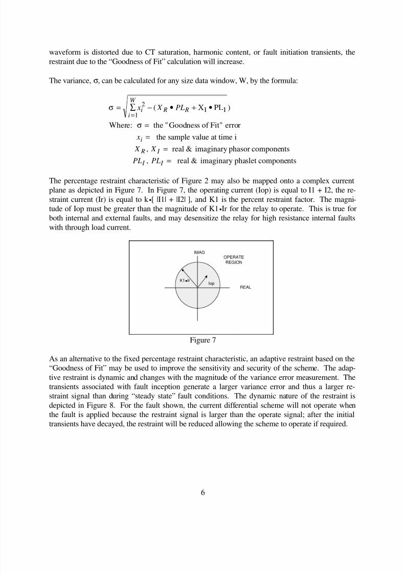
The percentage restraint characteristic of Figure 2 may also be mapped onto a complex current
plane as depicted in Figure 7. In Figure 7, the operating current (Iop) is equal to I1 + I2, the re-
straint current (Ir) is equal to k •[ |I1| + |I2| ], and K1 is the percent restraint factor. The magni-tude of Iop must be greater than the magnitude of K1•Ir for the relay to operate. This is true for
both internal and external faults, and may desensitize the relay for high resistance internal faults
with through load current.
Figure 7
As an alternative to the fixed percentage restraint characteristic, an adaptive restraint based on the
“Goodness of Fit” may be used to improve the sensitivity and security of the scheme. The adap-
tive restraint is dynamic and changes with the magnitude of the variance error measurement. The
transients associated with fault inception generate a larger variance error and thus a larger re-
straint signal than during “steady state” fault conditions. The dynamic nature of the restraint is
depicted in Figure 8. For the fault shown, the current differential scheme will not operate when
the fault is applied because the restraint signal is larger than the operate signal; after the initial
transients have decayed, the restraint will be reduced allowing the scheme to operate if required.
REAL
IMAG
K1lIrIop
OPERATE
REGION

8/3/2019 GE Diff Relay
http://slidepdf.com/reader/full/ge-diff-relay 9/18
7
Figure 8
The shape of the error variance restraint characteristic is dynamic and is based on the position of
the phaselet calculation as related to the point on wave of the fault inception. As such, the char-
acteristic can take on an elliptical shape based on whether the phase angle or magnitude is being
more accurately measured. As an example, if the waveform is sampled near a zero crossing, the
confidence in the phase angle measurement will be greater than the confidence in the magnitudeestimate. If the waveform is sampled near the peak of the current waveform, the confidence in
the magnitude estimate will be greater than the confidence the phase angle estimate. The orienta-
tion of the ellipse will rotate depending on the incidence angle of the sampling.
Figure 9
Improved coverage is possible with this scheme by reducing, or eliminating, the traditional per-
centage restraint setting. The improvement in the sensitivity of the protection is shown in Figure
9. In this condition, there is no loss of dependability as the restraint dynamically grows for ques-
tionable signals. It is also possible to combine the traditional percentage differential scheme with
the adaptive restraint approach. This will allow an improvement in both security and dependabil-ity determined by user settings.
REAL
IMAG
Iop
OPERATE
REGION
STEADY STATE
RESTRAINT
DYNAMIC
RESTRAINT
REAL
IMAG
Iop
OPERATE
REGION
DYNAMICELLIPTICAL
RESTRAINT
TRADITIONALCIRCULAR
RESTRAINT
STEADY STATE
CIRCULAR
RESTRAINT

8/3/2019 GE Diff Relay
http://slidepdf.com/reader/full/ge-diff-relay 10/18
8
The net operating quantity for the current differential relay employing the proposed signals is:
Operate = C + C - K C Restraint -C - K1
2
2
2
1 3
2
4 2• • • • • • • X X X X R I R I σ
2
Where:
The first two terms are analogous to the operate quantity of a conventional current differ-
ential relay.
The third term is analogous to the percentage restraint characteristic of a conventional
current differential relay.
The last term is a measure of the “Goodness of Fit”. Also the last two terms determine
the shape and orientation of the elliptical characteristic.
C1-C4 are covariance terms.
K1 and K2 are constants.
The net operate signal is effectively a measure of the distance from the operate signal to the re-
straint characteristic (balance point).
CLOCK SYNCHRONIZATION / PATH DELAY CORRECTION
One of the primary requirements of a current differential is that all the data used in the differential
calculation be related in time. As such, there is a need to set and maintain very accurate clocks
within the relay. There are two primary techniques that can be implemented to obtain this re-quirement. The first technique is to maintain a clock based on some external time source. The
most widely available source that could be used is absolute time as available from the Global Po-
sitioning Satellite (GPS) system. Time accuracy of better that 1 usec is available from GPS
clocks. Drawbacks with this technique are that additional hardware is required to implement the
timing function and the long term availability is not guaranteed with this system as its primary
function is military based.
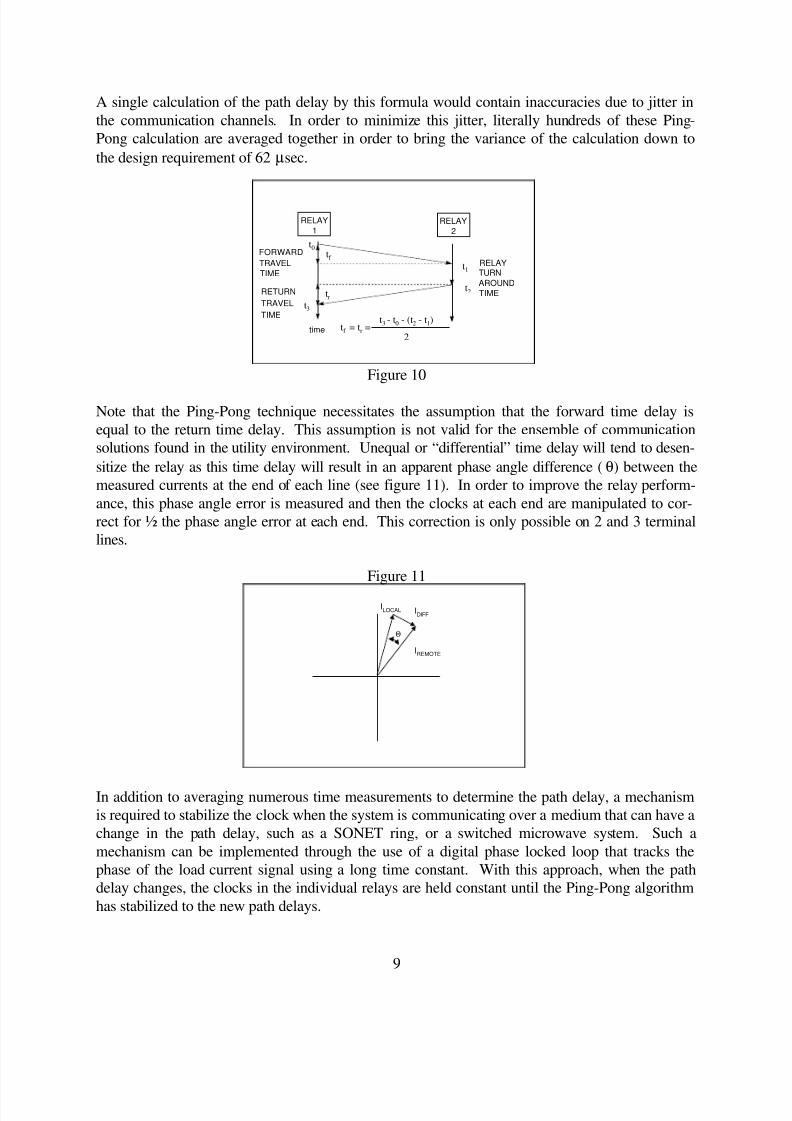
An alternative synchronization technique that requires no additional hardware is the Internet tech-
nique known as “Ping Pong” [4]. Ping Pong relies on measuring the forward and return message
communication times and using the measured time to properly correlate the received data with the
local data. The communication delay time calculation is illustrated in figure 10. In its basic op-
eration, relay 1 time tags and sends a message to relay 2 at time t0. Relay 2 receives the message
at time t1, sets it time to the received time, and returns the message to relay 1 at time t2. Relay 1
receives the message at time t3 and can now compute the assumed one way delay as:
tf = tr = (t3 - t0 - (t2 - t1)) / 2
8/3/2019 GE Diff Relay
http://slidepdf.com/reader/full/ge-diff-relay 11/18
9
A single calculation of the path delay by this formula would contain inaccuracies due to jitter in
the communication channels. In order to minimize this jitter, literally hundreds of these Ping-
Pong calculation are averaged together in order to bring the variance of the calculation down to
the design requirement of 62 µsec.
Figure 10
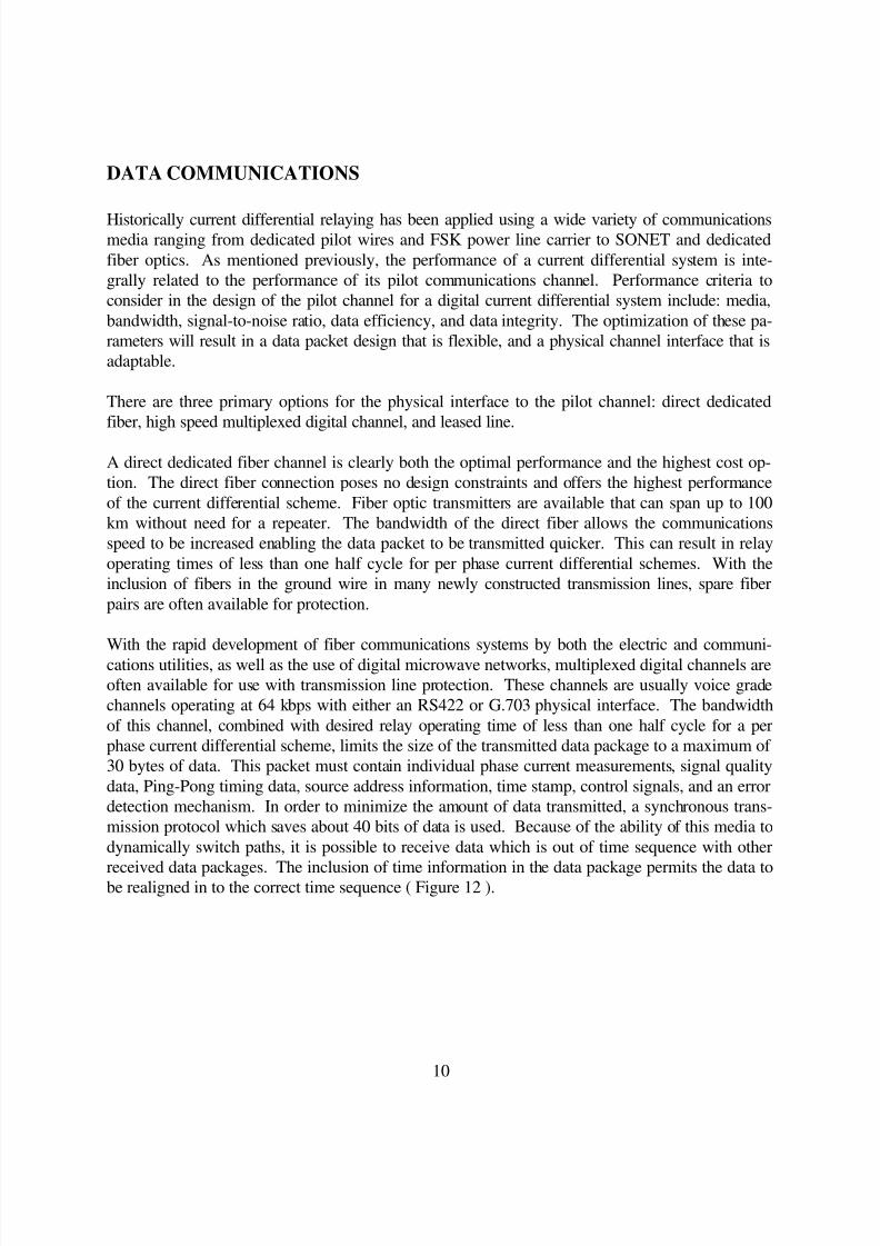
Note that the Ping-Pong technique necessitates the assumption that the forward time delay is
equal to the return time delay. This assumption is not valid for the ensemble of communication
solutions found in the utility environment. Unequal or “differential” time delay will tend to desen-
sitize the relay as this time delay will result in an apparent phase angle difference (θ) between the
measured currents at the end of each line (see figure 11). In order to improve the relay perform-
ance, this phase angle error is measured and then the clocks at each end are manipulated to cor-
rect for ½ the phase angle error at each end. This correction is only possible on 2 and 3 terminal
lines.
Figure 11
In addition to averaging numerous time measurements to determine the path delay, a mechanism
is required to stabilize the clock when the system is communicating over a medium that can have a
change in the path delay, such as a SONET ring, or a switched microwave system. Such a
mechanism can be implemented through the use of a digital phase locked loop that tracks the
phase of the load current signal using a long time constant. With this approach, when the path
delay changes, the clocks in the individual relays are held constant until the Ping-Pong algorithm
has stabilized to the new path delays.
RELAY
1
time
t0
t1
t2
t3
tf
tr
tf = tr =t3 - t0 - (t2 - t1)
2
RELAY
2
FORWARD
TRAVEL
TIME
RETURN
TRAVEL
TIME
RELAYTURN
AROUND
TIME
IDIFF
IREMOTE
ILOCAL
Θ
8/3/2019 GE Diff Relay
http://slidepdf.com/reader/full/ge-diff-relay 12/18
10
DATA COMMUNICATIONS
Historically current differential relaying has been applied using a wide variety of communicationsmedia ranging from dedicated pilot wires and FSK power line carrier to SONET and dedicated
fiber optics. As mentioned previously, the performance of a current differential system is inte-
grally related to the performance of its pilot communications channel. Performance criteria to
consider in the design of the pilot channel for a digital current differential system include: media,
bandwidth, signal-to-noise ratio, data efficiency, and data integrity. The optimization of these pa-
rameters will result in a data packet design that is flexible, and a physical channel interface that is
adaptable.
There are three primary options for the physical interface to the pilot channel: direct dedicated
fiber, high speed multiplexed digital channel, and leased line.
A direct dedicated fiber channel is clearly both the optimal performance and the highest cost op-
tion. The direct fiber connection poses no design constraints and offers the highest performance
of the current differential scheme. Fiber optic transmitters are available that can span up to 100
km without need for a repeater. The bandwidth of the direct fiber allows the communications
speed to be increased enabling the data packet to be transmitted quicker. This can result in relay
operating times of less than one half cycle for per phase current differential schemes. With the
inclusion of fibers in the ground wire in many newly constructed transmission lines, spare fiber
pairs are often available for protection.
With the rapid development of fiber communications systems by both the electric and communi-
cations utilities, as well as the use of digital microwave networks, multiplexed digital channels are
often available for use with transmission line protection. These channels are usually voice grade
channels operating at 64 kbps with either an RS422 or G.703 physical interface. The bandwidth
of this channel, combined with desired relay operating time of less than one half cycle for a per
phase current differential scheme, limits the size of the transmitted data package to a maximum of
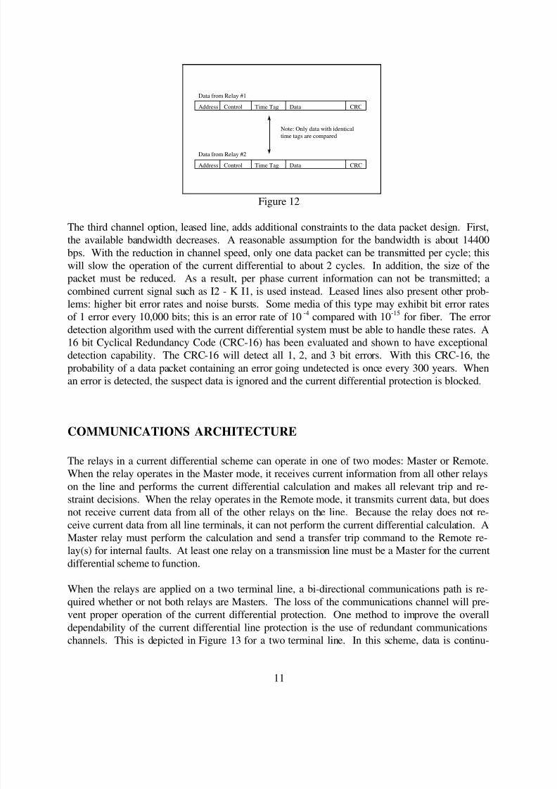
30 bytes of data. This packet must contain individual phase current measurements, signal quality
data, Ping-Pong timing data, source address information, time stamp, control signals, and an error
detection mechanism. In order to minimize the amount of data transmitted, a synchronous trans-
mission protocol which saves about 40 bits of data is used. Because of the ability of this media to
dynamically switch paths, it is possible to receive data which is out of time sequence with other
received data packages. The inclusion of time information in the data package permits the data tobe realigned in to the correct time sequence ( Figure 12 ).
8/3/2019 GE Diff Relay
http://slidepdf.com/reader/full/ge-diff-relay 13/18
11
Figure 12
The third channel option, leased line, adds additional constraints to the data packet design. First,
the available bandwidth decreases. A reasonable assumption for the bandwidth is about 14400
bps. With the reduction in channel speed, only one data packet can be transmitted per cycle; this
will slow the operation of the current differential to about 2 cycles. In addition, the size of the
packet must be reduced. As a result, per phase current information can not be transmitted; acombined current signal such as I2 - K I1, is used instead. Leased lines also present other prob-
lems: higher bit error rates and noise bursts. Some media of this type may exhibit bit error rates
of 1 error every 10,000 bits; this is an error rate of 10 -4 compared with 10-15 for fiber. The error
detection algorithm used with the current differential system must be able to handle these rates. A
16 bit Cyclical Redundancy Code (CRC-16) has been evaluated and shown to have exceptional
detection capability. The CRC-16 will detect all 1, 2, and 3 bit errors. With this CRC-16, the
probability of a data packet containing an error going undetected is once every 300 years. When
an error is detected, the suspect data is ignored and the current differential protection is blocked.
COMMUNICATIONS ARCHITECTURE
The relays in a current differential scheme can operate in one of two modes: Master or Remote.
When the relay operates in the Master mode, it receives current information from all other relays
on the line and performs the current differential calculation and makes all relevant trip and re-
straint decisions. When the relay operates in the Remote mode, it transmits current data, but does
not receive current data from all of the other relays on the line. Because the relay does not re-
ceive current data from all line terminals, it can not perform the current differential calculation. A
Master relay must perform the calculation and send a transfer trip command to the Remote re-
lay(s) for internal faults. At least one relay on a transmission line must be a Master for the currentdifferential scheme to function.
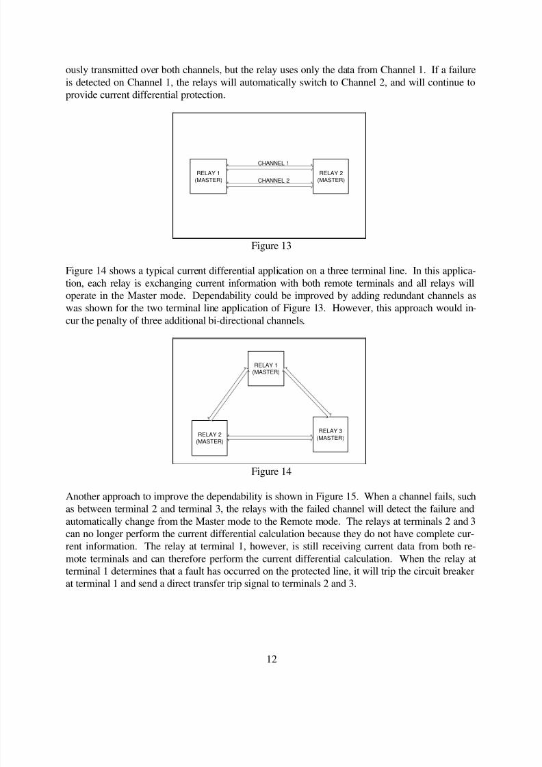
When the relays are applied on a two terminal line, a bi-directional communications path is re-
quired whether or not both relays are Masters. The loss of the communications channel will pre-
vent proper operation of the current differential protection. One method to improve the overall
dependability of the current differential line protection is the use of redundant communications
channels. This is depicted in Figure 13 for a two terminal line. In this scheme, data is continu-
Address Control Time Tag Data CRC
Data from Relay #1
Address Control Time Tag Data CRC
Data from Relay #2
Note: Only data with identical
time tags are compared
8/3/2019 GE Diff Relay
http://slidepdf.com/reader/full/ge-diff-relay 14/18
12
ously transmitted over both channels, but the relay uses only the data from Channel 1. If a failure
is detected on Channel 1, the relays will automatically switch to Channel 2, and will continue to
provide current differential protection.
Figure 13
Figure 14 shows a typical current differential application on a three terminal line. In this applica-tion, each relay is exchanging current information with both remote terminals and all relays will
operate in the Master mode. Dependability could be improved by adding redundant channels as
was shown for the two terminal line application of Figure 13. However, this approach would in-
cur the penalty of three additional bi-directional channels.
Figure 14
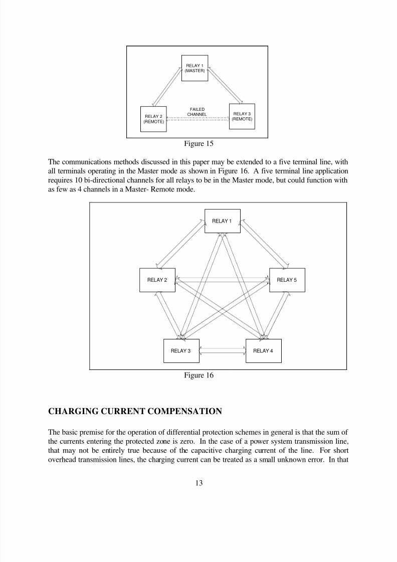
Another approach to improve the dependability is shown in Figure 15. When a channel fails, such
as between terminal 2 and terminal 3, the relays with the failed channel will detect the failure and
automatically change from the Master mode to the Remote mode. The relays at terminals 2 and 3
can no longer perform the current differential calculation because they do not have complete cur-rent information. The relay at terminal 1, however, is still receiving current data from both re-
mote terminals and can therefore perform the current differential calculation. When the relay at
terminal 1 determines that a fault has occurred on the protected line, it will trip the circuit breaker
at terminal 1 and send a direct transfer trip signal to terminals 2 and 3.
RELAY 1
(MASTER)
RELAY 2
(MASTER)
CHANNEL 1
CHANNEL 2
RELAY 1(MASTER)
RELAY 3
(MASTER)RELAY 2
(MASTER)
8/3/2019 GE Diff Relay
http://slidepdf.com/reader/full/ge-diff-relay 15/18
13
Figure 15
The communications methods discussed in this paper may be extended to a five terminal line, with
all terminals operating in the Master mode as shown in Figure 16. A five terminal line application
requires 10 bi-directional channels for all relays to be in the Master mode, but could function with
as few as 4 channels in a Master- Remote mode.
Figure 16
CHARGING CURRENT COMPENSATION
The basic premise for the operation of differential protection schemes in general is that the sum of
the currents entering the protected zone is zero. In the case of a power system transmission line,
that may not be entirely true because of the capacitive charging current of the line. For short
overhead transmission lines, the charging current can be treated as a small unknown error. In that
RELAY 1
(MASTER)
RELAY 3
(REMOTE)RELAY 2
(REMOTE)
FAILED
CHANNEL
RELAY 2 RELAY 5
RELAY 1
RELAY 3 RELAY 4
8/3/2019 GE Diff Relay
http://slidepdf.com/reader/full/ge-diff-relay 16/18
14
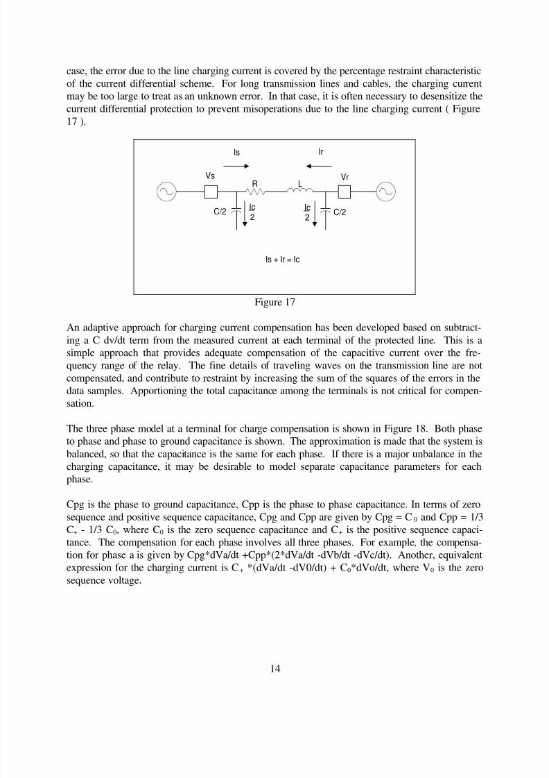
case, the error due to the line charging current is covered by the percentage restraint characteristic
of the current differential scheme. For long transmission lines and cables, the charging current
may be too large to treat as an unknown error. In that case, it is often necessary to desensitize the
current differential protection to prevent misoperations due to the line charging current ( Figure
17 ).
Is Ir
Vs VrR
C/2 C/2
L
Ic2
Ic2
Is + Ir = Ic
Figure 17
An adaptive approach for charging current compensation has been developed based on subtract-
ing a C dv/dt term from the measured current at each terminal of the protected line. This is a
simple approach that provides adequate compensation of the capacitive current over the fre-
quency range of the relay. The fine details of traveling waves on the transmission line are not
compensated, and contribute to restraint by increasing the sum of the squares of the errors in the
data samples. Apportioning the total capacitance among the terminals is not critical for compen-
sation.
The three phase model at a terminal for charge compensation is shown in Figure 18. Both phase
to phase and phase to ground capacitance is shown. The approximation is made that the system is
balanced, so that the capacitance is the same for each phase. If there is a major unbalance in the
charging capacitance, it may be desirable to model separate capacitance parameters for each
phase.
Cpg is the phase to ground capacitance, Cpp is the phase to phase capacitance. In terms of zero
sequence and positive sequence capacitance, Cpg and Cpp are given by Cpg = C0 and Cpp = 1/3
C+ - 1/3 C0, where C0 is the zero sequence capacitance and C+ is the positive sequence capaci-
tance. The compensation for each phase involves all three phases. For example, the compensa-tion for phase a is given by Cpg*dVa/dt +Cpp*(2*dVa/dt -dVb/dt -dVc/dt). Another, equivalent
expression for the charging current is C+ *(dVa/dt -dV0/dt) + C0*dVo/dt, where V0 is the zero
sequence voltage.

8/3/2019 GE Diff Relay
http://slidepdf.com/reader/full/ge-diff-relay 17/18
15
CppCpp
Cpp
Cpg
CpgCpg
Figure 18
The compensation scheme dynamically apportions the charge current correction based on line
configurations by noting terminal open/close status and voltage transformer location.
CONCLUSIONS
New techniques in the calculation of the Fourier transform in digital relays allow the relay to more
quickly estimate the fault currents; this is turn improves the operating time of the relays.
In a digital implementation, the traditional percentage restraint current differential characteristic
can be augmented, or replaced, with an adaptive restraint based on the variance between the sam-
pled data and the Fourier estimate of the data.
Channel path delay errors can be reduced by compensating for different path delays in each direc-
tion, and dynamic changes in the channel delay can be accommodated.
The reliability of the current differential scheme can be improved by reducing the dependency of
the scheme on the communications channel. This can be done by adding redundant channels, or
by adapting the relay operation to the available channels by automatically converting from a Mas-
ter to a Remote mode of operation.
8/3/2019 GE Diff Relay
http://slidepdf.com/reader/full/ge-diff-relay 18/18
16
REFERENCES
[1] C. R. Mason, The Art and Science of Protective Relaying. New York: John Wiley and
Sons, Inc., 605 Third Ave. NY, NY 10158 1956.
[2] J. M. Kennedy and G. E. Alexander, “ Variable Digital Filter Response Time in a Digital
Distance Relay”, Twentieth Annual Western Protective Relaying Conference, October
1993.
[3] M. G. Adamiak, G. E. Alexander, and W. Premerlani, “Advancements in Adaptive Algo-
rithms for Secure High Speed Distance Protection, ”, Twenty Third Annual Western Pro-
tective Relaying Conference, October 1996.
[4] D. L. Mills, “Internet Time Synchronization: The Network Time Protocol”, IEEE Transac-
tions on Communications, Vol. 39, No. 10, October 1991.