February, 2013 MicroStation V8i and InRoads V8i (SELECTseries 2

GEORGIA DEPARTMENT OF TRANSPORTATION
ROOT MENU FOR MICROSTATION V8i
Version 4.1.9
Current Revision Date:
April 2014

1-1 GDOT Root Menu
This document provides guidance for the usage of the GDOT Root Menu application that is included in the GDOT Workspace for MicroStation V8i.
Page 2 of 140

RootMenuforMicroStationV8i April 2014
1-2 TABLE OF CONTENTS
Section 1 - GDOT Root Menu for MicroStation V8i - Section 1 1-1 GDOT Root Menu for MicroStation V8i 1-2 Table of Contents 1-3 General Description 1-4 Rules of Operation Section 2 - GDOT Root Menu - Brief 2-1 GDOT Root Menu – Brief
2-2 Plan Sheets 2-3 Reference File Menus 2-4 Tools 2-5 Design Aids 2-6 Mapping 2-7 Help 2-8 Links
Section 3 - Plan Sheets Expanded 3-1 Plan Sheets – Expanded 3-2 GDOT DGN Reference Files/Plan Sheet Builder Application 3-3 01 – Cover Sheet 3-4 02 – Index Sheet 3-5 03 – Revision Summary Sheet 3-6 04 – General Notes 3-7 05 – Typical Sections 3-8 06 – Summary of Quantities 3-9 07 – Quantities by Amendment 3-10 08 – Quantities use on Construction 3-11 10 – Traffic Diagram Sheets 3-12 11 – Construction Layout 3-13 12 – Miscellaneous Maps 3-14 13 – Mainline Roadway Plan 3-15 14 – Crossroad Plan 3-16 15 – Mainline Roadway Profile
Page 3 of 140

RootMenuforMicroStationV8i April 2014
3-17 16 – Xroad Profiles 3-18 17 – Driveway Profiles 3-19 18 – Special Grading Sheets 3-20 19 – Staging Plan 3-21 20 – Staging Details 3-22 21 – Drainage Area Map 3-23 22 – Drainage Profiles 3-24 23 – Cross Sections 3-25 24 – Utility Plan 3-26 25 – Lighting Plans and Details 3-27 26 – Signing and Marking Plan 3-28 27 – Signal Plan 3-29 28 – ITS Plan 3-30 29 – Landscaping Plan 3-31 30 – Mitigation Plan 3-32 31 – Retaining Wall Envelopes 3-33 32 – Retaining Wall Plan 3-34 33 – Sound Barrier Envelopes 3-35 34 – Sound Barrier Plan 3-36 35 – Bridge Plans (To be released at a later date.) 3-37 36 – Bridge Culvert Plans (To be released at a later date.) 3-38 37 – Miscellaneous Structural (To be released at a later date.) 3-39 38 – Special Construction Details (To be released at a later date.) 3-40 39 – Special Design Box Culverts (To be released at a later date.) 3-41 40 – Construction Details 3-42 41 – Georgia Standards 3-43 44 – Utility Relocation Plans 3-44 50 – Erosion Cover Sheet 3-45 51 – ESPCP General Notes 3-46 52 – Erosion Control Legend (To be released at a later date.) 3-47 53 – ESPCP Drainage Area Map 3-48 54 – BMP Location Details (1), (2), (3), (4) and (5) 3-49 55 – EC Watershed Map-Site Monitoring 3-50 56 – Construction Standards & Details for Erosion Control ONLY 3-51 60 – Right of Way Plan – Cover 3-52 60 – Right of Way Plan – Sheets
Page 4 of 140
RootMenuforMicroStationV8i April 2014
Section 4 - Reference File Expanded 4-1 Reference Files – Expanded 4-2 Sheet Layout Tools 4-3 [MAIN] Alignment / Edge of Pavement 4-4 [DRNG] Drainage (Plan View) 4-5 [REQD] Required Right of Way & Easements 4-6 [SIGN] Signing and Pavement Marking 4-7 [SGNL] Signal Plans 4-8 [ITS] ITS Plans 4-9 [UTLE] Existing Utilities 4-10 [UTLP] Proposed Utilities 4-11 [LIMT] Construction Limits 4-12 [STE#] Staging and Erosion Control 4-13 [ENVE] Existing Environmental & Cultural Resources 4-14 [ENVP] Proposed Environmental & Cultural Resources 4-15 [LNSC] Landscaping 4-16 [LGHT] Lighting 4-17 [TYPS] Typical Sections 4-18 [CNCP-E] Existing Concept Items 4-19 [CNCP-P] Proposed Concept Items Section 5 - Tools Expanded 5-1 Tools Expanded
5-2 LevelWorks 5-3 GPlot PDF Plotting Section 6 - Miscellaneous Items 6-1 Miscellaneous Items 6-2 Other Sources of Information 6-3 Questions or Comments
Page 5 of 140

RootMenuforMicroStationV8i April 2014
1‐3 General Description
The GDOT Root Menu is designed to:
Lead users through MicroStation tasks with minimal training.
Automate MicroStation tasks.
Ensure that Department CAD Standards are followed.
Ensure plan consistency internally and externally.
The GDOT Root Menu can be accessed from inside MicroStation V8i when using the GDOT WorkSpace from the GDOT Tools menu located on the top MicroStation Main Menu Bar under GDOT ToolsGDOT_Menu as shown below.
Page 6 of 140

RootMenuforMicroStationV8i April 2014
1‐3 General Description (continued)
The GDOT Root Menu is divided into five sections divided by user selectable tabs across the top of the menu:
Plan Sheets o Creation of Plan Sheets divided into section numbers as documented in the
GDOT Plan Presentation Guide (PPG). o Setting of Plan Sheet levels as documented in the GDOT Electronic Data
Guidelines (EDG).
Reference File Menus o Specific to the separate reference files. o Tools organized by reference file logical names.
Tools o GPlot o LevelWorks o Various other tools that are not reference file specific.
Design Aids o AutoTURN o AutoTURN User Guide o TORUS o TORUS User Guide
Page 7 of 140

RootMenuforMicroStationV8i April 2014
1‐3 General Description (continued)
Mapping o TOPO to UTIL (to be released at a later date) o GridTic (to be released at a later date)
Help o GDOT Menu Tools Documentation o MicroStation KeyIn Commands o GPlot Documentation o Viewing DGNs in Google Earth o WMS Imagery Services
Links o PPG o EDG o Google o R.O.A.D.S.
Page 8 of 140

RootMenuforMicroStationV8i April 2014
1‐4 Rules of Operation
Most of the menus are designed with the buttons laid out four columns wide and four rows high.
Menus wider than four columns wide have a slide bar located at the bottom to allow the user to access additional tasks to the right of each menu.
All submenus are accessed through the Main Menu via one of the five menu tabs.
When a user selects and opens a submenu the GDOT Main Menu will close and the appropriate submenu will open. After the user selects the CLOSE button on a submenu the GDOT Main Menu will reopen automatically.
Page 9 of 140

RootMenuforMicroStationV8i April 2014
1‐4 Rules of Operation (continued)
Most Plan Sheet menus will lead the user to the next logical step by highlighting the most likely next task button after each step.
Most commands will have “Tool Tips” that display when the mouse cursor is held over a given button.
After a step has been completed the corresponding button will gray out to let the user know what tasks they have completed. In the event the user desires to re‐do a step they may click the “Reset” button to reactivate all the buttons on that step. The “Reset” button will only activate after the user has used one or more button commands.
Most menus that involve placing elements at multiple plan scales will automatically gray out the other scale options after the user selects the first item. In the example above the user has already placed a 50 Scale North Arrow, notice that the 20 Scale and 100 Scale options for the remaining tasks were turned off automatically.
Page 10 of 140

2-1 GDOT Root Menu – Brief
The following sections provide in a summarized format the functions each tab of the GDOT Root Menu that is included in the GDOT Workspace for MicroStation V8i.
Page 11 of 140

RootMenuforMicroStationV8i April 2014
2‐2 Plan Sheets Tab
Reference and Sheet File Builder – Verifies which reference files the user has previously
created and creates new “blank” design files with the correct names to allow the user to
proceed with building the plan sheets. These “blank” design files can later be populated
as the information for each is generated during the plans development process. In
addition this menu can build the “blank” plan sheet design files for the user.
01 – Cover Sheet – Used to build the Section 01 Construction Cover sheet.
02 – Index Sheet – Used to create the Section 02 Construction Plan Index sheet.
03 ‐ Revision Summary Sheet – Used to create the Section 03 Revision Summary Plan
sheet(s).
04 ‐ General Notes – Used to create the Section 04 General Notes Plan sheet(s).
05 ‐ Typical Sections – Used to create the Section 05 Typical Sections Plan sheet(s).
06 – Summary of Quantities – Used to create the Section 06 Summary of Quantities
Plan sheet(s).
Page 12 of 140
RootMenuforMicroStationV8i April 2014
2‐2 Plan Sheets Tab
(continued)
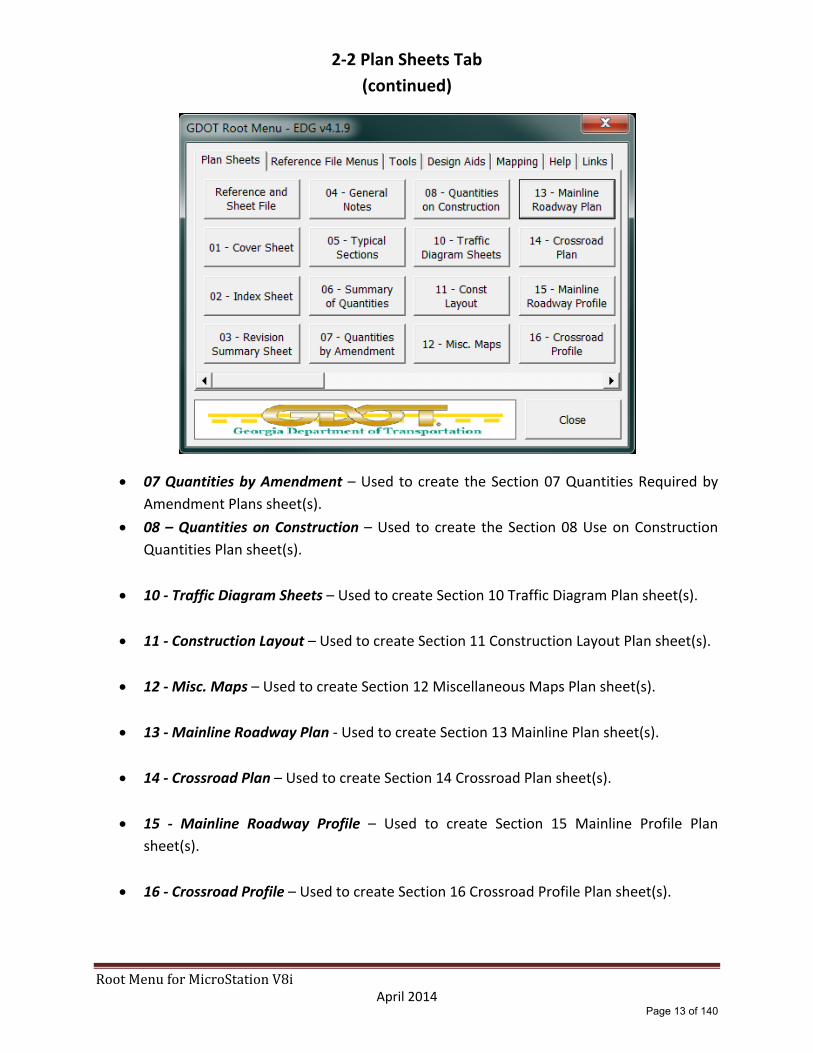
07 Quantities by Amendment – Used to create the Section 07 Quantities Required by
Amendment Plans sheet(s).
08 – Quantities on Construction – Used to create the Section 08 Use on Construction
Quantities Plan sheet(s).
10 ‐ Traffic Diagram Sheets – Used to create Section 10 Traffic Diagram Plan sheet(s).
11 ‐ Construction Layout – Used to create Section 11 Construction Layout Plan sheet(s).
12 ‐ Misc. Maps – Used to create Section 12 Miscellaneous Maps Plan sheet(s).
13 ‐ Mainline Roadway Plan ‐ Used to create Section 13 Mainline Plan sheet(s).
14 ‐ Crossroad Plan – Used to create Section 14 Crossroad Plan sheet(s).
15 ‐ Mainline Roadway Profile – Used to create Section 15 Mainline Profile Plan
sheet(s).
16 ‐ Crossroad Profile – Used to create Section 16 Crossroad Profile Plan sheet(s).
Page 13 of 140
RootMenuforMicroStationV8i April 2014
2‐2 Plan Sheets Tab
(continued)
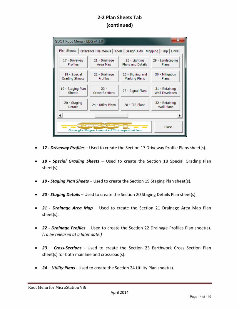
17 ‐ Driveway Profiles – Used to create the Section 17 Driveway Profile Plans sheet(s).
18 ‐ Special Grading Sheets – Used to create the Section 18 Special Grading Plan
sheet(s).
19 ‐ Staging Plan Sheets – Used to create the Section 19 Staging Plan sheet(s).
20 ‐ Staging Details – Used to create the Section 20 Staging Details Plan sheet(s).
21 ‐ Drainage Area Map – Used to create the Section 21 Drainage Area Map Plan
sheet(s).
22 ‐ Drainage Profiles – Used to create the Section 22 Drainage Profiles Plan sheet(s).
(To be released at a later date.)
23 – Cross‐Sections ‐ Used to create the Section 23 Earthwork Cross Section Plan
sheet(s) for both mainline and crossroad(s).
24 – Utility Plans ‐ Used to create the Section 24 Utility Plan sheet(s).
Page 14 of 140

RootMenuforMicroStationV8i April 2014
2‐2 Plan Sheets Tab (continued)
25 ‐ Lighting Plans and Details – Used to create the Section 25 Roadway Lighting Plan
sheet(s).
26 ‐ Signing and Marking – Used to create the Section 26 Signing and Marking Plan
sheet(s).
27 ‐ Signal Plans – Used to create the Section 27 Signal Plan sheet(s).
28 ‐ ITS Plans – Used to create the Section 28 ITS Plan sheet(s).
29 ‐ Landscaping Plans – Used to create the Section 29 Landscaping Plan sheet(s).
30 ‐ Mitigation Plans – Used to create the Section 30 Mitigation Plan sheet(s).
31 – Retaining Wall Envelopes – Used to create the Section 31 Retaining Wall Envelop
Plan sheet(s).
32 – Retaining Wall Plans ‐ Used to create the Section 32 Retaining Wall Plan sheet(s).
Page 15 of 140
RootMenuforMicroStationV8i April 2014
2‐2 Plan Sheets Tab (continued)
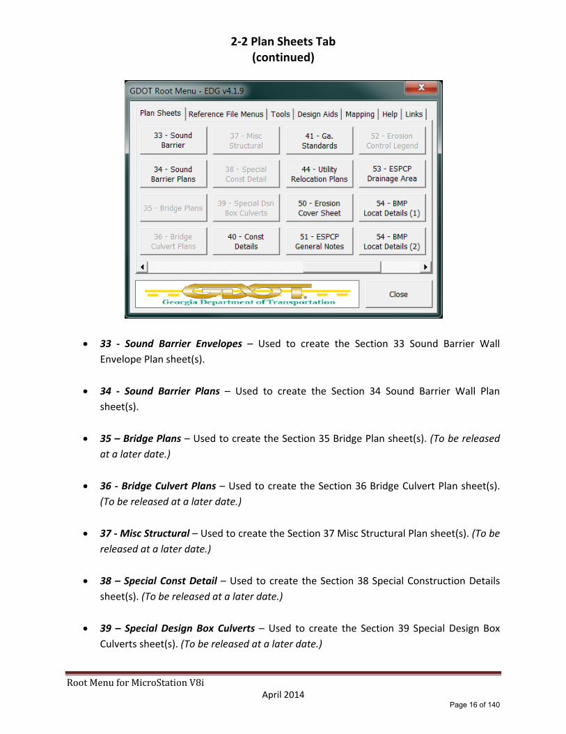
33 ‐ Sound Barrier Envelopes – Used to create the Section 33 Sound Barrier Wall
Envelope Plan sheet(s).
34 ‐ Sound Barrier Plans – Used to create the Section 34 Sound Barrier Wall Plan
sheet(s).
35 – Bridge Plans – Used to create the Section 35 Bridge Plan sheet(s). (To be released
at a later date.)
36 ‐ Bridge Culvert Plans – Used to create the Section 36 Bridge Culvert Plan sheet(s).
(To be released at a later date.)
37 ‐ Misc Structural – Used to create the Section 37 Misc Structural Plan sheet(s). (To be
released at a later date.)
38 – Special Const Detail – Used to create the Section 38 Special Construction Details
sheet(s). (To be released at a later date.)
39 – Special Design Box Culverts – Used to create the Section 39 Special Design Box
Culverts sheet(s). (To be released at a later date.)
Page 16 of 140

RootMenuforMicroStationV8i April 2014
2‐2 Plan Sheets Tab (continued)
40 – Construction Details – Used to create the Section 40 Construction Details sheet(s).
41 – Ga. Standards – Used to create the Section 41 Georgia Standards sheet(s).
44 ‐ Utility Relocation Plans – Used to create the Section 44 Utility Relocation Plan
sheet(s).
50 – Erosion Cover Sheet – Used to create the Section 50 Erosion Cover Sheet.
51 ‐ ESPCP General Notes – Used to create the Section 51 ESPCP General Notes sheet(s).
52 ‐ Erosion Control Legend – Used to create the Section 52 Erosion Control Legend
sheet(s).
53 ‐ ESPCP Drainage Area – Used to create the Section 53 ERC Drainage Area Map
sheet(s).
Page 17 of 140

RootMenuforMicroStationV8i April 2014
2‐2 Plan Sheets Tab (continued)
54 ‐ BMP Location Details (1‐5) – Used to create the Section 54 BMP Location Details for
stages 1 through 5 Plan sheet(s).
55 – EC Watershed Map‐Site Mon. – Used to create the Section 55 EC Watershed Map‐
Site Monitoring Plan sheet(s).
56 – Const Stds & Dtls for EC ONLY – Used to create the Section 56 Construction
Standards & Details for Erosion Control ONLY sheet(s).
60 ‐ Right of Way Plans‐Cover – Used to create the Section 60 Right of Way Plans‐Cover
sheet(s).
60 ‐ Right of Way Plans‐Sheets – Used to create the Section 60 Right of Way Plans‐
Sheet(s).
Page 18 of 140

RootMenuforMicroStationV8i April 2014
2‐3 Reference File Menus Tab
Sheet Layout Tools
[MAIN] Alignment / EOP
[DRNG] Drainage (Plan View)
[REQD] Required R/W & Easements
[SIGN] Signing and Pavement marking
[SGNL] Signal Plans
[ITS] ITS Plans
[UTLE] Existing Utilities
[UTLP] Proposed / Removed Utilities
[ECON] Existing Contours (To be released at a later date.)
[FCON] Future Contours (To be released at a later date.)
[LIMT] Construction Limits
[STE#] Staging and Erosion Control
[PROP] Existing Property (To be released at a later date.)
[TOPO] Existing Topography (To be released at a later date.)
[ENVE] Exist Envir & Cultural Resc
Page 19 of 140

RootMenuforMicroStationV8i April 2014
2‐3 Reference File Menus Tab (continued)
[ENVP] Prop Envir & Cultural Resc
[LNSC] Landscaping
[LGHT] Lighting
[RWTB] Right of Way (To be released at a later date.)
[TYPS] Typical Sections
[WALL] Walls (Plan View) (To be released at a later date.)
[WPRO] Walls (Profile View) (To be released at a later date.)
[CNLY] Const Layout (To be released at a later date.)
[BRDG] Bridge Plans (To be released at a later date.)
[CNCP‐E] Concept Plans – Existing
[CNCP‐P] Concept Plans – Proposed
[HLT] Concept Plans H, L & Typs (To be released at a later date.)
[RAST] Raster Images (To be released at a later date.)
[QUAD] Quad Maps (To be released at a later date.)
[MNTC] Maintenance (To be released at a later date.)
[QTYS] Summary of Quantities (To be released at a later date.)
Page 20 of 140

RootMenuforMicroStationV8i April 2014
2‐3 Reference File Menus Tab (continued)
[Sheet Layout] Sheet Layout (To be released at a later date.)
[REDLINE] Redline Export (To be released at a later date.)
Page 21 of 140

RootMenuforMicroStationV8i April 2014
2‐4 Tools Tab
LevelWorks – Tool to assist users in turning on and off DGN Levels by plan sections.
GDOT Plotting – GPlot PDF plotting utilities.
View – Fit All
View – Fit Active
View – Fit Reference
View – Update All
Window Area
Pan View
Level Manager
Levels off by Element
Active Angle by 2 Points
Construct Perpendicular To
Shift Linestyle Elements
Create Ref/Plan sheets files
Customize Function Keys (To be released at a later date.)
Active Scale = 1
Page 22 of 140

RootMenuforMicroStationV8i April 2014
2‐4 Tools Tab (continued)
Active Scale = 2
Active Scale = 20
Active Scale = 50
Active Scale = 100
Active Angle = 0
Active Angle = 90
Active Angle = 180
Active Angle = 270
Page 23 of 140

RootMenuforMicroStationV8i April 2014
2‐5 Design Aids Tab
AutoTURN v8.2 – Opens the Transoft Solutions AutoTURN swept path analysis software (if installed).
AutoTURN User Guide – Opens the AutoTURN User Guide.
TORUS v4 – Opens the Transoft Solutions TORUS modern roundabout design software (if installed).
TORUS User Guide – Opens the TORUS User Guide.
Page 24 of 140

RootMenuforMicroStationV8i April 2014
2‐6 MAPPING Tab
TOPO to UTIL (To be released at a later date.)
GridTic (To be released at a later date.)
Page 25 of 140
RootMenuforMicroStationV8i April 2014
2‐7 HELP Tab
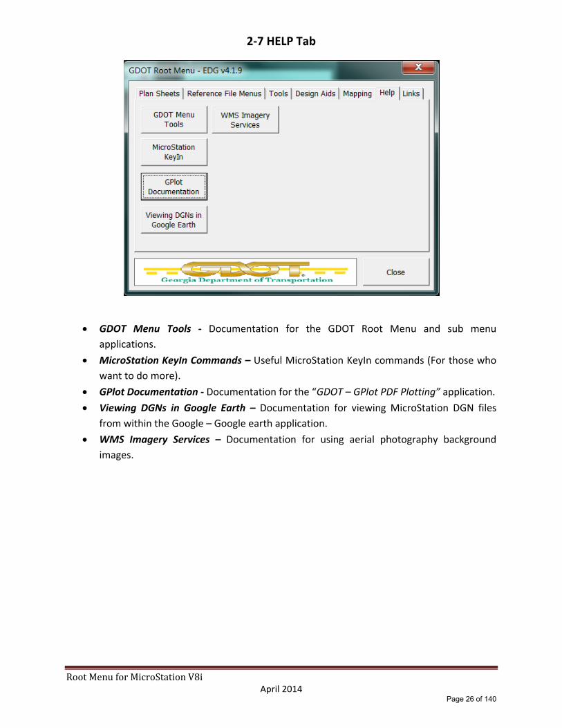
GDOT Menu Tools ‐ Documentation for the GDOT Root Menu and sub menu
applications.
MicroStation KeyIn Commands – Useful MicroStation KeyIn commands (For those who
want to do more).
GPlot Documentation ‐ Documentation for the “GDOT – GPlot PDF Plotting” application.
Viewing DGNs in Google Earth – Documentation for viewing MicroStation DGN files
from within the Google – Google earth application.
WMS Imagery Services – Documentation for using aerial photography background
images.
Page 26 of 140

RootMenuforMicroStationV8i April 2014
2‐8 Links Tab
PPG – Opens the current version of the GDOT Plan Presentation Guide from the GDOT
R.O.A.D.S. web‐page in your default web browser. (Requires external internet
connection.) http://www.dot.ga.gov/doingbusiness/PoliciesManuals/roads/Plan/Plan_Presentation_Guide.pdf
EDG – Opens the current version of the GDOT Electronic Data Guidelines PDF from the
GDOT R.O.A.D.S. web‐page in your default web browser. (Requires external internet
connection.) http://www.dot.ga.gov/doingbusiness/PoliciesManuals/roads/ElectronicData/Electronic_Data_Guidelines
Google – Opens Google web‐page in your default web browser. (Requires external
internet connection.) http://www.google.com/
R.O.A.D.S. – Opens the GDOT R.O.A.D.S. web‐page in your default web browser.
(Requires external internet connection.) http://www.dot.ga.gov/doingbusiness/PoliciesManuals/roads/Pages/default.aspx
Page 27 of 140

3-1 Plan Sheets - Expanded
The following sections provide an expanded description of the functions of the GDOT Root Menu Plan Sheets section that is included in the GDOT Workspace for MicroStation V8i.
Page 28 of 140
RootMenuforMicroStationV8i April 2014
3‐2 DGN Reference Files/Sheet Builder
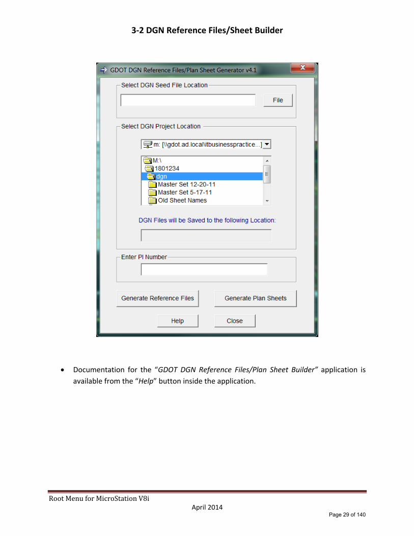
Documentation for the “GDOT DGN Reference Files/Plan Sheet Builder” application is
available from the “Help” button inside the application.
Page 29 of 140

RootMenuforMicroStationV8i April 2014
3‐3 01‐Cover Sheet
Attach Reference Files – Attaches reference files to the Cover Sheet DGN file as per the EDG requirements.
Place Fence Block / Place Fence Shape – Use to place a Fence Shape or Block to be used for Clipping the reference files.
Clip Boundary & File Design – Clips reference files and saves the view settings.
Place Cover Sheet Cell – Places the “CONCOV” cell from the GDOT‐GN‐SHEETS cell library at a default scale of 500. User may over‐ride the default scale after the command has been selected by keying in “AS=1000” etc… before pressing the Data Button.
Set Levels – Sets the cover sheet DGN file levels and all reference file levels as per the EDG requirements.
Place North Arrow – Places the “COVNOR” cell from the GDOT‐GN‐SHEETS cell library at a default scale of 500. User may over‐ride the default scale after the command has been selected by keying in “AS=1000” etc… before pressing the Data Button.
Place Scale Bar – Opens the GDOT‐GN‐SHEETS cell library via the MicroStation Cell Selector utility. User will select the appropriate scale bar cell and place it on the Cover Sheet cell.
Enter Data Fields – Use to fill in the data fields on the Cover Sheet cell. This command will not be disabled after use, allowing the user to use this command as needed without have to use the “Reset” button.
Turn off Enter Data Fields – Turns off the Data Fields for View 1.
File Design – Saves the current view settings.
Save Plotting View – Saves the plotting view from View 1 for use by the GPlot Utility.
Reset – Enables any disabled commands to allow those commands to be accessed multiple times.
Close – Closes the “01 – Cover Sheet” menu and returns the user to the “Root Menu”.
Page 30 of 140

RootMenuforMicroStationV8i April 2014
3‐4 02‐Index Sheet
Place Index Sheet Cell – Places the “GPLN” cell from the GDOT‐GN‐SHEETS cell library at a scale of 1.
Set Levels – Sets the index sheet DGN file levels as per the EDG requirements.
Include the Index Text File – Imports an ASCII text file to fill in the required index information. This file must be in the correct format. An example text file is included in the CADAll download. \GDOT_V8i\Corporate_Workspace\MicroStation\GDOT_Help\Documents\02‐Index.txt
Include Ga. Std. Text File – Imports an ASCII text file to fill in the required index information for the Georgia Standards. This file must be in the correct format. An example text file is included in the CADAll download. \GDOT_V8i\Corporate_Workspace\MicroStation\GDOT_Help\Documents\02‐Index_Standards.txt
Include Const. Dtls. Text File ‐ Imports an ASCII text file to fill in the required index information for the Construction Details. This file must be in the correct format. An example text file is included in the CADAll download. \GDOT_V8i\Corporate_Workspace\MicroStation\GDOT_Help\Documents\02‐Index_Details.txt
Enter Data Fields – Use to fill in the data fields on the Cover Sheet cell. This command will not be disabled after use, allowing the user to use this command as needed without have to use the “Reset” button.
Turn off Enter Data Fields – Turns off the Data Fields for View 1.
Place GDOT Logo x Scale – Places the “GLOGO” cell from the GDOT‐GN‐SHEETS cell library at a scale of 1.
File Design – Saves the current view settings.
Save Plotting View – Saves the plotting view from View 1 for use by the GPlot Utility.
Reset – Enables any disabled commands to allow those commands to be accessed multiple times.
Close – Closes the “02 – Index Sheet Menu” and returns the user to the “Root Menu”.
Page 31 of 140

RootMenuforMicroStationV8i April 2014
3‐5 03‐Revision Summary Sheet
Place Rev Sum Sheet Cell – Places the “GPLN” cell from the GDOT‐GN‐SHEETS cell library at a scale of 1.
Set Levels – Sets the Revision Summary sheet DGN file levels as per the EDG requirements.
Include the Rev Sum Text file – Imports an ASCII text file to fill in the required Revision Summary information. This file must be in the correct format. An example text file is included in the CADAll download. \GDOT_V8i\Corporate_Workspace\MicroStation\GDOT_Help\Documents\03‐Revision_Summary.txt
Enter Data Fields – Use to fill in the data fields on the Cover Sheet cell. This command will not be disabled after use, allowing the user to use this command as needed without have to use the “Reset” button.
Turn off Enter Data Fields – Turns off the Data Fields for View 1.
Place GDOT Logo – Places the “GLOGO” cell from the GDOT‐GN‐SHEETS cell library at a scale of 1.
File Design – Saves the current view settings.
Save Plotting View – Saves the plotting view from View 1 for use by the GPlot Utility.
Reset – Enables any disabled commands to allow those commands to be accessed multiple times.
Close – Closes the “03 – Revision Summary Sheet” menu and returns the user to the “Root Menu”.
Page 32 of 140

RootMenuforMicroStationV8i April 2014
3‐6 04 General Notes
Place Gen Notes Sheet Cell – Places the “GPLN” cell from the GDOT‐GN‐SHEETS cell library at a scale of 1.
Set Levels – Sets the sheet DGN file levels as per the EDG requirements.
Enter Data Fields – Use to fill in the data fields on the Cover Sheet cell. This command will not be disabled after use, allowing the user to use this command as needed without have to use the “Reset” button.
Turn off Enter Data Fields – Turns off the Data Fields for View 1.
Place GDOT Logo 1 Scale – Places the “GLOGO” cell from the GDOT‐GN‐SHEETS cell library at a scale of 1.
File Design – Saves the current view settings.
Save Plotting View – Saves the plotting view from View 1 for use by the GPlot Utility.
Remaining buttons (above the slider bar) – Place cells as described on each button.
Reset Buttons – Enables any disabled commands to allow those commands to be accessed multiple times.
Close – Closes the “04 – General Notes Menu” and returns the user to the “Root Menu”.
Page 33 of 140

RootMenuforMicroStationV8i April 2014
3‐7 05‐Typical Sections
Attach Reference File – Attaches the TYPS reference file to the Typical Section Sheet DGN file as per the EDG requirements. (Please note this step is optional. The user may place multiple typical section sheets in a single DGN file. In addition the user may place all typical section cells directly in the sheet file.)
Set Reference File Levels – Sets the TYPS reference file levels as per the EDG requirements. (Please note that as with the Attach Reference File command this step is not required unless the user is utilizing the TYPS reference file.)
Place x Scale Plan Sheet Cell – Places the “GPLN” cell from the GDOT‐GN‐SHEETS cell library at a scale of 5, 10 or 20.
Set Sheet Levels – Sets the sheet DGN file levels as per the EDG requirements.
Place x Scale Bar Cell – Places the scale bar cell at a scale of 5, 10 or 20.
Place GDOT Logo x Scale – Places the “GLOGO” cell from the GDOT‐GN‐SHEETS cell library at a scale of 20, 50 or 100.
Place Typical Section Cells – Closes the “05 – Typical Sections Menu” and opens the “[TYPS] Dgn” menu to allow the user to place typical section cells as required.
Enter Data Fields – Use to fill in the data fields on the Cover Sheet cell. This command will not be disabled after use, allowing the user to use this command as needed without have to use the “Reset” button.
Turn off Enter Data Fields – Turns off the Data Fields for View 1.
File Design – Saves the current view settings.
Save Plotting View – Saves the plotting view from View 1 for use by the GPlot Utility.
Turn off Vevicle/Ped – Turns off levels displaying the vehicle and pedestrian cells.
Turn on Vehicle/Ped ‐ Turns on levels displaying the vehicle and pedestrian cells.
Page 34 of 140

RootMenuforMicroStationV8i April 2014
3‐7 05‐Typical Sections (continued)
Reset Buttons – Enables any disabled commands to allow those commands to be accessed multiple times.
Close – Closes the “05 – Typical Sections Menu” and returns the user to the “Root Menu”.
Page 35 of 140

RootMenuforMicroStationV8i April 2014
3‐8 06 Summary of Quantities
Place Plan Sheet Cell – Places the “GPLN” cell from the GDOT‐GN‐SHEETS cell library at a scale of 1.
Set Levels – Sets the sheet DGN file levels as per the EDG requirements.
Enter Data Fields – Use to fill in the data fields on the Cover Sheet cell. This command will not be disabled after use, allowing the user to use this command as needed without have to use the “Reset” button.
Turn off Enter Data Fields – Turns off the Data Fields for View 1.
Place GDOT Logo – Places the “GLOGO” cell from the GDOT‐GN‐SHEETS cell library at a scale of 1.
File Design – Saves the current view settings.
Save Plotting View – Saves the plotting view from View 1 for use by the GPlot Utility.
File Design – Saves the current view settings.
Remaining buttons (above the slider bar) – Place cells as described on each button.
Reset – Enables any disabled commands to allow those commands to be accessed multiple times.
Close – Closes the “06 – Summary of Quantities” menu and returns the user to the “Root Menu”.
Page 36 of 140

RootMenuforMicroStationV8i April 2014
3‐9 07‐Quantities by Amendment
Place Plan Sheet Cell – Places the “GPLN” cell from the GDOT‐GN‐SHEETS cell library at a scale of 1.
Set Levels – Sets the sheet DGN file levels as per the EDG requirements.
Enter Data Fields – Use to fill in the data fields on the Cover Sheet cell. This command will not be disabled after use, allowing the user to use this command as needed without have to use the “Reset” button.
Turn off Enter Data Fields – Turns off the Data Fields for View 1.
Place GDOT Logo – Places the “GLOGO” cell from the GDOT‐GN‐SHEETS cell library at a scale of 1.
File Design – Saves the current view settings.
Save Plotting View – Saves the plotting view from View 1 for use by the GPlot Utility.
File Design – Saves the current view settings.
Remaining buttons (above the slider bar) – Place cells as described on each button.
Reset – Enables any disabled commands to allow those commands to be accessed multiple times.
Close – Closes the “07 – Quantities by Amendment” menu and returns the user to the “Root Menu”.
Page 37 of 140

RootMenuforMicroStationV8i April 2014
3‐10 08‐Quantities use on Construction
Place Plan Sheet Cell – Places the “GPLN” cell from the GDOT‐GN‐SHEETS cell library at a scale of 1.
Set Levels – Sets the sheet DGN file levels as per the EDG requirements.
Enter Data Fields – Use to fill in the data fields on the Cover Sheet cell. This command will not be disabled after use, allowing the user to use this command as needed without have to use the “Reset” button.
Turn off Enter Data Fields – Turns off the Data Fields for View 1.
Place GDOT Logo – Places the “GLOGO” cell from the GDOT‐GN‐SHEETS cell library at a scale of 1.
File Design – Saves the current view settings.
Save Plotting View – Saves the plotting view from View 1 for use by the GPlot Utility.
File Design – Saves the current view settings.
Remaining buttons (above the slider bar) – Place cells as described on each button.
Reset – Enables any disabled commands to allow those commands to be accessed multiple times.
Close – Closes the “08 – Quantities use on Construction” menu and returns the user to the “Root Menu”.
Page 38 of 140

RootMenuforMicroStationV8i April 2014
3‐11 10‐Traffic Diagram Sheets
Place Plan Sheet Cell – Places the “GPLN” cell from the GDOT‐GN‐SHEETS cell library at a default scale of 20. User may over‐ride the default scale after the command has been selected by keying in “AS=1000” etc… before pressing the Data Button.
Set Levels – Sets the sheet DGN file levels and the reference file levels as per the EDG requirements.
Choose Intersection – Opens the MicroStation “Cell Selector” utility to allow user to place various intersection cells.
Enter Data Fields – Use to fill in the data fields on the Plan Sheet cell. This command will not be disabled after use, allowing the user to use this command as needed without have to use the “Reset” button.
Turn on Data Fields – Turns on the Data Fields for View 1.
Turn off Data Fields – Turns off the Data Fields for View 1.
Place GDOT Logo – Places the “GLOGO” cell from the GDOT‐GN‐SHEETS cell library at a scale of 20. User may over‐ride the default scale after the command has been selected by keying in “AS=1000” etc… before pressing the Data Button.
File Design – Saves the current view settings.
Save Plotting View – Saves the plotting view from View 1 for use by the GPlot Utility.
Setup Grid – Turns the design grid ticks on. (Optional)
Reset – Enables any disabled commands to allow those commands to be accessed multiple times.
Close – Closes the “10 – Traffic Diagram Sheets” menu and returns the user to the “Root Menu”.
Page 39 of 140

RootMenuforMicroStationV8i April 2014
3‐11 10‐Traffic Diagram Sheets (Continued)
Road Name – Places the “GPLN” cell from the GDOT‐GN‐SHEETS cell library at a default scale of 20. User may over‐ride the default scale after the command has been selected by keying in “AS=1000” etc… before pressing the Data Button.
ADT – Sets the sheet DGN file levels and the reference file levels as per the EDG requirements.
DHV – Opens the MicroStation “Cell Selector” utility to allow user to place various intersection cells.
% Trucks – Use to fill in the data fields on the Plan Sheet cell. This command will not be disabled after use, allowing the user to use this command as needed without have to use the “Reset” button.
Title Block No. – Turns on the Data Fields for View 1.
Larger Text – Turns off the Data Fields for View 1.
Reset – Enables any disabled commands to allow those commands to be accessed multiple times.
Close – Closes the “10 – Traffic Diagram Sheets” menu and returns the user to the “Root Menu”.
Page 40 of 140

RootMenuforMicroStationV8i April 2014
3‐12 11‐Construction Layout
Attach Reference Files – Attaches the reference DGN files as per the EDG requirements.
Set Reference File Levels – Sets the reference DGN file levels as per the EDG requirements.
Place Plan Sheet Cell – Places the “GPLN” cell from the GDOT‐GN‐SHEETS cell library at a default scale of 500. User may over‐ride the default scale after the command has been selected by keying in “AS=1000” etc… before pressing the Data Button.
Set Levels – Sets the sheet DGN file levels and the reference file levels as per the EDG requirements.
Place North Arrow – Places the “NARROW” cell from the GDOT‐GN‐SHEETS cell library at a default scale of 500. User may over‐ride the default scale after the command has been selected by keying in “AS=1000” etc… before pressing the Data Button.
Select Scale – Opens the GDOT‐GN‐SHEETS cell library via the MicroStation Cell Selector utility. User will select the appropriate scale bar cell and place it on the Cover Sheet cell.
Place Match Line Text 500 Scale ‐ Places match line text for use at either end of the plan sheet coverage limits at a scale of 500.
Enter Data Fields – Use to fill in the data fields on the Cover Sheet cell. This command will not be disabled after use, allowing the user to use this command as needed without have to use the “Reset” button.
Turn off Enter Data Fields – Turns off the Data Fields for View 1.
Place GDOT Logo – Places the “GLOGO” cell from the GDOT‐GN‐SHEETS cell library at a scale of 500. User may over‐ride the default scale after the command has been selected by keying in “AS=1000” etc… before pressing the Data Button.
File Design – Saves the current view settings.
Save Plotting View – Saves the plotting view from View 1 for use by the GPlot Utility.
Reset – Enables any disabled commands to allow those commands to be accessed multiple times.
Close – Closes the “11 – Const. Layout Menu” and returns the user to the “Root Menu”.
Page 41 of 140

RootMenuforMicroStationV8i April 2014
3‐13 12‐Miscellaneous Maps
Attach Reference Files – Attaches the reference DGN files as per the EDG requirements.
Place Fence Block / Place Fence Shape – Use to place a Fence Shape or Block to be used for Clipping the reference files.
Reference Clip Boundary ‐ Clips reference files and saves the view settings.
Place Plan Sheet Cell – Places the “GPLN” cell from the GDOT‐GN‐SHEETS cell library at a default scale of 500. User may over‐ride the default scale after the command has been selected by keying in “AS=1000” etc… before pressing the Data Button.
Set Levels – Sets the sheet DGN file levels and the reference file levels as per the EDG requirements.
Place North Arrow – Places the “NARROW” cell from the GDOT‐GN‐SHEETS cell library at a default scale of 500. User may over‐ride the default scale after the command has been selected by keying in “AS=1000” etc… before pressing the Data Button.
Select Scale – Opens the GDOT‐GN‐SHEETS cell library via the MicroStation Cell Selector utility. User will select the appropriate scale bar cell and place it on the Cover Sheet cell.
Enter Data Fields – Use to fill in the data fields on the Cover Sheet cell. This command will not be disabled after use, allowing the user to use this command as needed without have to use the “Reset” button.
Turn off Enter Data Fields – Turns off the Data Fields for View 1.
Place GDOT Logo – Places the “GLOGO” cell from the GDOT‐GN‐SHEETS cell library at a scale of 500. User may over‐ride the default scale after the command has been selected by keying in “AS=1000” etc… before pressing the Data Button.
File Design – Saves the current view settings.
Save Plotting View – Saves the plotting view from View 1 for use by the GPlot Utility.
Reset – Enables any disabled commands to allow those commands to be accessed multiple times.
Close – Closes the “12 – Misc. Maps Menu” and returns the user to the “Root Menu”.
Page 42 of 140

RootMenuforMicroStationV8i April 2014
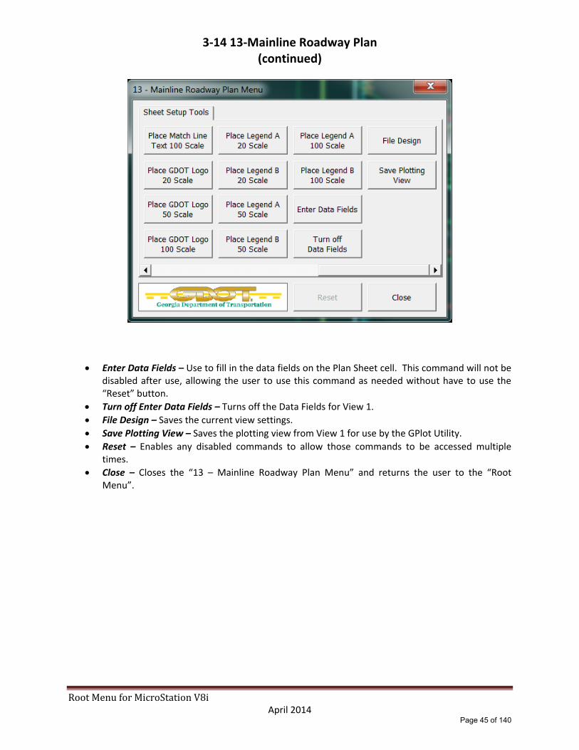
3‐14 13‐Mainline Roadway Plan
Attach Sheet Layout – Attaches the SheetLayout.dgn file.
Turn Reference File Levels On – Turns on the SheetLayout DGN reference file levels ONLY.
Window Area – Window area to the appropriate area to place the new plan sheet cell.
Place North Arrow x Scale – Places the “NARROW” cell from the GDOT‐GN‐SHEETS cell library at the scale identified on each of the three options.
Rotate View by Elements – User will enter a Data button on the top line of the clip border for the appropriate sheet to be created.
Copy Match Lines – Allows user to copy the match lines from the SheetLayout DGN reference file into the plan sheet file.
Place Fence Block / Place Fence Shape – Use to place a Fence Shape or Block to be used for Clipping the reference files.
Place x Scale Plan Sheet – Places the “GPLN” cell from the GDOT‐GN‐SHEETS cell library at the scale identified on each of the three options.
Set Levels – Sets the sheet DGN file levels and the reference file levels as per the EDG requirements.
Detach Sheet Layout – Detaches the SheetLayout.DGN reference file.
Attach Reference Files – Attaches the reference DGN files as per the EDG requirements.
Page 43 of 140

RootMenuforMicroStationV8i April 2014
3‐14 13‐Mainline Roadway Plan (continued)
Set Reference File Levels – Sets the reference dgn file levels as per the EDG requirements.
Clip Boundary ‐ Clips reference dgn files.
File Design – Saves the current view settings.
Place x Scale Bar Cell – Places the scale bar cell at a scale of 20, 50 or 100.
Place Match Line Text x Scale – Places match line text for use at either end of the plan sheet coverage limits at a scale of 20, 50 or 100.
Place GDOT Logo x Scale – Places the “GLOGO” cell from the GDOT‐GN‐SHEETS cell library at a scale of 20, 50 or 100.
Place Legend … ‐ Place legend cells at a scale of 20, 50 or 100.
Page 44 of 140
RootMenuforMicroStationV8i April 2014
3‐14 13‐Mainline Roadway Plan (continued)
Enter Data Fields – Use to fill in the data fields on the Plan Sheet cell. This command will not be disabled after use, allowing the user to use this command as needed without have to use the “Reset” button.
Turn off Enter Data Fields – Turns off the Data Fields for View 1.
File Design – Saves the current view settings.
Save Plotting View – Saves the plotting view from View 1 for use by the GPlot Utility.
Reset – Enables any disabled commands to allow those commands to be accessed multiple times.
Close – Closes the “13 – Mainline Roadway Plan Menu” and returns the user to the “Root Menu”.
Page 45 of 140

RootMenuforMicroStationV8i April 2014
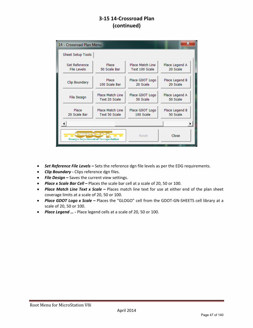
3‐15 14‐Crossroad Plan
Attach Sheet Layout – Attaches the SheetLayout.dgn file.
Turn Reference File Levels On – Turns on the SheetLayout DGN reference file levels ONLY.
Window Area – Window area to the appropriate area to place the new plan sheet cell.
Place North Arrow x Scale – Places the “NARROW” cell from the GDOT‐GN‐SHEETS cell library at the scale identified on each of the three options.
Rotate View by Elements – User will enter a Data button on the top line of the clip border for the appropriate sheet to be created.
Copy Match Lines – Allows user to copy the match lines from the SheetLayout DGN reference file into the plan sheet file.
Place Fence Block / Place Fence Shape – Use to place a Fence Shape or Block to be used for Clipping the reference files.
Place x Scale Plan Sheet – Places the “GPLN” cell from the GDOT‐GN‐SHEETS cell library at the scale identified on each of the three options.
Set Levels – Sets the sheet DGN file levels and the reference file levels as per the EDG requirements.
Detach Sheet Layout – Detaches the SheetLayout.DGN reference file.
Attach Reference Files – Attaches the reference DGN files as per the EDG requirements.
Page 46 of 140
RootMenuforMicroStationV8i April 2014
3‐15 14‐Crossroad Plan (continued)
Set Reference File Levels – Sets the reference dgn file levels as per the EDG requirements.
Clip Boundary ‐ Clips reference dgn files.
File Design – Saves the current view settings.
Place x Scale Bar Cell – Places the scale bar cell at a scale of 20, 50 or 100.
Place Match Line Text x Scale – Places match line text for use at either end of the plan sheet coverage limits at a scale of 20, 50 or 100.
Place GDOT Logo x Scale – Places the “GLOGO” cell from the GDOT‐GN‐SHEETS cell library at a scale of 20, 50 or 100.
Place Legend … ‐ Place legend cells at a scale of 20, 50 or 100.
Page 47 of 140

RootMenuforMicroStationV8i April 2014
3‐15 14‐Crossroad Plan (continued)
Enter Data Fields – Use to fill in the data fields on the Plan Sheet cell. This command will not be disabled after use, allowing the user to use this command as needed without have to use the “Reset” button.
Turn off Enter Data Fields – Turns off the Data Fields for View 1.
File Design – Saves the current view settings.
Save Plotting View – Saves the plotting view from View 1 for use by the GPlot Utility.
Reset – Enables any disabled commands to allow those commands to be accessed multiple times.
Close – Closes the “14 – Crossroad Plan Menu” and returns the user to the “Root Menu”.
Page 48 of 140
RootMenuforMicroStationV8i April 2014
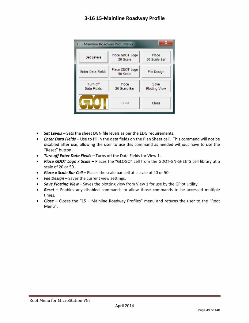
3‐16 15‐Mainline Roadway Profile
Set Levels – Sets the sheet DGN file levels as per the EDG requirements.
Enter Data Fields – Use to fill in the data fields on the Plan Sheet cell. This command will not be disabled after use, allowing the user to use this command as needed without have to use the “Reset” button.
Turn off Enter Data Fields – Turns off the Data Fields for View 1.
Place GDOT Logo x Scale – Places the “GLOGO” cell from the GDOT‐GN‐SHEETS cell library at a scale of 20 or 50.
Place x Scale Bar Cell – Places the scale bar cell at a scale of 20 or 50.
File Design – Saves the current view settings.
Save Plotting View – Saves the plotting view from View 1 for use by the GPlot Utility.
Reset – Enables any disabled commands to allow those commands to be accessed multiple times.
Close – Closes the “15 – Mainline Roadway Profiles” menu and returns the user to the “Root Menu”.
Page 49 of 140

RootMenuforMicroStationV8i April 2014
3‐17 16‐Xroad Profile
Set Levels – Sets the sheet DGN file levels as per the EDG requirements.
Enter Data Fields – Use to fill in the data fields on the Plan Sheet cell. This command will not be disabled after use, allowing the user to use this command as needed without have to use the “Reset” button.
Turn off Enter Data Fields – Turns off the Data Fields for View 1.
Place GDOT Logo x Scale – Places the “GLOGO” cell from the GDOT‐GN‐SHEETS cell library at a scale of 20 or 50.
Place x Scale Bar Cell – Places the scale bar cell at a scale of 20 or 50.
File Design – Saves the current view settings.
Save Plotting View – Saves the plotting view from View 1 for use by the GPlot Utility.
Reset – Enables any disabled commands to allow those commands to be accessed multiple times.
Close – Closes the “16 – Xroad Profiles Menu” menu and returns the user to the “Root Menu”.
Page 50 of 140

RootMenuforMicroStationV8i April 2014
3‐18 17‐Driveway Profile
Set Levels – Sets the sheet DGN file levels as per the EDG requirements.
Enter Data Fields – Use to fill in the data fields on the Plan Sheet cell. This command will not be disabled after use, allowing the user to use this command as needed without have to use the “Reset” button.
Turn off Enter Data Fields – Turns off the Data Fields for View 1.
Place GDOT Logo x Scale – Places the “GLOGO” cell from the GDOT‐GN‐SHEETS cell library at a scale of 20 or 50.
Place x Scale Bar Cell – Places the scale bar cell at a scale of 20 or 50.
File Design – Saves the current view settings.
Save Plotting View – Saves the plotting view from View 1 for use by the GPlot Utility.
Reset – Enables any disabled commands to allow those commands to be accessed multiple times.
Close – Closes the “17 – Driveway Profiles Menu” and returns the user to the “Root Menu”.
Page 51 of 140

RootMenuforMicroStationV8i April 2014
3‐19 18‐Special Grading Sheets
Attach Reference Files – Attaches the reference DGN files as per the EDG requirements.
Set Reference File Levels – Sets the reference dgn file levels as per the EDG requirements.
Place Plan Sheet Cell – Places the “GPLN” cell from the GDOT‐GN‐SHEETS cell library at a default scale of 500. User may over‐ride the default scale after the command has been selected by keying in “AS=1000” etc… before pressing the Data Button.
Set Levels – Sets the sheet DGN file levels and the reference DGN file levels as per the EDG requirements.
Place North Arrow – Places the “NARROW” cell from the GDOT‐GN‐SHEETS cell library at a default scale of 500. User may over‐ride the default scale after the command has been selected by keying in “AS=1000” etc… before pressing the Data Button.
Place Scale Bar – Opens the GDOT‐GN‐SHEETS cell library via the MicroStation Cell Selector utility. User will select the appropriate scale bar cell and place it on the Cover Sheet cell.
Enter Data Fields – Use to fill in the data fields on the Plan Sheet cell. This command will not be disabled after use, allowing the user to use this command as needed without have to use the “Reset” button.
Turn off Enter Data Fields – Turns off the Data Fields for View 1.
Place GDOT Logo – Places the “GLOGO” cell from the GDOT‐GN‐SHEETS cell library at a scale of 500. User may over‐ride the default scale after the command has been selected by keying in “AS=1000” etc… before pressing the Data Button.
File Design – Saves the current view settings.
Save Plotting View – Saves the plotting view from View 1 for use by the GPlot Utility.
Reset – Enables any disabled commands to allow those commands to be accessed multiple times.
Close – Closes the “18 – Special Grading Sheets” menu and returns the user to the “Root Menu”.
Page 52 of 140

RootMenuforMicroStationV8i April 2014
3‐20 19‐Staging Plan
“Staging Plans – STE1” tab
Select STE1 through STE5 for appropriate stage. All five STE menus contain the same commands.
Attach Sheet Layout – Attaches the SheetLayout.dgn file.
Turn Reference File Levels On – Turns on the SheetLayout DGN reference file levels ONLY.
Window Area – Window area to the appropriate area to place the new plan sheet cell.
Place North Arrow x Scale – Places the “NARROW” cell from the GDOT‐GN‐SHEETS cell library at the scale identified on each of the three options.
Rotate View by Elements – User will enter a Data button on the top line of the clip border for the appropriate sheet to be created.
Copy Match Lines – Allows user to copy the match lines from the SheetLayout DGN reference file into the plan sheet file.
Place Fence Block / Place Fence Shape – Use to place a Fence Shape or Block to be used for Clipping the reference files.
Place x Scale Plan Sheet – Places the “GPLN” cell from the GDOT‐GN‐SHEETS cell library at the scale identified on each of the three options.
Set Levels – Sets the sheet DGN file levels and the reference file levels as per the EDG requirements.
Detach Sheet Layout – Detaches the SheetLayout.DGN reference file.
Attach Reference Files – Attaches the reference DGN files as per the EDG requirements.
Page 53 of 140

RootMenuforMicroStationV8i April 2014
3‐20 19‐Staging Plan (continued)
“Staging Plans – STE1” tab
Set Reference File Levels – Sets the reference dgn file levels as per the EDG requirements.
Clip Boundary ‐ Clips reference dgn files.
File Design – Saves the current view settings.
Place x Scale Bar Cell – Places the scale bar cell at a scale of 20, 50 or 100.
Place Match Line Text x Scale – Places match line text for use at either end of the plan sheet coverage limits at a scale of 20, 50 or 100.
Place Staging Legend x Scale ‐ Place legend cells at a scale of 20, 50 or 100.
Enter Data Fields – Use to fill in the data fields on the Plan Sheet cell. This command will not be disabled after use, allowing the user to use this command as needed without have to use the “Reset” button.
Turn off Enter Data Fields – Turns off the Data Fields for View 1.
File Design – Saves the current view settings.
Save Plotting View – Saves the plotting view from View 1 for use by the GPlot Utility.
Reset – Enables any disabled commands to allow those commands to be accessed multiple times.
Close – Closes the “19 – Staging Plan Sheets Menu” and returns the user to the “Root Menu”.
Page 54 of 140

RootMenuforMicroStationV8i April 2014
3‐20 19‐Staging Plan (continued)
“Staging Profiles” tab
Select Staging Profiles for Staging Profile Sheets (all stages).
Set Levels – Sets the sheet DGN file levels as per the EDG requirements.
Enter Data Fields – Use to fill in the data fields on the Plan Sheet cell. This command will not be disabled after use, allowing the user to use this command as needed without have to use the “Reset” button.
Turn off Enter Data Fields – Turns off the Data Fields for View 1.
File Design – Saves the current view settings.
Save Plotting View – Saves the plotting view from View 1 for use by the GPlot Utility.
Reset – Enables any disabled commands to allow those commands to be accessed multiple times.
Close – Closes the “19 – Staging Plan Sheets Menu” menu and returns the user to the “Root Menu”.
Page 55 of 140

RootMenuforMicroStationV8i April 2014
3‐20 19‐Staging Plan (continued)
“Staging Cross Sections” tab
Select Staging Cross Sections for Staging Cross Section Sheets (all stages).
Set Levels – Sets the sheet DGN file levels as per the EDG requirements.
Enter Data Fields – Use to fill in the data fields on the Plan Sheet cell. This command will not be disabled after use, allowing the user to use this command as needed without have to use the “Reset” button.
Turn off Enter Data Fields – Turns off the Data Fields for View 1.
File Design – Saves the current view settings.
Save Plotting View – Saves the plotting view from View 1 for use by the GPlot Utility.
Reset – Enables any disabled commands to allow those commands to be accessed multiple times.
Close – Closes the “19 – Staging Plan Sheets Menu” and returns the user to the “Root Menu”.
Page 56 of 140

RootMenuforMicroStationV8i April 2014
3‐21 20‐Staging Details
Attach Sheet Layout – Attaches the SheetLayout.dgn file.
Turn Reference File Levels On – Turns on the SheetLayout DGN reference file levels ONLY.
Window Area – Window area to the appropriate area to place the new plan sheet cell.
Place North Arrow x Scale – Places the “NARROW” cell from the GDOT‐GN‐SHEETS cell library at the scale identified on each of the three options.
Rotate View by Elements – User will enter a Data button on the top line of the clip border for the appropriate sheet to be created.
Copy Match Lines – Allows user to copy the match lines from the SheetLayout DGN reference file into the plan sheet file.
Place x Scale Plan Sheet – Places the “GPLN” cell from the GDOT‐GN‐SHEETS cell library at the scale identified on each of the three options.
Set Levels – Sets the sheet DGN file levels and the reference file levels as per the EDG requirements.
Detach Sheet Layout – Detaches the SheetLayout.DGN reference file.
Attach Staging Detail Ref File – Attaches the Staging Detail reference file.
Place Fence Block / Place Fence Shape – Use to place a Fence Shape or Block to be used for Clipping the reference files.
Page 57 of 140

RootMenuforMicroStationV8i April 2014
3‐21 20‐Staging Details (continued)
Set Reference File Levels – Sets the staging detail reference DGN file levels.
Clip Boundary ‐ Clips reference dgn files.
File Design – Saves the current view settings.
Place x Scale Bar Cell – Places the scale bar cell at a scale of 20, 50 or 100.
Place Match Line Text x Scale – Places match line text for use at either end of the plan sheet coverage limits at a scale of 20, 50 or 100.
Place GDOT Logo x Scale – Places the “GLOGO” cell from the GDOT‐GN‐SHEETS cell library at a scale of 20, 50 or 100.
Enter Data Fields – Use to fill in the data fields on the Plan Sheet cell. This command will not be disabled after use, allowing the user to use this command as needed without have to use the “Reset” button.
Turn off Enter Data Fields – Turns off the Data Fields for View 1.
File Design – Saves the current view settings.
Save Plotting View – Saves the plotting view from View 1 for use by the GPlot Utility.
Reset – Enables any disabled commands to allow those commands to be accessed multiple times.
Close – Closes the “20 – Staging Details Menu” and returns the user to the “Root Menu”.
Page 58 of 140

RootMenuforMicroStationV8i April 2014
3‐22 21‐Drainage Area Map
Attach Reference Files – Attaches the reference DGN files as per the EDG requirements.
Set Reference File Levels – Sets the reference dgn file levels as per the EDG requirements.
Place Plan Sheet Cell – Places the “GPLN” cell from the GDOT‐GN‐SHEETS cell library at a default scale of 500. User may over‐ride the default scale after the command has been selected by keying in “AS=1000” etc… before pressing the Data Button.
Set Levels – Sets the sheet DGN file levels and the reference DGN file levels as per the EDG requirements.
Place North Arrow – Places the “NARROW” cell from the GDOT‐GN‐SHEETS cell library at a default scale of 500. User may over‐ride the default scale after the command has been selected by keying in “AS=1000” etc… before pressing the Data Button.
Place GDOT Logo – Places the “GLOGO” cell from the GDOT‐GN‐SHEETS cell library at a scale of 500. User may over‐ride the default scale after the command has been selected by keying in “AS=1000” etc… before pressing the Data Button.
Place Scale Bar – Opens the GDOT‐GN‐SHEETS cell library via the MicroStation Cell Selector utility. User will select the appropriate scale bar cell and place it on the Cover Sheet cell.
Enter Data Fields – Use to fill in the data fields on the Plan Sheet cell. This command will not be disabled after use, allowing the user to use this command as needed without have to use the “Reset” button.
Turn off Enter Data Fields – Turns off the Data Fields for View 1.
File Design – Saves the current view settings.
Save Plotting View – Saves the plotting view from View 1 for use by the GPlot Utility.
Reset – Enables any disabled commands to allow those commands to be accessed multiple times.
Close – Closes the “21 – Drainage Area Map” menu and returns the user to the “Root Menu”.
Page 59 of 140

RootMenuforMicroStationV8i April 2014
3‐23 22‐Drainage Profile
Set Levels – Sets the sheet DGN file levels and the reference DGN file levels as per the EDG requirements.
Enter Data Fields – Use to fill in the data fields on the Plan Sheet cell. This command will not be disabled after use, allowing the user to use this command as needed without have to use the “Reset” button.
Turn off Enter Data Fields – Turns off the Data Fields for View 1.
Place GDOT Logo – Places the “GLOGO” cell from the GDOT‐GN‐SHEETS cell library at a scale of 10. User may over‐ride the default scale after the command has been selected by keying in “AS=50” etc… before pressing the Data Button.
Place Scale Bar – Opens the GDOT‐GN‐SHEETS cell library via the MicroStation Cell Selector utility. User will select the appropriate scale bar cell and place it on the Cover Sheet cell.
Enter Data Fields – Use to fill in the data fields on the Plan Sheet cell. This command will not be disabled after use, allowing the user to use this command as needed without have to use the “Reset” button.
Turn off Enter Data Fields – Turns off the Data Fields for View 1.
File Design – Saves the current view settings.
Save Plotting View – Saves the plotting view from View 1 for use by the GPlot Utility.
Reset – Enables any disabled commands to allow those commands to be accessed multiple times.
Close – Closes the “22 – Drainage Profile” menu and returns the user to the “Root Menu”.
Page 60 of 140
RootMenuforMicroStationV8i April 2014
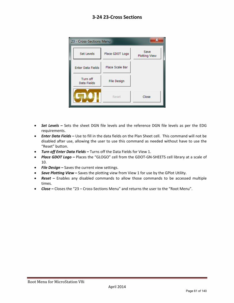
3‐24 23‐Cross Sections
Set Levels – Sets the sheet DGN file levels and the reference DGN file levels as per the EDG requirements.
Enter Data Fields – Use to fill in the data fields on the Plan Sheet cell. This command will not be disabled after use, allowing the user to use this command as needed without have to use the “Reset” button.
Turn off Enter Data Fields – Turns off the Data Fields for View 1.
Place GDOT Logo – Places the “GLOGO” cell from the GDOT‐GN‐SHEETS cell library at a scale of 10.
File Design – Saves the current view settings.
Save Plotting View – Saves the plotting view from View 1 for use by the GPlot Utility.
Reset – Enables any disabled commands to allow those commands to be accessed multiple times.
Close – Closes the “23 – Cross‐Sections Menu” and returns the user to the “Root Menu”.
Page 61 of 140

RootMenuforMicroStationV8i April 2014
3‐25 24‐Utility Plan
Attach Sheet Layout – Attaches the SheetLayout.dgn file.
Turn Reference File Levels On – Turns on the SheetLayout DGN reference file levels ONLY.
Window Area – Window area to the appropriate area to place the new plan sheet cell.
Place North Arrow x Scale – Places the “NARROW” cell from the GDOT‐GN‐SHEETS cell library at the scale identified on each of the three options.
Rotate View by Elements – User will enter a Data button on the top line of the clip border for the appropriate sheet to be created.
Copy Match Lines – Allows user to copy the match lines from the SheetLayout DGN reference file into the plan sheet file.
Place Fence Block / Place Fence Shape – Use to place a Fence Shape or Block to be used for Clipping the reference files.
Place x Scale Plan Sheet – Places the “GPLN” cell from the GDOT‐GN‐SHEETS cell library at the scale identified on each of the three options.
Set Levels – Sets the sheet DGN file levels and the reference file levels as per the EDG requirements.
Detach Sheet Layout – Detaches the SheetLayout.DGN reference file.
Attach Reference Files – Attaches the reference DGN files as per the EDG requirements.
Page 62 of 140

RootMenuforMicroStationV8i April 2014
3‐25 24‐Utility Plan (continued)
Set Reference File Levels – Sets the reference dgn file levels as per the EDG requirements.
Clip Boundary ‐ Clips reference dgn files.
File Design – Saves the current view settings.
Place x Scale Bar Cell – Places the scale bar cell at a scale of 20, 50 or 100.
Place Match Line Text x Scale – Places match line text for use at either end of the plan sheet coverage limits at a scale of 20, 50 or 100.
Place GDOT Logo x Scale – Places the “GLOGO” cell from the GDOT‐GN‐SHEETS cell library at a scale of 20, 50 or 100.
Enter Data Fields – Use to fill in the data fields on the Plan Sheet cell. This command will not be disabled after use, allowing the user to use this command as needed without have to use the “Reset” button.
Turn off Enter Data Fields – Turns off the Data Fields for View 1.
File Design – Saves the current view settings.
Save Plotting View – Saves the plotting view from View 1 for use by the GPlot Utility.
Reset – Enables any disabled commands to allow those commands to be accessed multiple times.
Close – Closes the “24 – Utility Plans Menu” and returns the user to the “Root Menu”.
Page 63 of 140

RootMenuforMicroStationV8i April 2014
3‐26 25‐Lighting Plans and Details
Attach Sheet Layout – Attaches the SheetLayout.dgn file.
Turn Reference File Levels On – Turns on the SheetLayout DGN reference file levels ONLY.
Window Area – Window area to the appropriate area to place the new plan sheet cell.
Place North Arrow x Scale – Places the “NARROW” cell from the GDOT‐GN‐SHEETS cell library at the scale identified on each of the three options.
Rotate View by Elements – User will enter a Data button on the top line of the clip border for the appropriate sheet to be created.
Copy Match Lines – Allows user to copy the match lines from the SheetLayout DGN reference file into the plan sheet file.
Place Fence Block / Place Fence Shape – Use to place a Fence Shape or Block to be used for Clipping the reference files.
Place x Scale Plan Sheet – Places the “GPLN” cell from the GDOT‐GN‐SHEETS cell library at the scale identified on each of the three options.
Set Levels – Sets the sheet DGN file levels and the reference file levels as per the EDG requirements.
Detach Sheet Layout – Detaches the SheetLayout.DGN reference file.
Attach Reference Files – Attaches the reference DGN files as per the EDG requirements.
Page 64 of 140

RootMenuforMicroStationV8i April 2014
3‐26 25‐Lighting Plans and Details (continued)
Set Reference File Levels – Sets the reference dgn file levels as per the EDG requirements.
Clip Boundary ‐ Clips reference dgn files.
File Design – Saves the current view settings.
Place x Scale Bar Cell – Places the scale bar cell at a scale of 20, 50 or 100.
Place Match Line Text x Scale – Places match line text for use at either end of the plan sheet coverage limits at a scale of 20, 50 or 100.
Place GDOT Logo x Scale – Places the “GLOGO” cell from the GDOT‐GN‐SHEETS cell library at a scale of 20, 50 or 100.
Enter Data Fields – Use to fill in the data fields on the Plan Sheet cell. This command will not be disabled after use, allowing the user to use this command as needed without have to use the “Reset” button.
Turn off Enter Data Fields – Turns off the Data Fields for View 1.
File Design – Saves the current view settings.
Save Plotting View – Saves the plotting view from View 1 for use by the GPlot Utility.
Reset – Enables any disabled commands to allow those commands to be accessed multiple times.
Close – Closes the “25 – Lighting Plans and Details Menu” and returns the user to the “Root Menu”.
Page 65 of 140

RootMenuforMicroStationV8i April 2014
3‐27 26‐Signing and Marking Plan
Attach Sheet Layout – Attaches the SheetLayout.dgn file.
Turn Reference File Levels On – Turns on the SheetLayout DGN reference file levels ONLY.
Window Area – Window area to the appropriate area to place the new plan sheet cell.
Place North Arrow x Scale – Places the “NARROW” cell from the GDOT‐GN‐SHEETS cell library at the scale identified on each of the three options.
Rotate View by Elements – User will enter a Data button on the top line of the clip border for the appropriate sheet to be created.
Copy Match Lines – Allows user to copy the match lines from the SheetLayout DGN reference file into the plan sheet file.
Place Fence Block / Place Fence Shape – Use to place a Fence Shape or Block to be used for Clipping the reference files.
Place x Scale Plan Sheet – Places the “GPLN” cell from the GDOT‐GN‐SHEETS cell library at the scale identified on each of the three options.
Set Levels – Sets the sheet DGN file levels and the reference file levels as per the EDG requirements.
Detach Sheet Layout – Detaches the SheetLayout.DGN reference file.
Attach Reference Files – Attaches the reference DGN files as per the EDG requirements.
Page 66 of 140

RootMenuforMicroStationV8i April 2014
3‐27 26‐Signing and Marking Plan (continued)
Set Reference File Levels – Sets the reference dgn file levels as per the EDG requirements.
Clip Boundary ‐ Clips reference dgn files.
File Design – Saves the current view settings.
Place x Scale Bar Cell – Places the scale bar cell at a scale of 20, 50 or 100.
Place Match Line Text x Scale – Places match line text for use at either end of the plan sheet coverage limits at a scale of 20, 50 or 100.
Place GDOT Logo x Scale – Places the “GLOGO” cell from the GDOT‐GN‐SHEETS cell library at a scale of 20, 50 or 100.
Enter Data Fields – Use to fill in the data fields on the Plan Sheet cell. This command will not be disabled after use, allowing the user to use this command as needed without have to use the “Reset” button.
Turn off Enter Data Fields – Turns off the Data Fields for View 1.
File Design – Saves the current view settings.
Save Plotting View – Saves the plotting view from View 1 for use by the GPlot Utility.
Reset – Enables any disabled commands to allow those commands to be accessed multiple times.
Close – Closes the “26 – Signing and Marking Plans” menu and returns the user to the “Root Menu”.
Page 67 of 140

RootMenuforMicroStationV8i April 2014
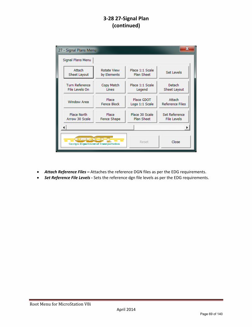
3‐28 27‐Signal Plan
Attach Sheet Layout – Attaches the SheetLayout.dgn file.
Turn Reference File Levels On – Turns on the SheetLayout DGN reference file levels ONLY.
Window Area – Window area to the appropriate area to place the new plan sheet cell.
Place North Arrow 30 Scale – Places the “NARROW” cell from the GDOT‐GN‐SHEETS cell library at a default scale of 30. User may over‐ride the default scale after the command has been selected by keying in “AS=50” etc… before pressing the Data Button.
Rotate View by Elements – User will enter a Data button on the top line of the clip border for the appropriate sheet to be created.
Copy Match Lines – Allows user to copy the match lines from the SheetLayout DGN reference file into the plan sheet file.
Place Fence Block / Place Fence Shape – Use to place a Fence Shape or Block to be used for Clipping the reference files.
Place 1:1 Scale Plan Sheet – Places the “GPLN” cell from the GDOT‐GN‐SHEETS cell library at a default scale of 1.
Place 1:1 Scale Legend ‐ Place legend cell at a scale of 1.
Place GDOT Logo 1:1 Scale – Places the “GLOGO” cell from the GDOT‐GN‐SHEETS cell library at a scale of 1.
Place 30 Scale Plan Sheet – Places the “GPLN” cell from the GDOT‐GN‐SHEETS cell library at a default scale of 30. User may over‐ride the default scale after the command has been selected by keying in “AS=50” etc… before pressing the Data Button.
Set Levels – Sets the sheet DGN file levels and the reference file levels as per the EDG requirements.
Detach Sheet Layout – Detaches the SheetLayout.DGN reference file.
Page 68 of 140
RootMenuforMicroStationV8i April 2014
3‐28 27‐Signal Plan (continued)
Attach Reference Files – Attaches the reference DGN files as per the EDG requirements.
Set Reference File Levels ‐ Sets the reference dgn file levels as per the EDG requirements.
Page 69 of 140

RootMenuforMicroStationV8i April 2014
3‐28 27‐Signal Plan (continued)
Clip Boundary ‐ Clips reference dgn files.
File Design ‐ Saves the current view settings.
Place 30 Scale Bar – Places the “30SC” cell from the GDOT‐GN‐SHEETS cell library.
Place Match Line Text 30 Scale – Places match line text for use at either end of the plan sheet coverage limits at a default scale of 30.
Place GDOT Logo 30 Scale – Places the “GLOGO” cell from the GDOT‐GN‐SHEETS cell library at a scale of 30.
Enter Data Fields – Use to fill in the data fields on the Plan Sheet cell. This command will not be disabled after use, allowing the user to use this command as needed without have to use the “Reset” button.
Turn off Enter Data Fields – Turns off the Data Fields for View 1.
File Design – Saves the current view settings.
Save Plotting View – Saves the plotting view from View 1 for use by the GPlot Utility.
Reset – Enables any disabled commands to allow those commands to be accessed multiple times.
Close – Closes the “27 – Signal Plans Menu” and returns the user to the “Root Menu”.
Page 70 of 140
RootMenuforMicroStationV8i April 2014
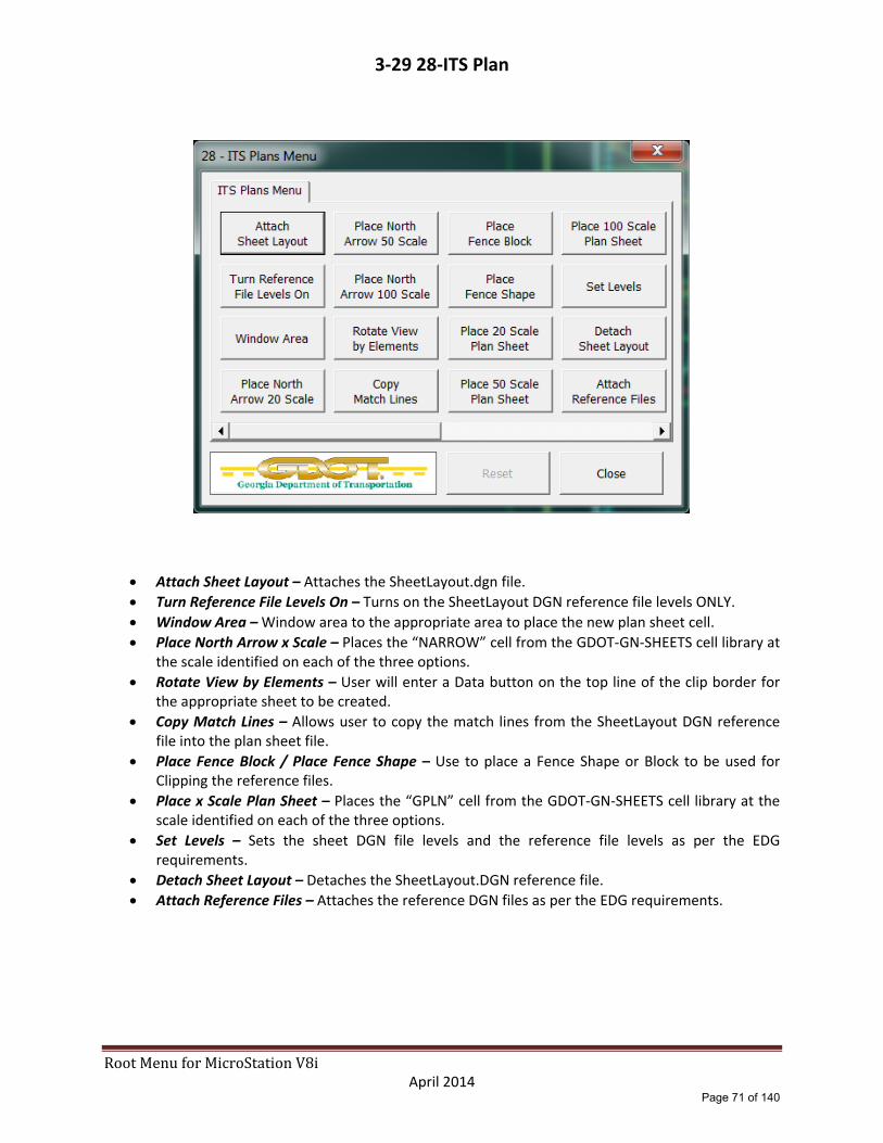
3‐29 28‐ITS Plan
Attach Sheet Layout – Attaches the SheetLayout.dgn file.
Turn Reference File Levels On – Turns on the SheetLayout DGN reference file levels ONLY.
Window Area – Window area to the appropriate area to place the new plan sheet cell.
Place North Arrow x Scale – Places the “NARROW” cell from the GDOT‐GN‐SHEETS cell library at the scale identified on each of the three options.
Rotate View by Elements – User will enter a Data button on the top line of the clip border for the appropriate sheet to be created.
Copy Match Lines – Allows user to copy the match lines from the SheetLayout DGN reference file into the plan sheet file.
Place Fence Block / Place Fence Shape – Use to place a Fence Shape or Block to be used for Clipping the reference files.
Place x Scale Plan Sheet – Places the “GPLN” cell from the GDOT‐GN‐SHEETS cell library at the scale identified on each of the three options.
Set Levels – Sets the sheet DGN file levels and the reference file levels as per the EDG requirements.
Detach Sheet Layout – Detaches the SheetLayout.DGN reference file.
Attach Reference Files – Attaches the reference DGN files as per the EDG requirements.
Page 71 of 140

RootMenuforMicroStationV8i April 2014
3‐29 28‐ITS Plan (continued)
Set Reference File Levels – Sets the reference dgn file levels as per the EDG requirements.
Clip Boundary ‐ Clips reference dgn files.
File Design – Saves the current view settings.
Place x Scale Bar Cell – Places the scale bar cell at a scale of 20, 50 or 100.
Place Match Line Text x Scale – Places match line text for use at either end of the plan sheet coverage limits at a scale of 20, 50 or 100.
Place GDOT Logo x Scale – Places the “GLOGO” cell from the GDOT‐GN‐SHEETS cell library at a scale of 20, 50 or 100.
Enter Data Fields – Use to fill in the data fields on the Plan Sheet cell. This command will not be disabled after use, allowing the user to use this command as needed without have to use the “Reset” button.
Turn off Enter Data Fields – Turns off the Data Fields for View 1.
File Design – Saves the current view settings.
Save Plotting View – Saves the plotting view from View 1 for use by the GPlot Utility.
Reset – Enables any disabled commands to allow those commands to be accessed multiple times.
Close – Closes the “28 – ITS Plans Menu” and returns the user to the “Root Menu”.
Page 72 of 140

RootMenuforMicroStationV8i April 2014
3‐30 29‐Landscaping Plan
Attach Sheet Layout – Attaches the SheetLayout.dgn file.
Turn Reference File Levels On – Turns on the SheetLayout DGN reference file levels ONLY.
Window Area – Window area to the appropriate area to place the new plan sheet cell.
Place North Arrow x Scale – Places the “NARROW” cell from the GDOT‐GN‐SHEETS cell library at the scale identified on each of the three options.
Rotate View by Elements – User will enter a Data button on the top line of the clip border for the appropriate sheet to be created.
Copy Match Lines – Allows user to copy the match lines from the SheetLayout DGN reference file into the plan sheet file.
Place Fence Block / Place Fence Shape – Use to place a Fence Shape or Block to be used for Clipping the reference files.
Place x Scale Plan Sheet – Places the “GPLN” cell from the GDOT‐GN‐SHEETS cell library at the scale identified on each of the three options.
Set Levels – Sets the sheet DGN file levels and the reference file levels as per the EDG requirements.
Detach Sheet Layout – Detaches the SheetLayout.DGN reference file.
Attach Reference Files – Attaches the reference DGN files as per the EDG requirements.
Page 73 of 140

RootMenuforMicroStationV8i April 2014
3‐30 29‐Landscaping Plan (continued)
Set Reference File Levels – Sets the reference dgn file levels as per the EDG requirements.
Clip Boundary ‐ Clips reference dgn files.
File Design – Saves the current view settings.
Place x Scale Bar Cell – Places the scale bar cell at a scale of 20, 50 or 100.
Place Match Line Text x Scale – Places match line text for use at either end of the plan sheet coverage limits at a scale of 20, 50 or 100.
Place GDOT Logo x Scale – Places the “GLOGO” cell from the GDOT‐GN‐SHEETS cell library at a scale of 20, 50 or 100.
Enter Data Fields – Use to fill in the data fields on the Plan Sheet cell. This command will not be disabled after use, allowing the user to use this command as needed without have to use the “Reset” button.
Turn off Enter Data Fields – Turns off the Data Fields for View 1.
File Design – Saves the current view settings.
Save Plotting View – Saves the plotting view from View 1 for use by the GPlot Utility.
Reset – Enables any disabled commands to allow those commands to be accessed multiple times.
Close – Closes the “29 – Landscaping Plans Menu” and returns the user to the “Root Menu”.
Page 74 of 140

RootMenuforMicroStationV8i April 2014
3‐31 30‐Mitigation Plan
Attach Sheet Layout – Attaches the SheetLayout.dgn file.
Turn Reference File Levels On – Turns on the SheetLayout DGN reference file levels ONLY.
Window Area – Window area to the appropriate area to place the new plan sheet cell.
Place North Arrow x Scale – Places the “NARROW” cell from the GDOT‐GN‐SHEETS cell library at the scale identified on each of the three options.
Rotate View by Elements – User will enter a Data button on the top line of the clip border for the appropriate sheet to be created.
Copy Match Lines – Allows user to copy the match lines from the SheetLayout DGN reference file into the plan sheet file.
Place Fence Block / Place Fence Shape – Use to place a Fence Shape or Block to be used for Clipping the reference files.
Place x Scale Plan Sheet – Places the “GPLN” cell from the GDOT‐GN‐SHEETS cell library at the scale identified on each of the three options.
Set Levels – Sets the sheet DGN file levels and the reference file levels as per the EDG requirements.
Detach Sheet Layout – Detaches the SheetLayout.DGN reference file.
Attach Reference Files – Attaches the reference DGN files as per the EDG requirements.
Page 75 of 140

RootMenuforMicroStationV8i April 2014
3‐31 30‐Mitigation Plan (continued)
Set Reference File Levels – Sets the reference dgn file levels as per the EDG requirements.
Clip Boundary ‐ Clips reference dgn files.
File Design – Saves the current view settings.
Place x Scale Bar Cell – Places the scale bar cell at a scale of 20, 50 or 100.
Place Match Line Text x Scale – Places match line text for use at either end of the plan sheet coverage limits at a scale of 20, 50 or 100.
Place GDOT Logo x Scale – Places the “GLOGO” cell from the GDOT‐GN‐SHEETS cell library at a scale of 20, 50 or 100.
Enter Data Fields – Use to fill in the data fields on the Plan Sheet cell. This command will not be disabled after use, allowing the user to use this command as needed without have to use the “Reset” button.
Turn off Enter Data Fields – Turns off the Data Fields for View 1.
File Design – Saves the current view settings.
Save Plotting View – Saves the plotting view from View 1 for use by the GPlot Utility.
Reset – Enables any disabled commands to allow those commands to be accessed multiple times.
Close – Closes the “30 – Mitigation Plans Menu” and returns the user to the “Root Menu”.
Page 76 of 140

RootMenuforMicroStationV8i April 2014
3‐32 31‐Retaining Wall Envelopes
Attach Sheet Layout – Attaches the SheetLayout.dgn file.
Turn Reference File Levels On – Turns on the SheetLayout DGN reference file levels ONLY.
Window Area – Window area to the appropriate area to place the new plan sheet cell.
Place North Arrow x Scale – Places the “NARROW” cell from the GDOT‐GN‐SHEETS cell library at the scale identified on each of the three options.
Rotate View by Elements – User will enter a Data button on the top line of the clip border for the appropriate sheet to be created.
Copy Match Lines – Allows user to copy the match lines from the SheetLayout DGN reference file into the plan sheet file.
Place Fence Block / Place Fence Shape – Use to place a Fence Shape or Block to be used for Clipping the reference files.
Place x Scale Plan Sheet – Places the “GPLN” cell from the GDOT‐GN‐SHEETS cell library at the scale identified on each of the three options.
Set Levels – Sets the sheet DGN file levels and the reference file levels as per the EDG requirements.
Detach Sheet Layout – Detaches the SheetLayout.DGN reference file.
Attach Reference Files – Attaches the reference DGN files as per the EDG requirements.
Page 77 of 140
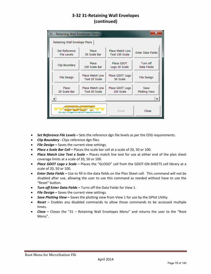
RootMenuforMicroStationV8i April 2014
3‐32 31‐Retaining Wall Envelopes (continued)
Set Reference File Levels – Sets the reference dgn file levels as per the EDG requirements.
Clip Boundary ‐ Clips reference dgn files.
File Design – Saves the current view settings.
Place x Scale Bar Cell – Places the scale bar cell at a scale of 20, 50 or 100.
Place Match Line Text x Scale – Places match line text for use at either end of the plan sheet coverage limits at a scale of 20, 50 or 100.
Place GDOT Logo x Scale – Places the “GLOGO” cell from the GDOT‐GN‐SHEETS cell library at a scale of 20, 50 or 100.
Enter Data Fields – Use to fill in the data fields on the Plan Sheet cell. This command will not be disabled after use, allowing the user to use this command as needed without have to use the “Reset” button.
Turn off Enter Data Fields – Turns off the Data Fields for View 1.
File Design – Saves the current view settings.
Save Plotting View – Saves the plotting view from View 1 for use by the GPlot Utility.
Reset – Enables any disabled commands to allow those commands to be accessed multiple times.
Close – Closes the “31 – Retaining Wall Envelopes Menu” and returns the user to the “Root Menu”.
Page 78 of 140

RootMenuforMicroStationV8i April 2014
3‐33 32‐Retaining Wall Plan
Attach Sheet Layout – Attaches the SheetLayout.dgn file.
Turn Reference File Levels On – Turns on the SheetLayout DGN reference file levels ONLY.
Window Area – Window area to the appropriate area to place the new plan sheet cell.
Place North Arrow x Scale – Places the “NARROW” cell from the GDOT‐GN‐SHEETS cell library at the scale identified on each of the three options.
Rotate View by Elements – User will enter a Data button on the top line of the clip border for the appropriate sheet to be created.
Copy Match Lines – Allows user to copy the match lines from the SheetLayout DGN reference file into the plan sheet file.
Place Fence Block / Place Fence Shape – Use to place a Fence Shape or Block to be used for Clipping the reference files.
Place x Scale Plan Sheet – Places the “GPLN” cell from the GDOT‐GN‐SHEETS cell library at the scale identified on each of the three options.
Set Levels – Sets the sheet DGN file levels and the reference file levels as per the EDG requirements.
Detach Sheet Layout – Detaches the SheetLayout.DGN reference file.
Attach Reference Files – Attaches the reference DGN files as per the EDG requirements.
Page 79 of 140

RootMenuforMicroStationV8i April 2014
3‐33 32‐Retaining Wall Plan (continued)
Set Reference File Levels – Sets the reference dgn file levels as per the EDG requirements.
Clip Boundary ‐ Clips reference dgn files.
File Design – Saves the current view settings.
Place x Scale Bar Cell – Places the scale bar cell at a scale of 20, 50 or 100.
Place Match Line Text x Scale – Places match line text for use at either end of the plan sheet coverage limits at a scale of 20, 50 or 100.
Place GDOT Logo x Scale – Places the “GLOGO” cell from the GDOT‐GN‐SHEETS cell library at a scale of 20, 50 or 100.
Enter Data Fields – Use to fill in the data fields on the Plan Sheet cell. This command will not be disabled after use, allowing the user to use this command as needed without have to use the “Reset” button.
Turn off Enter Data Fields – Turns off the Data Fields for View 1.
File Design – Saves the current view settings.
Save Plotting View – Saves the plotting view from View 1 for use by the GPlot Utility.
Reset – Enables any disabled commands to allow those commands to be accessed multiple times.
Close – Closes the “32 – Retaining Wall Plans Menu” and returns the user to the “Root Menu”.
Page 80 of 140

RootMenuforMicroStationV8i April 2014
3‐34 33‐Sound Barrier Envelopes
Attach Sheet Layout – Attaches the SheetLayout.dgn file.
Turn Reference File Levels On – Turns on the SheetLayout DGN reference file levels ONLY.
Window Area – Window area to the appropriate area to place the new plan sheet cell.
Place North Arrow x Scale – Places the “NARROW” cell from the GDOT‐GN‐SHEETS cell library at the scale identified on each of the three options.
Rotate View by Elements – User will enter a Data button on the top line of the clip border for the appropriate sheet to be created.
Copy Match Lines – Allows user to copy the match lines from the SheetLayout DGN reference file into the plan sheet file.
Place Fence Block / Place Fence Shape – Use to place a Fence Shape or Block to be used for Clipping the reference files.
Place x Scale Plan Sheet – Places the “GPLN” cell from the GDOT‐GN‐SHEETS cell library at the scale identified on each of the three options.
Set Levels – Sets the sheet DGN file levels and the reference file levels as per the EDG requirements.
Detach Sheet Layout – Detaches the SheetLayout.DGN reference file.
Attach Reference Files – Attaches the reference DGN files as per the EDG requirements.
Page 81 of 140

RootMenuforMicroStationV8i April 2014
3‐34 33‐Sound Barrier Envelopes (continued)
Set Reference File Levels – Sets the reference dgn file levels as per the EDG requirements.
Clip Boundary ‐ Clips reference dgn files.
File Design – Saves the current view settings.
Place x Scale Bar Cell – Places the scale bar cell at a scale of 20, 50 or 100.
Place Match Line Text x Scale – Places match line text for use at either end of the plan sheet coverage limits at a scale of 20, 50 or 100.
Place GDOT Logo x Scale – Places the “GLOGO” cell from the GDOT‐GN‐SHEETS cell library at a scale of 20, 50 or 100.
Enter Data Fields – Use to fill in the data fields on the Plan Sheet cell. This command will not be disabled after use, allowing the user to use this command as needed without have to use the “Reset” button.
Turn off Enter Data Fields – Turns off the Data Fields for View 1.
File Design – Saves the current view settings.
Save Plotting View – Saves the plotting view from View 1 for use by the GPlot Utility.
Reset – Enables any disabled commands to allow those commands to be accessed multiple times.
Close – Closes the “33 – Sound Barrier Envelopes Menu” and returns the user to the “Root Menu”.
Page 82 of 140

RootMenuforMicroStationV8i April 2014
3‐35 34‐Sound Barrier Plan
Attach Sheet Layout – Attaches the SheetLayout.dgn file.
Turn Reference File Levels On – Turns on the SheetLayout DGN reference file levels ONLY.
Window Area – Window area to the appropriate area to place the new plan sheet cell.
Place North Arrow x Scale – Places the “NARROW” cell from the GDOT‐GN‐SHEETS cell library at the scale identified on each of the three options.
Rotate View by Elements – User will enter a Data button on the top line of the clip border for the appropriate sheet to be created.
Copy Match Lines – Allows user to copy the match lines from the SheetLayout DGN reference file into the plan sheet file.
Place Fence Block / Place Fence Shape – Use to place a Fence Shape or Block to be used for Clipping the reference files.
Place x Scale Plan Sheet – Places the “GPLN” cell from the GDOT‐GN‐SHEETS cell library at the scale identified on each of the three options.
Set Levels – Sets the sheet DGN file levels and the reference file levels as per the EDG requirements.
Detach Sheet Layout – Detaches the SheetLayout.DGN reference file.
Attach Reference Files – Attaches the reference DGN files as per the EDG requirements.
Page 83 of 140

RootMenuforMicroStationV8i April 2014
3‐35 34‐Sound Barrier Plan (continued)
Set Reference File Levels – Sets the reference dgn file levels as per the EDG requirements.
Clip Boundary ‐ Clips reference dgn files.
File Design – Saves the current view settings.
Place x Scale Bar Cell – Places the scale bar cell at a scale of 20, 50 or 100.
Place Match Line Text x Scale – Places match line text for use at either end of the plan sheet coverage limits at a scale of 20, 50 or 100.
Place GDOT Logo x Scale – Places the “GLOGO” cell from the GDOT‐GN‐SHEETS cell library at a scale of 20, 50 or 100.
Enter Data Fields – Use to fill in the data fields on the Plan Sheet cell. This command will not be disabled after use, allowing the user to use this command as needed without have to use the “Reset” button.
Turn off Enter Data Fields – Turns off the Data Fields for View 1.
File Design – Saves the current view settings.
Save Plotting View – Saves the plotting view from View 1 for use by the GPlot Utility.
Reset – Enables any disabled commands to allow those commands to be accessed multiple times.
Close – Closes the “34 – Sound Barrier Plans Menu” and returns the user to the “Root Menu”.
Page 84 of 140
RootMenuforMicroStationV8i April 2014
3‐36 35‐Bridge Plans (To be released at a later date)
Page 85 of 140

RootMenuforMicroStationV8i April 2014
3‐37 36‐Bridge Culvert Plans (To be released at a later date.)
Page 86 of 140

RootMenuforMicroStationV8i April 2014
3‐38 37‐Miscellaneous Structural (To be released at a later date.)
Page 87 of 140

RootMenuforMicroStationV8i April 2014
3‐39 38‐Special Construction Details (To be released at a later date.)
Page 88 of 140

RootMenuforMicroStationV8i April 2014
3‐40 39‐Special Design Box Culverts (To be released at a later date.)
Page 89 of 140
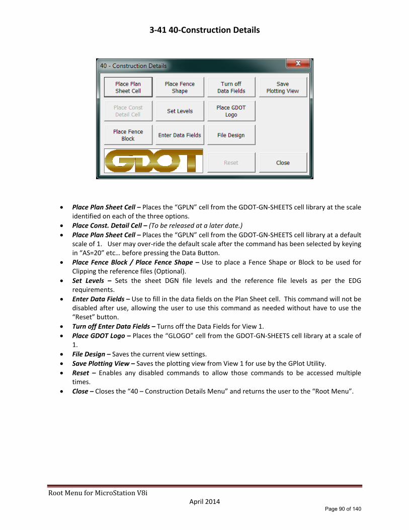
RootMenuforMicroStationV8i April 2014
3‐41 40‐Construction Details
Place Plan Sheet Cell – Places the “GPLN” cell from the GDOT‐GN‐SHEETS cell library at the scale identified on each of the three options.
Place Const. Detail Cell – (To be released at a later date.)
Place Plan Sheet Cell – Places the “GPLN” cell from the GDOT‐GN‐SHEETS cell library at a default scale of 1. User may over‐ride the default scale after the command has been selected by keying in “AS=20” etc… before pressing the Data Button.
Place Fence Block / Place Fence Shape – Use to place a Fence Shape or Block to be used for Clipping the reference files (Optional).
Set Levels – Sets the sheet DGN file levels and the reference file levels as per the EDG requirements.
Enter Data Fields – Use to fill in the data fields on the Plan Sheet cell. This command will not be disabled after use, allowing the user to use this command as needed without have to use the “Reset” button.
Turn off Enter Data Fields – Turns off the Data Fields for View 1.
Place GDOT Logo – Places the “GLOGO” cell from the GDOT‐GN‐SHEETS cell library at a scale of 1.
File Design – Saves the current view settings.
Save Plotting View – Saves the plotting view from View 1 for use by the GPlot Utility.
Reset – Enables any disabled commands to allow those commands to be accessed multiple times.
Close – Closes the “40 – Construction Details Menu” and returns the user to the “Root Menu”.
Page 90 of 140

RootMenuforMicroStationV8i April 2014
3‐42 41‐Georgia Standards
Place Plan Sheet Cell – Places the “GPLN” cell from the GDOT‐GN‐SHEETS cell library at the scale
identified on each of the three options.
Place Ga. Stds Cell – (To be released at a later date.)
Place Plan Sheet Cell – Places the “GPLN” cell from the GDOT‐GN‐SHEETS cell library at a default scale of 1. User may over‐ride the default scale after the command has been selected by keying in “AS=20” etc… before pressing the Data Button.
Place Fence Block / Place Fence Shape – Use to place a Fence Shape or Block to be used for Clipping the reference files (Optional).
Set Levels – Sets the sheet DGN file levels and the reference file levels as per the EDG requirements.
Enter Data Fields – Use to fill in the data fields on the Plan Sheet cell. This command will not be disabled after use, allowing the user to use this command as needed without have to use the “Reset” button.
Turn off Enter Data Fields – Turns off the Data Fields for View 1.
Place GDOT Logo – Places the “GLOGO” cell from the GDOT‐GN‐SHEETS cell library at a scale of 1.
File Design – Saves the current view settings.
Save Plotting View – Saves the plotting view from View 1 for use by the GPlot Utility.
Reset – Enables any disabled commands to allow those commands to be accessed multiple times.
Close – Closes the “41 – Georgia Standards Menu” and returns the user to the “Root Menu”.
Page 91 of 140

RootMenuforMicroStationV8i April 2014
3‐43 44‐Utility Relocation Plan
Attach Sheet Layout – Attaches the SheetLayout.dgn file.
Turn Reference File Levels On – Turns on the SheetLayout DGN reference file levels ONLY.
Window Area – Window area to the appropriate area to place the new plan sheet cell.
Place North Arrow x Scale – Places the “NARROW” cell from the GDOT‐GN‐SHEETS cell library at the scale identified on each of the three options.
Rotate View by Elements – User will enter a Data button on the top line of the clip border for the appropriate sheet to be created.
Copy Match Lines – Allows user to copy the match lines from the SheetLayout DGN reference file into the plan sheet file.
Place Fence Block / Place Fence Shape – Use to place a Fence Shape or Block to be used for Clipping the reference files.
Place x Scale Plan Sheet – Places the “GPLN” cell from the GDOT‐GN‐SHEETS cell library at the scale identified on each of the three options.
Set Levels – Sets the sheet DGN file levels and the reference file levels as per the EDG requirements.
Detach Sheet Layout – Detaches the SheetLayout.DGN reference file.
Attach Reference Files – Attaches the reference DGN files as per the EDG requirements.
Page 92 of 140

RootMenuforMicroStationV8i April 2014
3‐43 44‐Utility Relocation Plan (continued)
Set Reference File Levels – Sets the reference dgn file levels as per the EDG requirements.
Clip Boundary ‐ Clips reference dgn files.
File Design – Saves the current view settings.
Place x Scale Bar Cell – Places the scale bar cell at a scale of 20, 50 or 100.
Place Match Line Text x Scale – Places match line text for use at either end of the plan sheet coverage limits at a scale of 20, 50 or 100.
Place GDOT Logo x Scale – Places the “GLOGO” cell from the GDOT‐GN‐SHEETS cell library at a scale of 20, 50 or 100.
Enter Data Fields – Use to fill in the data fields on the Plan Sheet cell. This command will not be disabled after use, allowing the user to use this command as needed without have to use the “Reset” button.
Turn off Enter Data Fields – Turns off the Data Fields for View 1.
File Design – Saves the current view settings.
Save Plotting View – Saves the plotting view from View 1 for use by the GPlot Utility.
Reset – Enables any disabled commands to allow those commands to be accessed multiple times.
Close – Closes the “44 – Utility Relocation Plans Menu” and returns the user to the “Root Menu”.
Page 93 of 140

RootMenuforMicroStationV8i April 2014
3‐44 50‐Erosion Cover Sheet
Attach Reference Files – Attaches reference files to the Erosion Cover Sheet DGN file as per the EDG requirements.
Place Fence Block / Place Fence Shape – Use to place a Fence Shape or Block to be used for Clipping the reference files.
Clip Boundary – Clips reference dgn files.
File Design ‐ Saves the current view settings.
Place Cover Sheet Cell – Places the “EROCOV” cell from the GDOT‐GN‐SHEETS cell library at a default scale of 500. User may over‐ride the default scale after the command has been selected by keying in “AS=1000” etc… before pressing the Data Button.
Set Levels – Sets the cover sheet DGN file levels and all reference file levels as per the EDG requirements.
Place North 500 Arrow – Places the “COVNOR” cell from the GDOT‐GN‐SHEETS cell library at a default scale of 500. User may over‐ride the default scale after the command has been selected by keying in “AS=1000” etc… before pressing the Data Button.
Place 500 Scale Bar – Places the “500SC” cell from the GDOT‐GN‐SHEETS cell library at a scale of 500.
Place GDOT Logo 500 Scale – Places the “GLOGO” cell from the GDOT‐GN‐SHEETS cell library at a scale of 500.
Enter Data Fields – Use to fill in the data fields on the Cover Sheet cell. This command will not be disabled after use, allowing the user to use this command as needed without have to use the “Reset” button.
Turn off Enter Data Fields – Turns off the Data Fields for View 1.
File Design – Saves the current view settings.
Save Plotting View – Saves the plotting view from View 1 for use by the GPlot Utility.
Reset – Enables any disabled commands to allow those commands to be accessed multiple times.
Close – Closes the “50 – Erosion Cover Sheet Menu” and returns the user to the “Root Menu”.
Page 94 of 140

RootMenuforMicroStationV8i April 2014
3‐45 51‐ESPCP General Notes
Place Plan Sheet Cell – Places the “GPLN” cell from the GDOT‐GN‐SHEETS cell library at a default scale of 1.
Set Levels – Sets the sheet DGN file levels as per the EDG requirements.
Place GDOT Logo – Places the “GLOGO” cell from the GDOT‐GN‐SHEETS cell library at a scale of 1.
Enter Data Fields – Use to fill in the data fields on the Plan Sheet cell. This command will not be disabled after use, allowing the user to use this command as needed without have to use the “Reset” button.
Turn off Enter Data Fields – Turns off the Data Fields for View 1.
File Design – Saves the current view settings.
Save Plotting View – Saves the plotting view from View 1 for use by the GPlot Utility.
Remaining 4 buttons – Place cells as described on each button.
Reset – Enables any disabled commands to allow those commands to be accessed multiple times.
Close – Closes the “51 – ESPCP General Notes” menu and returns the user to the “Root Menu”.
Page 95 of 140

RootMenuforMicroStationV8i April 2014
3‐46 52‐Erosion Control Legend (To be released at a later date.)
Page 96 of 140
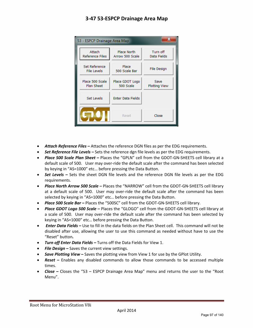
RootMenuforMicroStationV8i April 2014
3‐47 53‐ESPCP Drainage Area Map
Attach Reference Files – Attaches the reference DGN files as per the EDG requirements.
Set Reference File Levels – Sets the reference dgn file levels as per the EDG requirements.
Place 500 Scale Plan Sheet – Places the “GPLN” cell from the GDOT‐GN‐SHEETS cell library at a default scale of 500. User may over‐ride the default scale after the command has been selected by keying in “AS=1000” etc… before pressing the Data Button.
Set Levels – Sets the sheet DGN file levels and the reference DGN file levels as per the EDG requirements.
Place North Arrow 500 Scale – Places the “NARROW” cell from the GDOT‐GN‐SHEETS cell library at a default scale of 500. User may over‐ride the default scale after the command has been selected by keying in “AS=1000” etc… before pressing the Data Button.
Place 500 Scale Bar – Places the “500SC” cell from the GDOT‐GN‐SHEETS cell library.
Place GDOT Logo 500 Scale – Places the “GLOGO” cell from the GDOT‐GN‐SHEETS cell library at a scale of 500. User may over‐ride the default scale after the command has been selected by keying in “AS=1000” etc… before pressing the Data Button.
Enter Data Fields – Use to fill in the data fields on the Plan Sheet cell. This command will not be disabled after use, allowing the user to use this command as needed without have to use the “Reset” button.
Turn off Enter Data Fields – Turns off the Data Fields for View 1.
File Design – Saves the current view settings.
Save Plotting View – Saves the plotting view from View 1 for use by the GPlot Utility.
Reset – Enables any disabled commands to allow those commands to be accessed multiple times.
Close – Closes the “53 – ESPCP Drainage Area Map” menu and returns the user to the “Root Menu”.
Page 97 of 140

RootMenuforMicroStationV8i April 2014
3‐48 54‐BMP Location Details
“BMP Location Details (1)”
Attach Sheet Layout – Attaches the SheetLayout.dgn file.
Turn Reference File Levels On – Turns on the SheetLayout DGN reference file levels ONLY.
Window Area – Window area to the appropriate area to place the new plan sheet cell.
Place North Arrow x Scale – Places the “NARROW” cell from the GDOT‐GN‐SHEETS cell library at the scale identified on each of the three options.
Rotate View by Elements – User will enter a Data button on the top line of the clip border for the appropriate sheet to be created.
Copy Match Lines – Allows user to copy the match lines from the SheetLayout DGN reference file into the plan sheet file.
Place Fence Block / Place Fence Shape – Use to place a Fence Shape or Block to be used for Clipping the reference files.
Place x Scale Plan Sheet – Places the “GPLN” cell from the GDOT‐GN‐SHEETS cell library at the scale identified on each of the three options.
Set Levels – Sets the sheet DGN file levels and the reference file levels as per the EDG requirements.
Detach Sheet Layout – Detaches the SheetLayout.DGN reference file.
Attach Reference Files – Attaches the reference DGN files as per the EDG requirements.
Page 98 of 140

RootMenuforMicroStationV8i April 2014
3‐48 54‐BMP Location Details (continued)
“BMP Location Details (1)”
Set Reference File Levels – Sets the reference dgn file levels as per the EDG requirements.
Clip Boundary ‐ Clips reference dgn files.
File Design – Saves the current view settings.
Place x Scale Bar Cell – Places the scale bar cell at a scale of 20, 50 or 100.
Place GDOT Logo x Scale – Places the “GLOGO” cell from the GDOT‐GN‐SHEETS cell library at a scale of 20, 50 or 100.
Place Match Line Text x Scale – Places match line text for use at either end of the plan sheet coverage limits at a scale of 20, 50 or 100.
Enter Data Fields – Use to fill in the data fields on the Plan Sheet cell. This command will not be disabled after use, allowing the user to use this command as needed without have to use the “Reset” button.
Turn off Enter Data Fields – Turns off the Data Fields for View 1.
File Design – Saves the current view settings.
Save Plotting View – Saves the plotting view from View 1 for use by the GPlot Utility.
Reset – Enables any disabled commands to allow those commands to be accessed multiple times.
Close – Closes the “54 – BMP Location Details (1)” menu and returns the user to the “Root Menu”.
Use 54 – BMP Location Details (1) guidelines for menus 54 – BMP Location Details (2) through
54 – BMP Location Details (5).
Page 99 of 140
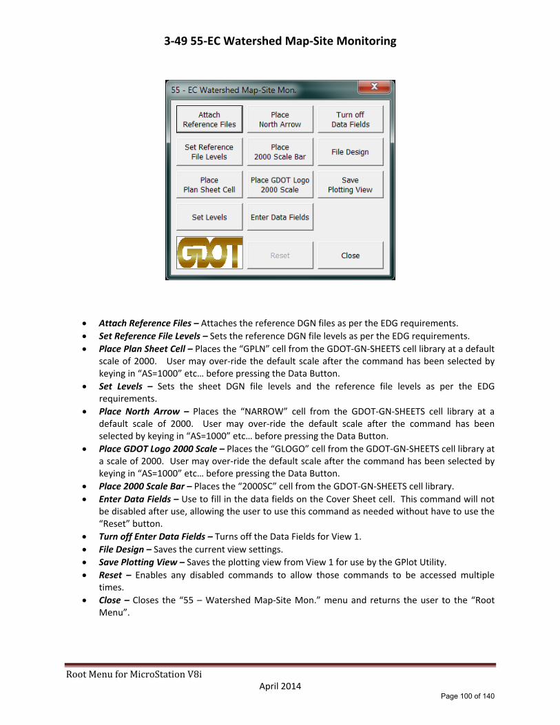
RootMenuforMicroStationV8i April 2014
3‐49 55‐EC Watershed Map‐Site Monitoring
Attach Reference Files – Attaches the reference DGN files as per the EDG requirements.
Set Reference File Levels – Sets the reference DGN file levels as per the EDG requirements.
Place Plan Sheet Cell – Places the “GPLN” cell from the GDOT‐GN‐SHEETS cell library at a default scale of 2000. User may over‐ride the default scale after the command has been selected by keying in “AS=1000” etc… before pressing the Data Button.
Set Levels – Sets the sheet DGN file levels and the reference file levels as per the EDG requirements.
Place North Arrow – Places the “NARROW” cell from the GDOT‐GN‐SHEETS cell library at a default scale of 2000. User may over‐ride the default scale after the command has been selected by keying in “AS=1000” etc… before pressing the Data Button.
Place GDOT Logo 2000 Scale – Places the “GLOGO” cell from the GDOT‐GN‐SHEETS cell library at a scale of 2000. User may over‐ride the default scale after the command has been selected by keying in “AS=1000” etc… before pressing the Data Button.
Place 2000 Scale Bar – Places the “2000SC” cell from the GDOT‐GN‐SHEETS cell library.
Enter Data Fields – Use to fill in the data fields on the Cover Sheet cell. This command will not be disabled after use, allowing the user to use this command as needed without have to use the “Reset” button.
Turn off Enter Data Fields – Turns off the Data Fields for View 1.
File Design – Saves the current view settings.
Save Plotting View – Saves the plotting view from View 1 for use by the GPlot Utility.
Reset – Enables any disabled commands to allow those commands to be accessed multiple times.
Close – Closes the “55 – Watershed Map‐Site Mon.” menu and returns the user to the “Root Menu”.
Page 100 of 140
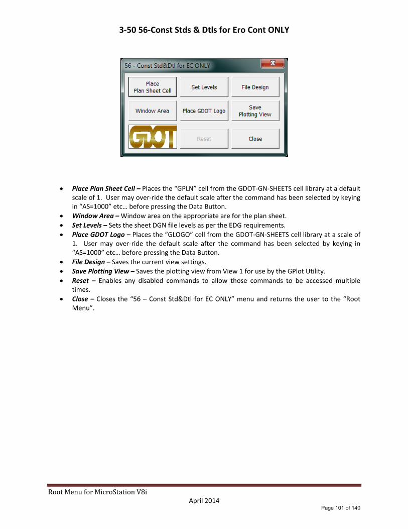
RootMenuforMicroStationV8i April 2014
3‐50 56‐Const Stds & Dtls for Ero Cont ONLY
Place Plan Sheet Cell – Places the “GPLN” cell from the GDOT‐GN‐SHEETS cell library at a default scale of 1. User may over‐ride the default scale after the command has been selected by keying in “AS=1000” etc… before pressing the Data Button.
Window Area – Window area on the appropriate are for the plan sheet.
Set Levels – Sets the sheet DGN file levels as per the EDG requirements.
Place GDOT Logo – Places the “GLOGO” cell from the GDOT‐GN‐SHEETS cell library at a scale of 1. User may over‐ride the default scale after the command has been selected by keying in “AS=1000” etc… before pressing the Data Button.
File Design – Saves the current view settings.
Save Plotting View – Saves the plotting view from View 1 for use by the GPlot Utility.
Reset – Enables any disabled commands to allow those commands to be accessed multiple times.
Close – Closes the “56 – Const Std&Dtl for EC ONLY” menu and returns the user to the “Root Menu”.
Page 101 of 140

RootMenuforMicroStationV8i April 2014
3‐51 60‐Right of Way Plan‐Cover
Attach Reference Files – Attaches reference files to the Right of Way Cover Sheet DGN file as per the EDG requirements.
Place Fence Block / Place Fence Shape – Use to place a Fence Shape or Block to be used for Clipping the reference files.
Clip Boundary – Clips reference dgn files.
File Design ‐ Saves the current view settings.
Place Cover Sheet Cell – Places the “GRWCOV” cell from the GDOT‐GN‐SHEETS cell library at a default scale of 500. User may over‐ride the default scale after the command has been selected by keying in “AS=1000” etc… before pressing the Data Button.
Set Levels – Sets the cover sheet DGN file levels and all reference file levels as per the EDG requirements.
Place North 500 Arrow – Places the “COVNOR” cell from the GDOT‐GN‐SHEETS cell library at a default scale of 500. User may over‐ride the default scale after the command has been selected by keying in “AS=1000” etc… before pressing the Data Button.
Place 500 Scale Bar – Places the “500SC” cell from the GDOT‐GN‐SHEETS cell library at a scale of 500.
Enter Data Fields – Use to fill in the data fields on the Cover Sheet cell. This command will not be disabled after use, allowing the user to use this command as needed without have to use the “Reset” button.
Turn off Enter Data Fields – Turns off the Data Fields for View 1.
File Design – Saves the current view settings.
Save Plotting View – Saves the plotting view from View 1 for use by the GPlot Utility.
Reset – Enables any disabled commands to allow those commands to be accessed multiple times.
Close – Closes the “60 – Right of Way Plans ‐ Cover” menu and returns the user to the “Root Menu”.
Page 102 of 140
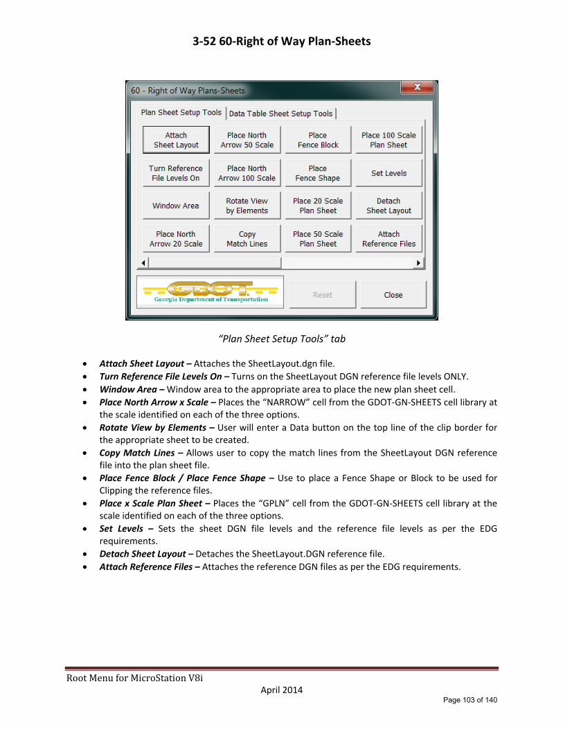
RootMenuforMicroStationV8i April 2014
3‐52 60‐Right of Way Plan‐Sheets
“Plan Sheet Setup Tools” tab
Attach Sheet Layout – Attaches the SheetLayout.dgn file.
Turn Reference File Levels On – Turns on the SheetLayout DGN reference file levels ONLY.
Window Area – Window area to the appropriate area to place the new plan sheet cell.
Place North Arrow x Scale – Places the “NARROW” cell from the GDOT‐GN‐SHEETS cell library at the scale identified on each of the three options.
Rotate View by Elements – User will enter a Data button on the top line of the clip border for the appropriate sheet to be created.
Copy Match Lines – Allows user to copy the match lines from the SheetLayout DGN reference file into the plan sheet file.
Place Fence Block / Place Fence Shape – Use to place a Fence Shape or Block to be used for Clipping the reference files.
Place x Scale Plan Sheet – Places the “GPLN” cell from the GDOT‐GN‐SHEETS cell library at the scale identified on each of the three options.
Set Levels – Sets the sheet DGN file levels and the reference file levels as per the EDG requirements.
Detach Sheet Layout – Detaches the SheetLayout.DGN reference file.
Attach Reference Files – Attaches the reference DGN files as per the EDG requirements.
Page 103 of 140

RootMenuforMicroStationV8i April 2014
3‐52 60‐Right of Way Plan‐Sheets (continued)
“Plan Sheet Setup Tools” tab
Set Reference File Levels – Sets the reference dgn file levels as per the EDG requirements.
Clip Boundary ‐ Clips reference dgn files.
File Design – Saves the current view settings.
Place x Scale Bar Cell – Places the scale bar cell at a scale of 20, 50 or 100.
Place Match Line Text x Scale – Places match line text for use at either end of the plan sheet coverage limits at a scale of 20, 50 or 100.
Place GDOT Logo x Scale – Places the “GLOGO” cell from the GDOT‐GN‐SHEETS cell library at a scale of 20, 50 or 100.
Enter Data Fields – Use to fill in the data fields on the Plan Sheet cell. This command will not be disabled after use, allowing the user to use this command as needed without have to use the “Reset” button.
Turn off Enter Data Fields – Turns off the Data Fields for View 1.
File Design – Saves the current view settings.
Save Plotting View – Saves the plotting view from View 1 for use by the GPlot Utility.
Reset – Enables any disabled commands to allow those commands to be accessed multiple times.
Close – Closes the “60 – Right of Way Plans‐Sheets” menu and returns the user to the “Root Menu”.
Page 104 of 140

RootMenuforMicroStationV8i April 2014
3‐52 60‐Right of Way Plan‐Sheets (continued)
“Data Table Sheet Setup Tools” tab
Place 20 Scale Plan Sheet – Place the “GPLN” cell from the GDOT‐GN‐SHEETS cell library at 20 scale.
Place 50 Scale Plan Sheet ‐ Place the “GPLN” cell from the GDOT‐GN‐SHEETS cell library at 50 scale.
Place 100 Scale Plan Sheet ‐ Place the “GPLN” cell from the GDOT‐GN‐SHEETS cell library at 100 scale.
Place GDOT Logo x Scale – Places the “GLOGO” cell from the GDOT‐GN‐SHEETS cell library at a scale of 20, 50 or 100.
Set Levels – Sets the sheet DGN file levels as per the EDG requirements.
Enter Data Fields – Use to fill in the data fields on the Plan Sheet cell. This command will not be disabled after use, allowing the user to use this command as needed without have to use the “Reset” button.
Turn off Enter Data Fields – Turns off the Data Fields for View 1.
File Design – Saves the current view settings.
Save Plotting View – Saves the plotting view from View 1 for use by the GPlot Utility.
Include Data Table 20 Scale through Include Data Table 100 Scale‐ Imports an ASCII text file to fill in the required data table information at 20, 50 or 100 scale. This file must be in the correct format. An example text file is included in the CADAll download.
Reset – Enables any disabled commands to allow those commands to be accessed multiple times.
Close – Closes the “60 – Right of Way Plans‐Sheets” menu and returns the user to the “Root Menu”.
Page 105 of 140

4-1 Reference File - Expanded
The following sections provide an expanded description of the functions of the GDOT Root Menu Reference File section that is included in the GDOT Workspace for MicroStation V8i.
Page 106 of 140

RootMenuforMicroStationV8i April 2014
4‐2 Sheet Layout Tools
Fit View – MicroStation “Fit View” command.
Window Area – MicroStation “Window Area” command.
Match Lines – Use to draw plan sheet Match Lines.
Rotate View – MicroStation “Rotate View by 2pts” command.
Clip 20 Scale – Places the “SCLIP” cell from the GDOT‐GN‐SHEETS cell library at 20 scale.
Clip 50 Scale – Places the “SCLIP” cell from the GDOT‐GN‐SHEETS cell library at 50 scale.
Pan View – MicroStation “Window Pan” command.
Fit Sheets – MicroStation “Fit View” command.
1st Sht Number – Enter in text of first sheet number.
Number Sheets – MicroStation “Copy and Increment Text” command based on the 1st Sht Number entry.
Close – Closes the “Sheet Layout Tools” menu and returns the user to the “Root Menu”.
Page 107 of 140

RootMenuforMicroStationV8i April 2014
4‐3 [MAIN] Alignment/EOP
Guardrail Left – Place lines/arcs with the guardrail line patterning for the left side of the roadway.
Guardrail Right – Place lines/arcs with the guardrail line patterning for the right side of the roadway.
Type 12 Left – Places the “TP12” cell from the GDOT‐GN‐Misc‐Roadway cell library for the left side of the roadway.
Type 12 Right ‐ Places the “TP12” cell from the GDOT‐GN‐Misc‐Roadway cell library for the right side of the roadway.
Type 1 – Places the “TP1” cell from the GDOT‐GN‐Misc‐Roadway cell library.
EOP – Places lines/arcs for drawing mainline edge of pavements.
Fence 20 Scale – Place lines/arcs with fencing line patterning at 20 scale.
Fence 50 Scale – Place lines/arcs with fencing line patterning at 50 scale.
Roadway Cells – Opens the GDOT‐GN‐MISC‐Roadway cell library.
Close – Closes the “MAIN DGN File Menu” and returns the user to the “Root Menu”.
Page 108 of 140

RootMenuforMicroStationV8i April 2014
4‐4 [DRNG] Drainage – Plan View
“Drain Pipes/Ditches” tab
18” Drain Pipe through Single Ditch Line – Place lines/arcs with appropriate linear patterning by button description as per the EDG requirements.
Close – Closes the “DRNG DGN File Menu” and returns the user to the “Root Menu”.
Page 109 of 140

RootMenuforMicroStationV8i April 2014
4‐4 [DRNG] Drainage – Plan View
(continued)
“Labels – 20 Scale” tab
18” Left through 72” Right – Place drainage pipe size labels with flow direction arrow at 20 scale.
Close – Closes the “DRNG DGN File Menu” and returns the user to the “Root Menu”.
Page 110 of 140

RootMenuforMicroStationV8i April 2014
4‐4 [DRNG] Drainage – Plan View
(continued)
“Labels – 50 Scale” tab
18” Left through 72” Right – Place drainage pipe size labels with flow direction arrow at 50 scale.
Close – Closes the “DRNG DGN File Menu” and returns the user to the “Root Menu”.
Page 111 of 140

RootMenuforMicroStationV8i April 2014
4‐4 [DRNG] Drainage – Plan View
(continued)
“Structures” tab
AA by 2 Pts – Set the active angle by two user selected points.
101B – HW through D6 – Safety Grate ‐ Place drainage structure cells based on button description.
Close – Closes the “DRNG DGN File Menu” and returns the user to the “Root Menu”.
Page 112 of 140

RootMenuforMicroStationV8i April 2014
4‐5 [REQD] Reqd R/W & Easements
Rqd RW 20 Scale – Place Required Right of Way cells via MicroStation Cell Selector utility at 20 scale.
Rqd RW 50 Scale – Place Required Right of Way cells via MicroStation Cell Selector utility at 50 scale.
Close – Closes the “REQD DGN File Menu” and returns the user to the “Root Menu”.
Page 113 of 140

RootMenuforMicroStationV8i April 2014
4‐6 [SIGN] Signing and Pavement Marking
“20 Scale Cells” tab
(M‐Signs) through D‐Signs ‐ Place signing related cells via MicroStation Cell Selector utility at 20 scale.
Close – Closes the “[SIGN] Dgn” and returns the user to the “Root Menu”.
“50 Scale Cells” tab
(M‐Signs) through D‐Signs ‐ Place signing related cells via MicroStation Cell Selector utility at 50 scale.
Close – Closes the “[SIGN] Dgn” and returns the user to the “Root Menu”.
Page 114 of 140

RootMenuforMicroStationV8i April 2014
4‐7 [SGNL] Signal Plan
935_01 through Signal Cells ‐ Place signal related cells via MicroStation Cell Selector utility at 20 scale.
Close – Closes the “[SGNL] Dgn Reference File” menu and returns the user to the “Root Menu”.
Use 20 Scale guidelines for 30 and 50 scale tabs.
Page 115 of 140
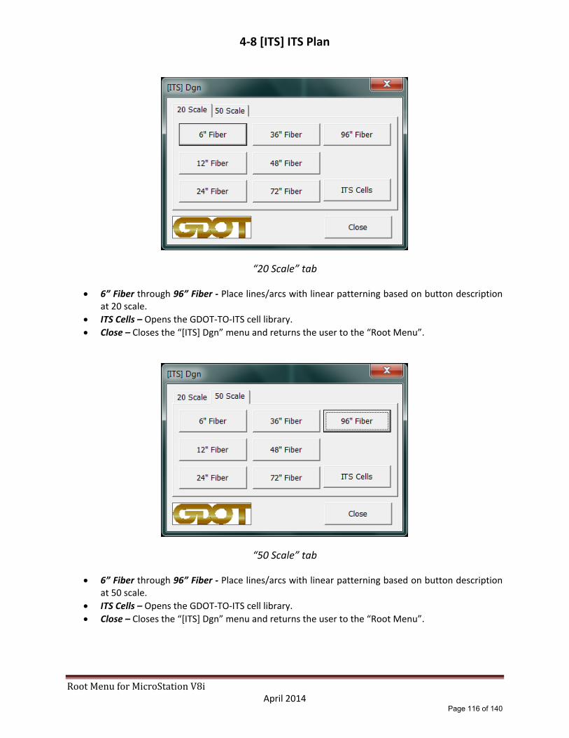
RootMenuforMicroStationV8i April 2014
4‐8 [ITS] ITS Plan
“20 Scale” tab
6” Fiber through 96” Fiber ‐ Place lines/arcs with linear patterning based on button description at 20 scale.
ITS Cells – Opens the GDOT‐TO‐ITS cell library.
Close – Closes the “[ITS] Dgn” menu and returns the user to the “Root Menu”.
“50 Scale” tab
6” Fiber through 96” Fiber ‐ Place lines/arcs with linear patterning based on button description at 50 scale.
ITS Cells – Opens the GDOT‐TO‐ITS cell library.
Close – Closes the “[ITS] Dgn” menu and returns the user to the “Root Menu”.
Page 116 of 140
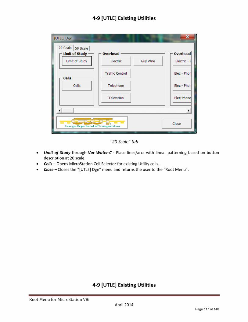
RootMenuforMicroStationV8i April 2014
4‐9 [UTLE] Existing Utilities
“20 Scale” tab
Limit of Study through Var Water‐C ‐ Place lines/arcs with linear patterning based on button description at 20 scale.
Cells – Opens MicroStation Cell Selector for existing Utility cells.
Close – Closes the “[UTLE] Dgn” menu and returns the user to the “Root Menu”.
4‐9 [UTLE] Existing Utilities
Page 117 of 140

RootMenuforMicroStationV8i April 2014
(continued)
“50 Scale” tab
Limit of Study through Var Water‐C ‐ Place lines/arcs with linear patterning based on button description at 50 scale.
Cells – Opens MicroStation Cell Selector for existing Utility cells.
Close – Closes the “[UTLE] Dgn” menu and returns the user to the “Root Menu”.
Page 118 of 140

RootMenuforMicroStationV8i April 2014
4‐10 [UTLP] Proposed Utilities
“20 Scale” tab
Cells – Place existing utility cells via the MicroStation Cell Selector utility at 20 scale.
Electric through Var Water ‐ Place lines/arcs with linear patterning based on button description at 20 scale.
Close – Closes the “[UTLP] Dgn” menu and returns the user to the “Root Menu”.
Page 119 of 140
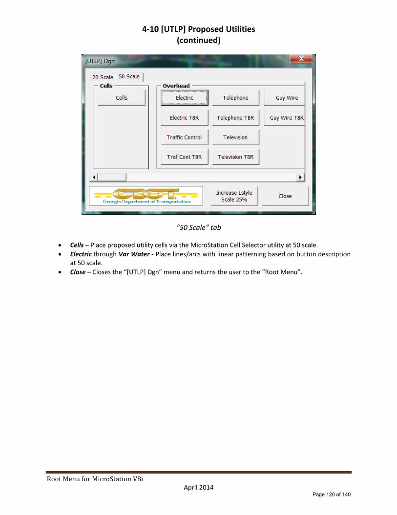
RootMenuforMicroStationV8i April 2014
4‐10 [UTLP] Proposed Utilities (continued)
“50 Scale” tab
Cells – Place proposed utility cells via the MicroStation Cell Selector utility at 50 scale.
Electric through Var Water ‐ Place lines/arcs with linear patterning based on button description at 50 scale.
Close – Closes the “[UTLP] Dgn” menu and returns the user to the “Root Menu”.
Page 120 of 140

RootMenuforMicroStationV8i April 2014
4‐11 [LIMT] Construction Limits
Cut Line ‐ Place lines/arcs with Cut Line construction limit linear patterning.
Fill Line – Place lines/arcs with Fill Line construction limit liner patterning.
Close – Closes the “[LIMT] Dgn” menu and returns the user to the “Root Menu”.
Page 121 of 140
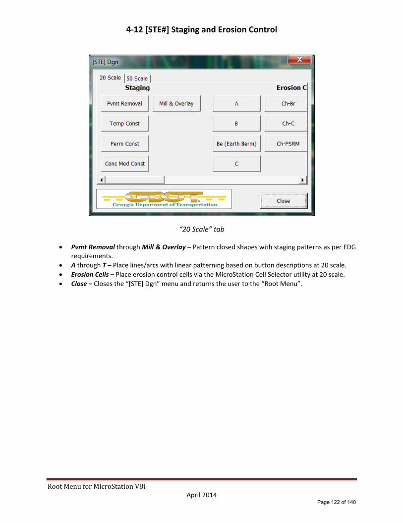
RootMenuforMicroStationV8i April 2014
4‐12 [STE#] Staging and Erosion Control
“20 Scale” tab
Pvmt Removal through Mill & Overlay – Pattern closed shapes with staging patterns as per EDG requirements.
A through T – Place lines/arcs with linear patterning based on button descriptions at 20 scale.
Erosion Cells – Place erosion control cells via the MicroStation Cell Selector utility at 20 scale.
Close – Closes the “[STE] Dgn” menu and returns the user to the “Root Menu”.
Page 122 of 140
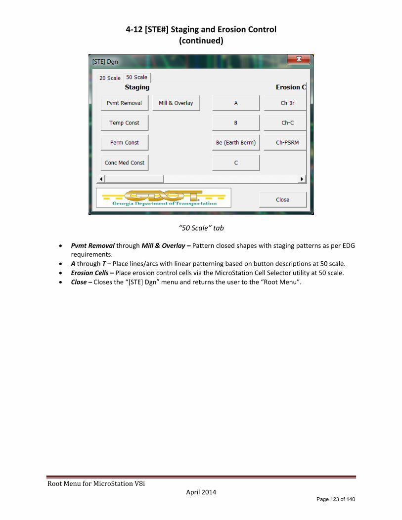
RootMenuforMicroStationV8i April 2014
4‐12 [STE#] Staging and Erosion Control (continued)
“50 Scale” tab
Pvmt Removal through Mill & Overlay – Pattern closed shapes with staging patterns as per EDG requirements.
A through T – Place lines/arcs with linear patterning based on button descriptions at 50 scale.
Erosion Cells – Place erosion control cells via the MicroStation Cell Selector utility at 50 scale.
Close – Closes the “[STE] Dgn” menu and returns the user to the “Root Menu”.
Page 123 of 140

RootMenuforMicroStationV8i April 2014
4‐13 [ENVE] Existing Environmental & Cultural Resources
“20 Scale” tab
Environmental through Wetlands – Place lines/arcs with linear patterning at 20 scale based on EDG requirements.
Use 20 Scale guidelines for 50 scale tab.
Page 124 of 140
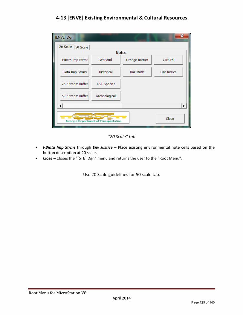
RootMenuforMicroStationV8i April 2014
4‐13 [ENVE] Existing Environmental & Cultural Resources
“20 Scale” tab
I‐Biota Imp Strms through Env Justice – Place existing environmental note cells based on the button description at 20 scale.
Close – Closes the “[STE] Dgn” menu and returns the user to the “Root Menu”.
Use 20 Scale guidelines for 50 scale tab.
Page 125 of 140

RootMenuforMicroStationV8i April 2014
4‐14 [ENVP] Proposed Environmental & Cultural Resources
“20 Scale” tab
Cult Resc through Orange Fence – Place lines/arcs with linear patterning at 20 scale based on EDG requirements.
Close – Closes the “[ENVP] Dgn” menu and returns the user to the “Root Menu”.
Use 20 Scale guidelines for 50 scale tab.
Page 126 of 140
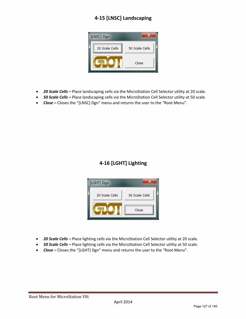
RootMenuforMicroStationV8i April 2014
4‐15 [LNSC] Landscaping
20 Scale Cells – Place landscaping cells via the MicroStation Cell Selector utility at 20 scale.
50 Scale Cells – Place landscaping cells via the MicroStation Cell Selector utility at 50 scale.
Close – Closes the “[LNSC] Dgn” menu and returns the user to the “Root Menu”.
4‐16 [LGHT] Lighting
20 Scale Cells – Place lighting cells via the MicroStation Cell Selector utility at 20 scale.
50 Scale Cells – Place lighting cells via the MicroStation Cell Selector utility at 50 scale.
Close – Closes the “[LGHT] Dgn” menu and returns the user to the “Root Menu”.
Page 127 of 140

RootMenuforMicroStationV8i April 2014
4‐17 [TYPS] Typical Sections
“Interstate Typicals” tab
I01a through TRUCKF – Place typical section cells based on button description. The menu is divided into four tabs: Interstate Typicals, Rural Typicals, Urban Typicals and Details and Components.
Return to Sheet Menu – Closed the “[TYPS] Dgn” menu and opens the “05 – Typical Sections Menu”.
Close – Closes the “[TYPS] Dgn” menu and returns the user to the “Root Menu”.
Page 128 of 140
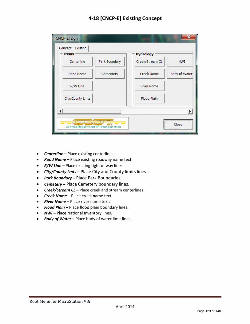
RootMenuforMicroStationV8i April 2014
4‐18 [CNCP‐E] Existing Concept
Centerline – Place existing centerlines.
Road Name – Place existing roadway name text.
R/W Line – Place existing right of way lines. City/County Lmts – Place City and County limits lines.
Park Boundary – Place Park Boundaries.
Cemetery – Place Cemetery boundary lines. Creek/Stream CL – Place creek and stream centerlines.
Creek Name – Place creek name text.
River Name – Place river name text.
Flood Plain – Place flood plain boundary lines.
NWI – Place National Inventory lines.
Body of Water – Place body of water limit lines.
Page 129 of 140

RootMenuforMicroStationV8i April 2014
4‐18 [CNCP‐E] Existing Concept (continued)
Boundary – Place existing property lines.
Owner Name – Place existing property owner name text.
Utility Easement – Place existing Utility Easement lines.
Wetland – Place Existing Wetland boundary lines.
Arch Boundary – Place Archeological boundary lines.
Arch Text – Place Archeological text.
Hist Boundary – Place Historical boundary lines.
Hist Hatching – Place Historical boundary cross hatching.
Haz‐Mat – Place Hazardous Material boundary lines.
End Species – Place Endangered Species boundary lines.
Haz Waste – Place Hazardous boundary lines.
Close ‐ Closes the “[CNCP‐E] Dgn” menu and returns the user to the “Root Menu”.
Page 130 of 140
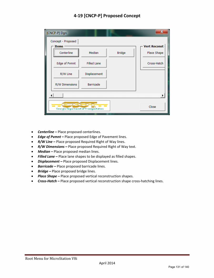
RootMenuforMicroStationV8i April 2014
4‐19 [CNCP‐P] Proposed Concept
Centerline – Place proposed centerlines.
Edge of Pvmnt – Place proposed Edge of Pavement lines.
R/W Line – Place proposed Required Right of Way lines.
R/W Dimensions – Place proposed Required Right of Way text.
Median – Place proposed median lines.
Filled Lane – Place lane shapes to be displayed as filled shapes.
Displacement – Place proposed Displacement lines.
Barricade – Place proposed barricade lines.
Bridge – Place proposed bridge lines.
Place Shape – Place proposed vertical reconstruction shapes.
Cross‐Hatch – Place proposed vertical reconstruction shape cross‐hatching lines.
Page 131 of 140

RootMenuforMicroStationV8i April 2014
4‐19 [CNCP‐P] Proposed Concept (continued)
100 Scale Border through 300 Scale Border – Place plotting border at the scale indicated by each of the three button options.
100 Scale Legend through 300 Scale Legend – Place concept legend cell at the scale indicated by each of the three button options.
100 Sca Match Ln through 300 Sca Match Ln – Place plotting match lines at the scale indicated by each of the button options. (Note “300 Scale” is temporarily unavailable.)
Place Stamp – Place concept stamp cell.
North Arrow – Place concept North Arrow cell.
Page 132 of 140

RootMenuforMicroStationV8i April 2014
4‐19 [CNCP‐P] Proposed Concept (continued)
Border – Place Location Map border cell.
Pointer Flag – Place Pointer Flag cell.
Place Stamp – Place Concept Stamp cell.
North Arrow – Place Location Map North Arrow cell.
Border – Place Plan Book border cell.
North Arrow 50 through North Arrow 200 – Place North Arrow cell at the scale indicated by each of the three button options.
Place Stamp – Place Concept Stamp cell.
Match Lines – Place Match Lines.
Page 133 of 140
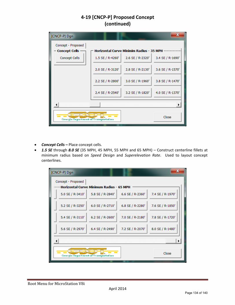
RootMenuforMicroStationV8i April 2014
4‐19 [CNCP‐P] Proposed Concept (continued)
Concept Cells – Place concept cells.
1.5 SE through 8.0 SE (35 MPH, 45 MPH, 55 MPH and 65 MPH) – Construct centerline fillets at minimum radius based on Speed Design and Superelevation Rate. Used to layout concept centerlines.
Page 134 of 140

5-1 Tools - Expanded
The following sections provide an expanded description of the functions of the GDOT Root Menu Tools section that is included in the GDOT Workspace for MicroStation V8i.
Page 135 of 140

RootMenuforMicroStationV8i April 2014
5‐2 LevelWorks
ATMS‐On / ATMS‐Off through XSEC‐On / XSEC‐Off – Turn on/off the current DGN file level display for levels named ATMS*. The menu is divided into 36 sections based on the Level Library root level names: ATMS, BRDG, CNCP, CNLY, DRNG, ECON, ENVE, ENVP, FCON, HLT, Level, LGHT, LIMT, LNSC, MAIN, MNTC, PROF_E, PROF_P, PROP, QTYS, QUAD, RAST, REQD, RWTB, SGNL, SHT, SIGN, STE, TOPO, TRDG, TYPS, UTLE, UTLP, WALL, WPRO and XSEC.
Level Manager – Opens the MicroStation Level Manager utility.
Close – Closes the “LevelWorks” menu and returns the user to the “Root Menu”.
Page 136 of 140

RootMenuforMicroStationV8i April 2014
5‐3 GPlot PDF Plotting
“GDOT – GPlot PDF Plotting”
Documentation for the “GDOT – GPlot PDF Plotting” application is available from the
“Help” tab on the GDOT Root Menu.
Page 137 of 140

6-1 Miscellaneous Items
The following sections contains additional information to aid in the use of the GDOT Root Menu that is included in the GDOT Workspace for MicroStation V8i.
Page 138 of 140

RootMenuforMicroStationV8i April 2014
6‐2 Other Sources of Information
The GDOT Electronic Data Guidelines (EDG) and the GDOT Plan Presentation Guide (PPG) as well as other documents and downloads are available from the GDOT Repository for Online Access to Documentation and Standards (R.O.A.D.S.) website. http://www.dot.ga.gov/doingbusiness/PoliciesManuals/roads/Pages/default.aspx
Page 139 of 140

RootMenuforMicroStationV8i April 2014
6‐3 Questions or Comments
For questions or comments about this document or any other MicroStation related issue, please contact the GDOT Solutions Center help desk. GDOT Solutions Center Phone: (404)631‐1220 Email: [email protected] (When submitting issues to the Solutions Center please specify a subject line of “MicroStation” so the issue will be assigned to the correct personnel.)
Page 140 of 140