GDI manual V2.6
40
G S M D O O R I N T E R C O M GDI User and programming manual V 2.6
Transcript of GDI manual V2.6

G S M D O O R I N T E R C O M
GDI
User and programming manual V 2.6

1
Basic technical parametres: Power supply: 12 (9-24) V AC/DC, 500mA
(optionally integrated ACU 2000mAh for cca 48h of operation)
GSM : 850/900/1800/1900 MHz dimension: 185 mm x 99 mm x 40 mm buttons: 1 or 2 up selected casing
(for every button max. 7 phone numbers dialled progressivelly)
relay: 2x relay with switching contact Input: 0/5V
Basic features:
GSM Door Intercom is usefull for different installation. You just insert SIM card and connect power supply, eventually connect el.lock. For its operation is used GSM network – so you dont need any telephone line or other cables. • Model with 1 or 2 buttons. Under each button you can
programm up to 7 phone numbers which are after button press progressivelly dialled.
• Automatic regulation of microphone volume. • 2 independent , remotely controlled switching relays with
different ways of activation (activation by ringing or by code during call, by button press, etc...)
• Recording of numbers from which you activated the relay by ringing
• 1 input for connection for example alarm (alerting by SMS) or for control of gate(door) opening (beeps during call) etc..
• Voice signalling of different events (for example. „ wait please“, „Open“ , etc...

2
Function:
Hands free GSM phone with preprogrammed phone numbers for 1 or 2 buttons with name cards:
1. Outgoing call: After button press is dialled first number from saved list of numbers. The numbers are saved under names ABUTTON1 to ABUTTON7 – it means first number under name ABUTTON1. When called party is busy or not available then automatically second number under name ABUTTON2 is dialled etc.. When called party picks up the call the connection is established and next numbers are not dial (the same valid for second button and line BBUTTON).
2. Incoming call: up settings will be incoming call picked up either for all calls or for saved numbers on SIM card only. (connection for saved numbers only). GDI might also reject incoming calls (see later in relay function). Before picks up might GDI alert by preprogrammed melody ( adjustable) . (Notification for call establishing – listen in control).
2 remotely controlled switching relay. Each can be controlled up settings by different ways:
1. By ringing – incoming call is rejected (confirmation of command accept) and simoultaneously is activated selected relay for preprogrammed time. Selected relay can be activated:
a. only from numbers saved in the phone list of the SIM card, or
b. from any number . 2. By code – during voice communication (incoming as
same as outgoing call) . The 1 digit code by DTMF might be dialled by called party for relay activation ( for preprogrammed time). For each relay you can programm different code.

3
3. By SMS – you can remotely switch ON/OFF selected relay or activate relay for certain time mention in SMS. Relays might be controlled only from preprogrammed numbers at GDI SIM card.
4. camera mode – selected relay is ON by picking up the call and it is OFF by hanging up the call.
5. lighting mode – selected relay is ON by picking up the call and it stays ON for preprogrammed time after hang up.
6. button mode – selected relay is ON after button press and stays ON for preprogrammed time.
1 adjustable input :
1. SMS sending „ALARM ON“ to preprogrammed number when input is short circuit against ground. SMS „ALARM OFF“ to next preprogrammed number when input is disconnected. It might be programmed 1 number only (ON/OFF). Then is send 1 SMS only up selected status.
2. opening detection. When input is activated during call (for example by gate ( door) opening ) the GDI generates into a call 3 short beeps for time of input activation.
Voice signalling of different status. Up settings might be different status signalling by voice . ( language adjustable). When is voice signalling presented during a call it is hearable on both sides of connection (for example „open“) Detection of start / restart. GDI indicates the start device (power) switch relay1 on 7s. This function can be used for example to automatically open after restoration of power supply, remote reboot any device (ringing) with automatic restart after power is restored, etc.

4
Installation
Assembly of front panel
CAUTION! During assembly of front panel zou might connect/disconnect speaker connector (via schematics) Assembly of cards backlighting

5
GDI Wall mounting Wall mounting assembly you make by attached screws (5mm).

6
Replacing backlighting cards after wall mounting
Cards inserting (name cards)
Every button has individual card hold by plastic flag. (via picture).

7
Control emelents and connection
Switch For operation put to position ON
SIM reader For operation insert the SIM
Setting of speaker loudness Loudness is also possible setup by parametr
input
Relay 2
Relay 1 PSU
Speaker screw terminal

8
Examples of relay connection
1. Basic connection - 2 electrical locks and possibility control 2 doors ( gates)
2. 2x PSU – possibility to use 2x independent PSU. One for GDI and second for electrical locks. The electrical lock 2 is connected inversaly (fire emergency doors).
3. External camera or lighting activation. 4. Electrical lock and additional bell combination.
CAUTION! Relay contacts cant close 230V directly.To control directly 230V devices you must use contactor.
1 2
3 4

9
1
2
3 4
5
Start
1. connect antenna and insert the SIM
We recommend use SIM without PIN. When you need PIN setup PIN 1234.
Release the SIM holder (1).
Move it up (2).
Insert the SIM in correct position (3) to the holder. Close the SIM holder (4).
Pull the SIM holder for lock up (5)

10
Note: All programmed parametres are saved on the SIM. The SIM you can insert into GDI already preprogrammed or setup GDI after switching ON ( via bellow).
When you want use calls rejection ( ringing), ask your GSM provider to switch OFF voice mail at used SIM card!
SIM preprogramming
1. SIM which you desire to use insert to various mobile phone.
2. When PIN is setup – cancel it (or setup PIN to 1234) 3. When you will want to make remote setting save on the
SIM phone number of desired mobile under name ADMIN1.
4. On the SIM save phone number which should be dial after pressing button 1 (A), under name „ABUTTON1“.
5. When you have GDI with 2 numbers – save on the SIM also phone number which will be dial after pressing button 2 (B) , under name „BBUTTON1“.
6. When you want dial automatically next numbers ( when first number is busy or not available) then save those numbers under appropriate names ABUTTON2..7 and BBUTTON2..7
7. Similiary you can programm setting of all parametres (programming table at the end of manual)
The way of phone numbers saving on the SIM depends on mobile phone type. Please double check that you save numbers to SIM card and not to internal mobile phone memory!
11
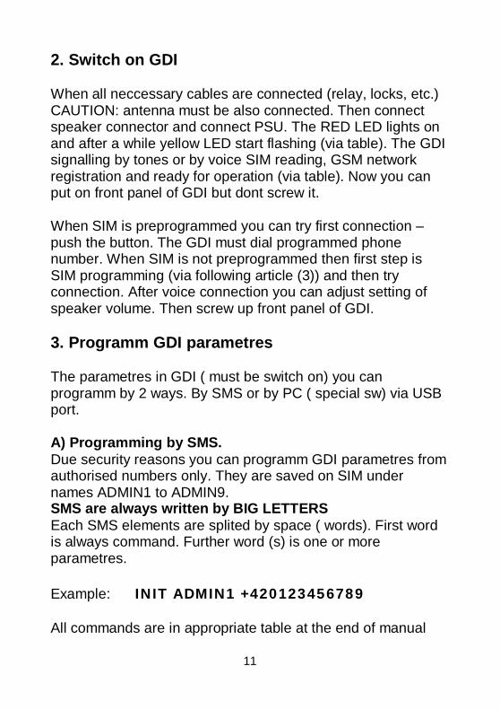
2. Switch on GDI
When all neccessary cables are connected (relay, locks, etc.) CAUTION: antenna must be also connected. Then connect speaker connector and connect PSU. The RED LED lights on and after a while yellow LED start flashing (via table). The GDI signalling by tones or by voice SIM reading, GSM network registration and ready for operation (via table). Now you can put on front panel of GDI but dont screw it.
When SIM is preprogrammed you can try first connection – push the button. The GDI must dial programmed phone number. When SIM is not preprogrammed then first step is SIM programming (via following article (3)) and then try connection. After voice connection you can adjust setting of speaker volume. Then screw up front panel of GDI.
3. Programm GDI parametres
The parametres in GDI ( must be switch on) you can programm by 2 ways. By SMS or by PC ( special sw) via USB port.
A) Programming by SMS. Due security reasons you can programm GDI parametres from authorised numbers only. They are saved on SIM under names ADMIN1 to ADMIN9. SMS are always written by BIG LETTERS Each SMS elements are splited by space ( words). First word is always command. Further word (s) is one or more parametres. Example: INIT ADMIN1 +420123456789 All commands are in appropriate table at the end of manual

12
1. During first setting when SIM doesnt contents any ADMINx name is neccessary such number insert to SIM by SMS with command INIT. SMS you can send from various number. When SIM already contents even one number under name ADMINx the command is ignored.
2. When you need control relay eventually setup GDI from next ADMIN numbers perform following: from mobile phone with ADMINx number send progressivelly SMS to GDI with numbers of next ADMINx in SMS format: WRITE ADMIN2 +420xxxxxxxxx (WRITE ADMIN3… etc.)
3. From mobile phone with numbers ADMINx send progressively SMS to GDI with numbers which should be dial after button press, SMS format: WRITE ABUTTON1 +420xxxxxxxxx (WRITE BBUTTON1… etc..)
4. Up your needs send next SMS with other parametres for opening by ringing, SMS alarm sending , etc..
5. Setup parametres GDI (via table). Parametres you can setup individually for each parametr appropriate SMS. When you need setup more parametres simoultaneously we recommend use SMS for batch setting. By SMS „READ PAR“ read firstly current setting to your mobile.
By editor of SMS messages change at received SMS word READ to WRITE as same as adjust parametres up your needs. Such adjusted SMS send back to GDI as reply. The parametres will be setup. A) Setting by PC through USB via GDIset ( optional)
1. Connect MiniUSB cable to PC as same as to programming module – green LED must light on at the module. During first usage USB driver might be installed. USB driver is available at attached CD.

13
2. Remove front cover of GDI and insert connector of programing modul into GDI (via picture). On programming modul must light on red LED
(It is flashing same way like yellow LED on GDI) 3. Run GDIset programm and setup appropriate port. 4. Program control GDI connection. After that display GSM
signal strength and voltage on GDI (back up ACU). Now you can programm:
Monitor mode
For parametres programming stop firmware running in GDI. For operation monitoring dont press! Stop GDI running!
Identification of seriál line connection
After GDI voice connection will show voltage in GDI
After GDI voice connection will show GSM signal strength

14
Programming mode
After button press STOP programm sends to GDI command for stop and wait for GDI response (via )
After click to button monitor is shown GDI operation (when operation is not stoped by button STOP)
Record savings from monitor to file (for service purposes – record sending)
Waiting for GDI response

15
Item Buttons It is designed for programming phone numbers under each buttons
Item for 2 buttons
Field to programm up to 7 phone numbers
Item for 1 button
Field to programm up to 7 phone numbers for upper button Saving of all programmed parametres including numbers to GDI
Reading of all programmed parametres including numbers from GDI Saving of all programmed parametres including numbers to PC Reading of all programmed parametres including numbers from PC GDIset version and fw GDI SIM number of position
Field to programm up to 7 phone numbers for second button
GSM provider where is GDI registrated

16
Item Phone Book Phone book of authorised numbers for ringing opening as same as automatic call receiving.
Position for name
Position for phone number
Add line above cursor
Delete line with cursor
Find inserted name

17
Item Setting
Way of incoming call receiving: - reject (opening by ringing) - automaticaly picked up calls from numbers at list only - pick up all calls
Signalization - Informing GDI tones - Ringing during incoming call - Voice signalling
Waiting Call Waiting to dial the next number on the list of button.
Item Calls
Loudness of speaker setting
Loudness of microphone setting

18
Item relay
Parametres setting for relay 1
Parametres setting for relay 2
Relay mode: - camera - light - button - control by SMS
Relay control by ringing only from SIM phone numbers
DTMF code for relay activation during a call
Relay time of activation
Relay control by ringing from all phone numbers

19
Item SMS
Number where will be sent SMS „ALARM ON” when input is activated
Number where will be sent SMS „ALARM OFF” when input is deactivated
Input mode: - Input deactivated - Tones when input is activated
during a call (open signal) - sending SMS
Sending SMS to ADMIN1 with list of numbers which activated relay by ringing.
Activation of time settings from GSM network

20
Item ADMIN numbers setting
Field to save up to 7 ADMIN numbers

21
Item Service It is designed for upgrade of firmware and voice messages in GDI. CAUTION! Unauthorised manipulation can blocked the unit.
List of files you want record to GDI ( manually editable)
Reading of list from PC
List erasing
Start of files saving from list to GDI. Indicator shows the process of savings.
Select and play ringing tone
Savings of selected ringing tone to GDI

22
When all neccessary is setup then save it by button Save to GDI.
Return from programming mode to monitor mode (restart of GDI)
GDI behaviour after restart is the same like during power supply connection (tones,eventually voice messages).
To return to monitor mode (run GDI) click on button „Run“. Programm detects GDI runs the same way like stop:

23
Table of SMS commands command ( SMS) Functionality Des
READ STAT Reading of GDI status (firmware, time, relays status etc.)
READ PAR Reading of all setup parametres
READ JMENO Reading of phone number for NAME
CLR JMENO Erasing phone number for NAME
INIT ADMIN1 +420cc…c Inicialization – first GDI setting – parametres you can programm from number ADMIN1 +420cc..c
SET REL1 ON Activation relay 1
SET REL1 OFF Deactivation relay 1
SET REL1 ON xx Activation relay1 for xx minutes
(xx=00 -99)
SET REL2 ON Activation relay 2
SET REL2 OFF Deactivation relay 2
SET REL2 ON xx Activation relay 2 for xx minutes
(xx=00 -99)
WRITE NAME +420cc…c Saving of phone number under NAME
WRITE PAR VOLIN:x Saving of microphone loudness
[x=1-7]
4
WRITE PAR VOLOUT:x Saving of speaker loudness
[x=1-7]
4
WRITE PAR INCALL:x Processing of incoming call: x:
0 – calls rejected (ringing in)
1- calls received from SIM only (list)
2 – all calls received
0
SMS
mig
ht b
e se
nt fr
om A
DM
INx
num
bers
onl
y
WRITE PAR WRCALL:x Sending SMS with the numbers of which was to open up
0 – deactivated
1 - activated
0

24
WRITE PAR TMGSM:x Time setup up GSM network x:
0 – OFF
1 - ON
1
WRITE PAR TONE:x Setting of acoustic signalization x:
0 – switch OFF
1 – signalling by service tones
2 – ringing of incoming call is ON
4 – signalling by voice messages
and combination – for ex. 7 – all is ON
5
WRITE PAR INPMOD:x Input mode
x=0 – deactivated
x=1 – beeps into call (opening indication)
x=2 – during activation/deactivation sends SMS
WRITE PAR WAIT:xx Waiting to dial the next number on the list
xx – 10 to 90 sec. (by dozens)
20
WRITE PAR RL1COD:y Code for relay1 activation during call
y= 0-9
5
SMS
mig
ht b
e se
nt fr
om A
DM
INx
num
bers
onl
y
WRITE PAR RL1MOD:x Relay 1 modes
x=0 – control by SMS
x=1 – switch mode (ringing in only from SIM phone number or by code)
x=2 – camera mode (activated by pick up, deactivated by hang up)
x=3 – lighting mode (activated by pick up and stays ON for „activation time“ after hang up
x=4 – activated for „activation time“ after button press
x=5 - switch mode all (ringing in from all phone number or by code)
1

25
WRITE PAR RL1TMON:yy Relay1 activation time after ringing in or by code yy seconds
yy= 00-99
03
WRITE PAR RL1RING:x Relay1 activation by ringing in
x=0 – OFF
x=1 - ON
1
WRITE PAR RL2COD:y Code for relay2 activation during call
y=0-9
6
WRITE PAR RL2MOD:x Relay 2 modes
x=0 – control by SMS
x=1 – switch mode (ringing in only from SIM phone number or by code)
x=2 – camera mode (activated by pick up, deactivated by hang up)
x=3 – lighting mode (activated by pick up and stays ON for „activation time“ after hang up
x=4 – activated for „activation time“ after button press
x=5 - switch mode all (ringing in from all phone number or by code)
0
WRITE PAR RL2TMON:yy Relay2 activation time after ringing in or by code yy seconds
yy=00-99
05
WRITE PAR RL2RING:x Relay2 activation by ringing in
x=0 – OFF
x=1 - ON
0
WRITE ALARMON +420cc..c Savings of number for SMS „ALARM ON“
(input grounding)
WRITE ALARMOFF +420cc..c Savings of number for SMS „ALARM OFF“
(input disconnection)
CAL AT+CSQ Signal strength level

26
CAL AT+CPBR=x Info about number saved on position x
CAL AT+CCLK=“<time>“ Setup time in GDI <time>
Format <time>= yy/MM/dd,hh:mm:ss±zz
yy – year (00-99)
MM – month (01-12)
dd – day (01-31)
hh – hours (00-23)
mm – minutes (00 – 59)
ss – seconds (00 – 59)
±zz – time zone (-47..+48) hours
Command types: READ – command for reading parametres as same as phone numbers from SIM card CLR – command to erase phone numbers from SIM card. CAUTION! When you use SMS for numbers erasing then dont forget that one ADMINx number must stayed – otherwise remote settings will not be possible (neccessary to make new initialization). INIT – Initialization. During first setting when SIM doesnt includes any ADMINx number is neccessary to put such number on the SIM card.It is done by SMS with INIT command. The SMS might be sent from various number. When SIM card already has at least one number with name ADMINx the command is ignored. WRITE – command to save parametres as same as phone numbers to SIM card CAL – after command CAL you can put various AT command of used GSM module (for example: module reset, time setting etc.) . Those commands please use with appropriate knowledge only! It can caused blocking of whole unit!

27
Names function saved in phone book
NAME function ABUTTON1 - to this number GDI call when button is pressed (upper button)
- relay1 or relay2 activated by ringing in
- calls are automatically received from this number
ABUTTON2 - to this number is called from GDI when number under ABUTTON1 is busy, unreachable, not picked up a call for certain time
- relay1 or relay2 activated by ringing in
- calls are automatically received from this number
ABUTTON3 - to this number is called from GDI when number under ABUTTON2 is busy, unreachable, not picked up a call for certain
- relay1 or relay2 activated by ringing in
- calls are automatically received from this number
ABUTTON4 - to this number is called from GDI when number under ABUTTON3 is busy, unreachable, not picked up a call for certain
- relay1 or relay2 activated by ringing in
- calls are automatically received from this number
ABUTTON5 - to this number is called from GDI when number under ABUTTON4 is busy, unreachable, not picked up a call for certain time
- relay1 or relay2 activated by ringing in
- calls are automatically received from this number
ABUTTON6 - to this number is called from GDI when number under ABUTTON5 is busy, unreachable, not picked up a call for certain time
- relay1 or relay2 activated by ringing in
- calls are automatically received from this number
ABUTTON7 - to this number is called from GDI when number under ABUTTON6 is busy, unreachable, not picked up a call for certain time
- relay1 or relay2 activated by ringing in
- calls are automatically received from this number

28
BBUTTON1 - to this number GDI call when down button is pressed (version with 2 buttons)
- relay1 or relay2 activated by ringing in
- calls are automatically received from this number
BBUTTON2 - to this number is called from GDI when number under BBUTTON1 is busy, unreachable, not picked up a call for certain time
- relay1 or relay2 activated by ringing in
- calls are automatically received from this number
BBUTTON3 - to this number is called from GDI when number under BBUTTON2 is busy, unreachable, not picked up a call for certain time
- relay1 or relay2 activated by ringing in
- calls are automatically received from this number
BBUTTON4 - to this number is called from GDI when number under BBUTTON3 is busy, unreachable, not picked up a call for certain time
- relay1 or relay2 activated by ringing in
- calls are automatically received from this number
BBUTTON5 - to this number is called from GDI when number under BBUTTON4 is busy, unreachable, not picked up a call for certain time
- relay1 or relay2 activated by ringing in
- calls are automatically received from this number
BBUTTON6 - to this number is called from GDI when number under BBUTTON5 is busy, unreachable, not picked up a call for certain time
- relay1 or relay2 activated by ringing in
- calls are automatically received from this number
BBUTTON7 - to this number is called from GDI when number under BBUTTON6 is busy, unreachable, not picked up a call for certain time
- relay1 or relay2 activated by ringing in
29
- calls are automatically received from this number
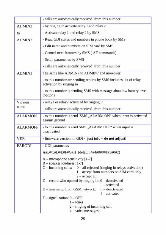
ADMIN2
to
ADMIN7
- by ringing in activate relay 1 and relay 2
- Activate relay 1 and relay 2 by SMS
- Read GDI status and numbers in phone book by SMS
- Edit name and numbers on SIM card by SMS
- Control next features by SMS ( AT commands)
- Setup parametres by SMS
- calls are automatically received from this number
ADMIN1 The same like ADMIN2 to ADMIN7 and moreover:
- to this number are sending reports by SMS includes list of relay activation by ringing in
- to this number is sending SMS with message abou low battery level (option)
Various name
- relay1 or relay2 activated by ringing in
- calls are automatically received from this number
ALARMON - to this number is send SMS „ALARM ON“ when input is activated against ground
ALARMOFF - to this number is send SMS „ALARM OFF“ when input is deactivated
VER - firmware version in GDI - just info – do not adjust!
PARGDI - GDI parametres
A#B#C#D#E#F#G#H (default 4#4#0#0#1#5#0#2)
A – microphone sensitivity [1-7] B – speaker loudness [1-7] C – incoming calls: 0 – all rejected (ringing in relays activation)
1 – accept from numbers on SIM card only 2 – accept all
D – record who opened by ringing in: 0 – deactivated 1 – activated E – time setup from GSM network: 0 – deactivated
1 – activated F – signalization: 0 – OFF
1 – tones 2 – ringing of incoming call 4 – voice messages

30
all combination available – for ex. All is ON = 7
G – input mode: 0 – input deactivated 1 – when input is grounded beeps into call
(signalling of opened door) 2 – SMS when input is activated/deactivated
H - waiting to dial the next number on the list [1-9]
value is in dozens seconds PARRL1 - parametres for relay 1
A#B#CC#D (default 5#1#03#1)
A – DTMF code for relay activation during call [0-9] B – relay mode: 0 – SMS mode, control by SMS
1 – switch mode, activated by ringing in from SIM phone numbers or by DTMF code during call
2 – camera mode (activated by pick up, deactivated by hang up)
3 – lighting mode (activated by pick up, stays activated for „activation time“ after hang up
4 – button mode (activated for „activation time“ after button press
5 – switch mode all, activated by ringing in all phone numbers or by DTMF code during call
CC – activation time [00-99] D – relay activation by ringing in: 0 – deactivated
1 - activated PARRL2 - parametres for relay 2
A#B#CC#D (default 6#0#05#0)
A – DTMF code for relay activation during call [0-9] B – relay mode: 0 – SMS mode, control by SMS
1 – switch mode, activated by ringing in from SIM phone numbers or by DTMF code during call
2 – camera mode (activated by pick up, deactivated by hang up)
3 – lighting mode (activated by pick up, stays activated for „activation time“ after hang up
4 – button mode (activated for „activation time“ after button press
5 – switch mode all, activated by ringing in all phone numbers or by DTMF code during call
CC – activation time [00-99] D – relay activation by ringing in: 0 – deactivated
1 - activated
31
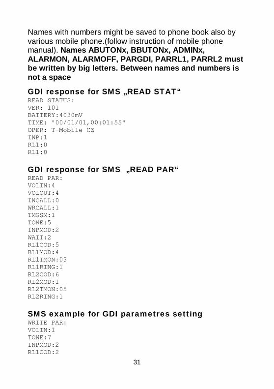
Names with numbers might be saved to phone book also by various mobile phone.(follow instruction of mobile phone manual). Names ABUTONx, BBUTONx, ADMINx, ALARMON, ALARMOFF, PARGDI, PARRL1, PARRL2 must be written by big letters. Between names and numbers is not a space
GDI response for SMS „READ STAT“ READ STATUS: VER: 101 BATTERY:4030mV TIME: "00/01/01,00:01:55" OPER: T-Mobile CZ INP:1 RL1:0 RL1:0 GDI response for SMS „READ PAR“ READ PAR: VOLIN:4 VOLOUT:4 INCALL:0 WRCALL:1 TMGSM:1 TONE:5 INPMOD:2 WAIT:2 RL1COD:5 RL1MOD:4 RL1TMON:03 RL1RING:1 RL2COD:6 RL2MOD:1 RL2TMON:05 RL2RING:1 SMS example for GDI parametres setting WRITE PAR: VOLIN:1 TONE:7 INPMOD:2 RL1COD:2

32
GDI tones
Except ordinary tones and signalling of GSM communication (ringing tone, busy tone, different provider´s messages) the GDI has own signalling of operation (via setting possibilities).
ƒƒƒƒƒƒ≤ƒƒƒƒƒƒƒƒƒƒƒƒƒƒƒƒƒƒƒƒƒƒƒƒƒƒƒƒƒƒƒƒƒƒƒƒƒƒƒƒƒƒƒƒƒƒƒƒƒƒƒƒƒƒƒƒ
High tone – Alerting GDI detects not registration to GSM net (antenna not connected , wrong PIN,), dialling number to GSM etc..
ƒƒƒƒƒƒƒƒƒƒƒƒƒƒƒƒƒƒƒƒƒƒƒƒƒƒƒ≤ƒƒƒƒƒƒƒƒƒƒƒƒƒƒƒƒƒƒƒƒƒƒƒƒƒƒƒƒƒƒƒƒƒƒƒ
Medium level tone – verify action GDI reads the SIM, registrate to network, answer for SMS, measure voltage etc...
ƒƒƒƒƒƒƒƒƒƒƒƒƒƒƒƒƒƒƒƒƒƒƒƒƒƒƒƒƒƒƒƒƒƒƒƒƒƒƒƒƒƒƒƒƒƒƒƒ≤ƒƒƒƒƒƒƒƒƒƒƒƒƒƒ
Low level tone – error GDI detects error (for example: low voltage, no GSM reaction for command. Can react by unit restart
≤ƒƒƒƒƒƒƒƒƒƒƒƒƒƒƒƒƒƒƒƒ ƒ≤ƒƒƒƒƒƒ≤ƒƒƒƒƒ≤ƒƒƒƒƒ≤ ƒƒƒƒƒƒƒƒƒƒƒƒƒƒƒƒƒƒƒƒƒ
High tone follow by medium level tones in period cca 5 sec. start a initialization of GDI (registration to network, SIM reading etc..)
ƒƒƒƒƒ≤ƒƒ≤ƒƒ≤ƒƒ≤ƒƒ≤ƒƒƒ ƒƒƒƒƒƒƒƒƒƒƒƒƒƒƒƒƒƒƒƒƒƒƒƒƒƒƒƒƒƒƒƒƒƒƒƒƒƒƒƒƒƒ
High tone repeated GDI detects disconnection from GSM net (antena disconnected, wrong PIN....)
ƒƒƒƒ≤ƒƒƒƒƒƒƒƒƒƒƒƒƒƒƒƒ ≤ƒ≤ƒƒƒƒƒƒƒƒƒƒƒƒƒƒƒƒƒƒ ƒƒƒƒƒƒƒƒƒƒƒƒƒƒƒƒƒƒƒƒƒ
Medium level tone repeated during button holding, high tone Button press detection, dial of preprogrammed number
ƒƒƒƒƒƒ≤ƒƒƒƒƒƒƒƒƒƒƒƒƒƒƒƒƒƒƒƒƒƒƒƒƒƒƒƒƒƒƒƒƒƒƒƒƒƒƒƒƒƒƒƒƒƒƒƒƒƒƒƒƒƒƒƒ
High tone, once after dial number to GSM called party reached

33
LED signalling
¤¤¤¤¤¤¤¤¤¤¤
Permanent light GDI power supply is ON
Red LED
Not light GDI switched OFF
Not light GDI switched OFF
¤¤¤ ¤¤¤ ¤¤¤ Flashing space and light same duration GDI is not registrated to GSM network
▌ ▌ ▌ Short flashing with frequency 2 sec. GDI registrated to GSM network
Yellow LED
¤¤¤¤¤¤¤¤¤¤¤¤ Permanent light GDI establish a call or it is a call or GDI in programmiing mode

34
GDI with backup battery
If you have already GDI with a backup battery in the delivery, pull out before operation insulating tape.
Do not store the device with a battery pack without insulating tape! Self-discharge can damage the battery, not covered by the manufacturer's warranty.

35
Inserting the backup battery:
• Use only batteries approved by the manufacturer: Li-Ion 18650 2000-2600mAh
• Observe the polarity. Never place the inverted battery! It can damage the device.
Attention to the polarity! + battery is cap isolated from the casing
Before inserting the battery, off GDI using the switch (red LED goes out)

36
The manufacturer is not liable for defects caused by failure to comply with the prescribed procedure.
First, on the + side
Again turn on GDI: moving the switch to the ON position

37
Technical parametres:
Dimension 185 mm x 99 mm x 40 mm Operating position various Operating condition temperature: -20 to + 50°C
humidity: 10% ÷ 80% při 30° C Power supply 12 (9-24) V AC/DC, 500mA
(optionaly integrated ACU 2000mAh for cca 48h of operation
Buttons 1 or 2 up casing
(for each button max 7 numbers progressively dialled)
Relay 2x switching contact Max. voltage 48V when I<1A Max. Current 2A when U<30V Activation time by code 1 to 99 sec Activation time by SMS 1 to 99 min Detection of start / restart. relay1 contact switch to 7s Input: 0/5V GSM: networks 850/900/1800/1900 MHz SIM 3V, 1.8V

38
Note

39
Alphatech spol. s r.o. Jeremenkova 88 140 00 Praha 4
tel. 272 103 335, fax. 272 103 334 e-mail: [email protected]
internet: http://www.alphatech.cz naše souřadnice GPS (WGS 84) N 50°02′35.5″ E 14°25′42.0″
9.10.2015