GB PNR/PNE Series - VAXTEEL · GB PNR/PNE Series Operating and ... PNR142 D 344 338 355 300 188 205...
28
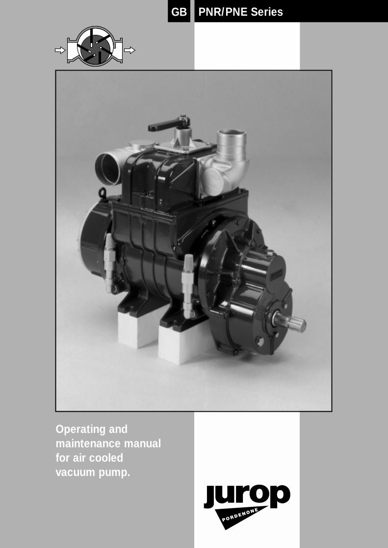
PNR/PNE Series GB Operating and maintenance manual for air cooled vacuum pump.
Transcript of GB PNR/PNE Series - VAXTEEL · GB PNR/PNE Series Operating and ... PNR142 D 344 338 355 300 188 205...
PNR/PNE SeriesGB
Operating andmaintenance manualfor air cooledvacuum pump.


3
Index
1. General advises
1.1 Introduction pag. 4
1.2 Request of spare parts 4
2. Technical specifications
2.1 Dimensions pag. 4
2.2 Technical data 6
2.3 Performances 6
2.4 Lubrication system 7
3. Safe-operating prescriptions
3.1 General suggestions pag. 7
3.2 Normal use of the pump 8
4. Installation
4.1 Checking at arrival of the goods pag. 8
4.2 Pump mounting/Drive connection 8
4.2.1 Hydraulic drive installation 9
4.3 Connection to the vacuum tank 9
5. Starting-up instructions
5.1 Oil level checking pag. 11
5.2 Starting-up of the pump 11
6. Running of the pump pag. 12
7. Maintenance
7.1 Ordinary maintenance pag. 12
7.1.1 Periodical checking 12
7.1.2 Wear of vanes checking 12
7.1.3 Lubrication adjustment 13
7.2 Extraordinary maintenance -- replacement of the vanes 14
8. Trouble-shooting, causes and remedies pag. 15
9. Parts list layout PNR-PNE
9.1 Spares PNR-PNE 72-82 D-HDR pag. 16
9.2 Spares PNR-PNE 72-82 M 18
9.3 Spares PNR-PNE 102-122 D-HDR 20
9.4 Spares PNR-PNE 102-122 M 22
9.5 Spares PNR 142 D-HDR 24
9.6 Spares PNR 142M 26

4
General advises
1.1. Introduction
This booklet contains the necessary instructions for a correct instal-lation, running, use and maintenance of the pump as well as somepractical suggestions for a safe operating.
The knowledge of the following pages will grant a long and troublefree operation of the pump.
It is recommended to :
• understand and apply closely the instructions before running thepump.
• keep the booklet at hand and have it known to all operators.
1.2. Request of spare parts
To avoid mistakes when ordering the spare parts make sure you in-dicate:
a) The model of the pump (see pump tag) . . . . . . . . . . . . PNR142
b) Serial number of the pump . . . . . . . . . . . . . . . . . . . . . X70012
c) Description of the parts (see parts list): . . . . . . . . . . . . . . .Vane
d) Quantity . . . . . . . . . . . . . . . . . . . . . . . . . . . . . . . . . . .no. 5 pcs
e) The code no. of the part . . . . . . . . . . . . . . . . . . . .16016.052.00
2. Technical specification
2.1. Dimensions
PN… D [direct drive]
DIN
961
1A
M12
16
GED
L
BA
83
C
ON
P
R
Q
øM
I
AS
AE
1 3
/8
F
S (k6)
TU
H
Model A B C D E F G H I L M N O P Q R S T UIN OUT
PN...72 D 298 284 309 153 207 232 65 G1 1/2 57 140 76-80 76 270 230 320 508 150 35 10 38PN...82 D 320 306 331 153 230 255 65 G1 1/2 57 140 76-80 76 270 230 320 508 150 35 10 38PN...102 D 320 313 329 153 237 253 72 (G2)* 64 185 80-100 100 285 255 345 550 168 40 12 43PN...122 D 353 346 362 153 269 285 72 (G2)* 64 185 80-100 100 285 255 345 550 168 40 12 43PNR142 D 344 338 355 300 188 205 95 (G2)* 64 257 80-100 100 320 270 340 562 210 40 12 43
*: only if foreseen with additional conveyor Ref. no. 1627102500
5
I
DIN
961
1A
A
B
E
G
16
F
CD AS
AE
1 3
/8
O
N
L
Q
P
øM
H
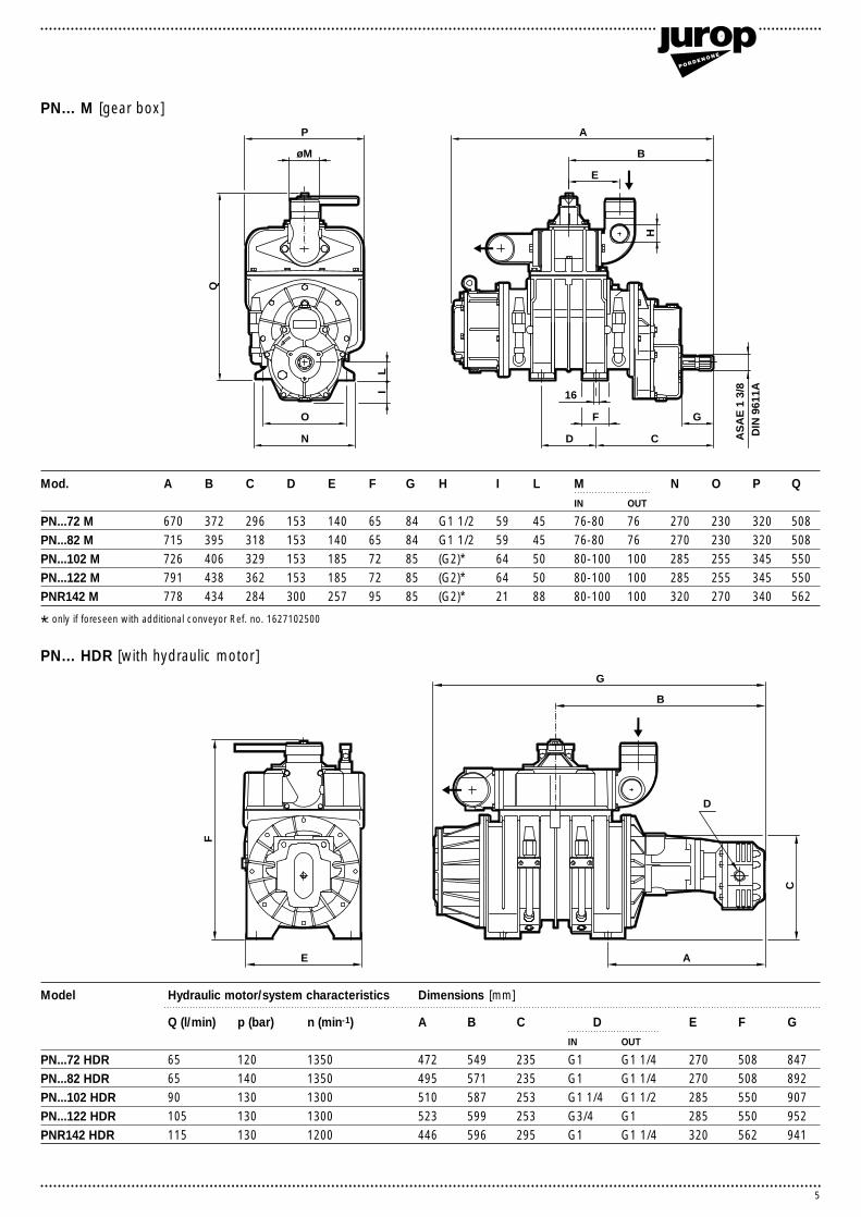
PN… M [gear box]
Mod. A B C D E F G H I L M N O P QIN OUT
PN...72 M 670 372 296 153 140 65 84 G1 1/2 59 45 76-80 76 270 230 320 508PN...82 M 715 395 318 153 140 65 84 G1 1/2 59 45 76-80 76 270 230 320 508PN...102 M 726 406 329 153 185 72 85 (G2)* 64 50 80-100 100 285 255 345 550PN...122 M 791 438 362 153 185 72 85 (G2)* 64 50 80-100 100 285 255 345 550PNR142 M 778 434 284 300 257 95 85 (G2)* 21 88 80-100 100 320 270 340 562
D
B
G
A
F
E
C
Model Hydraulic motor/system characteristics Dimensions [mm]
Q (l/min) p (bar) n (min-1) A B C D E F GIN OUT
PN...72 HDR 65 120 1350 472 549 235 G1 G1 1/4 270 508 847PN...82 HDR 65 140 1350 495 571 235 G1 G1 1/4 270 508 892PN...102 HDR 90 130 1300 510 587 253 G1 1/4 G1 1/2 285 550 907PN...122 HDR 105 130 1300 523 599 253 G3/4 G1 285 550 952PNR142 HDR 115 130 1200 446 596 295 G1 G1 1/4 320 562 941
PN… HDR [with hydraulic motor]
*: only if foreseen with additional conveyor Ref. no. 1627102500

6
2.2. Technical dataJurop’s sliding-vane, air-cooled vacuum pumps PNR and PNE arestandardly delivered with:• Asbestos-free tangential vanes • Automatic lubrication by means of volumetric pump and oil tank.• Change-over valve (4-way valve) for pressure and vacuum• Single piece, guided check valve• Suction and discharge connections made of aluminum alloy• Gearbox transmission with hardened, single piece splined driveshaft ASAE 1 3/8”. • Direct transmission with a.m. drive shaft or smooth shaft.• Counterclockwise rotation• PNR: cooled by air injection
Upon request:• Clockwise rotation• Drive by means of internal combustion engine, hydraulic motor ormechanical drive from a Power Take Off.• Pneumatic or hydraulic actuator on the change-over valve forpressure and vacuum
Automatic lubrication: the volumetric pump with vari-able flow, fitted on the rear part and inside the oil tank, injectsthe lubricating oil directly inside the vacuum pump, thereforeeliminating a manual adjustement of the oil flow.It results in a lower lubricating oil consumption and makes un-necessary a periodical lubrication checking and/or adjustment.
NOTA
2.3. Performances
Model PN...72 PN...82 PN...102 PN...122 PNR142Maximum speed PN... D min-1 1350 1350 1300 1300 1200
PN... M min-1 540 540 540 540 540Minimum speed PN... D min-1 700 700 700 700 700
PN... M min-1 300 300 300 300 300Air flow free air condition l/min 7200 8200 10200 12200 14200Air flow 60% vacuum rate l/min 6600 7600 9400 11200 12800Maximum vacuum % 93 93 92 92 90Maximum vacuum at continuous duty % 60 60 60 60 60Power required at 0,5 bar rel. (1,5 abs.) kW 11 12,5 16 19 20,5Max operating rel. pressure (abs.) bar 1 (2) 1 (2) 1 (2) 1 (2) 1 (2)Noise level: 60% vacuum, 7 m. c/w silencer PNE dB(A) 75 75 75 75 75
PNR dB(A) 78 78 78 78 78Weight PN... D kg 124 130 160 177 240
PN... M kg 136 142 173 190 255Oil consumption g/h 110÷130 110÷130 130÷150 130÷150 160÷170Oil tank capacity l 2,2 2,2 3,2 3,2 4Torque kgm2 0,2 0,23 0,35 0,40 0,58
Air
flow
(l/m
in)
Absolute pressure (bar)
Absolute pressure (bar)
Pow
er (k
W)
2 1.5 1 0.8 0.6 0.4 0.2 04.000
6.000
8.000
10.000
12.000
2 1.5 1 0.8 0.6 0.4 0.2 05
10
15
20
25
PNR 142
PNR 122
PNR 102
PNR 82
PNR 72
Vacuum degree ( % )0 20 40 60 80 100
14.000
PNR 142
PNR 122
PNR 102
PNR 82
PNR 72

7
3. Safe operating instructions
2.4. Pump’s lubrication
Recommended oils and greases for the lubrication of the housing and the rotor.
Brand AGIP ESSO SHELL ELF MOBIL BPISO VG 150 Radula 150 Nuray 150 Vitrea 150 Movixa 150 Rubrex 900 Energol CS 150
Recommended oil and greases for the lubrication of the gearbox and the ball bearings
Brand AGIP ESSO SHELL ELF MOBIL BPISO VG 220 Blasia 220 Spartan EP 220 Omala Oil 220 Reductelf SP 220 Mobilgear 630 Energol GR XP 220NLGI 2 (grease) GR MU EP2 Beacon EP2 Alvania EP2 Epexa 2 Mobilux EP2 Grease LTX2-EP
180
120
60
0
0 5 10 15 80% = vacuum
Tim
e [s
ec.]
Tank capacity [m3] Tank capacity [m3]
Tim
e [s
ec.]
60% = vacuum
180
PN...72
PN...82
PN...72PN...82
PN...102
PN...122PNR 142
PN...102
PN...122PNR 142
120
60
0
0 5 10 15 20
Evacuating time
PN...72 · PN...82 PN...102 · PN...122 · PNR 142
The diagram shows theevacuation time for atank of given capacity.The actual time isaffected by the airtightness of the wholevacuum system.
ATTENTION: STRICTLY COMPLY WITH THESEPRESCRIPTIONS!
3.1. General suggestions• Installation and maintenance have to be done with the machine to-tally disengaged from its drive system and must be performed byskilled personell. Disregarding of said safety prescription could resultin serious injury to the operator from moving machinery parts.• Operating personell must wear adequate clothing and protection.• When running the pump adequate protection for moving partsmust be used. If such protections are damaged they must be re-placed.
• Be aware that during heavy duty working conditions the pump’shousing can reach temperatures of over 60° centigrade. Use ade-quate means in order to avoid direct contacts with over-heated parts.• Take care when managing pumps that may have been in contactwith dangerous media.• To lift/move around the pump use an adequate belt or chain in-serted through the eyebolts on top of the pump. Rest the pump onsafe pedestals in order to avoid accidents.
8
4. Installation
4.1. Checking at arrival of the goodsUpon receipt check that the pump and accessories are not visiblydamaged.
4.2. Pump mounting-drive connectionThe pump must be installed so that it is easily accessible for inspectionand maintenance. It has also to be fixed on a rigid pedestal or stand,horizontal or slightly inclined, correctly dimensioned in order to avoid vi-brations or deformations.
ATTENTION: do foresee the neccessary room for maintenance. Tochange the vanes it is necessary to dismantle the oil tank on the rearof the pump.Necessary components for each of the described drive systems areavailable upon specific request.
For all the different drive systems make sure that therotation direction corresponds to the one shown bythe arrow placed on the front of the pump.
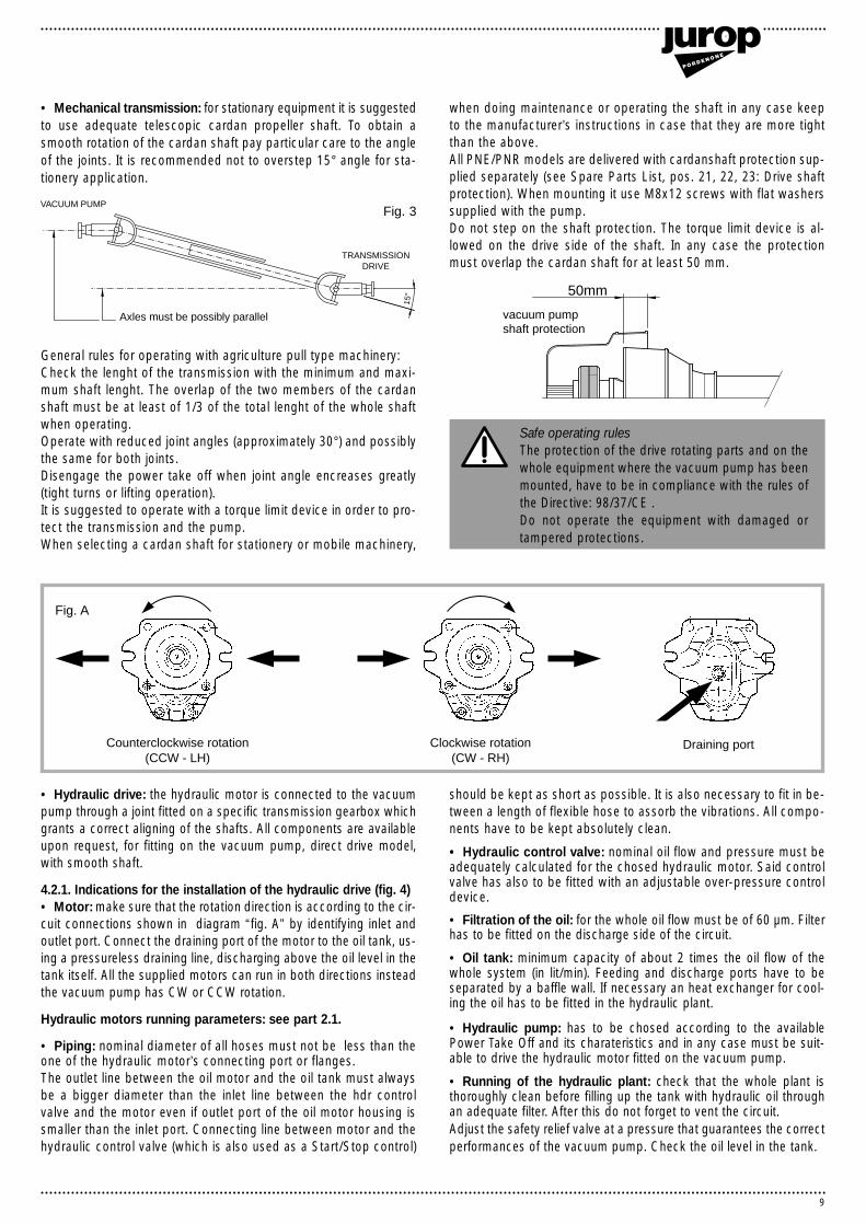
• Drive by belts and pulleys: the pulley has to be mounted on the«smooth shaft» of a direct drive pump model (Models PNR-PNE ... D)Proceed as indications of fig. 2.
ATTENTION: the pulley has to rest against the end-step of thesmooth drive shaft. Always use belts SPB or SPBX type.
�
Flection due to manual pressure�on the belts
Axles must be parallel
V-belts must be�exactly in line
16-20 mm�for each meter of wheel base
Fig. 2
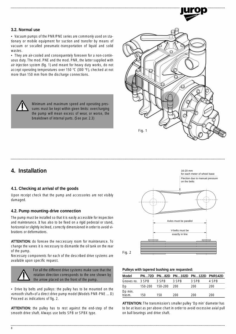
3.2. Normal use• Vacuum pumps of the PNR/PNE series are commonly used on sta-tionary or mobile equipment for suction and transfer by means ofvacuum or socalled pneumatic-transportation of liquid and solidwastes.• They are air-cooled and consequentely foreseen for a non-contin-uous duty. The mod. PNE and the mod. PNR, the latter supplied withair injection system (fig. 1) and meant for heavy duty works, do notaccept operating temperatures over 150 °C (300 °F), checked at notmore than 150 mm from the discharge connections.
Fig. 1
Pulleys with tapered bushing are requested:
Model PN…72D PN…82D PN…102D PN…122D PNR142DGrooves no. 3 SPB 3 SPB 3 SPB 3 SPB 4 SPBDp 150-200 150-200 200 200 200Dp min.trasm. 150 150 200 200 200
ATTENTION: The transmission’s smaller pulley ‘Dp min’ diameter hasto be at least as per above chart in order to avoid excessive axial pullon ball bearings and drive shaft.
Minimum and maximum speed and operating pres-sures must be kept within given limits: overchargingthe pump will mean excess of wear, or worse, thebreakdown of internal parts. (See par. 2.3)
9
• Hydraulic drive: the hydraulic motor is connected to the vacuumpump through a joint fitted on a specific transmission gearbox whichgrants a correct aligning of the shafts. All components are availableupon request, for fitting on the vacuum pump, direct drive model,with smooth shaft.
4.2.1. Indications for the installation of the hydraulic drive (fig. 4)• Motor: make sure that the rotation direction is according to the cir-cuit connections shown in diagram “fig. A” by identifying inlet andoutlet port. Connect the draining port of the motor to the oil tank, us-ing a pressureless draining line, discharging above the oil level in thetank itself. All the supplied motors can run in both directions insteadthe vacuum pump has CW or CCW rotation.
Hydraulic motors running parameters: see part 2.1.
• Piping: nominal diameter of all hoses must not be less than theone of the hydraulic motor’s connecting port or flanges.The outlet line between the oil motor and the oil tank must alwaysbe a bigger diameter than the inlet line between the hdr controlvalve and the motor even if outlet port of the oil motor housing issmaller than the inlet port. Connecting line between motor and thehydraulic control valve (which is also used as a Start/Stop control)
should be kept as short as possible. It is also necessary to fit in be-tween a length of flexible hose to assorb the vibrations. All compo-nents have to be kept absolutely clean.
• Hydraulic control valve: nominal oil flow and pressure must beadequately calculated for the chosed hydraulic motor. Said controlvalve has also to be fitted with an adjustable over-pressure controldevice.
• Filtration of the oil: for the whole oil flow must be of 60 µm. Filterhas to be fitted on the discharge side of the circuit.
• Oil tank: minimum capacity of about 2 times the oil flow of thewhole system (in lit/min). Feeding and discharge ports have to beseparated by a baffle wall. If necessary an heat exchanger for cool-ing the oil has to be fitted in the hydraulic plant.
• Hydraulic pump: has to be chosed according to the availablePower Take Off and its charateristics and in any case must be suit-able to drive the hydraulic motor fitted on the vacuum pump.
• Running of the hydraulic plant: check that the whole plant isthoroughly clean before filling up the tank with hydraulic oil throughan adequate filter. After this do not forget to vent the circuit.Adjust the safety relief valve at a pressure that guarantees the correctperformances of the vacuum pump. Check the oil level in the tank.
Counterclockwise rotation�(CCW - LH)
Clockwise rotation�(CW - RH)
Draining port
Fig. A
• Mechanical transmission: for stationary equipment it is suggestedto use adequate telescopic cardan propeller shaft. To obtain asmooth rotation of the cardan shaft pay particular care to the angleof the joints. It is recommended not to overstep 15° angle for sta-tionery application.
General rules for operating with agriculture pull type machinery:Check the lenght of the transmission with the minimum and maxi-mum shaft lenght. The overlap of the two members of the cardanshaft must be at least of 1/3 of the total lenght of the whole shaftwhen operating.Operate with reduced joint angles (approximately 30°) and possiblythe same for both joints. Disengage the power take off when joint angle encreases greatly(tight turns or lifting operation).It is suggested to operate with a torque limit device in order to pro-tect the transmission and the pump.When selecting a cardan shaft for stationery or mobile machinery,
when doing maintenance or operating the shaft in any case keepto the manufacturer’s instructions in case that they are more tightthan the above.All PNE/PNR models are delivered with cardanshaft protection sup-plied separately (see Spare Parts List, pos. 21, 22, 23: Drive shaftprotection). When mounting it use M8x12 screws with flat washerssupplied with the pump.Do not step on the shaft protection. The torque limit device is al-lowed on the drive side of the shaft. In any case the protectionmust overlap the cardan shaft for at least 50 mm.
Safe operating rulesThe protection of the drive rotating parts and on thewhole equipment where the vacuum pump has beenmounted, have to be in compliance with the rules ofthe Directive: 98/37/CE .Do not operate the equipment with damaged ortampered protections.
Axles must be possibly parallel
VACUUM PUMP
TRANSMISSION�DRIVE
15°�
Fig. 3
vacuum pumpshaft protection
50mm
10
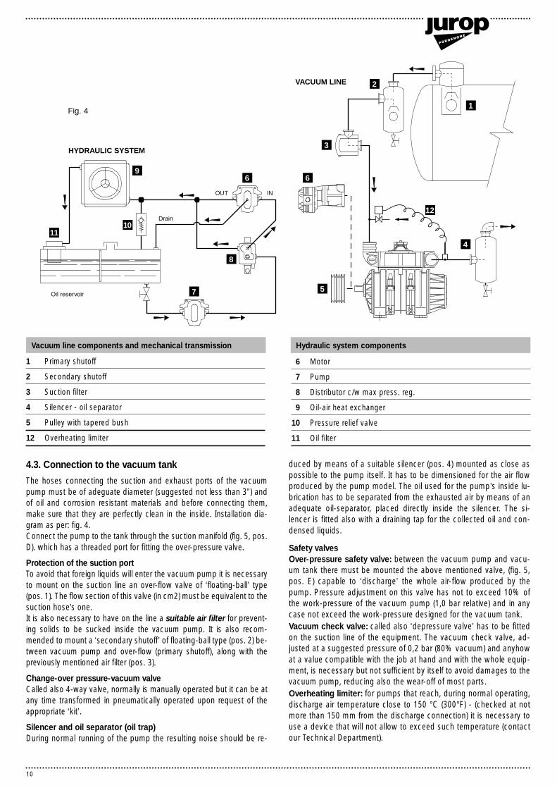
Fig. 4
HYDRAULIC SYSTEM
Drain
INOUT
Oil reservoir
VACUUM LINE
1110
9
8
7 5
6
3
1
2
4
6
12
1 Primary shutoff
2 Secondary shutoff
3 Suction filter
4 Silencer - oil separator
5 Pulley with tapered bush
12 Overheating limiter
6 Motor
7 Pump
8 Distributor c/w max press. reg.
9 Oil-air heat exchanger
10 Pressure relief valve
11 Oil filter
Vacuum line components and mechanical transmission Hydraulic system components
4.3. Connection to the vacuum tank
The hoses connecting the suction and exhaust ports of the vacuumpump must be of adeguate diameter (suggested not less than 3”) andof oil and corrosion resistant materials and before connecting them,make sure that they are perfectly clean in the inside. Installation dia-gram as per: fig. 4.Connect the pump to the tank through the suction manifold (fig. 5, pos.D). which has a threaded port for fitting the over-pressure valve.
Protection of the suction portTo avoid that foreign liquids will enter the vacuum pump it is necessaryto mount on the suction line an over-flow valve of ‘floating-ball’ type(pos. 1). The flow section of this valve (in cm2) must be equivalent to thesuction hose’s one. It is also necessary to have on the line a suitable air filter for prevent-ing solids to be sucked inside the vacuum pump. It is also recom-mended to mount a ‘secondary shutoff’ of floating-ball type (pos. 2) be-tween vacuum pump and over-flow (primary shutoff), along with thepreviously mentioned air filter (pos. 3).
Change-over pressure-vacuum valveCalled also 4-way valve, normally is manually operated but it can be atany time transformed in pneumatically operated upon request of theappropriate ‘kit’.
Silencer and oil separator (oil trap)During normal running of the pump the resulting noise should be re-
duced by means of a suitable silencer (pos. 4) mounted as close aspossible to the pump itself. It has to be dimensioned for the air flowproduced by the pump model. The oil used for the pump’s inside lu-brication has to be separated from the exhausted air by means of anadequate oil-separator, placed directly inside the silencer. The si-lencer is fitted also with a draining tap for the collected oil and con-densed liquids.
Safety valvesOver-pressure safety valve: between the vacuum pump and vacu-um tank there must be mounted the above mentioned valve, (fig. 5,pos. E) capable to ‘discharge’ the whole air-flow produced by thepump. Pressure adjustment on this valve has not to exceed 10% ofthe work-pressure of the vacuum pump (1,0 bar relative) and in anycase not exceed the work-pressure designed for the vacuum tank.Vacuum check valve: called also ‘depressure valve’ has to be fittedon the suction line of the equipment. The vacuum check valve, ad-justed at a suggested pressure of 0,2 bar (80% vacuum) and anyhowat a value compatible with the job at hand and with the whole equip-ment, is necessary but not sufficient by itself to avoid damages to thevacuum pump, reducing also the wear-off of most parts.Overheating limiter: for pumps that reach, during normal operating,discharge air temperature close to 150 °C (300°F) - (checked at notmore than 150 mm from the discharge connection) it is necessary touse a device that will not allow to exceed such temperature (contactour Technical Department).
Fig. 4

11
21
Fig. 6
Exhaust
Vacuum-pressure manifold
Drip oilers
Suction
Pressure relief valve port. (Available for PNR-PNE 102-122-142 only if foreseen with additional conveyor Ref. no.1627102500)
Vanes inspection port
Gear box oil filling plug
Gear box oil level plug
Air injection valves (PNR version)
Oil tank
Oil filling port and dip stickM
L
I
H
G
F
E
D
C
B
A
A
C
B
H
M
L
IG
F
E
D
5. Starting-up instructions Fig. 5
5.1. Oil level checkingBefore starting the equipment check the lubri-cating oil level of the pump by means of theproper dip stick. Check also the oil level in thegearbox (models M).
5.2. Starting-up of the pump• Open all the valves on the vacuum line.• Start slowly, and for a short time, the vacu-um pump. Check that the rotation direction iscorrect.
ATTENTION: a wrong rotation direction will cause the breackage ofthe vanes! Check also the correct working and the position of the 4-way valve!
Transmission Handle position Running withDirect drive LH 1 PressureGearbox dr. RH 2 VacuumDirect drive RH 1 VacuumGearbox dr. LH 2 Pressure
Lefthand rot. means counterclockwise and righthand rot. clockwise,looking at the drive shaft of the pump.
• Check the lubrication of the pump: oil drops have to fall regularyand constantly inside the oilers. The automatic lubrication pump iscorrectly adjusted before delivery of the vacuum pump and, normal-ly, does not require any further adjustment. See part 7.1.3.(Lubrica-tion adjustment) if a changement has to be done.
Normally the conveyor/manifold with the threadedconnection for the over-pressure valve is fitted onthe front of the pump. It can however be moved, if
needed, towards the rear.). In this case the function vacuum-pressure will be opposite of the described one.

12
6. Running of the pump
Starting-up: it is recommended a smooth starting without any suddenacceleration in order to avoid damages to the pump and its drive.
Stopping: when the pump is driven by an auxiliary engine disengagethe transmission before stopping it.
Take care :• Do not obstruct or tamper with the safety valves.• Do not sprinkle water or other liquids on the pump while running.• Do not exceed temperature of 150 °C (300 °F) measured at the airdischarge connection.• Work speed: once that the wanted vacuum rated has been attainedit is recommandable to decrease the RPM. This usefull procedure, thatwill not increase the time requested to fill up the tank, will hoever resultin a lesser wear of the vanes. It is suggested to reduce the speed alsowhen operating with pressure.• Anyway, always run the pump at the indicated (see also on thepump’s tag) RPM possibly without going under the minimum speed, inorder to avoid abnormal wear of the pump housing.• In the eventuality that the suction - exhaust line has some kind ofobstruction, stop immediately the pump and remove the obstructionand/or its cause.• The air flow and the vacuum rate inside the tank has to be adjustedby means of the vacuum pump RPM only (not by any other means likevalves etc).
• After long stillstanding periods or after working in rather dusty envi-ronment and in the eventuality that foreign liquids have been suckedinside the pump, the insides of the pump have to be washed. This op-eration to be carried out when the pump has cooled down: by runningthe pump very slowly, introduce through the suction port, about 1,5litres of diesel fuel. This liquid has to be removed from the insides oncethat the washing operation has been completed. Plenty of oil (see point2.4) must be introduced in order to lubricate again the pump.• With temperature below 5 °C (40 °F) and long periods of inactivity,introduce some quantity of oil through the suction connection beforestarting off the pump.• The air injection cooling system grants the use of the vacuum pumpat high vacuum rates. Anyway it has to be remembered that the pumphas been designed for non-continuous work. This cooling system al-lows to dissipate part of the accumulated heat still at satisfactory lu-brication conditions. Continuous, heavy-duty work, or prolonged workperiods will cause an over-heating of the pump, consequently reduc-ing performances and durability.• With the PNR models it is quite normal that the vacuum rate in thetank will fall down at about 50%, if and when the pump is stopped forsufficient time. This because atmosferic air will flow back in the tankthrough the injection valves, which are adjusted at approximately 0,5bar. Vent the tank and take it to atmospheric pressure when stoppingthe pump in order to avoid back rotation of the pump.
7.1. Ordinary maintenance
Suggested periodical checking in order to maintain a good efficiencyof the pump
7.1.1. Periodical checking• Check the regular dropping of the oil inside the oilers. Prescribedoil quantity as per part. 2.3.• Clean regulary the filters on the air injection ports (see fig. 5) andthe filter placed on the oil block (see fig. B).• Check the drive elements, according to the manufacturerprescriptions.• Check the oil level in the gearbox (-M- models).• Drain the oil from the silencer. Do not use it again on the vacuumpump.
Furthermore check this, with the following frequency:
Unit Daily Weekly Quarterly
Lubricating oil level •
Pressure andvacuum •
Safetyvalves •
Air filter cleaning •
Vaneswear •
• The oil level has to stay above the minimum mark of the dip stick oth-erwise the pump will not suck any oil. This will cause quick wear of thevacuum pump and seize the oil pump. Periodically clean also the oilpump filter and the oil tank.• Decreasing performances (vacuum rate and maximum pressure)indicate clearly a wear-off of some components. Therefore check thevanes without further delay.• In any case the vanes have to be checked at least every threemonths.
For particulary heavy duty working conditions (highvacuum rates, dusty environment, long working times) do thecheckings more frequently than indicated in the maintenancechart.
NOTE
7. Maintenance
Fig. B
13
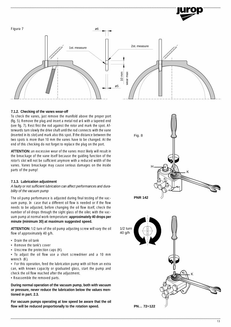
wea
r m
ax
1st. measure 2st. measure
10 m
m
ø6
ø5
Figura 7
7.1.2. Checking of the vanes wear-offTo check the vanes, just remove the manifold above the proper port(fig. 5). Remove the plug and insert a metal rod ø 6 with a tapered end(see fig. 7). Rest first the rod against the rotor and mark the spot. Af-terwards turn slowly the drive shaft until the rod connects with the vane(inserted in its slot) and mark also this spot. If the distance between thetwo spots is more than 10 mm the vanes have to be changed. At theend of this checking do not forget to replace the plug on the port.
ATTENTION: an excessive wear of the vanes most likely will result inthe breackage of the vane itself because the guiding function of therotor’s slot will not be sufficient anymore with a reduced width of thevanes. Vanes breackage may cause serious damages on the insideparts of the pump!
7.1.3. Lubrication adjustmentA faulty or not sufficient lubrication can affect performances and dura-bility of the vacuum pump
The oil pump performance is adjusted during final testing of the vac-uum pump. In case that a different oil flow is needed or if the flowneeds to be adjusted, before changing the oil flow itself, check thenumber of oil drops through the sight glass of the oiler, with the vac-uum pump at normal work-temperature: approximately 40 drops perminute (minimum 30) at maximum suggested speed.
ATTENTION: 1/2 turn of the oil pump adjusting screw will vary the oilflow of approximately 40 g/h.
• Drain the oil tank• Remove the tank’s cover• Unscrew the protection caps (H).• To adjust the oil flow use a short screwdriver and a 10 mm wrench (K).• For this operation, feed the lubrication pump with oil from an extracan, with known capacity or graduated glass, start the pump andcheck the oil flow reached after the adjustment.• Reassemble the removed parts.
During normal operation of the vacuum pump, both with vacuumor pressure, never reduce the lubrication below the values men-tioned in part. 2.3.
For vacuum pumps operating at low speed be aware that the oilflow will be reduced proportionally to the rotation speed.
K
H
K
Fig. 8
PNR 142
PN… 72÷122
1/2 turn40 g/h

14
3
4
8
10
5
9
2
6
1 7
Fig. 9
• Reassemble everything again in the right sequence, absolutelyavoiding to leave foreign parts inside the pump.• Always change also all the gaskets and the O-rings after havingthem properly lubricated and also the seal (pos. 11), if necessary. Putsome grease in the space between the bearing (pos. 10) and theflange(pos. 8).• Reassemble the oil tank (pos. 6) and the O-ring (pos. 7) carefullyinserting the drive shaft without damaging the seal. Insert correctlythe lubrication pump in the driving slot and refit the flange. Re-assemble the lubrication pipes and the tank’s cap (pos. 2) and thegasket (pos. 3); replace the plug on the tank and refill it with lubrica-tion oil.
ATTENTION:• On direct drive models (D) normally it is not necessary to removethe front small flange. However, if this has to be done do not forgetto grease the underneath bearing.• The front bearing (on D models) has been greased during the
pump’s assemblying. Lubrication of said bearing is necessary afterlong working periods only (for example, normal duration of a set ofvanes). It is consequently suggested to pump carefully new greasethrough the lubrication nipple in order to avoid damages to the seals.• When changing the vanes do not forget to carefully clean all thecomponents that you have dismantled (filters, tank, pump etc)
Cleaning of the inside exhaust port of the pump housingand the 4-way manifolds.Frequency: at every changing of the vanes.How to proceed: Dismantle the manifold and remove possible oil-scales or other foreign parts. The clogging-up of this manifold andthe exaust port depends mainly from heavy duty use of the pump andcauses an increase of temperature and a non perfect closing of thecheck valve. A careful cleaning of all components, including the in-sides of the housing and the non-return check valve and it’s seat, istherefore strongly recommended.
NOTE
7.2. Extraordinary maintenance - changing of the vanesTo be done when the vanes wear has reached the mentioned 10 mm
• It is suggested to remove the oil tank on the rear part becausegenerally the pump’s drive components are fitted on the front flange.• Use always the specific kit of gaskets for the pump model at hand(see also spare parts list)• Drain the oil tank through the proper port (pos.1).
• Remove the tank’s cap (pos.2) and change the gasket (pos.3). Unscrew the lubrication pipe’s fittings connecting the oil pump to theoilers (pos. 4).• Remove the oil pump. • Remove the screws fixing the oil tank (pos. 6) and carefully removeit, eventually using two screws partially winded inside the threads.Avoid that the rotor falls down inside the housing, supporting it ifnecessary with adequate tools.• Change the O-Ring (pos. 7).• Remove the pump’s flange (pos. 8), the ring (pos. 9) and the bear-ing (pos. 10). This will make the reassembly of the oil tank (pos. 6)much easier.• Lubricate the new vanes before inserting them in the rotor’s slots.
ATTENTION: the new vanes have to be inserted with the roundedcorner facing towards the housing (see also fig. 9a).
Fig. 9a
4

15
8. Trouble-shooting : causes and remedies
TROUBLES
Overheating of the pump
Cause Remedies
• Faulty lubrication • Check the oil pump
• Missing oil • Fill up the oil tank
• Revolutions to high • Reduce the Rpm
• Operating time too long at too high vacuum rate • Decrease the vacuum rate
• Clogged filters on the air injection system • Clean the filters
• Exhaust port, check valve partly clogged • Remove crusts and scales
• Insufficient diameter of vacuum and discharge line • Check the correct dimensions of the line (minimum suggested 3”)
The pump is blocked
Cause Remedies
• Brocken vanes: • Dismantle the pump and change the vanes
- due to foreign parts • Check/clean the filters and elements on the vacuum line
- due to faulty lubrication • Check the lubrication pump
• Frozen up pump • Warm-up the pump
• Damaged drive system • Change the damaged parts
Reduced performances of the vacuum pump (max. vacuum rate, max. pressure, air flow)
Cause Remedies
• 4-way valve handle in neutral position • Move the handle against the resting pin
• Worn vanes • Change the vanes
• Leaking check valve • Clean the check valve
• Worn O-rings • Change the seals
• Leaking gaskets and/or valves on the vacuum tank • Change that damaged parts
• Clogged connecting pipeline • Change the damaged hoses - pipes
• Floating ball or air filter obstructed • Dismantle and clean
• Crusted up exhaust manifold • Dismantle and clean
• Vacuum line components under-dimensioned • Check the dimensioning for the pump model at hand
• Rubber connection obstructed or damaged • Change the connections
Abnormal oil consumption
Cause Remedies
• Insufficient lubrication • Adjust the oil pump flow (see par. 7.1.3)
• Excessive oil consumption • Loss of adjustment of the oil pump• Probable wear or breakage of the seal rings of the vacuum pump
shaft. Replace them• Check the fittings built on the automatic oil pump and screw tight
WARRANTYA total compliance with the instructions contained in this booklet, concerning running and maintenance of the pump, is mandatory to havegranted the manufacturer’s warranty conditions on faulty parts.The Seller warrants the pump against defects in workmanship or material under normal and proper use and installation, excluded the lubri-cants, the parts subjected to wear and the parts damaged by improper use or inadequate maintenance.

H12
H11
H13
H14
H15
H16
H17
23
76
76
57 2 36 88
57 2 36
76
89
87
PN
E82
PN
R72
PN
E72
PN
R82
PN
R82
8180
8180
8180
PN
E82
721
78
6672
60-6
1
6473 79 35 56
40
10 70
64
11
45
3 P
NR
82 P
NE
46
68
71
3749
14
12
47
69
7364
16
53
25
4255
73
5341
54
19
48
15
6
514436473
64 73
38
64 73
17-1
8
73
20
65
58
6473
78
6371
63
24 75
55
50
54
1359
69
74
26
39
70
8
52
58
9
59
7364
H4
H3
H8
H2
H6
16
H1
H7
H8
H9
H10
H5
PN
.....H
DR
A
9.1.
Mod
.PN
R-P
NE
72-
82D
22
6283
85
86
1 44 5
32-3
431-3
377
77
28-3
0
27-2
9
77
A
67
92
84 9190
93
16
9. Parts list layout
9.1. Mod. PNR-PNE 72-82 D

17
Pos. Code Description Quantity
1 1401200700 Oil dripper automatic lubrication 22 1493300200 Air injection valve PNR 72 1
1493300200 Air injection valve PNR 82 23 1601605700 Vane PNR 72 5
1601605800 Vane PNR 82 54 1605500000 Handle R-PNR-PNE 15 1508100000 Distributor PR-PNR-PNE 16 1608501700 Conveyor PNR-PNE 72-82 17 1610100000 Turning conveyor flange 18 1610500400 Flange R-PNR-PNE 72-82 D 19 1610508400 Flange PNR-PNE 72-82 D 110 1610508500 Automatic lubrication pump flange R-PNR-PNE 111 1612503300 Oil tank PNR-PNE 72-82 112 1621503300 Rotor PNR-PNE 72 1
1621503400 Rotor PNR-PNE 82 113 1622002600 Shaft M10 114 1622007800 Check valve shaft PNR-PNE 72-82-102-122 115 1623100000 Conveyor cap PNR-PNE 72-82 116 1626001300 Bushing PNR-PNE 72-82 D 117 1627100200 Conveyor Ø76 with safety valve connection 118 1627100300 Conveyor Ø80 with safety valve connection 119 1627100500 Turning conveyor Ø76 120 1627504300 Manifold PNR-PNE 72-82 121 1640101100 Oil tank cap PNR-PNE 72-82 122 1642600100 Drive shaft protection 123 1642600000 Pipeline protection 324 1650014100 Front splined shaft PNR-PNE 72-82 D 125 1650014200 Front smooth shaft PNR-PNE 72-82 D 126 1650014300 Rear shaft PNR-PNE 72-82 127 1663036400 Front lubricating line PNR-PNE 72 D lh/M rh 1
1663037600 Front lubricating line PNR-PNE 82 D lh/M rh 128 1663036500 Rear lubricating line PNR-PNE 72 D lh/M rh 1
1663037700 Rear lubricating line PNR-PNE 82 D lh/M rh 129 1663036800 Front lubricating line PNR-PNE 72 D rh/M lh 1
1663038000 Front lubricating line PNR-PNE 82 D rh/M lh 130 1663036900 Rear lubricating line PNR-PNE 72 D rh/M lh 1
1663038100 Rear lubricating line PNR-PNE 82 D rh/M lh 131 1663037000 External oil dripper line PNR-PNE 72 D lh/M rh 1
1663038300 External oil dripper line PNR-PNE 82 D lh/M rh 132 1663037100 Internal oil dripper line PNR-PNE 72 D lh/M rh 1
1663038200 Internal oil dripper line PNR-PNE 82 D lh/M rh 133 1663037200 External oil dripper line PNR-PNE 72 D rh/M lh 1
1663038400 External oil dripper line PNR-PNE 82 D rh/M lh 134 1663037300 Internal oil dripper line PNR-PNE 72 D rh/M lh 1
1663038500 Internal oil dripper line PNR-PNE 82 D rh/M lh 135 1663041200 Suction line for aut. lubric. pump PNR-PNE 72-82 136 1681007100 Air injection pipes bracket PNR 72 1
1681007000 Air injection pipes bracket PNR 82 137 1680608800 Manifold gasket PNR-PNE 72-82 138 1680700200 Conveyor gasket PNR-PNE 72-82 139 1680700400 Flange gasket PNR-PNE 72-82 D 140 1680707500 Oil tank cap gasket PNR-PNE 72-82 141 1683600000 Oil stick 142 1684000000 Plug G3/8 143 1685002800 Washer 30x8,5x4 144 1685100000 Alu washer 14x20x1,5 245 1685100200 Alu washer 17x22x1,5 146 1685100800 Alu washer 8x14x1,5 147 1687505800 Housing PNR-PNE 72 1
1687505700 Housing PNR-PNE 82 148 1691000000 Conveyor spring 149 1693500300 Check valve PNR-PNE 72-82 150 4022100010 Greasing nipple M10x1 151 4022200030 Seal 41x27x10 152 4022200040 Seal 72x40x10 153 4022200111 Seal 72x48x15 254 4022200307 OR 6287 255 4022200308 OR 4775 256 4022300001 Nylon filter Ø6 157 4022301004 Silencer-filter 3/4" PNR 72 1
4022301004 Silencer-filter 3/4" PNR 82 258 4023100040 Bearing 6308 2
Pos. Code Description Quantity
59 4023130020 Bushing 48x40x22 260 4024251000 Automatic lubricating pump (cw rotation) 161 4024251500 Automatic lubricating pump (ccw rotation) 162 4026101404 Screw M8x12 galvanized 363 4026103003 Screw M12x35 galvanized 464 4026107110 Screw M8x25 4065 4026107117 Screw M8x60 266 4026120304 Screw M6x16 267 4026120300 Screw M6x14 168 4026120400 Screw M8x12 169 1672001600 PNR rotor screw M10 1070 4026300020 Compensation ring Ø90 271 4026350609 Grower washer M12 472 4026350908 Washer M6 273 4026350909 Washer M8 4274 4026414617 Pin 3x40 (*) 175 4026500909 Tab 10x8x50 176 4026701310 Fitting G1/2 PNR 72 1
4026701310 Fitting G1/2 PNR 82 277 4026706000 Fitting 90° Ø4-1/8 678 4026706101 Fitting Ø4-1/8 279 4026706003 Fitting 90° Ø6-1/8 180 4026904001 Plug G1/2 PNR-PNE 72 1
4026904001 Plug G1/2 PNR-PNE 82 281 4026359003 Alu washer 21,5x26x1,5 PNR-PNE 72 1
4026359003 Alu washer 21,5x26x1,5 PNR-PNE 82 282 1601605300 Vane PNE 72 5
1601605400 Vane PNE 82 583 4026356002 Flat washer M8 galvanized 384 4022301001 Oil block filter G 1/4 185 1680609700 Oil pump gasket 186 1680609800 Oil pump flange gasket 187 1563008100 Air injection pipe r. PNR 82 188 1563008200 Air injection pipe l. PNR 82 189 1563008300 Air injection pipe PNR 72 190 4026705702 Oil drain extention 191 4026702502 Oil drain T fitting 192 4026706004 Fitting 90° G1/4 ø6 193 1663042900 Oil drain line PNR 72 D rh 1
1663043000 Oil drain line PNR 72 D lh 11663043100 Oil drain line PNR 82 D rh 11663043200 Oil drain line PNR 82 D lh 1
(*): on models with ccw (left hand) rotation
PNR-PNE 72-82 HDR
Pos. Code Description Quantity
H1 1610005500 Centering flange PNR 72-82 HDR 1H2 1612501000 Bracket PNR-PNE ... HDR 1H3 4026171211 Stud screw M12x80 2H4 4026305508 Nut M12 2H5 1470102900 Coupling PNR 72-82 HDR 1H6 4026350909 Washer M8 3H7 4026107110 Screw M8x25 3H8 4026350609 Grower washer M12 4H9 4026107313 Screw M12x40 2H10 4026171304 Stud screw M14x40 4H11 4026350610 Grower washer M14 4H12 4026300808 Nut M14 4H13 4024107008 Motor PNR-PNE 72-82 HDR 1H14 4026711002 Flange G1 1H15 4026711003 Flange G1 1/4 1H16 4026136004 Dowel pin M8x10 1H17 4026136006 Dowel pin M8x14 1
1892002500 Gaskets kit PNR-PNE 72-82 D 1
Parts list PNR-PNE 72-82 D

4
PN
E82
PN
R72
PN
E72
PN
R82
63
11
45
3 P
NR
84P
NE
46
69
75
37
49
14
12
47
4254
74
41
53
18
7
48
15
6
50436374
1 44 5
6332-3
431-3
379
79
28-3
0
74 38
63 74
16-1
7
27-2
9
7974
19
65
6675
66
53
1359
7024
76
A
21
A
67
94
86 9392
9.2.
Mod
.PN
R-P
NE
72-
82M
95
PN
R82
8382
78
8382
8382
PN
E82
78
80
6773
60-6
1
6374 81 35 55
56 2 36 90
56 2 36
78
91
89
40
9 71
5258
6374
80
87
88
20
54
77
70
59
6352
5871
25
7239
5742 45 10
22
7423
4663
26
5851
6445
45
42
62
74
8
85
18
9.2. Mod. PNR-PNE 72-82 M

19
Pos. Code Description Quantity
1 1401200700 Oil dripper automatic lubrication 22 1493300200 Air injection valve PNR 72 1
1493300200 Air injection valve PNR 82 23 1601605700 Vane PNR 72 5
1601605800 Vane PNR 82 54 1605500000 Handle R-PNR-PNE 15 1508100000 Distributor PR-PNR-PNE 16 1608501700 Conveyor PNR-PNE 72-82 17 1610100000 Turning conveyor flange 18 1610508300 Flange PNR-PNE 72-82 M 19 1610508500 Automatic lubrication pump flange R-PNR-PNE 110 1612503200 Gearbox PNR-PNE 72-82 M 111 1612503300 Oil tank PNR-PNE 72-82 112 1621503300 Rotor PNR-PNE 72 1
1621503400 Rotor PNR-PNE 82 113 1622002600 Shaft M10 114 1622007800 Check valve shaft PNR-PNE 72-82-102-122 115 1623100000 Conveyor cap PN-PNR-PNE 72-82 116 1627100200 Conveyor Ø76 with safety valve connection 117 1627100300 Conveyor Ø80 with safety valve connection 118 1627100500 Turning conveyor Ø76 119 1627504300 Manifold PNR-PNE 72-82 120 1640101100 Oil tank cap PNR-PNE 72-82 121 1642600000 Pipeline protection 322 1642600100 Drive shaft protection 123 1650014000 Front shaft PNR-PNE 72-82 M 124 1650014300 Rear shaft PNR-PNE 72-82 125 1651005400 Pinion PNR-PNE 72-82 M 126 1651005600 Gear PNR-PNE 72-82 M 127 1663036400 Front lubricating line PNR-PNE 72 D lh/M rh 1
1663037600 Front lubricating line PNR-PNE 82 D lh/M rh 128 1663036500 Rear lubrication line PNR-PNE 72 D lh/M rh 1
1663037700 Rear lubricating line PNR-PNE 82 D lh/M rh 129 1663036800 Front lubricating line PNR-PNE 72 D rh/M lh 1
1663038000 Front lubricating line PNR-PNE 82 D rh/M lh 130 1663036900 Rear lubricating line PNR-PNE 72 D rh/M lh 1
1663038100 Rear lubricating line PNR-PNE 82 D rh/M lh 131 1663037000 External oil dripper line PNR-PNE 72 D lh/M rh 1
1663038300 External oil dripper line PNR-PNE 82 D lh/M rh 132 1663037100 Internal oil dripper line PNR-PNE 72 D lh/M rh 1
1663038200 Internal oil dripper line PNR-PNE 82 D lh/M rh 133 1663037200 External oil dripper line PNR-PNE 72 D rh/M lh 1
1663038400 External oil dripper line PNR-PNE 82 D rh/M lh 134 1663037300 Internal oil dripper line PNR-PNE 72 D rh/M lh 1
1663038500 Internal oil dripper line PNR-PNE 82 D rh/M lh 135 1663041200 Suction line for aut. lubric. pump PNR-PNE 72-82 136 1681007100 Air injection pipes bracket PNR 72 1
1681007000 Air injection pipes bracket PNR 82 137 1680608800 Manifold gasket PNR-PNE 72-82 138 1680700200 Conveyor gasket PNR-PNE 72-82 139 1680707400 Gearbox gasket PNR-PNE 72-82 M 140 1680707500 Oil tank cap gasket PNR-PNE 72-82 141 1683600000 Oil stick 142 1684000000 Plug G3/8 443 1685002800 Washer 30x8,5x4 144 1685100000 Alu washer 14x20x1,5 245 1685100200 Alu washer 17x22x1,5 446 1685100800 Alu washer 8x14x1,5 347 1687505800 Housing PNR-PNE 72 1
1687505700 Housing PNR-PNE 82 148 1691000000 Conveyor spring 1
Pos. Code Description Quantity
49 1693500300 Check valve PNR-PNE 72-82 150 4022200030 Seal 41x27x10 151 4022200040 Seal 72x40x10 152 4022200111 Seal 72x48x15 253 4022200307 OR 6287 254 4022200308 OR 4775 255 4022300001 Nylon filter Ø6 156 4022301004 Silencer-filter 3/4" PNR 72 1
4022301004 Silencer-filter 3/4" PNR 82 257 4023100018 Bearing 6206 158 4023100040 Bearing 6308 359 4023130020 Bushing 48x40x22 260 4024251000 Automatic lubricating pump (cw rotation) 161 4024251500 Automatic lubricating pump (ccw rotation) 162 4026101404 Screw M8x12 galvanized 363 4026107110 Screw M8x25 3764 4026107111 Screw M8x30 765 4026107117 Screw M8x60 266 4026103003 Screw M12x35 galvanized 467 4026120304 Screw M6x16 268 4026120300 Screw M6x14 169 4026120400 Screw M8x12 170 1672001600 PNR rotor screw M10 1071 4026300020 Compensation ring Ø90 272 4026305616 Nut M30x2 173 4026350908 Washer M6 274 4026350909 Washer M8 4475 4026350609 Grower washer M12 476 4026414617 Pin 3x40 (*) 177 4026500905 Tab 10x8x32 178 4026701310 Fitting G1/2 PNR 72 1
4026701310 Fitting G1/2 PNR 82 279 4026706000 Fitting 90° Ø4-1/8 680 4026706101 Fitting Ø4-1/8 281 4026706003 Fitting 90° Ø6-1/8 182 4026904001 Plug G1/2 PNR-PNE 72 1
4026904001 Plug G1/2 PNR-PNE 82 283 4026359003 Alu washer 21,5x26x1,5 PNR-PNE 72 1
4026359003 Alu washer 21,5x26x1,5 PNR-PNE 82 284 1601605300 Vane PNE 72 5
1601605400 Vane PNE 82 585 4026356002 Flat washer M8 galvanized 386 4022301001 Oil block filter G 1/4 187 1680609700 Oil pump gasket 188 1680609800 Oil pump flange gasket 189 1563008100 Air injection pipe r. PNR 82 190 1563008200 Air injection pipe l. PNR 82 191 1563008300 Air injection pipe PNR 72 192 4026705702 Oil drain extention 193 4026702502 Oil drain T fitting 194 4026706004 Fitting 90° G1/4 ø6 195 1663042900 Oil drain line PNR 72 D rh 1
1663043000 Oil drain line PNR 72 D lh 11663043100 Oil drain line PNR 82 D rh 11663043200 Oil drain line PNR 82 D lh 1
(*): on models with cw (right hand) rotation
1892002600 Gaskets kit PNR-PNE 72-82 M 1
Parts list PNR-PNE 72-82 M

20
PN
.....H
DR
A
H17
H18
9.3.
Mod
.PN
R-P
NE
102
-122
D
PN
E
PN
R
PN
R 8584
8584
PN
E
80
57 2 35 94
8093
1 43 5
30-3
331-3
281
81
27-2
9
26-2
8
81
A
69
97
90 9695
98
66
10
44
78
45
70
36 77
48
13
11
46
71
7666
7666
2115
37
73
7
52
59
9
61
24
4154
76
4022
6
6676
66 76 14 39
6699
76
1967
54
42
450
4979
23
76
3 P
NR
86 P
NE
1260
7125
51
H13
H4
H3
H8
H12
H11
H2
H6
15
H1
H7
H8
H9
H10 H5
H12
H11
H14
H15
H16
PN
R 1
02 H
DR
PN
E 1
02 H
DR
PN
R 1
22 H
DR
PN
E 1
22 H
DR
74
65
100
77
6489
82
6875
62-6
3
6676 83 34 56
38
8 72
5358
6676
82
91
92
101
77
55
16
16-1
7-18
77
88
47
77
87
5565
100
102
99
55
102
77
101
20
9.3. Mod. PNR-PNE 102-122 D

21
Pos. Code Description Quantity
1 1401200700 Oil dripper automatic lubrication 22 1493300200 Air injection valve PNR 23 1601605900 Vane PNR 102 5
1601606000 Vane PNR 122 54 1605500000 Handle R-PNR-PNE 15 1508100000 Distributor PR-PNR-PNE 16 1608501800 Conveyor PNR-PNE 102-122 17 1610508200 Flange R-PNR-PNE 102-122-142 D 18 1610508500 Automatic lubrication pump flange R-PNR-PNE 19 1610508600 Flange PNR-PNE 102-122 D 110 1612503400 Oil tank PNR-PNE 102-122 111 1621503500 Rotor PNR-PNE 102 1
1621503600 Rotor PNR-PNE 122 112 1622002600 Shaft M10 113 1622007800 Check valve shaft PNR-PNE 72-82-102-122 114 1623100500 Conveyor cap PN-PNR-PNE 102-122 115 1626001100 Bushing PNR-PNE 102-122 D 116 1627102400 Conveyor ø 100 1-217 1627102700 Conveyor ø 80 118 1627102800 Conveyor ø 76 119 1627504400 Manifold PNR-PNE 102-122 120 1640101200 Oil tank cap PNR-PNE 102-122 121 1642600100 Drive shaft protection 122 1642600000 Pipeline protection 323 1650014600 Front splined shaft PNR-PNE 102-122 D 124 1650014700 Front smooth shaft PNR-PNE 102-122 D 125 1650014800 Rear shaft PNR-PNE 102-122 126 1663038800 Front lubricating line PNR-PNE 102 D lh/M rh 1
1663040000 Front lubricating line PNR-PNE 122 D lh/M rh 127 1663038900 Rear lubricating line PNR-PNE 102 D lh/M rh 1
1663040100 Rear lubricating line PNR-PNE 122 D lh/M rh 128 1663039200 Front lubricating line PNR-PNE 102 D rh/M lh 1
1663040400 Front lubricating line PNR-PNE 122 D rh/M lh 129 1663039300 Rear lubricating line PNR-PNE 102 D rh/M lh 1
1663040500 Rear lubricating line PNR-PNE 122 D rh/M lh 130 1663039400 Internal oil dripper line PNR-PNE 102 D lh/M rh 1
1663040600 Internal oil dripper line PNR-PNE 122 D lh/M rh 131 1663039500 External oil dripper line PNR-PNE 102 D lh/M rh 1
1663040700 External oil dripper line PNR-PNE 122 D lh/M rh 132 1663039600 External oil dripper line PNR-PNE 102 D rh/M lh 1
1663040800 External oil dripper line PNR-PNE 122 D rh/M lh 133 1663039700 Internal oil dripper line PNR-PNE 102 D rh/M lh 1
1663040900 Internal oil dripper line PNR-PNE 122 D rh/M lh 134 1663041100 Suction line for aut. lubric. pump PNR-PNE 102-122 135 1681006900 Air injection pipes bracket PNR 122 1
1681007000 Air injection pipes bracket PNR 102 136 1680608900 Manifold gasket PNR-PNE 102-122 137 1680707300 Flange gasket PNR-PNE 102-122-142 D 138 1680707700 Oil tank gasket PNR-PNE 102-122 139 1680707800 Conveyor gasket PNR-PNE 102-122 140 1683600300 Oil stick 141 1684000000 Plug G3/8 142 1685002800 Washer 30x8,5x4 143 1685100000 Alu washer 14x20x1,5 244 1685100200 Alu washer 17x22x1,5 145 1685100800 Alu washer 8x14x1,5 146 1687505900 Housing PNR-PNE 102 1
1687506000 Housing PNR-PNE 122 147 1691000000 Conveyor spring 148 1693500400 Check valve PNR-PNE 102-122 149 4022100010 Greasing nipple M10x1 150 4022200030 Seal 41x27x10 151 4022200113 Seal 70x55x15 152 4022200044 Seal 65x45x8 153 4022200111 Seal 72x48x15 154 4022200309 OR 4875 255 4022200310 OR 6362 2(3)56 4022300001 Nylon filter Ø6 157 4022301004 Silencer-filter 3/4" 258 4023100040 Bearing 6308 159 4023100046 Bearing 6309 160 4023130020 Bushing 48x40x22 161 4023130035 Bushing 55x45x22 1
Pos. Code Description Quantity
62 4024251000 Automatic lubricating pump (cw rotation) 163 4024251500 Automatic lubricating pump (ccw rotation) 164 4026101404 Screw M8x12 galvanized 365 4026102807 Screw M8x25 galvanized (4)66 4026107110 Screw M8x25 4067 4026107117 Screw M8x60 268 4026120304 Screw M6x16 269 4026120300 Screw M6x14 170 4026120400 Screw M8x12 171 1672001600 PNR rotor screw M10 1072 4026300020 Compensation ring Ø90 173 4026300025 Compensation ring Ø100 174 1681006800 Plate vac-press PNR-PNE 102-122 175 4026350908 Washer M6 276 4026350909 Washer M8 4277 4026350606 Grower washer M8 8(12)78 4026414617 Pin 3x40 (*) 179 4026501006 Tab 12x8x56 180 4026701310 Fitting G1/2 281 4026706000 Fitting 90° Ø4-1/8 682 4026706101 Fitting Ø4-1/8 283 4026706003 Fitting 90° Ø6-1/8 184 4026904001 Plug G1/2 285 4026359003 Alu washer 21,5x26x1,5 286 1601605500 Vane PNE 102 5
1601605600 Vane PNE 122 587 1627102500 Conveyor with safety valve connection (1)88 1627102600 Conveyor (1)89 4026356002 Flat washer M8 galvanized 390 4022301001 Oil block filter G 1/4 191 1680609700 Oil pump gasket 192 1680609800 Oil pump flange gasket 193 1563007900 Air injection pipe r. 194 1563008000 Air injection pipe l. 195 4026705702 Oil drain extention 196 4026702502 Oil drain T fitting 197 4026706004 Fitting 90° G1/4 ø6 198 1663043300 Oil drain line PNR 102 D rh 1
1663043400 Oil drain line PNR 102 D lh 11663043500 Oil drain line PNR 122 D rh 11663043600 Oil drain line PNR 122 D lh 1
99 1610101100 Conveyor flange 2100 4026102801 Screw TE 8.8 M8x35 8101 4026102810 Screw TE 8.8 M8x40 (4)102 4026308005 Nut M8 (4)
(*): on models with ccw (left hand) rotation
PNR-PNE 102-122 HDR
Pos. Code Description Quantity
H1 1610021600 Centering flange PNR-PNE 102-122-142 HDR 1H2 1612501000 Bracket PNR-PNE ... HDR 1H3 4026171211 Stud screw M12x80 2H4 4026305508 Nut M12 2H5 1470102300 Coupling PNR 102-122-142 HDR 1H6 4026350909 Washer M8 3H7 4026120403 Screw M8x20 3H8 4026350609 Grower washer M12 4H9 4026107313 Screw M12x40 2H10 4026171304 Stud screw M14x40 4H11 4026350610 Grower washer M14 4H12 4026300808 Nut M14 4H13 4024107001 Motor PNR-PNE 122 HDR 1H14 4024107009 Motor PNR-PNE 102 HDR 1H15 4026711003 Flange G1 1/4 1H16 4026711004 Flange G1 1/2 1H17 4026136003 Dowel pin M8x8 1H18 4026136006 Dowel pin M8x14 1
1892002700 Gaskets kit PNR-PNE 102-122 D 1
Parts list PNR-PNE 102-122 D
Note: between brackets quantity referred to the conveyor with safety valve connection built.

A
PN
E
PN
R
PN
R 8685
8685
PN
E
81
56 2 35 96
8195
1 43 5
30-3
331-3
282
82
27-2
9
26-2
8
82
A
67
9992 9897
100
66 76
101
65
102
78
103
78
5454
15
54
78
89
104
36 7818
78
8854
65
102
101
104
78
103
72
61
53
66
50
5974
24
75
37
5741
4410
21
77
22
4566
25
5851
6744
44
41
6477
8
80
66
9
44
79
45
71
48
13
11
46
4153
77
4020
47
6
6677
66 77 14 39
15-1
6-17
68
42
449
77
3 P
NR
87 P
NE
1260
7223
19
83
6976
62-6
3
6677 84 34 55
38
7
73
66 77
83
93
94
90
91
9.4.
Mod
.PN
R-P
NE
102
-122
M
5852
22
9.4. Mod. PNR-PNE 102-122 M

23
Pos. Code Description Quantity
1 1401200700 Oil dripper automatic lubrication 22 1493300200 Air injection valve PNR 23 1601605900 Vane PNR 102 5
1601606000 Vane PNR 122 54 1605500000 Handle R-PNR-PNE 15 1508100000 Distributor PR-PNR-PNE 16 1608501800 Conveyor PNR-PNE 102-122 17 1610508500 Automatic lubrication pump flange R-PNR-PNE 18 1610508700 Flange PNR-PNE 102-122 M 19 1612503400 Oil tank PNR-PNE 102-122 110 1612503500 Gearbox PNR-PNE 102-122 M 111 1621503500 Rotor PNR-PNE 102 1
1621503600 Rotor PNR-PNE 122 112 1622002600 Shaft M10 113 1622007800 Check valve shaft PNR-PNE 72-82-102-122 114 1623100500 Conveyor cap PN-PNR-PNE 102-122 115 1627102400 Conveyor Ø 100 1-216 1627102700 Conveyor Ø 80 117 1627102800 Conveyor Ø 76 118 1627504400 Manifold PNR-PNE 102-122 119 1640101200 Oil tank cap PNR-PNE 102-122 120 1642600000 Pipeline protection 321 1642600100 Drive shaft protection 122 1650014500 Front shaft PNR-PNE 102-122 M 123 1650014800 Rear shaft PNR-PNE 102-122 124 1651005500 Pinion PNR-PNE 102-122 M 125 1651005700 Gear PNR-PNE 102-122 M 126 1663038800 Front lubricating line PNR-PNE 102 D lh/M rh 1
1663040000 Front lubricating line PNR-PNE 122 D lh/M rh 127 1663038900 Rear lubricating line PNR-PNE 102 D lh/M rh 1
1663040100 Rear lubricating line PNR-PNE 122 D lh/M rh 128 1663039200 Front lubricating line PNR-PNE 102 D rh/M lh 1
1663040400 Front lubricating line PNR-PNE 122 D rh/M lh 129 1663039300 Rear lubricating line PNR-PNE 102 D rh/M lh 1
1663040500 Rear lubricating line PNR-PNE 122 D rh/M lh 130 1663039400 Internal oil dripper line PNR-PNE 102 D lh/M rh 1
1663040600 Internal oil dripper line PNR-PNE 122 D lh/M rh 131 1663039500 External oil dripper line PNR-PNE 102 D lh/M rh 1
1663040700 External oil dripper line PNR-PNE 122 D lh/M rh 132 1663039600 External oil dripper line PNR-PNE 102 D rh/M lh 1
1663040800 External oil dripper line PNR-PNE 122 D rh/M lh 133 1663039700 Internal oil dripper line PNR-PNE 102 D rh/M lh 1
1663040900 Internal oil dripper line PNR-PNE 122 D rh/M lh 134 1663041100 Suction line for aut. lubric. pump PNR-PNE 102-122 135 1681006900 Air injection pipes bracket PNR 122 1
1681007000 Air injection pipes bracket PNR 102 136 1680608900 Manifold gasket PNR-PNE 102-122 137 1680707600 Gearbox gasket PNR-PNE 102-122 M 138 1680707700 Oil tank gasket PNR-PNE 102-122 139 1680707800 Conveyor gasket PNR-PNE 102-122 140 1683600300 Oil stick 141 1684000000 Plug G3/8 442 1685002800 Washer 30x8,5x4 143 1685100000 Alu washer 14x20x1,5 244 1685100200 Alu washer 17x22x1,5 445 1685100800 Alu washer 8x14x1,5 346 1687505900 Housing PNR-PNE 102 1
1687506000 Housing PNR-PNE 122 147 1691000000 Conveyor spring 148 1693500400 Check valve PNR-PNE 102-122 149 4022200030 Seal 41x27x10 150 4022200113 Seal 70x55x15 1
Pos. Code Description Quantity
51 4022200040 Seal 72x40x10 152 4022200111 Seal 72x48x15 153 4022200309 OR 4875 254 4022200310 OR 6362 2(3)55 4022300001 Nylon filter Ø6 156 4022301004 Silencer-filter 3/4" 257 4023100018 Bearing 6206 158 4023100040 Bearing 6308 259 4023100046 Bearing 6309 160 4023130020 Bushing 48x40x22 161 4023130035 Bushing 55x45x22 162 4024251000 Automatic lubricating pump (cw rotation) 163 4024251500 Automatic lubricating pump (ccw rotation) 164 4026101404 Screw M8x12 galvanized 365 4026102807 Screw M8x25 galvanized (4)66 4026107110 Screw M8x25 3767 4026107111 Screw M8x30 768 4026107117 Screw M8x60 269 4026120304 Screw M6x16 270 4026120300 Screw M6x14 171 4026120400 Screw M8x12 172 1672001600 PNR rotor screw M10 1073 4026300020 Compensation ring Ø90 174 4026300025 Compensation ring Ø100 175 4026306115 Nut M36x3 176 4026350908 Washer M6 277 4026350909 Washer M8 4478 4026350606 Grower washer M8 8(12)79 4026414617 Pin 3x40 (*) 180 4026501003 Tab 12x8x40 181 4026701310 Fitting G1/2 282 4026706000 Fitting 90° Ø4-1/8 683 4026706101 Fitting Ø4-1/8 284 4026706003 Fitting 90° Ø6-1/8 185 4026904001 Plug G 1/2 286 4026359003 Alu washer 21,5x26x1,5 287 1601605500 Vane PNE 102 5
1601605600 Vane PNE 122 588 1627102500 Conveyor with safety valve connection (1)89 1627102600 Conveyor (1)90 1681006800 Plate vac-press PNR-PNE 102-122 191 4026356002 Flat washer M8 galvanized 392 4022301001 Oil block filter G 1/4 193 1680609700 Oil pump gasket 194 1680609800 Oil pump flange gasket 195 1563007900 Air injection pipe r. 196 1563008000 Air injection pipe l. 197 4026705702 Oil drain extention 198 4026702502 Oil drain T fitting 199 4026706004 Fitting 90° G1/4 ø6 1100 1663043300 Oil drain line PNR 102 D rh 1
1663043400 Oil drain line PNR 102 D lh 11663043500 Oil drain line PNR 122 D rh 11663043600 Oil drain line PNR 122 D lh 1
101 1610101100 Conveyor flange 2102 4026102801 Screw TE 8.8 M8x35 8103 4026102810 Screw TE 8.8 M8x40 (4)104 4026308005 Nut M8 (4)
(*): on models with cw (right hand) rotation
1892002800 Gaskets kit PNR-PNE 102-122 M 1
Parts list PNR-PNE 102-122 M
Note: between brackets quantity referred to the conveyor with safety valve connection built.

85
30-3
5
31-3
6
34-4
0
32-3
8
33-3
9
86
5195
95
670
106
105
104
2683
85
H7
H13
H12
H6
H8
H3
H4
H11
H2
H10
H1
H5
29-3
7
24
47
55
12
7
66 80 49
5
1473
54
42
56
6680
91
89
99
72
77
82
60
81
5248
68
68
68
81
81
53
44
108
79
20
13
16
88 78
87
41
10P
NR
142
HD
R
45
6457
946
76
4
11
8
8168
60
6680
58
65
25
72
5027 15
86
62 190
52
48
84
28
74
A
A
H14
H15H9
6910
0
23
9.5.
Mod
. PN
R 1
42 D
101
20
71 108
79
109
79
44
44
17
79
107
110
17-1
8-19
7921
71
110
79
109
44
102 10
3
22
6780
2-3
94 97
94
98 61
8643
92
93
6680
96
5963
75
24
9.5. Mod. PNR 142 D

25
Pos. Code Description Quantity
1 1493300200 Air injection valve PNR 142 22 4024250000 Automatic lubricating pump (cw rotation) 13 4024250500 Automatic lubricating pump (ccw rotation) 14 1601605200 Vane PNR 142 55 1605500100 Handle PNR 142 16 1608100200 Distributor PNR 142 17 1608500700 Conveyor PNR 142 18 1610508100 Flange PNR 142 D 19 1610508200 Flange R-PNR-PNE 102-122-142 D 110 1612500900 Oil tank PNR 142 111 1621503200 Rotor PNR 142 112 1622002500 Check valve shaft PNR 142 113 1622002600 Shaft M10 114 1623500300 Conveyor cap PNR 142 115 1626001100 Bushing PNR 142 D 116 1627501100 Manifold PNR 142 117 1627102400 Conveyor Ø 100 1-218 1627102700 Conveyor Ø 80 119 1627102800 Conveyor Ø 76 120 1610101100 Conveyor Flange 221 1627102500 Conveyor with safety valve connection (1)22 1640101000 Oil tank cap PNR 142 123 1642600100 Drive shaft protection 124 1642600000 Pipeline protection 425 1650012900 Front splined shaft PNR 142 D 126 1650013000 Rear shaft PNR 142 127 1650013100 Front smooth shaft PNR 142 D 128 1663014000 Air injection valve pipe 1/2" PNR 142 229 1663009500 Front lubricating line (housing) PNR 142 D rh/M lh 130 1663016510 Front lubricating line (flange) PNR 142 D rh 131 1663016310 Rear lubricating line PNR 142 D rh/M lh 132 1663034500 Rear oil dripper lubricating line PNR 142 D rh/M lh 133 1663034600 Centering oil dripper lubric. line PNR 142 D rh/M lh 134 1663034700 Front oil dripper lubricating line PNR 142 D rh/M lh 135 1663026010 Front lubricating line (flange) PNR 142 D lh 136 1663016610 Rear lubricating line PNR 142 D lh/M rh 137 1663025700 Front lubricating line (housing) PNR 142 D lh/M rh 138 1663034200 Rear oil dripper lubricating line PNR 142 D lh/M rh 139 1663034300 Centering oil dripper lubric. line PNR 142 D lh/M rh 140 1663034400 Front oil dripper lubricating line PNR 142 D lh/M rh 141 1680608300 Manifold gasket PNR 142 142 1680702500 Conveyor gasket PNR 142 143 1680702700 Oil tank gasket PNR 142 144 4022200310 OR 6362 245 1680703700 Distributor gasket PNR 142 146 1680707300 Flange gasket PNR 142 D 147 1683600300 Oil stick 148 1684000000 Plug G3/8 349 1685002800 Washer 30x8,5x4 150 4026501006 Tab 12x8x56 151 1685100000 Alu washer 14x20x1,5 352 1685100200 Alu washer 17x22x1,5 353 1687501900 Housing PNR 142 D 154 1691000200 Conveyor spring 155 1693500000 Check valve PNR 142 156 4022200030 Seal 41x27x10 157 4022200113 Seal 70x55x15 158 4022200044 Seal 65x45x8 159 4022200111 Seal 72x48x15 160 4022200311 OR 4975 261 4022300001 Nylon filter Ø6 162 4022301004 Silencer-filter 3/4" 263 4023100040 Bearing 6308 164 4023100046 Bearing 6309 165 4023130035 Bushing 55x45x22 166 4026100408 Screw M8x20 1167 4026100410 Screw M8x25 668 4026100510 Screw M10x25 21
Pos. Code Description Quantity
69 4026101409 Screw M8x12 galvanized 370 4026120303 Screw M6x20 271 4026102807 Screw M 8x25 (4)72 1672001600 PNR rotor screw M10 1073 4026120519 Screw M10x110 274 4026155605 Screw M6x16 475 4026300020 Compensation ring Ø90 176 4026300025 Compensation ring Ø100 177 4026322006 Nut M16 178 1685100800 Alu washer 8x14x1,5 179 4026350606 Grower washer M8 8(12)80 4026350909 Washer M8 1781 4026350910 Washer M10 2182 4026414611 Pin 3x24 183 4026414617 Pin 3x40 (*) 184 4026701301 Fitting G1/2 285 4026702000 Fitting Ø4-1/8 486 4026706000 Fitting 90° Ø4-1/8 687 4023130020 Bushing 48x40x22 188 4026120400 Screw M8x12 189 4026350608 Grower washer M10 290 1681006600 Bracket 291 1681005300 Plate vac-press PNR 142 192 4026120304 Screw M6x16 293 4026350908 Washer M6 294 4026706101 Fitting Ø4-1/8 295 1401200700 Oil dripper automatic lubrication 396 1610508500 Automatic lubrication pump flange R-PNR-PNE 197 4026706104 Fitting Ø6-1/8 198 1663041100 Suction line for aut. lubricating pump PNR 102-122-142 199 1672001200 Check valve stop 1100 4026356002 Flat washer M8 galvanized 3101 4022301000 Oil block filter G 1/8 3102 1680609700 Oil pump gasket 1103 1680609800 Oil pump flange gasket 1104 4026910601 Plug G1/8 2105 4026706003 Fitting 90° G1/8 ø6 1106 1663043700 Oil drain line PNR 142 D dx 1
1663043800 Oil drain line PNR 142 D sx 1107 1627102600 Conveyor (1)108 4026102801 Screw M8x35 8109 4026102810 Screw M8x40 (4)110 4026308005 Nut M8 (4)
(*): on models with ccw (left hand) rotation
PNR 142 HDR
Pos. Code Description Quantity
H1 4026350610 Grower washer M14 4H2 1470102300 Coupling PNR 102-122-142 HDR 1H3 1610021600 Centering flange PNR-PNE 102-122-142 HDR 1H4 1612501000 Bracket PNR-PNE ... HDR 1H5 4024107004 Motor PNR 142 HDR 1H6 4026107313 Screw M12x40 2H7 4026120403 Screw M8x20 3H8 4026171211 Stud screw M12x80 2H9 4026171304 Stud screw M14x40 4H10 4026308008 Nut M14 galvanized 4H11 4026305508 Nut M12 2H12 4026350609 Washer grower M12 2H13 4026350909 Washer M8 3H14 4026136003 Dowel pin M8x8 1H15 4026136006 Dowel pin M8x14 1
1892002300 Gaskets kit PNR 142 D 1
Parts list PNR 142 D
Note: between brackets quantity referred to the conveyor with safety valve connection built.
20
88
32 (
D s
x / M
dx)
36 (
D d
x / M
sx)
91
25
94
4
11
63 147
9
7
6784 50
5 14
76
55
40
57
6784
45
83 53
74
61
8
49
82
86
61
87
85
53 49
69
69
69
85
42
13
33
78
92 93
90
2429
39
74
84
85
32 (
D d
x / M
sx)
36 (
D s
x / M
dx)
99-1
02
98-1
01
97-1
00
103
103
89
51
A
104
671
110
109
108
43
89
A
105
22
56
1238
54
112
37
1915
16-1
7-18
3772
114
37
113
42
4719
72 112
37
113
37
42
42
16
37 11
1
114
106 10
7
21
6884
2-3
34
31
34
35 62
8941
95
96
6784
30
6065
79
5866
8044
4953
10
5283
75
73
26
6559 28
5384
64
27
77
81
46
23
4949
70
6985
9.6.
Mod
.PN
R 1
42M
26
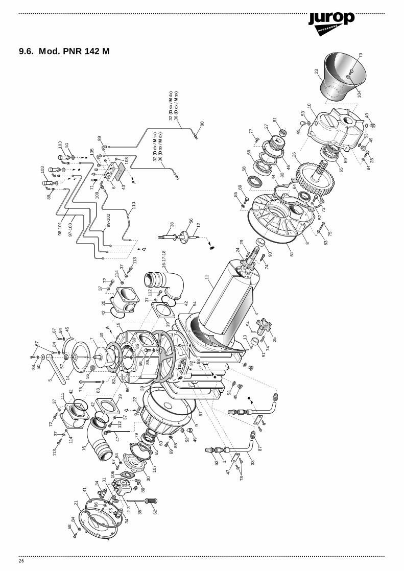
9.6. Mod. PNR 142 M

27
Pos. Code Description Quantity
1 1493300200 Air injection valve PNR 142 22 4024250500 Automatic lubricating pump (cw rotation) 13 4024250000 Automatic lubricating pump (ccw rotation) 14 1601605200 Vane PNR 142 55 1605500100 Handle PNR 142 16 1608100200 Distributor PNR 142 17 1608500700 Conveyor PNR 142 18 1610507900 Flange PNR 142 M 19 1612500900 Oil tank PNR 142 110 1612503000 Gearbox PNR 142 M 111 1621503200 Rotor PNR 142 112 1622002500 Check valve shaft PNR 142 113 1622002600 Shaft M10 114 1623500300 Conveyor cap PNR 142 115 1627501100 Manifold PNR 142 116 1627102400 Conveyor Ø 100 1-217 1627102700 Conveyor Ø 80 118 1627102800 Conveyor Ø 76 119 1610101100 Conveyor flange 220 1627102500 Conveyor with safety valve connection (1)21 1640101000 Oil tank cap PNR 142 122 1642600000 Pipeline protection 423 1642600100 Drive shaft protection 124 1650012800 Front shaft PNR 142 M 125 1650013000 Rear shaft PNR 142 126 1651005200 Gear PNR 142 M 127 1651005300 Pinion PNR 142 M 128 4026100411 Screw M8x30 729 4026501004 Tab 12x8x45 130 1610508500 Automatic lubrication pump flange R-PNR-PNE 131 4026706104 Fitting Ø6-1/8 132 1663016310 Rear lubricating line PNR 142 D rh/M lh 133 1663014000 Air injection valve pipe 1/2" PNR 142 234 4026706101 Fitting Ø4-1/8 135 1663041100 Suction line for aut. lubricating pump PNR 102-122-142 136 1663016610 Rear lubricating line PNR 142 D lh/M rh 137 4026350606 Washer grower M8 8(12)38 1672001200 Check valve stop 139 1680608300 Manifold gasket PNR 142 140 1680702500 Conveyor gasket PNR 142 141 1680702700 Oil tank cap gasket PNR 142 142 4022200310 OR 6362 2(3)43 1680703700 Distributor gasket PNR 142 144 1680707200 Gearbox gasket PNR 142 M 145 1681005300 Plate vac-press PNR 142 146 1681006500 Compensation ring bracket 147 1681006600 Bracket 248 1683600300 Oil stick 149 1684000000 Plug G3/8 650 1685002800 Washer 30x8,5x4 151 1685100000 Alu washer 14x20x1,5 352 1685100100 Alu washer 10x16x1,5 153 1685100200 Alu washer 17x22x1,5 654 1687501900 Housing PNR 142 155 1691000200 Conveyor spring 156 1693500000 Check valve PNR 142 157 4022200030 Seal 41x27x10 158 4022200113 Seal 70x55x15 159 4022200040 Seal 72x40x10 1
Pos. Code Description Quantity
60 4022200111 Seal 72x48x15 161 4022200311 OR 4975 262 4022300001 Nylon filter Ø6 163 4022301004 Silencer-filter 3/4" 264 4023100018 Bearing 6206 165 4023100040 Bearing 6308 266 4023100046 Bearing 6309 167 4026100408 Screw M8x20 868 4026100410 Screw M8x25 669 4026100510 Screw M10x25 1870 4026101404 Screw M8x12 371 4026120303 Screw M6x20 272 4026102807 Screw M8x25 (4)73 4026120505 Screw M10x25 174 1672001600 PNR rotor screw M10 1075 4026120510 Screw M10x50 276 4026120519 Screw M10x110 277 4026155505 Screw M5x16 478 4026155605 Screw M6x16 479 4026300020 Compensation ring Ø90 180 4026300025 Compensation ring Ø100 181 4026306115 Nut M36x3 182 4026322006 Nut M16 183 4026350608 Grower washer M10 484 4026350909 Washer M8 2185 4026350910 Washer M10 1886 4026414611 Pin 3x24 187 4026701301 Fitting G1/2x18 288 4026702000 Fitting Ø4-1/8 489 4026706000 Fitting 90° Ø4-1/8 690 4023130035 Bushing 55x45x22 191 4023130020 Bushing 48x40x22 192 4026120400 Screw M8x12 193 1685100800 Alu washer 14x8x1,5 194 4026414617 Pin 3x40 (*) 195 4026120304 Screw M6x16 296 4026350908 Washer M6 297 1663034200 Rear oil dripper lubricating line PNR 142 D lh/M rh 198 1663034300 Centering oil dripper lubric. line PNR 142 D lh/M rh 199 1663034400 Front oil dripper lubric. line PNR 142 D lh/M rh 1100 1663034500 Rear oil dripper lubric. line PNR 142 D rh/M lh 1101 1663034600 Centering oil dripper lubric. line PNR 142 D rh/M lh 1102 1663034700 Front oil dripper lubric. line PNR 142 D rh/M lh 1103 1401200700 Oil dripper automatic lubrication 3104 4026356002 Flat washer M8 galvanized 3105 4022301000 Oil block filter G 1/8 3106 1680609700 Oil pump gasket 1107 1680609800 Oil pump flange gasket 1108 4026910601 Plug G1/8 2109 4026706003 Fitting 90° G1/8 ø6 1110 1663043700 Oil drain line PNR 142 D dx 1
1663043800 Oil drain line PNR 142 D sx 1111 1627102600 Conveyor (1)112 4026102801 Screw M8x35 8113 4026102810 Screw M8x40 (4)114 4026308005 Nut M8 (4)
(*): on models with cw (right hand) rotation
1892002400 Gaskets kit PNR 142 D 1
Parts list PNR 142 M
Note: between brackets quantity referred to the conveyor with safety valve connection built.

Jurop spaVia Crosera, 5033082 Azzano Decimo/PN · Italy
Telefono ++39 · 434/636811Telefax ++39 · 434/636812
http: //www.jurop.ite-mail: [email protected]
Jurop SpA reserves the right to modify the above described products without notice.
Rev
. 01
- 15
/04/
’01