(Gas/LPG) Scrubber--Sweeper English EN Operator...
94
7400 *330979* www.tennantco.com 330979 Rev. 04 (5-2007) (Gas/LPG) Scrubber--Sweeper English EN Operator Manual
Transcript of (Gas/LPG) Scrubber--Sweeper English EN Operator...

7400
*330979*www.tennantco.com
330979Rev. 04 (5-2007)
(Gas/LPG)
Scrubber--SweeperEnglish EN
Operator Manual

This manual is furnished with each new model. It provides necessary operation and maintenance instructions.
Read this manual completely and understand the machine before operating or servicing it.
This machine will provide excellent service. However, the best results will be obtained at minimum costs if:
S The machine is operated with reasonable care.
S The machine is maintained regularly - per the machine maintenance instructions provided.
S The machine is maintained with manufacturer supplied or equivalent parts.
PROTECT THE ENVIRONMENTPlease dispose of packaging materials,old machine components such asbatteries, hazardous fluids such asantifreeze and oil, in an environmentallysafe way according to local wastedisposal regulations.
Always remember to recycle.
MACHINE DATAPlease fill out at time of installation for future reference.
Model No. --
Serial No. --
Machine Options --
Sales Rep. --
Sales Rep. phone no. --
Customer Number --
Installation Date --
Tennant N.V.Industrielaan 6 5405 ABP.O. Box 6 5400 AA Uden--The [email protected]
Specifications and parts are subject to change without notice.
Copyright E 2004, 2005, 2007 TENNANT, Printed in The Netherlands.

CONTENTS
17400 (GM) 330979 (5--07)
CONTENTS
PageSAFETY PRECAUTIONS 3. . . . . . . . . . . . . . . . .OPERATION 7. . . . . . . . . . . . . . . . . . . . . . . . . . . .
OPERATOR RESPONSIBILITY 7. . . . . . . . .MACHINE COMPONENTS 8. . . . . . . . . . . . .SYMBOL DEFINITIONS 9. . . . . . . . . . . . . . . .CONTROLS AND INSTRUMENTS 10. . . . . .OPERATION OF CONTROLS 11. . . . . . . . . .
DIRECTIONAL PEDAL 11. . . . . . . . . . . . . .BRAKE PEDAL 12. . . . . . . . . . . . . . . . . . . .PARKING BRAKE PEDAL 12. . . . . . . . . . .CHARGING SYSTEM LIGHT 12. . . . . . . .ENGINE OIL PRESSURE LIGHT 13. . . . .HIGH ENGINE TEMPERATURE
LIGHT 13. . . . . . . . . . . . . . . . . . . . . . . . . .MAINTENANCE MODE LIGHT 13. . . . . . .RECOVERY TANK FULL LIGHT 13. . . . .HYDRAULIC FILTER LIGHT (OPTION) 14FUEL LEVEL LIGHT 14. . . . . . . . . . . . . . . .OK LIGHT 14. . . . . . . . . . . . . . . . . . . . . . . . .HOURMETER 14. . . . . . . . . . . . . . . . . . . . .FUEL LEVEL GAUGE 15. . . . . . . . . . . . . . .SQUEEGEE SWITCH 15. . . . . . . . . . . . . . .ES SWITCH 16. . . . . . . . . . . . . . . . . . . . . . .SIDE BRUSH SWITCH 16. . . . . . . . . . . . . .DETERGENT FLOW SWITCH 16. . . . . . .SCRUB SWITCH 17. . . . . . . . . . . . . . . . . . .ENGINE SPEED SWITCH 18. . . . . . . . . . .STEERING WHEEL 18. . . . . . . . . . . . . . . .COVER RELEASE KNOB 18. . . . . . . . . . .HORN BUTTON 19. . . . . . . . . . . . . . . . . . . .IGNITION SWITCH 19. . . . . . . . . . . . . . . . .STEERING COLUMN TILT HANDLE 19. .CHECK ENGINE LIGHT 20. . . . . . . . . . . . .CIRCUIT BREAKERS 20. . . . . . . . . . . . . . .FUSES 21. . . . . . . . . . . . . . . . . . . . . . . . . . . .SOLUTION FLOW SWITCH
(WITHOUT FaST) 22. . . . . . . . . . . . . . .SOLUTION FLOW SWITCH (FaST) 22. .FaST SWITCH 22. . . . . . . . . . . . . . . . . . . . .OPERATOR SEAT 23. . . . . . . . . . . . . . . . . .SOLUTION TANK DRAIN HOSE 23. . . . .RECOVERY TANK DRAIN HOSE 23. . . .LATCHES 24. . . . . . . . . . . . . . . . . . . . . . . . .
HOW THE MACHINE WORKS 24. . . . . . . . . .FaST SCRUBBING SYSTEM 25. . . . . . . . . . .PRE-OPERATION CHECKLIST 26. . . . . . . . .INSTALLING FaST PAK AGENT 27. . . . . . . .CHANGING AN LPG FUEL TANK 29. . . . . . .STARTING THE MACHINE 31. . . . . . . . . . . . .SCRUBBING AND BRUSH INFORMATION 33FILLING THE TANKS 34. . . . . . . . . . . . . . . . . .SCRUBBING 36. . . . . . . . . . . . . . . . . . . . . . . . .DOUBLE SCRUBBING 39. . . . . . . . . . . . . . . . .STOP SCRUBBING 39. . . . . . . . . . . . . . . . . . .DRAINING AND CLEANING THE TANKS 40STOP THE MACHINE 43. . . . . . . . . . . . . . . . .POST-OPERATION CHECKLIST 45. . . . . . . .OPERATION ON INCLINES 45. . . . . . . . . . . .
PageOPTIONS 46. . . . . . . . . . . . . . . . . . . . . . . . . . . .
VACUUM WAND 46. . . . . . . . . . . . . . . . . . .POWER WAND 49. . . . . . . . . . . . . . . . . . . .
MACHINE TROUBLESHOOTING 55. . . . . . .MAINTENANCE 58. . . . . . . . . . . . . . . . . . . . . . . . .
MAINTENANCE CHART 58. . . . . . . . . . . . . . .LUBRICATION 60. . . . . . . . . . . . . . . . . . . . . . . .
ENGINE 60. . . . . . . . . . . . . . . . . . . . . . . . . . .REAR WHEEL BEARINGS 60. . . . . . . . . .FRONT WHEEL SUPPORT BEARING 61SCRUB BRUSH IDLER 61. . . . . . . . . . . . .
HYDRAULICS 62. . . . . . . . . . . . . . . . . . . . . . . .HYDRAULIC FLUID RESERVOIR 62. . . .HYDRAULIC FLUID 62. . . . . . . . . . . . . . . .HYDRAULIC HOSES 63. . . . . . . . . . . . . . .PROPELLING MOTOR 63. . . . . . . . . . . . . .
ENGINE 64. . . . . . . . . . . . . . . . . . . . . . . . . . . . .COOLING SYSTEM 64. . . . . . . . . . . . . . . .AIR FILTER INDICATOR 66. . . . . . . . . . . .AIR FILTER 67. . . . . . . . . . . . . . . . . . . . . . . .SPARK PLUGS 67. . . . . . . . . . . . . . . . . . . .CRANKCASE VENTILATION SYSTEM 67TIMING BELT 67. . . . . . . . . . . . . . . . . . . . . .FUEL FILTER (GASOLINE) 67. . . . . . . . . .FUEL FILTER (LPG) 68. . . . . . . . . . . . . . . .ELECTRONIC PRESSURE REGULATOR
(LPG) (For machines serial number7400 xxxx and above) 68. . . . . . . . .
ELECTRONIC FUEL INJECTION 68. . . . .BATTERY 69. . . . . . . . . . . . . . . . . . . . . . . . .PROPELLING MOTOR 69. . . . . . . . . . . . . .
BELTS AND CHAINS 69. . . . . . . . . . . . . . . . . .ENGINE BELT 69. . . . . . . . . . . . . . . . . . . . .STATIC DRAG CHAIN 69. . . . . . . . . . . . . .
SCRUB BRUSHES 70. . . . . . . . . . . . . . . . . . . .REPLACING OR ROTATING THE
SCRUB BRUSHES 71. . . . . . . . . . . . . .CHECKING AND ADJUSTING
SCRUB BRUSH PATTERN 72. . . . . . .SIDE BRUSH 74. . . . . . . . . . . . . . . . . . . . . .
REPLACING THE SIDE SCRUBBRUSH 74. . . . . . . . . . . . . . . . . . . . . .
SOLUTION SYSTEM 75. . . . . . . . . . . . . . . . . .RECOVERY TANK 75. . . . . . . . . . . . . . . . .SOLUTION TANK 75. . . . . . . . . . . . . . . . . .DEBRIS TRAY 75. . . . . . . . . . . . . . . . . . . . .FaST SYSTEM 76. . . . . . . . . . . . . . . . . . . . .
FaST SUPPLY HOSE CONNECTOR 76FaST SYSTEM FILTER SCREEN 76. .FaST SYSTEM AIR PUMP FILTER 76FaST SPRAY TUBE 77. . . . . . . . . . . . .
SQUEEGEES 77. . . . . . . . . . . . . . . . . . . . . . . . .ADJUSTING REAR SQUEEGEE
BLADE DEFLECTION 77. . . . . . . . . . . .LEVELING THE REAR SQUEEGEE 79. .SQUEEGEE BLADES 80. . . . . . . . . . . . . . .
REAR SQUEEGEE 80. . . . . . . . . . . . . .REPLACING OR ROTATING
REAR SQUEEGEE BLADES 80

CONTENTS
7400 (GM) 330979 (5--07)2
PageSIDE SQUEEGEES 81. . . . . . . . . . . . . .
REPLACING SIDE SQUEEGEEBLADES 81. . . . . . . . . . . . . . . . . .
SIDE BRUSH SQUEEGEE 82. . . . . . .REPLACING THE SQUEEGEE
BLADE 82. . . . . . . . . . . . . . . . . . .SKIRTS AND SEALS 83. . . . . . . . . . . . . . . . . .
SCRUB HEAD SKIRTS 83. . . . . . . . . . . . .SIDE BRUSH SKIRT 83. . . . . . . . . . . . . . . .COVER SEALS 83. . . . . . . . . . . . . . . . . . . .
BRAKES AND TIRES 84. . . . . . . . . . . . . . . . . .SERVICE BRAKES 84. . . . . . . . . . . . . . . . .PARKING BRAKE 84. . . . . . . . . . . . . . . . . .TIRES 84. . . . . . . . . . . . . . . . . . . . . . . . . . . .FRONT WHEEL 84. . . . . . . . . . . . . . . . . . . .
PUSHING, TOWING, ANDTRANSPORTING THE MACHINE 85. . . .PUSHING OR TOWING THE MACHINE 85TRANSPORTING THE MACHINE 86. . . .
MACHINE JACKING 88. . . . . . . . . . . . . . . . . . .STORING MACHINE 88. . . . . . . . . . . . . . . . . .
SPECIFICATIONS 89. . . . . . . . . . . . . . . . . . . . . . .GENERAL MACHINE PERFORMANCE 89. .FaST SYSTEM 89. . . . . . . . . . . . . . . . . . . . . . .POWER TYPE 90. . . . . . . . . . . . . . . . . . . . . . . .STEERING 90. . . . . . . . . . . . . . . . . . . . . . . . . . .HYDRAULIC SYSTEM 90. . . . . . . . . . . . . . . . .BRAKING SYSTEM 90. . . . . . . . . . . . . . . . . . .TIRES 90. . . . . . . . . . . . . . . . . . . . . . . . . . . . . . .MACHINE DIMENSIONS 91. . . . . . . . . . . . . . .

SAFETY PRECAUTIONS
37400 (GM) 330979 (12--05)
SAFETY PRECAUTIONS
The following precautions are used throughoutthis manual as indicated in their description:
WARNING: To warn of hazards or unsafepractices that could result in severepersonal injury or death.
CAUTION: To warn of unsafe practicesthat could result in minor or moderatepersonal injury.
FOR SAFETY: To identify actions thatmust be followed for safe operation ofequipment.
The machine is suited to sweep disposable debris.Do not use the machine other than described inthis Operator Manual. The machine is notdesigned for use on public roads.
The following information signals potentiallydangerous conditions to the operator orequipment:
WARNING: Engine emits toxic gases.Severe respiratory damage orasphyxiation can result. Provideadequate ventilation. Consult with yourregulatory authorities for exposurelimits. Keep engine properly tuned.
WARNING: Flammable materials cancause an explosion or fire. Do not useflammable materials in tank(s).
WARNING: Flammable materials orreactive metals can cause an explosionor fire. Do not pickup.
WARNING: Moving belt and fan. Keepaway.
WARNING: Strong Vacuum. Keep AwayFrom Fan Inlet When Fan Is Running.
WARNING: Hot bumper. Keep away.
CAUTION: LPG engine will run for a fewseconds after key is turned off. Applyparking brake before leaving machine.
FOR SAFETY:
1. Do not operate machine:-- Unless trained and authorized.-- Unless operator manual is read andunderstood.
-- If it is not in proper operatingcondition.
-- In flammable or explosive areas unlessdesigned for use in those areas.
-- In areas with possible falling objectsunless equipped with overhead guard.
2. Before starting machine:-- Check for fuel, oil, and liquid leaks.-- Keep sparks and open flame awayfrom refueling area.
-- Make sure all safety devices are inplace and operate properly.
-- Check brakes and steering for properoperation.
3. When starting machine:-- Keep foot on brake and directionalpedal in neutral.
4. When using machine:-- Use brakes to stop machine.-- Go slow on inclines and slipperysurfaces.
-- Use care when reversing machine.-- Do not carry passengers on machine.-- Always follow safety and traffic rules.-- Report machine damage or faultyoperation immediately.
-- Follow mixing and handlinginstructions on chemical containers.
5. Before leaving or servicing machine:-- Stop on level surface.-- Set parking brake.-- Turn off machine and remove key.

SAFETY PRECAUTIONS
7400 (GM) 330979 (3--04)4
6. When servicing machine:-- Avoid moving parts. Do not wear loosejackets, shirts, or sleeves.
-- Block machine tires before jackingmachine up.
-- Jack machine up at designatedlocations only. Block machine up withjack stands.
-- Use hoist or jack that will support theweight of the machine.
-- Wear eye and ear protection whenusing pressurized air or water.
-- Disconnect battery connections beforeworking on machine.
-- Avoid contact with battery acid.-- Avoid contact with hot engine coolant.-- Allow engine to cool.-- Keep flames and sparks away fromfuel system service area. Keep areawell ventilated.
-- Use cardboard to locate leakinghydraulic fluid under pressure.
-- Use Tennant supplied or approvedreplacement parts.
7. When loading/unloading machineonto/off truck or trailer:-- Turn off machine.-- Use truck or trailer that will supportthe weight the machine.
-- Use winch. Do not drive the machineonto/off the truck or trailer unless theload height is 380 mm (15 in) or lessfrom the ground.
-- Set parking brake after machine isloaded.
-- Block machine tires.-- Tie machine down to truck or trailer.

SAFETY PRECAUTIONS
57400 (GM) 330979 (12--05)
The following safety labels are mounted on themachine in the locations indicated. If these or anylabels become damaged or illegible, install a newlabel in its place.
EMISSIONS LABEL -- LOCATED ON THE SIDEOF THE OPERATOR COMPARTMENT.
10783
FOR SAFETY LABEL -- LOCATED ON THESIDE OF THE OPERATOR COMPARTMENT.
FLAMMABLE SPILLS LABEL -- LOCATED ONTHE SIDE OF THE OPERATOR COMPARTMENT.
LPG ENGINE WILL RUN LABEL -- LOCATEDNEXT TO THE IGNITION SWITCH ON THEINSTRUMENT PANEL.

SAFETY PRECAUTIONS
7400 (GM) 330979 (11--04)6
FAN AND BELT LABEL -- LOCATED ON THEENGINE COMPARTMENT LINTEL.
10783
STRONG VACUUM LABEL -- LOCATED ONTHE VACUUM FAN HOUSING.
FLAMMABLE MATERIALS LABEL -- LOCATEDNEXT TO THE SOLUTION TANK COVERS ANDON THE DETERGENT TANK.
HOT SURFACE LABEL --LOCATED ON THE SIDEOF THE BUMPER.

OPERATION
77400 (GM) 330979 (3--04)
OPERATION
OPERATOR RESPONSIBILITY
- The operator’s responsibility is to take careof the daily maintenance and checkups ofthe machine, to keep it in good workingcondition. The operator must inform theservice mechanic or supervisor when therequired maintenance intervals occur asstated in the MAINTENANCE section of thismanual.
- Read this manual carefully before operatingthis machine. View the operation videosupplied with the machine.
FOR SAFETY: Do not operate machine,unless operation manual is read andunderstood.
- Check the machine for shipping damage.Check to make sure the machine iscomplete per shipping instructions.
- Keep your machine regularly maintained byfollowing the maintenance information in thismanual. We recommend taking advantage ofa regularly scheduled service contract fromyour Tennant representative.
- Order parts and supplies directly from yourauthorized Tennant representative. Use theparts manual provided when ordering parts.
- After the first 50 hours of operation, followthe recommended procedures stated in theMAINTENANCE CHART.
07324

OPERATION
7400 (GM) 330979 (5--07)8
MACHINE COMPONENTS
AB
C
D
E
F
GH
I
J
K
L
F
G
H
M
N
10783
A. Instrument panelB. Steering wheelC. Operator seatD. Engine coverE. Machine front coverF. Solution tank coversG. Solution tanksH. Recovery tank coversI. Recovery TankJ. Rear squeegeeK. Side SqueegeeL. Scrub brush access doorM. FaST solution systemN. Fuel tank

OPERATION
97400 (GM) 330979 (11--04)
SYMBOL DEFINITIONS
These symbols identify controls, displays, andfeatures on the machine:
Charging system Engine
Engine oil pressure Steering tilt
High engine temperature Horn
Maintenance mode Circuit breaker 1
Recovery tank full Circuit breaker 2
Hydraulic filter Circuit breaker 3
Fuel Circuit breaker 4
Diagnostics Circuit breaker 5
Hourmeter Circuit breaker 7
ES Circuit breaker 8
Side brush down and on Cover release
Rear squeegee down and vacuum on Hydraulic fluid only
Detergent flow Gasoline fuel only
Solution flow Jack-point
Scrub brushes down and on Check Engine

OPERATION
7400 (GM) 330979 (3--05)10
CONTROLS AND INSTRUMENTS
B
C
D
E
F
G
H
JK
L M N
P
Q
R
S
TU
V
X
A
WY
AA
Z
BBCC
I
O
10654
A. Directional pedalB. Brake pedalC. Parking brake pedalD. Charging system lightE. Engine oil pressure lightF. High engine temperature lightG. Maintenance mode lightH. Recovery tank full lightI. Hydraulic filter light (option)J. Fuel level low lightK. OK lightL. Fuel level gaugeM. HourmeterN. ES switchO. Side brush switchP. Squeegee switchQ. Detergent flow switchR. Scrub switchS. Engine speed switchT. Steering wheelU. Horn buttonV. Ignition switchW. Steering column tilt leverX. Circuit breakersY. Solution flow switchZ. Check engine lightAA.Cover release knobBB.FaST switchCC.FaST solution flow switch

OPERATION
117400 (GM) 330979 (3--04)
OPERATION OF CONTROLS
DIRECTIONAL PEDAL
The directional pedal controls direction of traveland the propelling speed of the machine. Youchange the speed of the machine with thepressure of your foot; the harder you press thefaster the machine travels.
Forward: Press the top of the directional pedalwith the toe of your foot.
Reverse: Press the bottom of the directionalpedal with the heel of your foot.
Neutral: Take your foot off the directional pedaland it will return to the neutral position.

OPERATION
7400 (GM) 330979 (3--04)12
BRAKE PEDAL
The brake pedal stops the machine.
Stop: Take your foot off the directional pedal andlet it return to the neutral position. Step on thebrake pedal.
PARKING BRAKE PEDAL
The parking brake pedal sets and releases therear wheel brakes.
Set: Press on the brake pedal as far as possible,then press on the parking brake pedal with the toeportion of your foot to lock the parking brake pedalin place.
FOR SAFETY: Before leaving orservicing machine; stop on levelsurface, set parking brake, turn offmachine and remove key.
Release: Press on the brake pedal to unlock theparking brake pedal.
CHARGING SYSTEM LIGHT
The charging system light comes on when thealternator is not operating within normal range;13.5 to 14.5 Volts. Stop operating the machine.Locate the problem and have it corrected.
10642
OPERATION
137400 (GM) 330979 (5--07)
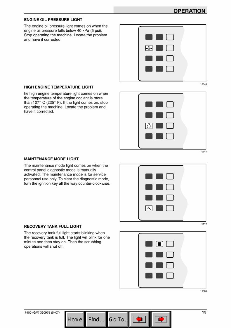
ENGINE OIL PRESSURE LIGHT
The engine oil pressure light comes on when theengine oil pressure falls below 40 kPa (5 psi).Stop operating the machine. Locate the problemand have it corrected.
HIGH ENGINE TEMPERATURE LIGHT
he high engine temperature light comes on whenthe temperature of the engine coolant is morethan 107_ C (225_ F). If the light comes on, stopoperating the machine. Locate the problem andhave it corrected.
MAINTENANCE MODE LIGHT
The maintenance mode light comes on when thecontrol panel diagnostic mode is manuallyactivated. The maintenance mode is for servicepersonnel use only. To clear the diagnostic mode,turn the ignition key all the way counter-clockwise.
RECOVERY TANK FULL LIGHT
The recovery tank full light starts blinking whenthe recovery tank is full. The light will blink for oneminute and then stay on. Then the scrubbingoperations will shut off.
10643
10644
10645
10886

OPERATION
7400 (GM) 330979 (3--04)14
HYDRAULIC FILTER LIGHT (OPTION)
The hydraulic filter light comes on when thehydraulic filter is clogged. Have the hydraulic filterand hydraulic fluid changed as soon as possible.
FUEL LEVEL LIGHT
The fuel level light comes on when the gasoline orLPG fuel tank is almost empty. The LPG fuel tankhas five minutes of fuel remaining when the levellight comes on.
OK LIGHT
The OK light comes on after the control panel hasrun through and passed a self-check every timethe machine is started. The OK light will go outwhen the scrub or squeegee switch is activated,or the engine speed is changed to (Fast).
HOURMETER
The hourmeter records the number of hours themachine has been operated. The hourmeterdisplays the number of hours in tenths of an hour.Use this information to determine machinemaintenance intervals.
10887
10888
10889
07765

OPERATION
157400 (GM) 330979 (3--04)
FUEL LEVEL GAUGE
The fuel level gauge indicates how much fuel is inthe fuel tank with a segmented LED light.
Gasoline powered machine: When the tank is full,all ten of the LED segments are lit. As the fueltank empties, the LED segments shut off. The fueltank is empty when all ten of the LED segmentshave shut off. The fuel level light comes on whenthe last three LED segments are lit.
LPG powered machines: The fuel level gauge isnot operational on LPG machines. However, thefuel level light comes on when there is fiveminutes of fuel remaining in the tank.
NOTE: Do not use leaded fuels. The use ofleaded fuels will cause permanent damage to thesystem’s oxygen sensor and the catalyticconverter.
SQUEEGEE SWITCH
The squeegee switch controls the position of therear squeegee, and starts and stops the vacuumfan. The rear squeegee can be operatedseparately, from the scrub brushes, for waterpick-up.
Lower and start: Press the squeegee switch. Theindicator light above the switch will come on.
Raise and stop: Press the squeegee switch. Theindicator light above the switch goes off. There willbe a slight delay before the vacuum fan shuts off.
NOTE: The rear squeegee lowers and thevacuum fan starts automatically when thescrubbing operations start.
NOTE: The rear squeegee will raise and thevacuum fan will stop when the machine travels inreverse.
NOTE: The rear squeegee will raise and thevacuum fan will shut off after a short delay whenthe scrubbing operations are shut off.
07764
10892

OPERATION
7400 (GM) 330979 (11--04)16
ES SWITCH
The ES switch turns on and off the extendedscrub system. When the machine is started, theES switch will default to the last setting used.
On: Press the ES switch. The indicator lightabove the switch will come on.
Off: Press the ES switch. The indicator lightabove the switch goes off.
SIDE BRUSH SWITCH
The side brush switch controls the position androtation of the side brush, and the solution flow tothe side brush. When the machine is started, theside brush switch will default to the last settingused.
Down and on: Press the side brush switch. Theindicator above the switch comes on.
Up and off: Press the side brush switch. Theindicator above the switch goes off.
NOTE: The side brush will lower and start whenthe scrubbing operations start. The main scrubbrushes have to be on for the side brush tooperate.
DETERGENT FLOW SWITCH
The detergent flow switch starts and stops thedetergent pump for the optional ES system. Whenthe machine is started, the detergent flow switchwill default to the last setting used.
Start at one-half flow: Press the detergent flowswitch. The left indicator light above the switch willcome on.
Increase to full flow: Press and hold the detergentflow switch until both indicator lights above theswitch come on.
Stop: Press the detergent flow switch. Bothindicator lights are off.
10890
10891
10893

OPERATION
177400 (GM) 330979 (3--05)
SCRUB SWITCH
The scrub switch controls the scrubbingoperations. The scrub switch also sets the scrubbrush pressure.
The scrubbing operations include the following.The scrub head lowers and the brushes turn on.The rear squeegee will lower and the vacuum fanwill start. The solution system will start, if thesolution flow switch is on. The FaST system oroptional ES system and detergent pump will start,if the switches are on. The optional side brush willlower and turn on, if the side brush switch is on.The engine speed will change to (Fast).
NOTE: The brush pressure setting, the FaSTsystem, the detergent flow rate, the side brush,and the ES system will default to the last settingused when the scrubbing operations are startedagain.
Start: Press the scrub switch. The indicator lightabove the switch will come on.
Stop: Press the scrub switch. The indicator lightabove the switch goes off.
Scrub brush pressure: Press and hold the scrubswitch. The brush pressure will scroll through thethree settings. The pressure setting selected whenthe switch is released, will be the new defaultbrush pressure setting.
The brush pressure has three positions. Undernormal conditions, the brush pressure should beset in the minimum setting. Under heavy grimeconditions, the brush pressure should be set in themaximum setting. Travel speed and floorconditions will affect the scrubbing performance.
NOTE: The brush pressure setting, the sidebrush, and the detergent flow rate will default tothe last setting used, when the scrubbingoperations are started again.
NOTE: The scrub head and squeegee will raisewhen the machine travels in reverse.
10894

OPERATION
7400 (GM) 330979 (3--04)18
ENGINE SPEED SWITCH
The engine speed switch controls the enginegoverned speed. The two indicator lights abovethe switch show the engine speed; idle or fast.
Idle: The engine will automatically start in idlespeed. To return the engine to idle from the (Fast)engine speed, press the engine speed switch untilthe left indicator light comes on. The scrubbingoperations will turn off automatically.
Fast: Press the engine speed switch and the rightindicator light comes on. This speed is fortransporting and scrubbing.
NOTE: The engine will automatically operate inthe (Fast) speed when the scrubbing operationsare started.
STEERING WHEEL
The steering wheel controls the machine’sdirection. The machine is very responsive to thesteering wheel movements.
Left: Turn the steering wheel to the left.
Right: Turn the steering wheel to the right.
COVER RELEASE KNOB
The cover release knob releases the machinefront cover latch.
To release: Pull out and hold the cover releaseknob, then pull open the machine cover.
10895

OPERATION
197400 (GM) 330979 (12--05)
HORN BUTTON
The horn button operates the horn.
Sound: Press the button.
IGNITION SWITCH
The ignition switch starts and stops the enginewith a key. The operating lights will automaticallyturn on when the machine is started.
FOR SAFETY: When starting machine,keep foot on brake and directional pedalin neutral.
Start: Turn the key all the way clockwise. Releasethe key as soon as the engine starts.
Stop: Turn the key counter-clockwise.
CAUTION: LPG engine will run for a fewseconds after key is turned off. Applyparking brake before leaving machine.
NOTE: To protect the engine’s emissioncomponents on LPG powered machines, theengine will continue to operate for a few secondsafter the ignition switch is turned off.
STEERING COLUMN TILT HANDLE
The steering wheel tilt handle adjusts the angle ofthe steering wheel.
Adjust: Pull out the tilt handle, move the wheel upor down, and release the tilt handle.

OPERATION
7400 (GM) 330979 (3--05)20
CHECK ENGINE LIGHT
The check engine light comes on if the enginecontrol system detects a fault during machineoperation.
If the check engine light comes on while operatingthe machine, contact a TENNANT servicerepresentative.
CIRCUIT BREAKERS
The circuit breakers are resetable electrical circuitprotection devices. Their design stops the flow ofcurrent in the event of a circuit overload. Once acircuit breaker is tripped, it must be resetmanually. Press the reset button after the breakerhas cooled down.
If the overload that caused the circuit breaker totrip is still there, the circuit breaker will continue tostop current flow until the problem is corrected.
The circuit breakers are located in the operatorcompartment.
The chart lists the circuit breakers and theelectrical components they protect.
CircuitBreaker Rating Circuit Protected
CB-1 15 A Ignition
CB-2 15 A ES (option)
CB-3 15 A Operating lights
CB-4 15 A Back-up alarm (option)
CB-5 15 A Horn
CB-6 5 A Instrument panel (7400 0400--xxxx)
CB-6 15 A Instrument panel (7400 xxxx-- )
CB-7 15 A Scrubbing
CB-8 15 A Side brush (option)

OPERATION
217400 (GM) 330979 (11--04)
FUSES
The fuses are one-time protection devicesdesigned to stop the flow of current in the event ofa circuit overload.
NOTE: Always replace the fuse with a fuse of thesame amperage.
The main harness fuse is located near the relaysunder the front hood. Access the fuse by openingthe front hood.
Main Harness Fuse
Fuse Rating Circuit Protected
FU-1 15 A Circuit board
The engine harness fuses are located near theengine under the engine cover. Access the fusesby opening the engine cover.
Engine Harness Fuses
Fuse Rating Circuit Protected
FU-1 5 A Key switch
FU-2 20 A Main power
FU-3 15 A Auxilary power
FU-4 15 A Fuel pump
FU-5 50 A Alternator

OPERATION
7400 (GM) 330979 (3--05)22
SOLUTION FLOW SWITCH (WITHOUT FaST)
The solution flow switch controls the flow ofsolution to the floor. The solution flow switch isonly on machines without the FaST system.
Start (1): Place the solution flow switch in themiddle position. Use this flow rate for smoothfloors and light dirt.
Increase (2): Press the right of the solution flowswitch. Use this flow rate for rough floors andheavy or compacted dirt.
Stop (0): Press the left of the solution flow switch.
NOTE: The solution flow starts, if the solutionflow switch is on, when the scrubbing operationsstart.
SOLUTION FLOW SWITCH (FaST)
The FaST solution flow switch enables the FaST(Foam Scrubbing Technology) system. When theFaST system is enabled, it is turned on and offwith the FaST switch. Disable the FaST systembefore using the machine for conventionalscrubbing.
For machines with the FaST system, the FaSTsolution flow switch controls the flow of solution tothe floor.
Start (1): Place the FaST solution flow switch inthe middle position. Use this flow rate for smoothfloors and light dirt.
Increase (2): Press the top of the FaST solutionflow switch. Use this flow rate for rough floors andheavy or compacted dirt.
Stop (0): Press the bottom of the FaST solutionflow switch.
FaST SWITCH
The FaST switch enables the FaST (FoamScrubbing Technology) system. When the FaSTsystem is enabled, it is turned on and off with theFaST switch. Disable the FaST system beforeusing the machine for conventional scrubbing.
Disable FaST for conventional scrubbing: Pressthe bottom of switch to the FaST system offposition.
Enable the FaST system: Press the top of switchto the FaST system on position.
NOTE: The FaST system will not start until thedirectional pedal is pressed.

OPERATION
237400 (GM) 330979 (3--04)
OPERATOR SEAT
The operator seat is a fixed back style with aforward-backward position adjustment.
Adjust: Pull the lever, slide the seat backward orforward to the desired position and release thelever.
Lift: Pull up on the seat mounting plate until theseat mount locks up.
Lower: Pull on the release lever and lower theseat mounting plate.
SOLUTION TANK DRAIN HOSE
The solution tank drain hose is used to drain thesolution tank. Drain the solution tank by removingthe drain hose cap from the tank access cap. Pullout the solution tank hose and remove the drainhose end cap.
RECOVERY TANK DRAIN HOSE
The recovery tank drain hose is used to drain therecovery tank. Drain the recovery tank byremoving the drain hose cap from the tank accesscap. Pull out the recovery tank hose and removethe drain hose end cap.

OPERATION
7400 (GM) 330979 (11--04)24
LATCHES
The side doors, engine cover, debris tray, backgrille, and solution tank covers are secured withlatches.
Open the brush side doors: Push down on thedoor latch.
Open the engine side door: Pull out on the doorlatch.
Open the engine cover: Open the engine sidedoor and pull on the latch release.
Release the debris tray: Pull down on the latchhandle.
Open the back grille: Pull up on the latches.
Open the solution tank covers: Pull up on thecover latch.
HOW THE MACHINE WORKS
The steering wheel controls the direction ofmachine travel. The directional pedal controls thespeed and forward/reverse direction. The brakepedal slows and stops the machine.
Water and detergent, from the solution tank, flowto the floor through a solution valve to the scrubbrushes. The brushes scrub the floor. As themachine travels forward the squeegee wipes thedirty solution off the floor, which is then picked upand drawn into the recovery tank.
When using the ES mode, the solution in therecovery tank is filtered and returned to thesolution tank to be reused.
When scrubbing is finished, drain and clean therecovery tank. If using the ES system, drain andclean the solution tank, clean the solution outletfilter, and clean the ES filter.

OPERATION
257400 (GM) 330979 (5--07)
FaST SCRUBBING SYSTEM
Unlike conventional scrubbing, the FaST (FoamScrubbing Technology) system operates byinjecting the FaST PAK concentrate agent into thesystem with a small amount of water andcompressed air. This mixture creates a largevolume of expanded wet foam.
The expanded foam mixture is then dispersedonto the floor while the machine is scrubbing.When the squeegee picks up the mixture, thepatented foaming agent has collapsed and isrecovered into the recovery tank.
The FaST system can be used with all doublescrubbing and heavy duty scrubbing applications.
Using the FaST system can increaseproductivity by 30% by reducing your dump/fillcycle. It will also reduce chemical usage andstorage space. One FaST PAK of concentratedagent can scrub up to 1 million sq. ft.
NOTE: Do not enable the FaST system withconventional cleaning detergents in the solutiontank. Drain, rinse and refill the solution tank withclear cool water only before operating the FaSTsystem. Conventional cleaning detergents/restorers may cause failure to the FaST solutionsystem.
NOTE: Storage or transporting machinesequipped with FaST in freezing temperaturesrequires special procedures. Check with aTENNANT representative for advice.
The safe scrubbing alternative

OPERATION
7400 (GM) 330979 (3--05)26
PRE-OPERATION CHECKLIST
- Check under the machine for leaks (fuel, oil,coolant, scrubbing solution).
- Check the engine air filter indicator.
- Check the engine oil level.
- Check the fuel level.
- Check the brakes and steering for properoperation.
- Check the rear squeegee for wear andproper deflection. Check the side squeegeesfor wear.
- Check for wire, string, or twine wrappedaround the scrub brushes.
- Check the vacuum hoses for debris orobstructions.
- Check that the debris tray is empty andclean.
- ES machines. Check that the ES filter andsolution outlet filter is clean.
- Check for loose fittings, or wires.
- Check the condition of the v--belt.
- Check the hydraulic oil level.
- Check the cooling system level.
- ES machines. Check detergent level in thedetergent tank, fill as required.
- FAST Scrubbing: Check the FaST PAKconcentrate agent level, replace carton asneeded. See the INSTALLING THE FaSTPAK AGENT section of the manual.
- FAST Scrubbing: Check that all conventionalcleaning agents/restorers are drained andrinsed from the solution tank.
- FAST Scrubbing: Check that the solutiontank is filled with clear cool water only.

OPERATION
277400 (GM) 330979 (3--05)
INSTALLING FaST PAK AGENT
NOTE: Machine must be equipped with FaSTbefore the FaST PAK agent can be installed.
1. Remove the perforated knock--outs from theFaST PAK Floor Cleaning Concentratecarton. Do not remove the bag from thecarton. Pull out the bag’s hose connector onthe bottom of the bag and remove the hosecap from the connector.
NOTE: The FaST PAK Floor CleaningConcentrate is specifically designed for usewith the FaST system scrubbing application.NEVER use a substitute, machine damage willresult.
FOR SAFETY: When using machine,always follow the handling instructionson chemical container.
2. Empty the solution tank. See the DRAININGAND CLEANING THE TANKS section of themanual.
NOTE: When scrubbing with the FaST systemoption, use clean water only. Do not add cleaningagents in the solution tank. Conventional cleaningagents/restorers may cause failure to the FaSTsolution system..
3. Raise the seat mounting plate to access theFaST PAK carton.

OPERATION
7400 (GM) 330979 (12--05)28
4. Connect the supply hose to the FaST PAKbag.
NOTE: If any dried concentrate is visible on thesupply hose connector or the on the FaST PAKconnector, soak and clean with warm water.
5. Place the FaST PAK carton in the cartonholder under the seat mounting plate on themachine.
NOTE: Make sure the supply hose is not pinched.
6. Make sure to connect the supply hose ontothe hose storing plug when the supply hoseis not connected to the FaST PAK. This willprevent the FaST solution system fromdrying out and clogging up the hose.
7. When replacing an empty FaST PAK carton,allow the new FaST PAK detergent to gravityfeed into the system for several minutesprior to operating the FaST system. If thedetergent does not flow out of the FaSTPAK, simply squeeze and release the hoseseveral times. If the previous FaST PAK wasrun dry, it may take up to 5--10 minutes ofoperation to remove any air pockets in thesystem before you achieve maximumfoaming.

OPERATION
297400 (GM) 330979 (3--04)
CHANGING AN LPG FUEL TANK
1. Park the machine in a designated safe area.
2. Open the machine front cover.
3. Close the tank service valve on the LPGtank.
4. Operate the engine until it stops from lack offuel, turn the ignition switch off, then set themachine parking brake.
FOR SAFETY: When servicing machine,Keep flames and sparks away from fuelsystem service area. Keep area wellventilated.
5. Put on gloves and remove thequick-disconnect tank coupling.
6. Unlatch and remove the empty LPG fueltank from the machine and store the tank ina designated, safe area.
NOTE: Make sure the LPG fuel tank matches thefuel system (liquid tank with liquid system).
7. Carefully put the filled LPG tank in themachine so that the tank centering pinenters the aligning hole in the tank collar.
8. Fasten the tank hold-down clamp to lock thetank in position.
07810
07811
07812

OPERATION
7400 (GM) 330979 (3--04)30
9. Connect the LPG fuel line to the tank servicecoupling. Make sure the service coupling isclean and free of damage. Also make sure itmatches the machine service coupling.
10. Open the tank service valve slowly andcheck for leaks. Close the service valveimmediately if an LPG leak is found, and tellthe appropriate personnel.
07813
07814

OPERATION
317400 (GM) 330979 (3--04)
STARTING THE MACHINE
1. LPG powered machines: Open the liquidservice valve slowly.
NOTE: Opening the service valve too quickly maycause the service check valve to stop the flow ofLPG fuel. If the check valve stops the fuel flow,close the service valve, wait a few seconds andopen the valve slowly again.
2. You must be in the operator’s seat with thedirectional pedal in neutral, and your foot onthe brake pedal or with the parking brakeset.
FOR SAFETY: When starting machine,keep foot on brake and directional pedalin neutral.
3. Turn the ignition switch key clockwise untilthe engine starts.
NOTE: Do not operate the starter motor for morethan 10 seconds at a time or after the engine hasstarted. Allow the starter to cool between startingattempts or damage to the starter motor mayoccur.
4. Allow the engine and hydraulic system towarm up three to five minutes.
WARNING: Engine emits toxic gases.Severe respiratory damage orasphyxiation can result. Provideadequate ventilation. Consult with yourregulatory authorities for exposurelimits. Keep engine properly tuned.
07814

OPERATION
7400 (GM) 330979 (3--04)32
5. Release the machine parking brake.
6. Select the (Fast) engine speed with theengine speed switch.
7. Drive the machine to the solution tank fillingarea.
10896

OPERATION
337400 (GM) 330979 (3--04)
SCRUBBING AND BRUSH INFORMATION
Pick up oversized debris before scrubbing. Pick uppieces of wire, string, twine, etc., which couldbecome wrapped around the scrubbing brushes.
Plan the scrubbing in advance. Try to arrange longruns with minimum stopping and starting. Do anentire floor or section at one time. Drive as straighta path as possible. Avoid bumping into posts orscraping the sides of the machine. Overlap thebrush paths.
When scrubbing dead end aisles, start at theclosed end of the aisle and scrub your way out.
Avoid turning the steering wheel too sharply whenthe machine is in motion. The machine is veryresponsive to the movement of the steering wheel.Avoid sudden turns, except in emergencies.
Adjust the machine speed, scrub brush pressure,and detergent and solution flow as required whenscrubbing. Use minimum scrub brush pressureand solution flow required for the best scrubbingresults. When approaching a corner, turn off thesolution flow before turning the corner. Turn on thesolution flow once the machine has completed theturn.
When the recovery tank is full, the recovery tankfull indicator will stay lit, and the scrubbingoperations will shut off. The recovery tank willhave to be drained and cleaned. Then refill thesolution tank with clean water and detergent andcontinue cleaning.
For best results, use the correct brush type foryour scrubbing application. The following arerecommendations for main scrubbing, and sidebrush applications.
Polypropylene main scrub brush -- Ageneral-purpose brush with stiff bristles foraggressive action on slightly compacted soilage.Works well on concrete, wood, and tile surfaces.
Nylon main scrub brush -- Recommended forscrubbing coated floors. Cleans without scuffing.
NOTE: Nylon scrub brushes require a differenthydraulic valve configuration.
Super abrasive bristle main scrub brush --Nylon fiber impregnated with abrasive grit toremove stains and soilage. Strong action on anysurface, performing well on buildup, grease, or tiremarks.

OPERATION
7400 (GM) 330979 (3--04)34
Polypropylene side scrub brush -- Ageneral-purpose brush with stiff bristles foraggressive action on slightly compacted soilage.Works well on concrete, wood, and tile surfaces.
Nylon side scrub brush -- Recommended forscrubbing coated floors. Cleans without scuffing.
Super abrasive bristle side scrub brush --Nylon fiber impregnated with abrasive grit toremove stains and soilage. Strong action on anysurface, performing well on buildup, grease, or tiremarks.
FILLING THE TANKS
1. Start the engine.
2. Drive the machine to the filling site.
3. Shut the engine off.
4. Set the parking brake.
FOR SAFETY: Before leaving orservicing machine; stop on levelsurface, set parking brake, turn offmachine and remove key.

OPERATION
357400 (GM) 330979 (3--05)
5. CONVENTIONAL SCRUBBING: Open oneof the solution tank covers. Start filling thesolution tanks with water. Pour the requiredamount of detergent into the solution tankswhen they are about one-half full. Fill thesolution tanks to 75 mm (3 in) below the tankopenings.
NOTE: Floor conditions, water condition, amountof soilage, type of soilage, and brush action allplay an important role in determining the type andconcentration of detergent used. For specificrecommendations, contact your Tennantrepresentative.
WARNING: Flammable materials cancause an explosion or fire. Do not useflammable materials in tank(s).
FOR SAFETY: Follow mixing andhandling instructions on chemicalcontainers.
6. FaST SCRUBBING: Open the solution tankcovers and fill the solution tanks to 75 mm (3in) below the tank openings with cool clearwater only. Do not add cleaning detergents.
NOTE: When cleaning using FaST, USECLEAR COOL WATER ONLY. DO NOT addcleaning agents in solution tank. Conventionalcleaning agents/restorers may cause failure tothe FaST solution system.
ES mode: Lift up the operator seat. Removethe detergent tank lid and pour the requiredamount of detergent into the tank. Put the lidback on the detergent tank and lower theoperator seat.
WARNING: Flammable materials cancause an explosion or fire. Do not useflammable materials in tank(s).
NOTE: Floor conditions, water condition, amountof soilage, type of soilage, and brush action allplay an important role in determining the type andconcentration of detergent used. For specificrecommendations, contact your Tennantrepresentative.

OPERATION
7400 (GM) 330979 (3--05)36
ES mode with auto-fill: Connect the hose fromthe water source to the auto-fill connectionon the machine. Turn the ignition key to theon position and turn on the water source.The auto-fill will automatically fill the tanks tothe proper level for ES operation andautomatically shut-off.
ES mode without auto-fill: The ES tanks canalso be filled manually by filling the solutiontanks to 75 mm (3 in) below tank openings,and filling the recovery tank half full.
NOTE: If you do not want to use the ES system,do not put any water in the recovery tank. Turn offthe ES switch.
7. Close the tank covers.
SCRUBBING
1. Start the engine.
FOR SAFETY: When starting machine,keep foot on brake and directional pedalin neutral.
2. Drive the machine to the area to be cleaned.
3. FaST SCRUBBING: Press the FaSTswitch to the FaST system on position andpress the FaST solution flow switch to thedesired solution flow. See the SOLUTIONFLOW SWITCH (FaST) section of themanual.
NOTE: Leave the FaST switch in theCONVENTIONAL SCRUBBING position if notusing the FaST system.

OPERATION
377400 (GM) 330979 (3--05)
4. CONVENTIONAL SCRUBBING: Adjust thesolution flow to the floor as needed. See theSOLUTION SWITCH (WITHOUT FaST)section of the manual.
5. Press the scrub switch to start the scrubbingoperations.
WARNING: Flammable materials orreactive metals can cause an explosionor fire. Do not pickup.
As long as the machine is not in reverse, thescrub head will lower and the scrub brusheswill start. The rear squeegee willautomatically lower and the vacuum fan willstart. The solution flow will start, if thesolution flow switch is on. The optional sidebrush will lower and turn on, if the switch ison. Also, the optional ES system anddetergent pump will start, if the switches areon. The engine speed will change to (Fast).
10897

OPERATION
7400 (GM) 330979 (11--04)38
NOTE: If you do not want to use the ES system,press the ES switch so the indicator above theswitch is off.
Press and hold the detergent switch until bothindicator lights are off. Turn off the detergentpump only if detergent has been added to thesolution tank.
6. Drive the machine forward and scrub asrequired.
7. Adjust the solution flow to the floor asneeded.
Setting (1): Use this flow rate for smoothfloors and light dirt.
Setting (2): Use this flow rate for roughfloors and heavy or compacted dirt.
When approaching a corner, turn off thesolution flow before turning the corner. Turnon the solution flow once the machine hascompleted the turn.
8. Adjust the brush pressure for the cleaningapplication.
The brush pressure has three positions.Under normal conditions, the brush pressureshould be set in the minimum setting. Underheavy grime conditions, the brush pressureshould be set in the maximum setting.
10898
10899
10897

OPERATION
397400 (GM) 330979 (11--04)
DOUBLE SCRUBBING
Double scrubbing is a method for removing heavysoil accumulations. This is done by making twopasses over the area, to be cleaned, with themachine.
Double scrubbing can be performed using theFaST SCRUBBING SYSTEM orCONVENTIONAL SCRUBBING methods.
First, make a pass over the area scrubbing withthe squeegee up. This dispenses solution over thearea allowing the solution to soak on the floor. Usethe maximum solution and detergent flow settings.Use a higher brush pressure setting. Let thesolution remain on the floor for 5 to 15 minutes.Then make a second scrubbing pass with thesqueegee down.
FOR SAFETY: When using machine, goslow on inclines and slippery surfaces.
This is not recommended in areas where thecleaning solution will run under racks or damageproducts.
STOP SCRUBBING
1. Press the scrub switch to stop the scrubbingoperations.
The scrub brushes will stop and the scrubhead will raise. The optional side brush willstop and raise. The ES detergent pump willstop, and the solution flow will stop, theFaST system will stop. After a short delay,the rear squeegee will automatically raiseand the vacuum fan will stop. The enginespeed will remain at (Fast).
Drive the machine forward until the vacuumfan shuts off. 10897

OPERATION
7400 (GM) 330979 (11--04)40
DRAINING AND CLEANING THE TANKS
When you are finished scrubbing or the recoverytank full light comes on, the recovery tank shouldbe drained and cleaned. The solution tank thencan be filled again for additional scrubbing.
If you used the machine in ES mode, the solutiontank should also be drained and cleaned whenyou are finished scrubbing.
1. Stop scrubbing.
2. Drive the machine next to an appropriatedisposal site.
3. Shut the engine off.
4. Set the parking brake.

OPERATION
417400 (GM) 330979 (3--04)
5. Unscrew the drain hose cap from the accesscap of the recovery tank drain.
6. Pull out and place the drain hoses next tothe floor drain. Remove the drain end capfrom the hose. Stand back, the solutionrushes out of the drain hoses.
NOTE: To prevent the solution from rushing out ofthe recovery tank drain hose, leave the engine onand lower the rear squeegee to start up thevacuum fan, before removing the drain hose endcap. Once the drain hose is placed next to thefloor drain, raise the squeegee and shut off theengine. Be sure to set the machine parking brake.
For machines with the positive solutioncontrol drain, connect the hose. Place thehose end next to the floor drain and open thedrain valve.
7. Open the recovery tank covers.
8. Spray the inside of the recovery tank withclean water.
9. Remove the large drain cap and flush out thebottom on the recovery tank.

OPERATION
7400 (GM) 330979 (7--96)42
10. ES mode: Clean the ES filter. If the filtercan’t be rinsed off through the right recoverytank fill opening, the filter can be removedfrom the recovery tank by disconnecting theES pump wire and solution hose, andunscrewing the ES pump cap from therecovery tank.
11. ES mode: Drain the solution tank. Flush outthe solution tank with clean water. Rinse thesolution outlet filter at the bottom of the tankthrough the drain access.
12. Close the tank covers.
13. Replace the drain caps and drain hoses.
14. Unlatch the rear squeegee and trayassembly. Swing out the assembly.
15. Disconnect the vacuum hose from the sideof the debris tray. Slide the debris tray out,empty and clean it.
16. Clean the debris screen located at thebottom of the tray.
17. Slide the debris tray into the rear squeegeeand tray assembly.
18. Connect the vacuum hose. Swing theassembly back into place and latch.

OPERATION
437400 (GM) 330979 (3--04)
STOP THE MACHINE
1. Stop scrubbing and drive the machineforward until the vacuum fan shuts off.
2. Take your foot off the directional pedal. Stepon the brake pedal.
3. Select the (Idle) position with the enginespeed switch.
4. Set the machine parking brake.
10900

OPERATION
7400 (GM) 330979 (11--04)44
5. Turn the ignition switch keycounter-clockwise to stop the engine.Remove the switch key.
NOTE: To protect the engine’s emissioncomponents on LPG powered machines, theengine will continue to operate for a few secondsafter the ignition switch is turned off.
FOR SAFETY: Before leaving orservicing machine; stop on levelsurface, set parking brake, turn offmachine and remove key.
6. LPG powered machines: Close the LPGtank’s liquid service valve.
07810

OPERATION
457400 (GM) 330979 (3--05)
POST-OPERATION CHECKLIST
- Check the brush adjustment. See TOCHECKING AND ADJUSTING SCRUBBRUSH PATTERN in MAINTENANCE.
- Check for wire, string, or twine wrappedaround the scrub brushes.
- Check the squeegees for wear or damage.
- Drain and clean the recovery tank.
- ES mode: Drain and clean the solution tankand clean the solution outlet filter. Clean theES filter.
- Check the vacuum hoses for debris orobstructions.
- Remove and clean the debris tray.
- LPG powered machine: Check to make surethe LPG tank service valve is closed.
- Check for fuel odor that indicates a fuel leak.
- Check under the machine for leak (fuel, oil,coolant, scrubbing solution).
- Check the service records to determine themaintenance requirements.
- FaST Scrubbing: If FaST PAK is empty afterscrubbing, install a new FaST PAK orconnect supply hose to the storage plug.
OPERATION ON INCLINES
Drive the machine slowly on inclines. Use thebrake pedal to control machine speed ondescending inclines. Scrub with the machine upinclines rather then down inclines.
The maximum rated incline for scrubbing with themachine is 6_. The maximum rated incline duringtransport of the machine is 8_.
FOR SAFETY: When using machine, goslow on inclines and slippery surfaces.

OPERATION
7400 (GM) 330979 (3--04)46
OPTIONS
VACUUM WAND
The vacuum wand uses the machine’s vacuumsystem. The vacuum hose and wand allowspick-up of spills that are out of reach of themachine.
WARNING: Flammable materials orreactive metals can cause an explosionor fire. Do not pickup.
1. Stop the machine within reach of the area tobe vacuumed.
2. Lower the squeegee and shut the engine off.
3. Set the machine parking brake.
FOR SAFETY: Before leaving orservicing machine; stop on levelsurface, set parking brake, turn offmachine and remove key.
10901

OPERATION
477400 (GM) 330979 (3--04)
4. Remove the squeegee suction hose from therear squeegee and connect the vacuumhose.
5. Put together the wand and the wand hose.
6. Start the engine.
7. Select the (Fast) engine speed with theengine speed switch.
8. Lower the squeegee to turn the vacuumsystem on.
10896
10901

OPERATION
7400 (GM) 330979 (3--04)48
9. Vacuum the floor.
10. Shut the engine off.
11. Remove the vacuum hose from thesqueegee suction hose and connect thesqueegee suction hose to the rearsqueegee.
12. Put the vacuum wand and hose in themounting clips.
06599

OPERATION
497400 (GM) 330979 (3--04)
POWER WAND
The power wand uses the machine’s vacuum andsolution systems. The power wand allowsscrubbing of floors that are out of reach of themachine.
WARNING: Flammable materials orreactive metals can cause an explosionor fire. Do not pickup.
1. Stop the machine within reach of the area tobe cleaned.
2. Lower the squeegee and shut the engine off.
3. Set the machine parking brake.
FOR SAFETY: Before leaving orservicing machine; stop on levelsurface, set parking brake, turn offmachine and remove key.
10901

OPERATION
7400 (GM) 330979 (3--04)50
4. Remove the power wand equipment from thetank cover.
5. Remove the squeegee suction hose from thetop of the rear squeegee.
6. Connect the vacuum wand hose and thesqueegee suction hose with the adaptor.
7. Attach the end of solution hose to thequick-disconnect. Push the connector in untilit stops. Pull on the hose to make sure it isconnected.
8. Attach the other ends of the solution andvacuum hoses to the power wand.
10945
07320

OPERATION
517400 (GM) 330979 (3--04)
9. Start the engine.
10. Select the (Fast) engine speed with theengine speed switch.
11. Lower the squeegee to turn the vacuumsystem on.
12. Switch the power wand on.
10896
10901
10947

OPERATION
7400 (GM) 330979 (3--04)52
13. Squeeze the solution lever on the powerwand to spray solution on the floor. Scrubthe floor with the brush side of the cleaningtool.
14. Vacuum up the solution by turning over thecleaning tool so the squeegee side is down.
If the cleaning tool is hard to push or is notpicking up the solution very well, adjust theroller wheels on the tool by turning the blackadjustment knob.
NOTE: The wheels are properly adjusted whenthe squeegee blades deflect slightly while the toolis pushed back and forth.
15. When finished, switch the power wand off.
06601
06202
06604
10948

OPERATION
537400 (GM) 330979 (3--04)
16. Shut the engine off.
17. Disconnect the solution hose from themachine.
18. Remove the vacuum hose from thesqueegee suction hose.
10946

OPERATION
7400 (GM) 330979 (3--04)54
19. Reconnect the squeegee suction hose to thesqueegee.
20. Disconnect the other ends of the solutionand vacuum hoses from the power wand.
21. Secure the power wand equipment on top ofthe tank cover.
07321

OPERATION
557400 (GM) 330979 (11--04)
MACHINE TROUBLESHOOTING
Problem Cause Remedy
Trailing water -- poor or nowater pickup.
Worn rear squeegee blades. Rotate or replace squeegeeblades.
Rear squeegee out of adjustment. Adjust rear squeegee.
Worn side squeegee blades. Replace side squeegee blades.
Side squeegees out ofadjustment.
Adjust side squeegees.
Too much solution flow to floor. Reduce solution flow to floor.
Vacuum hose clogged. Flush vacuum hoses.
Recovery tank full. Drain recovery tank.
Check ES filter
Float stuck shutting off vacuum. Clean float.
Debris caught on rear squeegee. Remove debris.
Foam filling recovery tank. Empty recovery tank; use less orchange detergent.
Vacuum hose to rear squeegeedisconnected or damaged.
Reconnect or replace vacuumhose.
Vacuum fan to recovery tank hosedamaged.
Replace hose.
Little or no solution flow to thefloor
Solution tank empty. Fill solution tank.floor.
Solution supply lines plugged. Flush solution supply lines.
ES switch off. Turn ES switch on.
Solution flow switch turned off. Turn solution flow switch on.
Poor scrubbing performance. Debris caught on scrub brushes. Remove debris.
Improper detergent or brushesused.
Check with Tennant representativefor advice.
Worn scrub brushes. Replace scrub brushes.
ES system does not fillsolution tank
Clogged solution pump or lines. Flush ES system.solution tank.
ES float stuck. Clean floats of debris.
Clogged ES pump filter. Clean filter.
Water levels too low in tanks. Add water.

OPERATION
7400 (GM) 330979 (3--05)56
Problem Cause Remedy
FaST System does notoperate
FaST switch is set forConventional scrubbing
Set the FaST switch for FaSTsystem scrubbing
FaST circuit breaker tripped Determine cause and reset the10A circuit breaker button
Clogged FaST PAK supply hoseand/or connector
Soak connector and hose in warmwater and clean
FaST PAK carton is empty or notconnected
Replace FaST PAK carton and/orconnect supply hose
FaST system is not primed To prime, operate the FaST solu-tion system for 5 to 10 minutes.
Clogged flow control orifice/screen Remove and clean orifice/screen
Faulty pump or air compressor Contact TENNANT representative
Clogged filter screen Drain solution tank, remove andclean filter screen
Faulty detergent timer module Contact Tennant representative
FaST solution flow switch is off Turn FaST solution flow switch on

OPERATION
577400 (GM) 330979 (3--05)

MAINTENANCE
7400 (GM) 330979 (5--07)58
MAINTENANCE
1
2
3
4
56
7
8
10
11 12
9
5
13
13
13
13
1410703
MAINTENANCE CHART
NOTE: Check procedures indicted (H) after the first 50-hours of operation.
Interval Key Description ProcedureLubricant/
Fluid
No. ofServicePoints
Daily 4 Engine Check indicator -- 1y gEmpty dust cap -- 1Check oil level EO 1Check coolant level in reservoir WG 1
8 Rear Squeegee Check for damage and wear -- 1q gCheck deflection -- 1
11 Side Squeegees Check for damage and wear -- 210 Scrub brushes Check for damage and wear -- 17 Recovery tank Clean -- 17 Recovery tank, ES mode Clean ES filter -- 15 Solution tank, ES mode Clean -- 114 FaST PAK supply hose
and connectorClean and connect hose to stor-ing plug when not in use
-- 1
50 Hours 10 Scrub brushes Rotate end-for-end or front-to-rear
-- 1
14 FaST Filter screen Clean -- 110 FaST spray tube Clean -- 1
100 Hours 6 Radiator Clean core exterior -- 1Check coolant level WG 1
4 Engine Change oil and filter element EO 1gCheck fan belt tension -- 1
13 Cover seals Check for damage and wear -- 4

MAINTENANCE
597400 (GM) 330979 (5--07)
Interval Key Description ProcedureLubricant/
Fluid
No. ofServicePoints
100 Hours -- Tires Check for damage -- 38 Rear squeegee Check leveling -- 110 Scrub brush idlers Lubricate SPL 210 Scrub head skirts Check for damage and wear -- 2-- Side brush skirt Check for damage and wear -- 1
200 Hours 6 Radiator hoses and clamps Check for tightness and wear -- 22 Parking brake Check adjustment -- 12 Brake pedal Check and adjust travel -- 11 Front wheel
support bearingsLubricate SPL 2
14 FaST Air filter Clean -- 1400 Hours 9 Rear wheel bearings Check, lubricate, and adjust SPL 2
4 Engine Clean or replace and adjust sparkplugs
-- 4
Clean PCV hoses -- 2Replace fuel filter element (LPG) -- 1Replace air filter -- 1
800 Hours 3 Hydraulic reservoir Replace filler cap -- 1yReplace suction strainer -- 1Change hydraulic fluid HYDO 1
4 Engine Check timing belt -- 1gReplace fuel filter (Gas) -- 1
4 Hydraulic fluid filter Change filter element -- 1-- Hydraulic hoses Check for wear and damage -- All6 Cooling system Flush WG 11 Propelling motor HTorque shaft nut -- 11 Front wheel HTorque wheel nuts -- 112 Battery HClean and tighten battery cable -- 1y g y
connections
2000Hours
4 Engine Replace timing belt -- 1
LUBRICANT/FLUIDEO Engine oil, SAE--CC/CD rated. . . .HYDO Tennant or approved hydraulic fluid.WG Water and permanent-type ethylene glycol anti-freeze, --34_ C. . .SPL Special lubricant, Lubriplate EMB grease (TENNANT part no. 01433--1). . .DW Distilled water. . . .
NOTE: More frequent intervals may be required in extremely dusty conditions.

MAINTENANCE
7400 (GM) 330979 (3--04)60
LUBRICATION
ENGINE
Check the engine oil level daily. Change theengine oil and oil filter every 100 hours of machineoperation. Use 5W30 SAE--SG/SH rated engineoil.
Fill the engine with oil to the level indicated on theoil dipstick.The engine oil capacity is 3.5 L (3.7 qt)including the oil filter.
REAR WHEEL BEARINGS
Inspect the rear wheel bearings for seal damage,and repack and adjust every 400 hours ofoperation. Use Lubriplate EMB grease (Tennantpart number 01433--1).

MAINTENANCE
617400 (GM) 330979 (11--04)
FRONT WHEEL SUPPORT BEARING
The front wheel support pivots the front wheel.The front wheel support bearings must belubricated every 200 hours of operation. UseLubriplate EMB grease (Tennant part no.01433--1).
SCRUB BRUSH IDLER
Each scrub brush idler has one grease fitting. Thescrub brush idlers must be lubricated every 100hours of operation. Use Lubriplate EMB grease(Tennant part no. 01433--1).

MAINTENANCE
7400 (GM) 330979 (3--04)62
HYDRAULICS
HYDRAULIC FLUID RESERVOIR
The reservoir is located in front left corner of themachine.
Mounted on top of the reservoir is a filler cap witha built-in breather and fluid level dipstick. Replacethe cap every 800 hours of operation.
Check the hydraulic fluid level at operatingtemperature every 100 hours of operation. Theend of the dipstick is marked with FULL and ADDlevels to indicate the level of hydraulic fluid in thereservoir.
Lubricate the filler cap gasket with a film ofhydraulic fluid before putting the cap back on thereservoir.
ATTENTION! Do not overfill thehydraulic fluid reservoir or operate themachine with a low level of hydraulicfluid in the reservoir. Damage to themachine hydraulic system may result.
Drain and refill the hydraulic fluid reservoir withnew hydraulic fluid every 800 hours of operation.
The hydraulic fluid filter is located at the bottom ofthe engine compartment. Replace the filterelement every 800 hours of operation.
The reservoir has a built-in strainer outlet thatfilters hydraulic fluid before it enters the system.Replace the strainer every 800 hours of operation.
HYDRAULIC FLUID
The quality and condition of the hydraulic fluid playa very important role in how well the machineoperates. Tennant hydraulic fluid is speciallyselected to meet the needs of Tennant machines.
Tennant hydraulic fluids provide a longer life forthe hydraulic components. There are two fluidsavailable for different temperature ranges:
Tennant part no. Ambient Temperature
65869 above 7_ C (45_ F)
65870 below 7_ C (45_ F)

MAINTENANCE
637400 (GM) 330979 (3--04)
The higher temperature fluid has a higher viscosityand should not be used at the lower temperatures.Damage to the hydraulic pumps may occurbecause of improper lubrication.
The lower temperature fluid is a thinner fluid forcolder temperatures.
If a locally-available hydraulic fluid is used, makesure the specifications match Tennant hydraulicfluid specifications. Using substitute fluids cancause premature failure of hydraulic components.
European manufactured machines are filled withlocally available hydraulic fluids. Check the labelon the hydraulic fluid reservoir.
ATTENTION! Hydraulic componentsdepend on system hydraulic fluid forinternal lubrication. Malfunctions,accelerated wear, and damage will resultif dirt or other contaminants enter thehydraulic system.
HYDRAULIC HOSES
Check the hydraulic hoses every 800 hours ofoperation for wear or damage.
Fluid escaping at high pressure from a very smallhole can be almost invisible, and can causeserious injuries.
See a doctor at once if injury results fromescaping hydraulic fluid. Serious infection orreaction can develop if proper medical treatment isnot given immediately.
FOR SAFETY: When servicing machine,use cardboard to locate leakinghydraulic fluid under pressure.
If you discover a fluid leak, contact yourmechanic/supervisor.
PROPELLING MOTOR
Torque the shaft nut to 508 Nm (375 ft lb)lubricated, 644 Nm (475 ft lb) dry after the first50-hours of operation, and every 800 hours thereafter.
00002

MAINTENANCE
7400 (GM) 330979 (5--07)64
ENGINE
COOLING SYSTEM
Check the coolant level in the reservoir daily. Thecoolant level must be between the two indicatormarks when the engine is cold.
Check the radiator coolant level every 100 hoursof operation. Use a clean water mixed with apermanent-type, ethylene glycol antifreeze to a--34_ C (--30_ F) rating.
FOR SAFETY: When servicing machine,avoid contact with hot engine coolant.

MAINTENANCE
657400 (GM) 330979 (5--07)
The coolant system must be completely filled withcoolant to keep the engine from overheating.When filling the radiator with coolant, use the draincocks to ensure that all the air is out of thesystem.
Gasoline Only
LP Only
LP/Gasoline

MAINTENANCE
7400 (GM) 330979 (3--04)66
Check the radiator hoses and clamps every200 hours of operation. Tighten the clamps if theyare loose. Replace the hoses and clamps if thehoses are cracked, hardened, or swollen.
Check the radiator core exterior and hydrauliccooler fins for debris every 100 hours of operation.Blow or rinse all dust, which may have collectedon the radiator, in through the grille and radiatorfins, opposite the direction of normal air flow. Becareful not to bend the cooling fins when cleaning.Clean thoroughly to prevent the fins becomingencrusted with dust. Clean the radiator and cooleronly after the radiator has cooled to avoidcracking.
FOR SAFETY: When servicing machine,wear eye and ear protection when usingpressurized air or water.
Flush the radiator and the cooling system every800 hours of operation, using a dependablecleaning compound.
AIR FILTER INDICATOR
For machines serial number 7400 xxxx and below.
The air filter indicator shows when to replace theair filter element. Check the indicator daily. Theindicator’s red line will move as the air filterelement fills with dirt. Do not replace the air filterelement until the red line reaches 5 kPa (20 inH2O) and the “SERVICE WHEN RED” window isfilled with red. The indicator’s red line may returnto a lower reading on the scale when the engineshuts off. The red line will return to a correctreading after the engine runs for a while.
Reset the air filter indicator by pushing the resetbutton on the end of the indicator after cleaning orreplacing the air filter element.
For machines serial number 7400 xxxx and above.

MAINTENANCE
677400 (GM) 330979 (5--07)
AIR FILTER
For machines serial number 7400 xxxx and below.
The engine air filter housing has a dust cap and adry cartridge-type air filter element. Empty thedust cap daily. The air filter must be replacedwhenever the filter element is damaged.
Replace the air filter element every 400 hours orwhen the air filter indicator shows restriction in theair intake system. Do not remove the air filterelement from the housing unless it is restricting airflow.
For machines serial number 7500 xxxx and above.
SPARK PLUGS
Clean or replace, and set the gap of the sparkplugs every 400 hours of operation.
The proper spark plug gap is 1 mm (0.040 in).
CRANKCASE VENTILATION SYSTEM
Clean the crankcase ventilation hoses after every400 hours of operation.
TIMING BELT
Check the engine timing belt every 800 hours ofoperation, and replace the engine timing belt evey2000 hours of operation.
FUEL FILTER (GASOLINE)
The fuel filter traps fuel contaminants. The filter islocated on the fuel line going into the electronicfuel injection system.
Replace the filter element every 800 hours ofoperation.
FOR SAFETY: When servicing machine,keep flames and sparks away from fuelsystem service area. Keep area wellventilated.

MAINTENANCE
7400 (GM) 330979 (5--07)68
FUEL FILTER (LPG)
The fuel filter traps fuel contaminants. The fuelfilter element is located inside the fuel lockoffvalve on the LPG convertor going into theelectronic fuel injection system.
FOR SAFETY: When servicing machine,keep flames and sparks away from fuelsystem service area. Keep area wellventilated.
Replace the fuel filter element every 400 hours ofoperation.
ELECTRONIC PRESSURE REGULATOR (LPG)(For machines serial number 7400 xxxx andabove)
Remove the sensor and drain the oil from the LPGelectronic pressure regulator after every 100 hoursof operation.
FOR SAFETY: When servicing machine,keep flames and sparks away from fuelsystem service area. Keep area wellventilated.
ELECTRONIC FUEL INJECTION
The electronic fuel injection system requires noadjustment.
The fuel injection system is equipped with a“manifold absolute pressure sensor” (MAPSensor). The MAP sensor senses barometricpressure and automatically corrects the fuelsystem calibration for changes in altitude. Thismeans the air/fuel mixture will always beoptimized, regardless of elevation (or barometricpressure), however, the engine will still lose 3.5%power for every 1000 ft increase in elevation.
The Idle speed is set at 950 + 50 rpm

MAINTENANCE
697400 (GM) 330979 (3--05)
BATTERY
The battery for the machine is a low maintenancebattery. Do not add water to the battery, or removethe battery vent plugs.
The battery is located under the operator seat.
After the first 50 hours of operation, and every 800hours after that, clean and tighten the batteryconnections.
FOR SAFETY: When servicing machine,avoid contact with battery acid.
PROPELLING MOTOR
Torque the shaft nut to 508 Nm (375 ft lb)lubricated, 644 Nm (475 ft lb) dry after the first50-hours of operation, and every 800 hours thereafter.
BELTS AND CHAINS
ENGINE BELT
The engine fan belt is driven by the enginecrankshaft pulley and drives the alternator pulley.Proper belt tension is 13 mm (0.50 in) from aforce of 4 to 5 kg (8 to 10 lb) applied at themid-point of the longest span.
Check and adjust the belt tension every 100 hoursof operation.
WARNING: Moving belt and fan. Keepaway.
STATIC DRAG CHAIN
A static drag chain prevents the buildup of staticelectricity in the machine. The chain is attached tothe machine frame just in front of the scrub head,on the left side of the machine.
Make sure the chain is touching the floor at alltimes.
08935

MAINTENANCE
7400 (GM) 330979 (12--03)70
SCRUB BRUSHES
Two cylindrical scrub brushes span the width ofthe scrub head, sweeping debris into the debristray while scrubbing the floor. The scrub brushesshould be checked daily for tangled wire or string,wear, and damage.
The scrub brushes can be rotated front-to-rear,and end-for-end to increase brush life.Thebrushes should be replaced if large portions of thebrush bristles are missing or if the remaining brushbristles measure 15 mm (0.50 in) in length.
NOTE: Cylindrical scrub brushes must be installedwith the V--patterns on the brushes pointingtowards each other for best debris pick up.
NOTE: Be sure to replace the scrub brushes insets. Otherwise one scrub brush will be moreaggressive than the other.

MAINTENANCE
717400 (GM) 330979 (3--04)
REPLACING OR ROTATING THE SCRUBBRUSHES
1. Set the machine parking brake.
2. Turn off the solution flow switch.
3. Stop the engine.
4. Turn the ignition to accessories, do not startthe engine. Lower the scrub head with thescrub switch.
5. Turn off the ignition switch.
FOR SAFETY: Before leaving orservicing machine; stop on levelsurface, set parking brake, turn offmachine and remove key.
6. Open the brush door.
7. Disconnect the leveling rod from themachine frame by pulling back on the lockingcollar and pulling the rod end off the ballstud.
8. Remove the idler arm mounting bolt. Threadthe mounting bolt into the idler arm removalhole if you are having trouble removing theidler arm.
9. Remove the brush idler plate and sidesqueegee assembly.

MAINTENANCE
7400 (GM) 330979 (3--04)72
10. Pull out the front brush and then the rearbrush.
11. Line up the drive end of the new or rotatedbrushes with the brush drive plugs. Thecylindrical scrub brushes must be installedwith the V-patterns on the brushes pointingtowards each other. Slide the brushes ontothe brush drive plugs.
NOTE: The scrub head may need to be raise alittle to insert new brushes.
12. Insert the idler plugs into the brushes.
13. Line up the brush wrap guide pins with idlerplate. Line up the idler mounting arm with themounting pins.
14. Secure the idler mounting arm to the scrubhead with the mounting bolt.
15. Pull the locking collar back on the levelingrod end and snap the leveling rod end ontothe ball stud.
16. Adjust the brush pattern as described inCHECKING AND ADJUSTING SCRUBBRUSH PATTERN.
CHECKING AND ADJUSTING SCRUB BRUSHPATTERN
1. Apply chalk, or some other material that willnot easily blow away, to a smooth, levelfloor.
2. Raise the scrub head. Position the scrubhead over the chalked area.
3. Set the parking brake.
4. Lower the scrub head for 15 to 20 secondswhile keeping the scrub head in one spot inthe chalked area.

MAINTENANCE
737400 (GM) 330979 (3--04)
NOTE: If chalk or other material is not available,allow the brushes to spin on the floor for twominutes. A polish mark will remain on the floor.
5. Raise the scrub head, release the parkingbrake, and drive the machine away from thechalked area.
6. Observe the width of the brush pattern. If thebrush patterns have parallel sides and arethe same width, the brushes do not needtaper adjustment.
If one or both of the brush patterns aretapered, the scrub head will have to beadjusted to straighten the brush pattern.
A. Loosen the three scrub head mountingbolts on the idler or drive side of thescrub head. Move the scrub head up todecrease the pattern width on that sideof the scrub head. Move the scrub headdown to increase the pattern width onthat side of the scrub head. Tighten themounting bolts and check the patternagain and readjust if necessary.
10355
10652

MAINTENANCE
7400 (GM) 330979 (3--04)74
The brush patterns should be the samewidth. If one is narrower then the other, thescrub head needs to be leveled from front torear.
A. Lengthen or shorten the leveling rodson both sides of the scrub head.Lengthening the rods will increase therear brush pattern width. Shortening therods will will increase the front brushpattern.
SIDE BRUSH
The side brush has a disk scrub brush, asqueegee blade, and a skirt. Check the squeegeeblade and brush daily for damage and wear.
REPLACING THE SIDE SCRUB BRUSH
1. Raise the side brush.
2. Shut off the engine and set the parkingbrake.
FOR SAFETY: Before leaving orservicing machine; stop on levelsurface, set parking brake, turn offmachine and remove key.
3. Press the brush spring clip ends togetherwith your thumb and index finger. The brushwill drop off the drive hub
4. Line up the new side brush drive socket withthe drive hub.
5. Lift and snap the side brush onto the drivehub.
6. Check to make sure the brush is securelymounted on the drive hub.
10653

MAINTENANCE
757400 (GM) 330979 (11--04)
SOLUTION SYSTEM
RECOVERY TANK
The recovery tank stores recovered solution. Therecovery tank should be drained and cleaneddaily, or when the recovery tank full light comeson.
The ES filter should be cleaned daily. The ES filtercan be rinsed while in the recovery tank throughthe right tank fill opening, or by removing the ESpump from the recovery tank.
The outside of the tank can be cleaned with vinylcleaner.
SOLUTION TANK
The solution tank contains the cleaning solution.
The solution tank does not require regularmaintenance. If deposits form on the bottom of thetank, rinse the tank with a strong blast of warmwater. The right tank can be flushed through thedrain opening. Drain the tank with the solutiontank drain hose.
The solution tank on machines with the ES optionshould be drained and cleaned daily. Rinse thesolution outlet filter at the bottom of the tankthrough the drain access.
DEBRIS TRAY
The debris tray is located between the scrub headand the squeegee. Debris from the scrub brushesis swept into the debris tray.
The debris tray can be removed from themachine. Unlatch the rear squeegee and trayassembly. Swing out the assembly. Disconnect thevacuum hose from the side of the debris tray.Slide the debris tray out, empty and clean it. Cleanthe debris screen located at the bottom of the tray.
Slide the debris tray into the rear squeegee andtray assembly. Connect the vacuum hose. Swingthe assembly back into place and latch.

MAINTENANCE
7400 (GM) 330979 (3--05)76
FaST SYSTEM
FaST SUPPLY HOSE CONNECTOR
The FaST supply hose connector is located on theside of the the FaST PAK holder. Soak theconnector in warm water if detergent buildup isvisible. When a FaST PAK carton is not installed,store the supply hose connector on the storingplug to prevent the hose from clogging.
FaST SYSTEM FILTER SCREEN
The FaST system filter screen is located on topthe scrub head and filters the water from thesolution tank as it flows into the FaST system.
Remove the filter screen bowl and clean the filterscreen after every 50 hours of machine operation.Empty the solution tank before removing the filter.
FaST SYSTEM AIR PUMP FILTER
The FaST system air pump filter is located on theside of the air pump.
Remove and clean out the air filter withcompressed air after every 200 hours of FaSTscrubbing.
FOR SAFETY: When servicing machine,wear eye protection when usingpressurized air or water.

MAINTENANCE
777400 (GM) 330979 (3--05)
FaST SPRAY TUBE
The FaST spray tube is located on the front of thescrub brush housing. Debris from the spinningscrub brushes can collect on the spray tube.
Rinse and clean the tube with a strong blast ofwarm water after every 50 hours of machineoperation.
SQUEEGEES
The squeegee channels water into the vacuum fansuction. The front blade channels the water, andthe rear blade wipes the floor.
There are two types of squeegee blades available;one for smooth surfaces is standard on themachine, and one for rough surfaces is an option.
Check the squeegee blades for damage and weardaily. Rotate or replace either of the squeegeeblades if the leading edge is torn or worn half-waythrough the thickness of the blade.
The squeegee can be adjusted for leveling anddeflection. The deflection of the squeegee bladesshould be checked daily, or when scrubbing adifferent type of floor. The leveling of thesqueegee should be checked every 100 hours ofmachine operation.
ADJUSTING REAR SQUEEGEE BLADEDEFLECTION
Deflection is the amount of curl the squeegeeblade has when the machine travels forward withthe squeegee lowered to the floor. The bestdeflection is when the squeegee wipes the floorjust dry with a minimum amount of deflection.
1. Lower the squeegee and drive the machineforward.
2. Shut off the engine and set the machineparking brake.
FOR SAFETY: Before leaving orservicing machine; stop on levelsurface, set parking brake, turn offmachine and remove key.
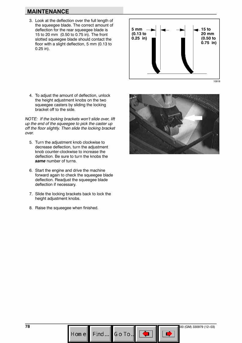
MAINTENANCE
7400 (GM) 330979 (12--03)78
3. Look at the deflection over the full length ofthe squeegee blade. The correct amount ofdeflection for the rear squeegee blade is15 to 20 mm (0.50 to 0.75 in). The frontslotted squeegee blade should contact thefloor with a slight deflection, 5 mm (0.13 to0.25 in).
4. To adjust the amount of deflection, unlockthe height adjustment knobs on the twosqueegee casters by sliding the lockingbracket off to the side.
NOTE: If the locking brackets won’t slide over, liftup the end of the squeegee to pick the caster upoff the floor slightly. Then slide the locking bracketover.
5. Turn the adjustment knob clockwise todecrease deflection, turn the adjustmentknob counter-clockwise to increase thedeflection. Be sure to turn the knobs thesame number of turns.
6. Start the engine and drive the machineforward again to check the squeegee bladedeflection. Readjust the squeegee bladedeflection if necessary.
7. Slide the locking brackets back to lock theheight adjustment knobs.
8. Raise the squeegee when finished.
10918
15 to20 mm(0.50 to0.75 in)
5 mm(0.13 to0.25 in)

MAINTENANCE
797400 (GM) 330979 (3--04)
LEVELING THE REAR SQUEEGEE
Leveling of the squeegee assures even contactover the length of the squeegee blade with thesurface being scrubbed. Make sure thisadjustment is done on an even, level floor.
1. Lower the squeegee and drive the machineforward.
2. Shut off the engine and set the machineparking brake.
FOR SAFETY: Before leaving orservicing machine; stop on levelsurface, set parking brake, turn offmachine and remove key.
3. Look at the deflection over the full length ofthe squeegee blade.
4. If the deflection is not the same over the fulllength of the blade, loosen the locking nut onthe two rear squeegee balljoints.
5. Turn the balljoint adjustment nut clockwise,from the rear of the machine, to increase thedeflection at the ends of the squeegee. Turnthe balljoint adjustment nutcounter-clockwise, from the rear of themachine, to decrease the deflection at theends of the squeegee blade.
6. Tighten the locking nuts.
7. Start the engine and drive the machineforward again to check the squeegee bladedeflection.
8. Readjust the squeegee blade deflection ifnecessary.

MAINTENANCE
7400 (GM) 330979 (3--04)80
SQUEEGEE BLADES
REAR SQUEEGEE
Check the squeegee blades for damage and weardaily. Rotate or replace either of the squeegeeblades if the leading edge is torn or worn half-waythrough the thickness of the blade.
The rear squeegee has two squeegee blades.Each blade has four wiping edges. To use themall, start with one wiping edge. To use the nextwiping edge, rotate the blade end-for-end. To usethe next wiping edge, rotate the top edges down,bottom edges up. To use the last edge, rotate theblade end-for-end.
Replace any worn or damaged squeegee blades.
REPLACING OR ROTATING REAR SQUEEGEEBLADES
1. Make sure the squeegee is raised off thefloor.
2. Shut the engine off and set the parkingbrake.
FOR SAFETY: Before leaving orservicing machine; stop on levelsurface, set parking brake, turn offmachine and remove key.
3. Open the retaining band clamp and removethe squeegee blade.

MAINTENANCE
817400 (GM) 330979 (3--04)
4. Replace or rotate the squeegee blade toallow a new edge to face the front of themachine.
5. Place the squeegee blade over the pins ofthe squeegee frame.
6. Position the retaining band over thesqueegee blade. Latch the retaining bandclamp.
7. Adjust the squeegee blade leveling anddeflection as stated in LEVELING THEREAR SQUEEGEE and ADJUSTING REARSQUEEGEE BLADE DEFLECTION.
SIDE SQUEEGEES
The side squeegees control water spray andchannel water into the path of the rear squeegee.Check the side squeegees for damage and weardaily. Replace the side squeegee bladeswhenever they become damaged or lose theirshape or resilience. Replace the squeegeedeflectors whenever they become worn.
REPLACING SIDE SQUEEGEE BLADES
1. Raise the scrub head.
2. Shut off the engine and set the machineparking brake.
FOR SAFETY: Before leaving orservicing machine; stop on levelsurface, set parking brake, turn offmachine and remove key.
3. Remove the cotter pin, clevis pin, deflector,and the retainer bracket from the front of theside squeegee.
4. Pull the squeegee blade out the front of thesqueegee frame.
5. Slide the new squeegee blade onto theframe.
NOTE: Lubricating the squeegee frame where thesqueegee makes contact will make it easier toinstall the squeegee blade.
6. Replace the retainer bracket, deflector,clevis pin, and cotter pin.
7. Repeat for the side squeegee on the otherside of the scrub head.
059420

MAINTENANCE
7400 (GM) 330979 (3--04)82
SIDE BRUSH SQUEEGEE
The side brush squeegee control water spray.Check the side brush squeegee for damage andwear daily. Replace the side squeegee bladeswhenever they become damaged or lose theirshape or resilience.
REPLACING THE SQUEEGEE BLADE
1. Raise the side brush.
2. Shut off the engine and set the parkingbrake.
FOR SAFETY: Before leaving orservicing machine; stop on levelsurface, set parking brake, turn offmachine and remove key.
3. Remove the side brush guard.
4. Remove the retainer clip from the end of thesqueegee.
5. Pull the squeegee blade out the front of thesqueegee frame.
6. Slide the new squeegee blade onto theframe.
NOTE: Lubricating the squeegee frame where thesqueegee makes contact will make it easier toinstall the squeegee blade.
7. Install the retainer clip on the end of thesqueegee.
8. Install the side brush guard.

MAINTENANCE
837400 (GM) 330979 (3--04)
SKIRTS AND SEALS
SCRUB HEAD SKIRTS
A skirt is mounted on each side of the scrub head.Check the skirts for wear or damage every100 hours of operation.
SIDE BRUSH SKIRT
The side brush skirt is located behind thesqueegee blade. Check the skirt for wear anddamage every 100 hours of operation.
COVER SEALS
Check the solution and recovery tank cover sealsfor wear or damage every 100 hours of operation

MAINTENANCE
7400 (GM) 330979 (3--04)84
BRAKES AND TIRES
SERVICE BRAKES
The mechanical service brakes are located on therear wheels. The brakes are operated by the footbrake pedal and connecting cables.
Check the brake adjustment every 200 hours ofoperation.
PARKING BRAKE
The parking brake is set with the parking brakepedal that activates the service brakes.
Check the parking brake adjustment every200 hours of operation.
TIRES
The machine tires are solid. Check the tires every100 hours of operation for damage.
FRONT WHEEL
Torque the front wheel nuts twice in the patternshown to 122 to 149 Nm (90 to 110 ft lb) after thefirst 50-hours of operation, and every 800 hoursthere after.
2
3
4
1
5

MAINTENANCE
857400 (GM) 330979 (3--04)
PUSHING, TOWING, AND TRANSPORTINGTHE MACHINE
PUSHING OR TOWING THE MACHINE
If the machine becomes disabled, it can bepushed from the front or rear, but towed only fromthe rear.
The propelling pump has a bypass valve toprevent damage to the hydraulic system when themachine is being pushed or towed. This valveallows a disabled machine to be moved for a veryshort distance and at a speed to not exceed 1.6kp/h (1 mph). The machine is NOT intended to bepushed or towed a long distance or at a highspeed.
ATTENTION! Do not push or towmachine for a long distance and withoutusing the bypass valve, or the machinehydraulic system may be damaged.
Turn the bypass valve 90_ from the normalposition before pushing or towing the machine.The illustration shows the bypass valve in thepushing or towing position.

MAINTENANCE
7400 (GM) 330979 (3--04)86
TRANSPORTING THE MACHINE
1. Position the rear of the machine at theloading edge of the truck or trailer.
2. If the loading surface is not horizontal or ishigher than 380 mm (15 in) from the ground,use a winch to load machine.
If the loading surface is horizontal AND is380 mm (15 in) or less from the ground, themachine may be driven onto the truck ortrailer.
3. To winch the machine onto the truck ortrailer, attach the winching chains in theholes at the bottom of the rear bumper.
If the machine has the optional rear tie downbrackets, attach the winching chains tothem.
4. Turn the bypass valve 90_ from the normalposition before winching the machine ontothe truck or trailer. See PUSHING ORTOWING THE MACHINE section of thismanual. Make sure the machine is centered.
FOR SAFETY: When loading machineonto truck or trailer, use winch. Do notdrive the machine onto the truck ortrailer unless the loading surface ishorizontal AND is 380 mm (15 in) or lessfrom the ground.

MAINTENANCE
877400 (GM) 330979 (3--04)
5. Position the machine onto the truck or traileras far as possible. If the machine starts toveer off the centerline of the truck or trailer,stop and turn the steering wheel to centerthe machine.
6. Set the parking brake and block the machinetires. Tie down the machine to the truck ortrailer before transporting.
The front tie down locations are in the holesat the bottom of the front bumper. If themachine has the optional tie down brackets,use them to tie down the machine.
The rear tie down locations are in the holesat the bottom of the rear bumper. If themachine has the optional rear tie downbrackets, use them to tie down the machine.
7. If the loading surface is not horizontal or ishigher than 380 mm from the ground, use awinch to unload machine.
If the loading surface is horizontal AND is380 mm (15 in) or less from the ground, themachine may be driven off the truck ortrailer.
FOR SAFETY: When unloading machineoff truck or trailer, use winch. Do notdrive the machine off the truck or trailerunless the loading surface is horizontalAND 380 mm or less from the ground.

MAINTENANCE
7400 (GM) 330979 (3--04)88
MACHINE JACKING
Empty the recovery and the solution tanks beforejacking the machine. You can jack up the machinefor service at the designated locations. Use a hoistor jack that will support the weight of the machine.Always stop the machine on a flat, level surfaceand block the tires before jacking the machine up.
FOR SAFETY: Before leaving orservicing machine; stop on levelsurface, set parking brake, turn offmachine and remove key.
The front jacking location is the left front corner ofthe machine frame.
The rear jacking locations are the two rear cornersof the machine frame.
FOR SAFETY: When servicing machine,block machine tires before jackingmachine up.
FOR SAFETY: When servicing machine,jack machine up at designated locationsonly. Block machine up with jackstands.
STORING MACHINE
Before storing the machine for an extended periodof time, the machine needs to be prepped tolessen the chance of rust, sludge, and otherundesirable deposits from forming. Contact yourTennant service personnel.

SPECIFICATIONS
897400 (GM) 330979 (12--05)
SPECIFICATIONS
GENERAL MACHINE DIMENSIONS/CAPACITIES
Item Dimension/capacity
Length 2460 mm (97 in)
Width 1525 mm (60 in)
Width with optional side brush 1600 mm (63.0 in)Height 1475 mm (58 in)
Height with overhead guard 2045 mm (80.5 in)
Main scrub brush diameter 280 mm (11 in)
Main scrub brush length 1145 mm (45 in)
Side scrub brush diameter (option) 405 mm (16 in)
Squeegee width 1525 mm (60 in)Scrubbing path width 1145 mm (45 in)
Scrubbing path width with optional side brush 1450 mm (57 in)
Debris tray volume capacity 42 L (1.5 ft3)
Solution tank 265 L (70 gal)
Recovery tank 273 L (72 gal)Detergent tank (option) 25 L (6.7 gal)
Total capacity with ES (option) 398 L (105 gal)
GVWR 2087 kg (4600 lb)
GENERAL MACHINE PERFORMANCE
Item Measure
Maximum forward speed 12.9 kmh (8 mph)
Maximum reverse speed 6.4 kmh (4 mph)
Minimum aisle turn width 3184 mm (125.5 in)
Minimum turning radius, right 2660 mm (104.75 in)
Minimum turning radius, left 2030 mm (79.75 in)
Maximum rated incline for scrubbing 6_
Maximum rated incline for transport of machine 8_
FaST SYSTEM
Item MeasureSolution pump 12 Volt DC, 11A, 11.6 LPM (3.0 GPM) open flow,
45 psi bypass setting
Low solution flow rate 2.7 LPM (0.7 GPM)
High solution flow rate 5.4 LPM (1.4 GPM)
Detergent pump 12 Volt DC
Low concentrate flow rate 2.6 CC/Minute (0.085 Liquid Ounces/Minute)
High concentrate flow rate 5.2 CC/Minute (0.17 Liquid Ounces/Minute)Air pump 12 Volt DC, 0.6 Maximum Amp draw
Air pump flow rate 8.7 LPM (0.3 CFM) open flow

SPECIFICATIONS
7400 (GM) 330979 (5--07)90
POWER TYPE
Engine Type Ignition Cycle Aspiration Cylinders Bore StrokeGM 1.6 Piston Distributorless-
type spark4 Natural 4 79 mm
(3.11 in)81.5 mm(3.21 in)
Displacement Net power, governed Net power, maximum1600 cc (98 cu in) 27.75 kw (37 hp) @ 2400 rpm 41.25 kw (55 hp) @ 4000
rpmFuel Cooling system Electrical systemGasoline, 87 octaneminimum, unleaded.Fuel tank: 42 L (11.2 gal)
Water/ethylene glycolantifreeze
12 V nominal
LPG,F l t k 15 k (33 lb)
Total: 7.5 L (2 gal) 75 A alternator,Fuel tank: 15 kg (33 lb) Radiator: 3.8 L (1 gal)Idle speed, no load (Fast) governed speed,
under loadFiring order
950 + 50 rpm 2400 + 50 rpm 1--3--4--2,Spark plug gap Valve clearance, cold Engine lubricating oil with filter1 mm (0.04 in) No Adjustment
OHC Engine3.5 L (3.7 qt) 5W30SAE--SG/SH
STEERING
Type Power source Emergency steering
Front wheel, hydraulic cylinder and rotaryvalve controlled
Hydraulic accessory pump Manual
HYDRAULIC SYSTEM
System Capacity Fluid Type
Hydraulic reservoir 38 L (10 gal) TENNANT part no. 65869 -- above 7_ C (45_ F)
Hydraulic total 74 L (19.5 gal) TENNANT part no. 65870 -- below 7_ C (45_ F)
BRAKING SYSTEM
Type Operation
Service brakes Mechanical drum brakes (2), one per rear wheel, cable actuated
Parking brake Utilize service brakes, cable actuated
TIRES
Location Type Size Pressure
Front (1) Solid 460 x 130 mm (5 x 18 in) --
Rear (2) Solid 460 x 130 mm (5 x 18 in) --

SPECIFICATIONS
917400 (GM) 330979 (3--04)
1327 mm(52.25 in)
2460 mm(97 in)
2045 mm(80.5 in)
1475 mm(58 in)
1525 mm(60 in)
1260 mm(49.6 in)
1610 mm(63.4 in)
1483 mm(58.4 in)
1686 mm(66.4 in)
10919
MACHINE DIMENSIONS

SPECIFICATIONS
7400 (GM) 330979 (3--05)92