Gas Lift
42
Gas Lift • Methods • Limitations • Gas lift is the incorporation of externally supplied gas, injected into the flow stream at specific depths, to decrease the produced fluid flowing density and create a higher drawdown on the formation, resulting in higher production. 8/25/2015 1 George E. King Engineering GEKEngineering.com
-
Upload
kevin-steinbach -
Category
Documents
-
view
11 -
download
2
description
N/A
Transcript of Gas Lift
Gas Lift
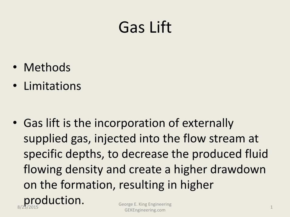
• Methods
• Limitations
• Gas lift is the incorporation of externally supplied gas, injected into the flow stream at specific depths, to decrease the produced fluid flowing density and create a higher drawdown on the formation, resulting in higher production.
8/25/2015 1
George E. King Engineering GEKEngineering.com

Continuous Flow Gas Lift: Applications
• Producing wells that cannot flow naturally.
• Increasing production in flowing wells.
• Lift wells that flow solids.
• To initiate flow in wells with too much liquid column or saturation to
start flowing.
• Unloading gas wells and deliquification.
• To assist backflow of injectors and disposal wells.
• Produce water source wells.
8/25/2015 2 George E. King Engineering
GEKEngineering.com

Gas Lift
• Advantages – No restrictions in tubing
– Can use subsurface safety valves with only minor complications.
– Will lift sand laden fluids
– Flexible and changeable conditions, can be optimized
– Can be used in deviated wells (looses efficiency with increasing deviations)
– Works with reservoir gas, any GOR
– Low Capex and Opex.
– Requires minimum surface space
– Does not need electrical power.
• Disadvantages – Efficiency is lowest of common lift
methods. – Low pressure wells will produce
better with other lift methods. – Loses efficiency as deviation goes
beyond about 15 to 20o – requires more gas.
– Low gas volume may be a drawback, requiring more gas volume.
– Must have a high pressure gas source (high enough for lift)
– Will not work well with low API oils (gas expansion cools the fluid)
8/25/2015 3 George E. King Engineering
GEKEngineering.com
Gas Lift Basics
• Continuous gas lift simply supplements the natural flow process by adding additional gas into the produced fluid to reduce the hydrostatic head component and hence, the back pressure on the formation.
8/25/2015 4 George E. King Engineering
GEKEngineering.com

Gas Lift Basics
• Injection gas is supplied in a closed loop system, in which it is collected from the separators, then compressed, dried (if necessary), and supplied to the well.
• The lift gas is normally injected down the annulus and into the tubing through a gas lift valve (GLV), which contains a non-return check valve.
• Advantageous to locate the lift point as low as possible in the well to lighten as much head as possible.
• Generally only flows gas from one valve at a time.
8/25/2015 5 George E. King Engineering
GEKEngineering.com
Gas Lift Limits
• The gas supply pressure.
• The flowing pressure in the tubing at the valve – ensure adequate pressure and stable supply.
• The depth of the deepest gas lift mandrel.
• The differential across the valves required to keep the upper valves closed
• Well deviation – fluid segregation is a severe limit
8/25/2015 6 George E. King Engineering
GEKEngineering.com
Gas Lift Design
• The available kick-off pressure gradient is first plotted on the graph. Kick-off pressure is usually higher than normal GL operating system pressure
• Kill fluid gradient is plotted starting at the flowing tubing head pressure of the production system.
• The intersection of the kill gradient with the kick-off pressure gradient determines the location of the first GLV.
8/25/2015 7 George E. King Engineering
GEKEngineering.com
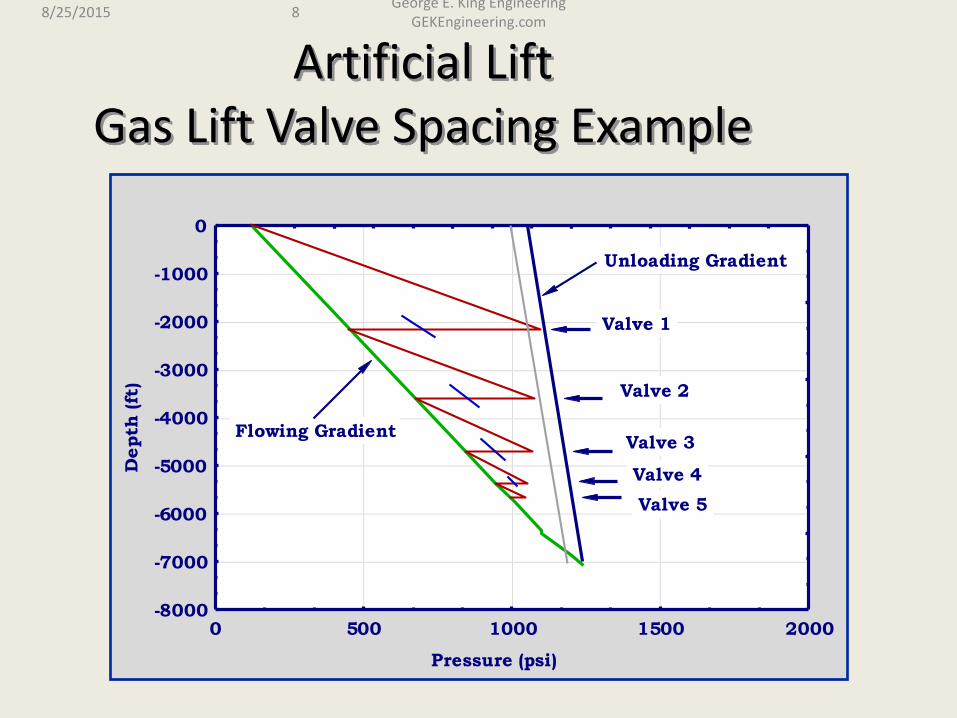
Artificial Lift Gas Lift Valve Spacing Example
Pressure (psi)
Depth
(ft
)
-8000
-7000
-6000
-5000
-4000
-3000
-2000
-1000
0
0 500 1000 1500 2000
Valve 1
Valve 2
Valve 3
Valve 4
Valve 5
Flowing Gradient
Unloading Gradient
8/25/2015 8 George E. King Engineering
GEKEngineering.com

Gas Lift Operation
• Gas passes through the first GLV and lightens the fluid column in the tubing.
• As tubing fluid gradient changes, supply gas in the casing moves down to second GLV, unloading fluid from casing & lightening the flowing fluid above the second valve.
• The process continues until the fluids in the casing annulus have been displaced, and the gas is passing through the bottom valve.
8/25/2015 9 George E. King Engineering
GEKEngineering.com
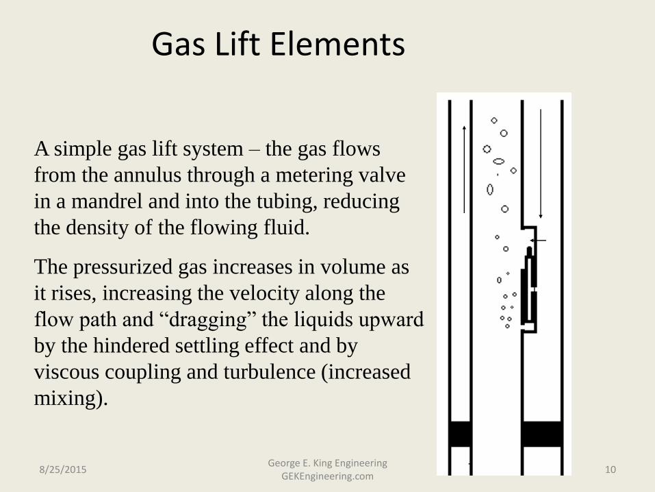
A simple gas lift system – the gas flows
from the annulus through a metering valve
in a mandrel and into the tubing, reducing
the density of the flowing fluid.
The pressurized gas increases in volume as
it rises, increasing the velocity along the
flow path and “dragging” the liquids upward
by the hindered settling effect and by
viscous coupling and turbulence (increased
mixing).
Gas Lift Elements
8/25/2015 10 George E. King Engineering
GEKEngineering.com
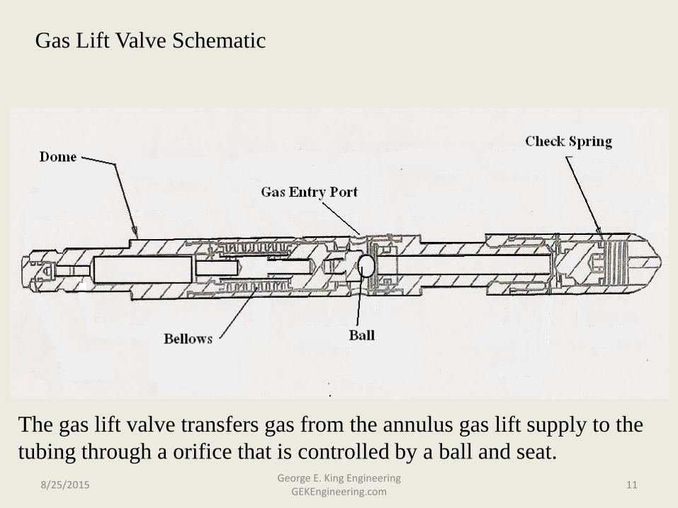
Gas Lift Valve Schematic
The gas lift valve transfers gas from the annulus gas lift supply to the
tubing through a orifice that is controlled by a ball and seat.
8/25/2015 11 George E. King Engineering
GEKEngineering.com
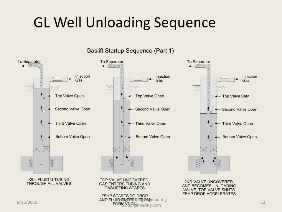
GL Well Unloading Sequence
8/25/2015 12 George E. King Engineering
GEKEngineering.com

G. L. Well Unloading Sequence Part 2
8/25/2015 13 George E. King Engineering
GEKEngineering.com

Gas Lift – final comments
• Production rate from a gas lifted well is a function of: – reservoir pressure,
– PI,
– water cut
– gas injection rate
– valve placement – this is frequently a limit because an insufficient number of G.L. mandrels were used when tubing was run.
8/25/2015 14 George E. King Engineering
GEKEngineering.com

Lift – when needed?
• When pressures decline.
• When tubing large/gas rate drops (wells loading).
• When water hits.
• To enhance production.
8/25/2015 15 George E. King Engineering
GEKEngineering.com
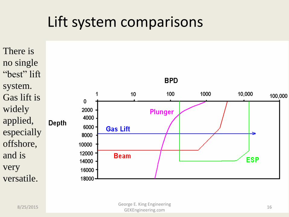
There is
no single
“best” lift
system.
Gas lift is
widely
applied,
especially
offshore,
and is
very
versatile.
Lift system comparisons
8/25/2015 16 George E. King Engineering
GEKEngineering.com
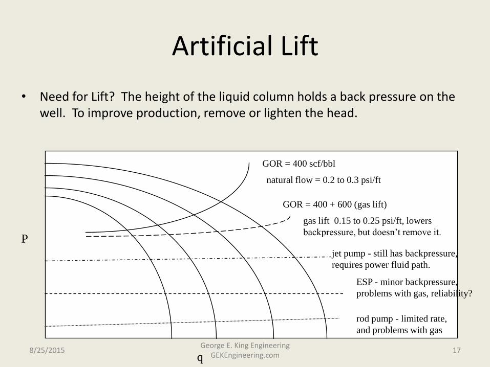
Artificial Lift
• Need for Lift? The height of the liquid column holds a back pressure on the well. To improve production, remove or lighten the head.
q
P
GOR = 400 scf/bbl
GOR = 400 + 600 (gas lift)
rod pump - limited rate,
and problems with gas
ESP - minor backpressure,
problems with gas, reliability?
jet pump - still has backpressure,
requires power fluid path.
gas lift 0.15 to 0.25 psi/ft, lowers
backpressure, but doesn’t remove it.
natural flow = 0.2 to 0.3 psi/ft
8/25/2015 17 George E. King Engineering
GEKEngineering.com

Gas Lift
• Advantages
– Mandrels 5 to 7 ft long - can go around corners
– Lift large amounts of solids
– Lift very large amounts of liquids
Pennwell AL Charts, 1986 8/25/2015 18 George E. King Engineering
GEKEngineering.com
Gas Lift
• Disadvantages – limited by lowest hydrostatic column you can
generate with gas mix, usually 0.15 to 0.25 psi/ft, cannot draw it down all the way.
– Stratification of gas to high side - solids dropped, gas slugs in highly deviated wells and in any horizontal flow. System less efficient as deviation goes beyond 15 to 20o deviation from vertical.
– Takes a lot of gas near depletion to lift gas depleted reservoir fluid.
8/25/2015 19 George E. King Engineering
GEKEngineering.com
GL Solutions
• keep GL valves near vertical
• use tapered string
• recalculate gas lift requirements on a regular basis
• A gas lift engineer is needed on a full time basis to optimize big fields.
8/25/2015 20 George E. King Engineering
GEKEngineering.com
Gas Lift Valve Testing
• Have to know how valve performs to be able to model the lift system.
• Determine if the valve is performing as expected
• how much actual flow comes through the valve
• How to use the test data
8/25/2015 21 George E. King Engineering
GEKEngineering.com

Types
• Static
– Load rate
– travel
– opening and closing
• Dynamic
– flow coefficients
– live valve flow test
8/25/2015 22 George E. King Engineering
GEKEngineering.com

Factors affecting GL valve performance
• 1. Max effective stem travel (less than 1/16” to 0.18”) - must balance port size with travel to get performance. Some valves might be throttling while others may be wide open.
• 2. The load rate of a valve is a measure of the valves’ resistance to opening. The higher the load rate, the more pressure pressure required to move the stem off the seat.
– Load rate of a 1” IPO valve is about 1000 psi/inch
8/25/2015 23 George E. King Engineering
GEKEngineering.com
Factors affecting GL valve performance
• 3. Flow coefficients are a measure of the valve’s resistance to flow. Valves with high flow coefficients curves have high flow rates. Flow coefficients are geometry dependent and cannot be changed.
– The shape of the flow path through the valve determines the flow coefficient.
8/25/2015 24 George E. King Engineering
GEKEngineering.com

Factors affecting GL valve performance
• 4. Silicon fluid is used in the bellow (dome) to dampen vibrations. Silicon fluid expands with temperature and causes the dome pressure to increase more than the normal temperature correlation.
– Problem is than if one valve in the string has a different ratio of fluid to dome size - it will behave differently - may not close.
– Can be bad problem on refurbished valves
8/25/2015 25 George E. King Engineering
GEKEngineering.com
How can you use valve performance data?
• Use VPC data to:
– calculate gas flow rates through the valves - get a performance curve for the pressure conditions in force.
– perform troubleshooting
– use in computer prog to dynamically simulate a gas lift well.
8/25/2015 26 George E. King Engineering
GEKEngineering.com
Field (BP Forties) Optimization in the North Sea
• Gas, natural lift, artificial lift, commitment
• Well-by-well review – use of analysis software
– model individual wells
– monitor performance
– scrutinize individual wells downhole/ surface
– consider whole production system
– troubleshoot problematic wells
– evaluate recommended actions
8/25/2015 27
George E. King Engineering GEKEngineering.com
Continued…..
• Full Field Optimization
– model network
– model reservoir
– set up and model management system
– train operator engineers
– train personnel
– manage field optimization
– measure performance
8/25/2015 28 George E. King Engineering
GEKEngineering.com
Unlocking Value – Optimization of the lift system!
• Optimization leads to peaks in production - problem is making constant changes that keeps the production high.
• Peaks show potential value from optimization – rate will fall off fast if gas lift system is left alone.
8/25/2015 29 George E. King Engineering
GEKEngineering.com

Considerations
• Sand production
• drawdown limitations
• produced water handling
• water coning/preferential production
• scale
• gas capacity and availability
• plant considerations
• well start up philosophies
8/25/2015 30 George E. King Engineering
GEKEngineering.com
Optimization Procedure
• Focused and regular scrutiny of wells
• reconcile differences and take action
• input data into full field model
• compare actual with predicted
• run full field optimized model
• construct working document
• longer term issues go to management mtg
• report weekly figures
• monitor against measures
• support artificial lift studies
8/25/2015 31 George E. King Engineering
GEKEngineering.com

When do you need lift? • Do an Inflow Performance Relationship (IPR)
analysis
• Do a nodal analysis on the effect of back pressure.
• Look for slugging, surging effects in the facilities or on the instrumentation of the well.
• Will adding lift make an economic impact on production?
• What type of lift will create the best value? What lift system will the will the well and field conditions support?
8/25/2015 32 George E. King Engineering
GEKEngineering.com

Effect o f G as R ate on B H P
0
500
1000
1500
2000
2500
3000
0 500 1000 1500
Nitro g en Rate , sc f/m in
BH
P a
t 6
90
0 f
t, p
si
Friction Dominated
Hydrostatic
Dominated
Just adding more gas will not always increase lift.
8/25/2015 33 George E. King Engineering
GEKEngineering.com

Lift Systems
• gas lift - 95% of offshore lift systems
• rod pumps - shallower (d<11,000’ TVD), lower volume (rod breakage and problems increase with depth).
• ESP’s - high volume, high mantainence
8/25/2015 34 George E. King Engineering
GEKEngineering.com
Gas Lift
• operating depth limited by supply pressure
• would like to inject as deep as possible
• lift limited by the flowing gradient
– depth of gas lift injection
– amount of gas injected (back pressures)
– mixing of gas with liquid
– density of fluid to be lifted
8/25/2015 35 George E. King Engineering
GEKEngineering.com
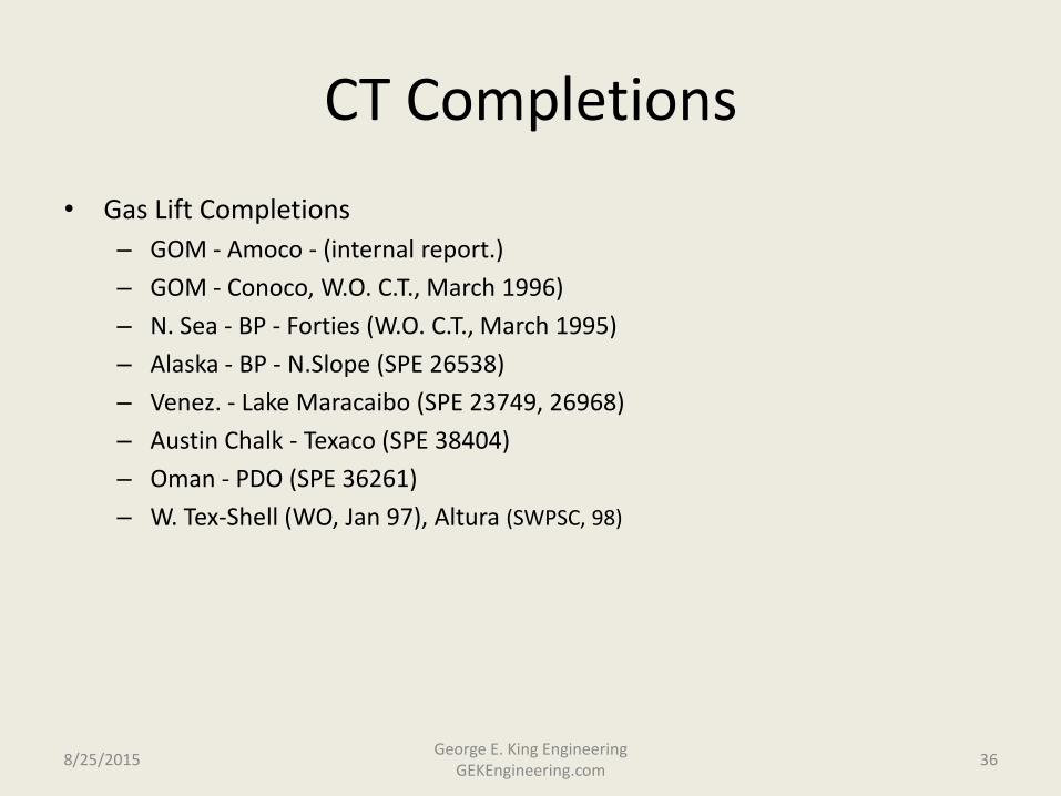
CT Completions
• Gas Lift Completions
– GOM - Amoco - (internal report.)
– GOM - Conoco, W.O. C.T., March 1996)
– N. Sea - BP - Forties (W.O. C.T., March 1995)
– Alaska - BP - N.Slope (SPE 26538)
– Venez. - Lake Maracaibo (SPE 23749, 26968)
– Austin Chalk - Texaco (SPE 38404)
– Oman - PDO (SPE 36261)
– W. Tex-Shell (WO, Jan 97), Altura (SWPSC, 98)
8/25/2015 36 George E. King Engineering
GEKEngineering.com

Flow Velocity and Lift
• Flow velocity affects flow efficiency through liquid slippage, turbulence and friction.
• At low rates, gas tends to slip through liquids, allowing the liquids to remain in the tubing.
• At medium rates, gas drags liquid upward due to turbulence. This action reduces pressure gradient.
• At very high flow rates, friction of flowing fluid with the wall of the tubing causes excessive pressure drops, increasing the flowing gradient.
8/25/2015 37 George E. King Engineering
GEKEngineering.com
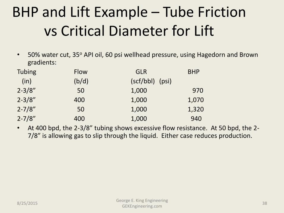
BHP and Lift Example – Tube Friction vs Critical Diameter for Lift
• 50% water cut, 35o API oil, 60 psi wellhead pressure, using Hagedorn and Brown gradients:
Tubing Flow GLR BHP
(in) (b/d) (scf/bbl) (psi)
2-3/8” 50 1,000 970
2-3/8” 400 1,000 1,070
2-7/8” 50 1,000 1,320
2-7/8” 400 1,000 940
• At 400 bpd, the 2-3/8” tubing shows excessive flow resistance. At 50 bpd, the 2-7/8” is allowing gas to slip through the liquid. Either case reduces production.
8/25/2015 38 George E. King Engineering
GEKEngineering.com
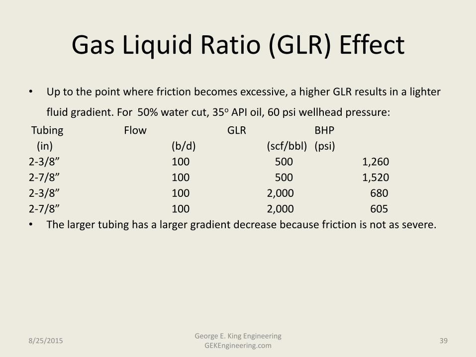
Gas Liquid Ratio (GLR) Effect
• Up to the point where friction becomes excessive, a higher GLR results in a lighter
fluid gradient. For 50% water cut, 35o API oil, 60 psi wellhead pressure:
Tubing Flow GLR BHP
(in) (b/d) (scf/bbl) (psi)
2-3/8” 100 500 1,260
2-7/8” 100 500 1,520
2-3/8” 100 2,000 680
2-7/8” 100 2,000 605
• The larger tubing has a larger gradient decrease because friction is not as severe.
8/25/2015 39 George E. King Engineering
GEKEngineering.com

Wellhead Pressures
• A small increase in wellhead pressure (WHP) can have a very severe change on BHP. Data for 2-3/8” tbg.
Flow GLR Flowing WHP Flowing BHP
(b/d) (scf/bbl) (psi) (psi)
200 200 50 990
200 200 80 1,155
• An increase in 30 psi at surface results in a 165 psi increase in flowing BHP.
• In most cases, the choke setting (the backpressure on the system) should be as low as possible. If gas volume is increasing too much (creating backpressure), then the system is not efficient. A small choke change may help reduce gas volume slightly and actually improve lift.
• How do you optimize a choke with a minimum of equipment?
8/25/2015 40 George E. King Engineering
GEKEngineering.com
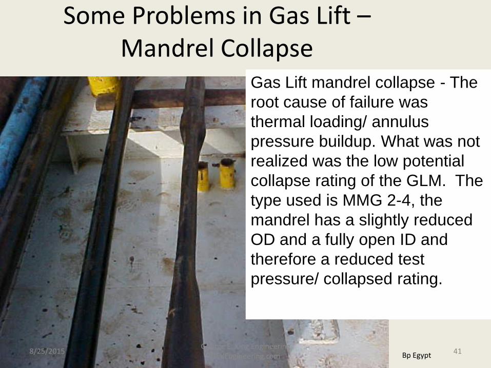
Gas Lift mandrel collapse - The
root cause of failure was
thermal loading/ annulus
pressure buildup. What was not
realized was the low potential
collapse rating of the GLM. The
type used is MMG 2-4, the
mandrel has a slightly reduced
OD and a fully open ID and
therefore a reduced test
pressure/ collapsed rating.
Some Problems in Gas Lift – Mandrel Collapse
Bp Egypt 8/25/2015 41 George E. King Engineering
GEKEngineering.com
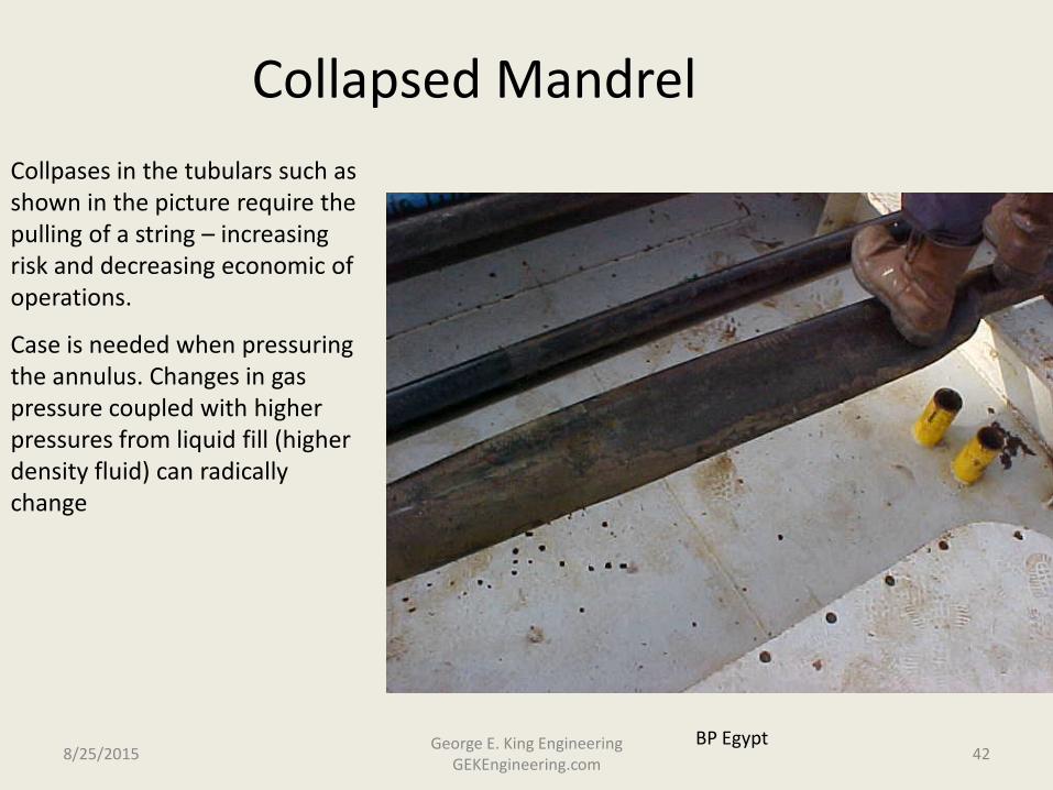
Collapsed Mandrel
BP Egypt
Collpases in the tubulars such as shown in the picture require the pulling of a string – increasing risk and decreasing economic of operations.
Case is needed when pressuring the annulus. Changes in gas pressure coupled with higher pressures from liquid fill (higher density fluid) can radically change
8/25/2015 42 George E. King Engineering
GEKEngineering.com