
Gas Detection & Alarm Systems - New Cosmos Electric … processes the signals from the detector. It...
32
PRODUCT GUIDE Gas Detection & Alarm Systems for Industrial Use
Transcript of Gas Detection & Alarm Systems - New Cosmos Electric … processes the signals from the detector. It...

PRODUCT GUIDE
Gas Detection & Alarm Systems for Industrial Use
1
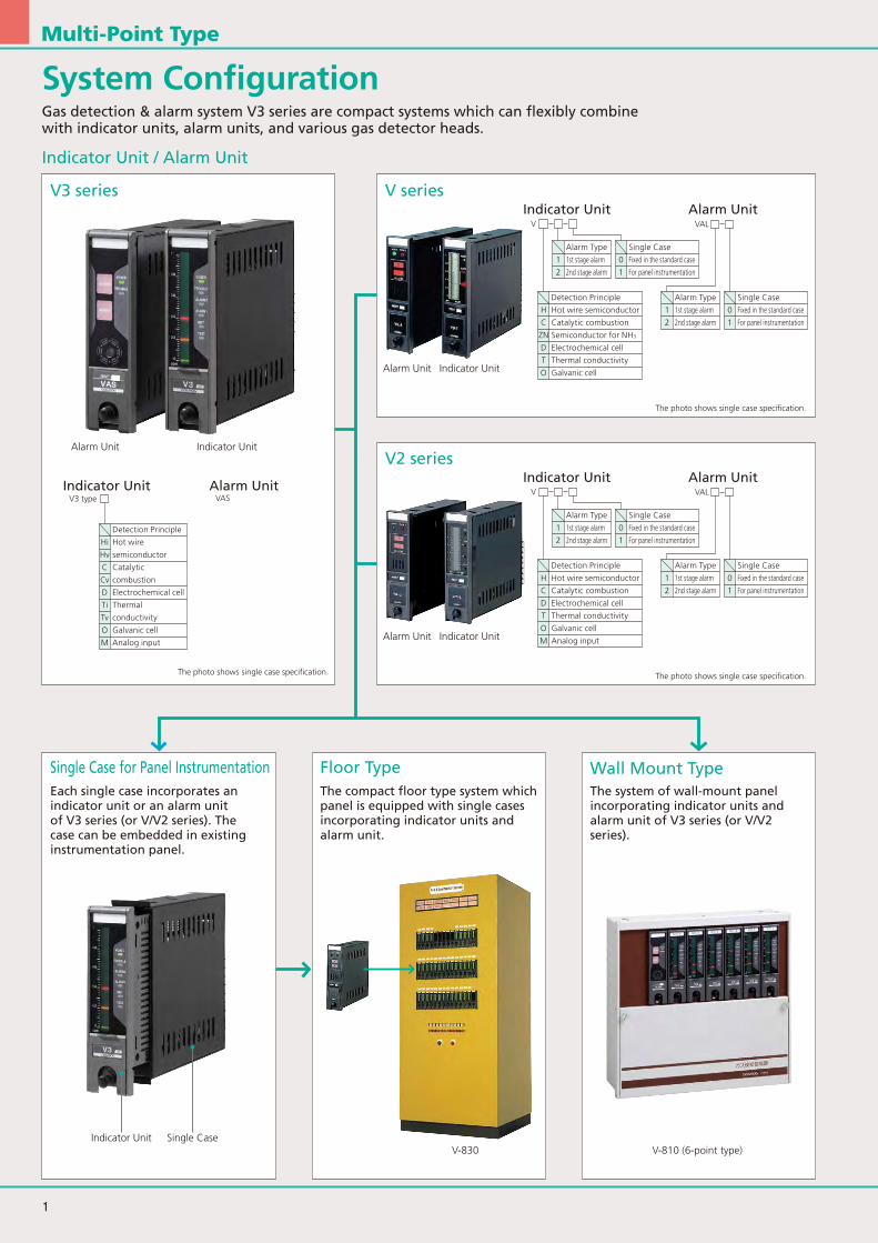
V3 series
Single Case for Panel Instrumentation Floor Type Wall Mount Type
V series
V2 series
Indicator Unit
Each single case incorporates an indicator unit or an alarm unit of V3 series (or V/V2 series). The case can be embedded in existing instrumentation panel.
The compact floor type system which panel is equipped with single cases incorporating indicator units and alarm unit.
The system of wall-mount panel incorporating indicator units and alarm unit of V3 series (or V/V2 series).
Indicator Unit
Indicator UnitAlarm Unit
Alarm Unit
Alarm Unit
Alarm Unit
Alarm Unit
Alarm Unit
Indicator Unit Single CaseV-830 V-810 (6-point type)
Indicator Unit
Indicator Unit
Indicator Unit
Detection Principle
H Hot wire semiconductor
C Catalytic combustion
ZN Semiconductor for NH3
D Electrochemical cell
T Thermal conductivity
O Galvanic cell
Detection Principle
H Hot wire semiconductor
C Catalytic combustion
D Electrochemical cell
T Thermal conductivity
O Galvanic cell
M Analog input
Detection Principle
Hi Hot wire
Hv semiconductor
C Catalytic
Cv combustion
D Electrochemical cell
Ti Thermal
Tv conductivity
O Galvanic cell
M Analog input
Alarm Type
1 1st stage alarm
2 2nd stage alarm
Alarm Type
1 1st stage alarm
2 2nd stage alarm
Alarm Type
1 1st stage alarm
2 2nd stage alarm
Alarm Type
1 1st stage alarm
2 2nd stage alarm
Single Case
0 Fixed in the standard case
1 For panel instrumentation
Single Case
0 Fixed in the standard case
1 For panel instrumentation
Single Case
0 Fixed in the standard case
1 For panel instrumentation
Single Case
0 Fixed in the standard case
1 For panel instrumentation
VAS
The photo shows single case specification.
The photo shows single case specification.
The photo shows single case specification.
Multi-Point Type
System ConfigurationGas detection & alarm system V3 series are compact systems which can flexibly combine with indicator units, alarm units, and various gas detector heads.
Indicator Unit / Alarm Unit
VAL
VAL
V
VV3 type

2
typeHi
typeCi
typeTi
typeO
typeM
VZN
typeD
typeHv
typeCv
typeTv
V3
V3
V3
V3
V3
V3
V3
V3
V3
VH
VC
VT
VO V2O
VD V2D
V2M
V2H
V2C
V2T
KD-2A · KD-3A · KD-14
KD-2A · KD-3A
KD-2A · KD-3A
KS-2O · KD-5O
KD-8 · KD-12 series · KS-7 series
KD-2AS
KCM-3A · KD-5D · KS-2D
KD-5A · KD-5B
KD-5A · KD-5B
KD-5A · KD-5B
PD-14 · PE-2CC · PE-2DC
PD-14 · PE-2CC · PE-2DC
PE-2CC · PE-2DC
PS-2OE
PS-4OP · PS-2OP
PD-8F · PD-8N · PS-2 I · PS-6DKPPS-7 series · IRC seriesPD-12 series
PE-2CZ
PS-2DE
PS-2DP · PS-2CD · PS-2CK IIIPS-2DKP · PS-2DPS · PS-4DP
PD-5F · PD-5N · PS-4HP
PD-5F · PD-5N
PD-5F · PD-5N
Diffusion/Eductor
Diffusion/Eductor
Diffusion/Eductor
Diffusion
Diffusion
Diffusion/Eductor
Diffusion
Diffusion/Eductor
Diffusion/Eductor
Diffusion/Eductor
Extractive
Extractive
Diffusion/Eductor
Eductor
Extractive
Extractive
Extractive
Eductor
Extractive
Extractive
Extractive
Diffusion/Eductor
Hot wire semiconductor sensor
Catalytic combustion
Thermal conductivity
For 4-20mA/DC input
Semiconductor for NH3
Hot wire semiconductor sensor
Catalytic combustion
Thermal conductivity
Combustible gas(LPG, CH4, etc.)
Combustible gas(LPG, CH4, etc.)
H2, Helium, Argon, CO2, CH4
NH3
Electrochemical cell Semiconductor manufacturing gas/ Toxic gas
Combustible gas(LPG, CH4, etc.)
Combustible gas(LPG, CH4, etc.)
H2, Helium, Argon, CO2, CH4
Combustible gas/ For ppm
Combustible gas/ For %LEL
Inert gas/ For vol%
Oxygen
For analog output
NH3
Toxic gas
Model Sampling Method Detection Principle Target Gas
Galvanic cell O2
Multi-Point Type
Indicator Unit Model Applicable Detector Head

3
V3 series
Outline
Indicator Unit/ Alarm UnitAn indicator unit supplies power to the gas detector head and processes the signals from the detector. It displays the gas concentration in 3-color LED bar-graph, it will activate the alarm automatically at alarm set value and transmit the signals to the alarm unit and external output devices (contact output, analog output).
The alarm unit receives the signals (non-contact output) from V3 series indicator unit, displays the alarm (buzzer and lamp), and outputs control contacts to external devices.
Part Names
FEATURES
1st Stage Alarm 2nd-Stage Alarm
Easy to notice the alarm status with 3-color LED display.Maintenance Mode which will stop the alarm output to external devices during the maintenance, to allow a maintenance work alone.It can be replaced in the existing COSMOS gas detection system due to the failures. The cover attachment of PCB makes safe to use.The switch cover prevents accidental operation.The switch cover for alarm unit can also be selected (option).
Adjustment Button
Test ButtonHIGH Button
Maintenance Button
LOW Button
Multi-Point Type
The digital bar-graph of indicator unit will inform alarm, along with lamp and buzzer. The color of bar graph will turn orange at 1st stage alarm, and red at 2nd stage alarm.
POWER Lamp
ALARM2 (2nd stage alarm) Lamp
2nd Stage Alarm Lamp
1st Stage Alarm Lamp
TROUBLE Lamp
ALARM1 (1st stage alarm) Lamp
1st Stage Alarm Lamp
Reset Button
ALARM UNITINDICATOR UNIT
Bar Graph (gas concentration)
TAG Number Plate

4
Multi-Point Type
TypeGas Concentration Display
AlarmIndication
Alarm Set Value
Alarm Accuracy
Response Time
External Output
Power Source
Power Consumption
Other Functions
Operating TemperatureDimensionsWeight
Hv, Hi, Cv, Ci, Tv, Ti, D, O3-color LED bar graph (50 split)Normal: Green POWER lamp lights up, Initial energization: Green POWER lamp flashes for 30s.Red ALARM lamp flashes (lights up on reset)Yellow TROUBLE lamp flashesAdjustable within the detection range for 1st and 2nd stage alarm.Combustible gas: Within +/-25% of alarm set valueToxic gas: Within +/-30% of alarm set valueOxygen: Within +/-1.0vol% of alarm set valueCombustible gas: Within 30s at 160% concentration of alarm set valueToxic gas: Within 60s at 160% concentration of alarm set valueOxygen: Within 5s at 10vol% (oxygen deficiency)1c no-voltage (100V AC/ 1A resistance load, 24V DC, 1A-resistance load), 1a for trouble contact4 - 20mA DC24V DC +/-10%
Approx. 5.0W (excluding power consumption of extractive gas detector)
Linearization, maintenance mode, zero suppression[Option] Peak hold function, alarm delay, low flow rate alarm function (can be set by connecting detector)-10 to 40 degrees C, 10 to 90%RHW36×H144×D70 mm (excluding protrusions)Approx. 600g (including 450g single case)
Model
Model VH/V2H VC/V2C VZN VD/V2D VT / V2T VO/V2O VM/V2M
Depends on the detector specificationsLCD bar graphAdjustable within the detection range Combustible gas: Within +/-25% of alarm set valueToxic gas: Within +/-30% of alarm set valueOxygen: Within +/-1.0vol% of alarm set valueCombustible gas: Within 30s at 160% gas concentration of alarm set valueToxic gas: Within 60s at 160% concentration of alarm set valueOxygen: Within 5s at 10vol% (oxygen deficiency)Normal: Green POWER lamp lights up, Trouble: Off, Initial energization: Green POWER lamp flashes for 30s.Alarm: Red lamp flashes, Lights up by reset, latching type (standard. Non-latching can be specified)1c no-voltage (100V AC/ 1A resistance load), 1a for trouble contact4-20mA (standard), 0-100mV and 1-5V (option *1), Digital Output (option)Approx. 30s delay is available (option)-10 to 40 degrees C24V DC +/-10%Approx. 5WW36× H144×D150 mmApprox. 650g (including 450g single case)
Hot wireSemiconductor
Combustible gas
CatalyticCombustion
Combustible gas
Semiconductor for NH3
NH3
Electrochemical cell
Specialty gasesVarious toxic gases
Thermal ConductivityH2, Helium, Argon,CO2, CH4 etc.
Galvanic cell
O2
Analog
4-20mA DC input
−
−
V3 Series Specifications
V/ V2 Series Specifications
Indicator UnitV3
Model
Number of Alarm StageConnectable Indicator UnitPower Lamp
Alarm Indication
External Output
Power SourcePower Consumption
Other Functions
Operating TemperatureDimensionsWeight
VAS
2 stagesV3 seriesGreen POWER lamp lights upRed ALARM lamp lights up (normally off)Yellow TROUBLE alarm lights up (normally off)Alarm: intermittent sound, Trouble: continuous sound (more than 70dB(A)/m)1c no-voltage for 1st and 2nd stage alarm (100V AC, 1A-resistance load)1a no-voltage (100V AC/ 1A resistance load, 24V DC, 1A-resistance load)1a no-voltage (100V AC/ 1A resistance load, 24V DC, 1A-resistance load)24V DC +/-10%Approx. 3.5W (24V for alarm)Complete lock type (to be specified)With the operation button cover (to be specified)-10 to 40 degrees C, 10 to 90%RHW36×H144×D70 mm (excluding protrusions)Approx. 600g (including 450g single case)
Alarm Unit
Detection Principle
Target Gas
Detection RangeGas Concentration DisplayAlarm Set Value
Alarm Accuracy
Response Time
Alarm IndicationExternal OutputAlarm Delay CircuitOperating TemperaturePower SourcePower ConsumptionDimensionsWeight
V2 series
V series
M
Depends on the detector head specifications
Depends on the detector head specifications
Approx. 5.0W (excluding power consumption of detector)
Power LampAlarm LampContact OutputAnalog Output
Power LampAlarm LampTrouble Lamp
Contact OutputAnalog Output
Alarm LampTrouble LampBuzzerAlarm ContactTrouble ContactBuzzer Contact
* The above specifications inlude single case.* V2 series have additional functions of indicator backlight, maintenance mode as standard.*1: V2 series are not capable of 0-10mA analog output.

5
PD-14
KD-14
PD-14
PD-14
KD-14
PD-14
KD-14
V-830
Alarm unit dimensions Panel cutout dimensions
Indicator unit dimensions
Terminal arrangements
Terminal arrangements
KD-14
Single Case (V3 series)
V-830
For Panel Instrumentation
Floor Type
Outline Use exampleV-830 gas detector is a compact floor type system of which panel is equipped with single cases incorporating indicator units and an alarm unit, and is best suited for multi-point monitoring.
Multi-Point Type

6
Unit: millimeter
342
A 93 1021
UV-810 gas detector is a compact system of wall (panel) mount type which combines indicator units, an alarm unit, and various gas detector heads of the V3 series.Detects combustible gases, toxic/specialty gases, and oxygen (oxygen deficiency) and gives an alarm signal when the gas concentration goes over a set value (or under a set value for oxygen deficiency), so as to prevent gas accidents such as gas explosion, poisoning, and oxygen deficiency.UVB-810 incorporates a backup power supply unit.
Dimensions (UV-810)
UV-810 UVB-810Wall (Panel) Mount Type
Outline
Specifications
FEATURESCompact design.Standard cases for 3/6/9/12/15 points are available.Wide variety of input power sources.Can be equipped with a Zener barrier.Combination of the V3 series (or V/V2 series) units allows detection of and alarm for various gases.
Model UV-810Up to 15-point (lineup: 3-point type, 6-point type, 9-point type, 12-point type and 15-point type)As per gas detector: · Combustible Gas : within 25% of alarm value under an identical condition · Toxic Gas: within 30% of alarm value under an identical condition Indicator Unit · Alarm Lamp: Blinks on alarm, lights up by reset, latching (or non-latching)Alarm Unit · Trouble Lamp: RED lamp lights up (1st stage, 2nd stage) when at least one indicator unit is activated Yellow lamp lights up when at least one indicator unit cause a malfunction · Alarm Buzzer: Intermittent alarm when at least one indicator unit is activated Continuous alarm when at least one indicator unit cause a malfunction Terminal for Collective Alarm · 2nd Alarm Contact: 1a non-voltage (STD) (100V AC, 1A. 24V DC, 1A load resistance) · 1st Alarm Contact: 1a non-voltage (STD) (100V AC, 1A. 24V DC, 1A load resistance) · Buzzer Contact: 1a non-voltage (STD) (100V AC, 1A. 24V DC, 1A load resistance) · Trouble Contact: 1a non-voltage (STD) (100V AC, 1A. 24V DC, 1A load resistance) * Collective alarm contacts of 1st alarm and 2nd alarm can be changed to 1b contact (need to specify)Terminal for Individual Alarm · 2nd Alarm Contact: 1a non-voltage (STD) (250V AC, 2A. 24V DC, 2A load resistance) · 1st Alarm Contact: 1a non-voltage (STD) (250V AC, 2A. 24V DC, 2A load resistance)Analog Output · Gas concentration analog output signal: 4 - 20mA, Selectable from 1 - 5V (need to specify)AC Specification: 100 to 240V AC +/-10%DC Specification: 24V DC +/-10% (need to specify)AC Input: 100 – 240 V, Pump power supply: 24V DC · Power consumption (VA) = (V3 x points of indicator + VAS) x 1.25 (SW power loss)DC Input (24V +/-10%), Pump power supply: 24V DC · Power consumption (W) = (V3 x points of indicator + VAS) ** V3 includes power consumption of gas detectorOperating Temperature: -10 to 40 degrees C (without rapid temperature change) Operating Humidity: 10 to 90%RH (without rapid temperature change, non-condensing)
Points of Indicator
Alarm Accuracy
Alarm IndicationAlarm Sound
External Output
Power Source
Power Consumption
Environment of Usage
Mounting Points
3691215
Dimensions of A (mm)
236350526640814
Multi-Point Type

7
▲ Indicator unit ▲ Alarm unit
LP gas detection & alarm system NV-500
Town gas, Industrial gases detection & alarm system NV-400 NV-410
Indicator/Alarm Unit
NV SeriesGas Detection & Alarm System
FEATURESMonitors gas leakage even during a power failure or other lifeline failures.(on models with a built-in backup power supply)Continuously monitors for 30 minutes after a power failure, then intermittently monitors for 2 days. The interval between observations depends on the number of detection points. (NV-500)Continuously monitors for 30 minutes after a power failure. (NV-400/410/600HS)Operated normally in a seismic qualification test equal to intensity of 7 on the Japanese earthquake scale.Earthquake-resistant design considering great earthquakes.A plastic molded case which contains the electronic circuit is hard to break and has substantially improved insulation. The case structure has been refined to increase the strength.Gas concentration at the time of an alarm is shown at a glance.NV-410 shows a scale of 0 to 10. (No unit)Battery life can be measured by one-touch operation. (Battery life check function)Very easy to change the alarm set value. (▲▼ key)NV-500 has extremely easy zero adjustment and span adjustment. (One-touch calibration function)Wide operating voltage range of 85-264V. NV-500 comes with Zero suppression function.
Multi-Point Type
System Configuration

8
KW-42
KW-41
KD-14(Explosion-proof Ex d IIC T5)
■ Options (sold separately)■ Diffusion type
PD-14(Explosion-proof Ex d IIB+H2T4 T5)
■ Extractive type
■ Options (sold separately)
■ Options (sold separately)
EB-5 External buzzer
EB-5External buzzer
EB-5External buzzer
Gas Detector Heads Accessories/Options
PW-41
Combustible gas
Hot wire semiconductor
sensor
Catalytic combustion
sensor
Multi-Point Type

9
Multi-Point Type
NV SeriesGas Detection & Alarm System
LP Gas Detection & Alarm System NV-500 Specifications
Town gas, Industrial gases Detection & Alarm System NV-400/NV-410 Specifications
Combustible gas Catalytic combustion sensor
Combustible gas Hot wire semiconductor sensor
ModelItem NV-500
Catalytic combustionLPGMonitors 2 points per unit0-100%LEL (isobutane)LCD bar-graph meter (53 dots×2 lines)Direct reading scaleYesHolds a peak value on alarm, which is canceled by the Reset24%LEL+/-25% of Alarm Set Value (under identical conditions)30s or less at 160% concentration of an Alarm Set Value (excluding sampling delay for extractive type)On alarm: Flashes red, lights up after the Buzzer StopComplete lock (Turn off by the Reset after the level declined)On alarm: Intermittent buzzer, stops after the Buzzer StopOn alarm: Intermittent buzzer 1a no-voltage (Contact capacity: 2A@100V AC)0-6-12V DC (20mA or less)1c no-voltage (Contact capacity: 2A@100V AC)0-6-12V DC (20mA or less)1a no-voltage (Contact capacity: 2A@100V AC)Intermittent voltage signal (12V DC, 10mA or less)Selectable by a DIP switch (10s constant)85-264V ACDiffusion type (15+3.5n)VAExtractive type (15+7.5n)VASealed lead acid batteryYesYes2-digit LEDMunsell 2.5PB 7.0/1.0
ModelItem NV-400/NV-410 *1
Hot wire semiconductorNV-400:Town gas (Natural gas)NV-410:Town gas or Industrial gasesMonitors 2 points per unitNV-400: 0-100%LELNV-410: As per specificationsLCD bar-graph meter (53 dots×2 lines)Direct reading scale(except NV-410)YesHolds a peak value on alarm, which is canceled by the ResetNV-400: 10%LEL for 1st stage, 24%LEL for 2nd stage NV-410: As per specifications+/-25% of an Alarm Set Value (under identical conditions)NV-400/410: 30s or less at 160% concentration of an Alarm Set Value (excluding sampling delay for extractive type)On alarm: Flashes red, lights up after the Buzzer StopComplete lock (Turn off by the Reset after the level declined)On alarm: Intermittent buzzer, stops after the Buzzer Stop1a no-voltage (Contact capacity: 2A@100V AC)0-6-12V DC (20mA or less)1c no-voltage (Contact capacity: 2A@100V AC)0-6-12V DC (20mA or less)1a no-voltage (Contact capacity: 2A@100V AC)Intermittent voltage signal (12V DC, 10mA or less)Selectable by a DIP switch (10s constant)85-264V ACDiffusion type (15+3.5n)VAExtractive type (15+8n)VASealed lead acid batteryYesYes2-digit LEDMunsell 2.5PB 7.0/1.0
Detection PrincipleGas DetectedDetection Points per UnitDetection RangeConcentration Indicator Alarm Set Value Indication Backlight Peak Hold Function (on alarm)Alarm Set Value(default value)/Change of the Set ValueAlarm Accuracy
Response Time
Individual Alarm Lamp Latching Standard Operation Voice Alarm Individual Alarm Contact Individual Voltage Output Collective Alarm Contact Centralized Monitor Panel Output External Buzzer Contact External Buzzer Voltage OutputAlarm DelayMain Power Source When using KD-14 When using PD-14 Battery Type Overdischarge Prevention Function Battery Life Check Function Battery Voltage IndicationExterior Color
Detection Principle
Gas Detected
Detection Points per Unit
Detection Range
Concentration Indicator Alarm Set Value Indication Backlight Peak Hold Function (on alarm)Alarm Set Value(default value)Alarm Accuracy
Response Time
Individual Alarm Lamp LatchingAlarm Sound Individual Alarm Contact Individual Voltage Output Collective Alarm Contact Centralized Monitor Panel Output External Buzzer Contact External Buzzer Voltage OutputAlarm DelayMain Power Source When using KD-14 When using PD-14 Battery Type Overdischarge Prevention Function Battery Life Check Function Battery Voltage IndicationExterior Color
*1 Also usable for other gases.
Alarm Indication
Alarm Indication
Alarm Sound
Power ConsumptionBackup Power Source(only on models with a built-in backup power supply)
Backup Power Source(only on models with a built-in backup power supply)
Power Consumption
External Alarm Output
External Alarm Output

10
4Ccable
Deffusion typegas detector head
KD-14Extractive type
gas detector headPD-14
4Ccable
6Ccable
Deffusion typegas detector head
KD-14 Extractive typegas detector head
PD-14
Multi-Point Type
NV-500 Terminal Arrangements
NV-400 / NV-410 Terminal Arrangements

11
Multi-Point Type
NV SeriesGas Detection & Alarm System
In Offices
Multi-point type gas detection system to monitor the leakage at hydrogen fueling stations
NV-600HSIndication Alarm
NV-600HS Gas Detection System for Hydrogen Fueling Station
Detection PointDetection RangeIndicatorAlarm Set ValueAlarm Accuracy
Response Time
Alarm Indication
Individual Alarm ContactIndividual Voltage OutputCollective Alarm ContactBuzzer ContactExternal Buzzer ContactCentralized Monitor Output
Alarm Delay
Power Source
Power Consumption
Backup Power Supply(only built-in backup power type)
Operating TemperatureBody Color
Alarm Output Terminal
2 points per unitAs per specificationsLCD bar graph with backup lightAs per specifications+/-25% of preset alarm pointWithin 30 sec using test gas concentration 1.6 times that of preset alarm point1st stage alarm: 1st stage red lamp blinks2nd stage alarm: 2nd stage red lamp blinks1a no-voltage(contact capacity:100VAC, 2A:resistance load)0-6-12V DC within 20mA1c no-voltage(contact capacity:100VAC, 2A:resistance load)1a no-voltage(contact capacity:100VAC, 2A:resistance load)Intermittent voltage signal(12V DC within 10mA)0-6-12V DC within 20mASelectable by DIP switch (Standard: 10s)100-240V AC, 50/60Hz (standard)24V DC (need to be specified)Diffusion: (15+3.5n) VA Extractive: 4 VA per 1 setBattery type: Sealed lead acid batteryBackup Time: 30m within 12-point diffusion type detectorOverdischarge Prevention FunctionCharging Time: Approx. 24-hour0 to 40 degrees CMunsell 2.5PB 7.0/1.0
Model NV-600HS
Reasons Why Cosmos Hydrogen Sensor is to be Selected
Drawing Molecular Sieving function Output Characteristics of CH-H Sensor
In hydrogen fueling station, it requires detecting hydrogen at very low concentration as less than 1000ppm (0.1%). Therefore the sensor sensitivity must be increased, and it makes sensors to be more susceptible to surrounding gas, thus it requires the performance of detecting only hydrogen selectively. The surface of New Cosmos hydrogen-selective
Hot wire semiconductor sensor (CH-H sensor) is covered by silica-film which has "molecular sieving" function to allow passage of hydrogen, which molecule is smaller than other gas. That makes high selectivity for hydrogen.
Sens
or O
utpu
t
0 200 400 600 800 1000
2
4
6
8
10
Gas concentration (ppm)
H2: HydrogenEt-OH: Ethyl Alcohol
Mt-OH: Methanol
Co, CH4: Carbon monoxide, Methane C4H10: Isobutane
Specifications of Indication Alarm
FEATURESDisplays gas concentration during gas alarm on bar graph.Maintains normal operating condition under seismic test.Keeps monitoring for over 30 minutes at electric power failure *
* For backup battery specifications.Indication Alarm

12
Multi-Point Type
In Building For Coupling
Thin and compact designed detector
Hydrogen explosion-proof detector
Easy to replace unit type gas sensorWater and dust proof structure (Degree of Protection: IP65)Approvals: Ex d IIC T5Early detection of hydrogen leakage near the ceiling is possible with thin design.
Easy to replace unit type gas sensorApprovals: Ex d IIB + H2T4Water and dust proof structure(Degree of Protection: IP65)
KD-14 PD-14Gas DetectorDiffusion
Gas DetectorExtractive
Example of Installation
Dispenser Accumulator Compressor Reformer
Fuel tank
Option (Sold Separately)
KW-41 KW-42 PW-41
PD-14
Dispenser
To indication alarm unit in the office
Installation example of gas detector at connecting of coupling.CHECK!
H2 gas
It requires to detect under 1000ppm (0.1%).
Combustible gas
Hot wire semiconductor
sensor
Catalytic combustion
sensor
KD-14 installation height
Conventional product
LeakedHydrogen
Celling

13
CHDSM
Upper terminal block
External switch
NV-100C/100H (Diffusion type detector head)
Control equipment
Lower terminal block
Breaker
3Ccable
3Cshieldedcable
GND
Analog output 4-20mA(1-5V)
Diffusion type gas detector head KD-5□-N
100/200V AC(24V DC)
GND
AS AR N COM ZA1 ZB1 ZA2 ZB2 TA TB BZ
R(P) S(N) E PA PB A B C D F G H
CE
BA -+
(+) (-)
Upper terminal block
External switch
NV-100C/100H(Extractive type detector head)
Control equipment
Lower terminal block
Breaker
6Ccable
GND
Analog output 4-20mA(1-5V)
Extractive type gas detector head PE-2DC
100/200V AC(24V DC)
GND
AS AR N COM ZA1 ZB1 ZA2 ZB2 TA TB BZ
R(P) S(N) E PA PB A B C D F G H
C DE
BAPBPA -+
(+) (-)
Upper terminal block
External switch
NV-100D/100S (Diffusion type detector head)
Control equipment
Lower terminal block
Breaker
2Cshieldedcable
Analog output 4-20mA(1-5V)100/200V AC
(24V DC)
GND
AS AR N COM ZA1 ZB1 ZA2 ZB2 TA TB BZ
R(P) S(N) E PA PB C D F G H
Diffusion type gas detector head KS-2D(NV-100D) KS-2O(NV-100S)
D EC -+
(+) (-)
Upper terminal block
External switch
NV-100D/100S(PS-4DP/PS-4OP)
Control equipment
Lower terminal block
Upper terminal block
Lower terminal block
Breaker Breaker
5Cshieldedor4Cshieldedcable
Analog output 4-20mA(1-5V)100/200V AC
(24V DC)
GND
AS AR N COM ZA1 ZB1 ZA2 ZB2 TA TB BZ
R(P) S(N) E PA PB C D F G H
Extractive type gas detector head PS-4DP(NV-100D2) PS-4OP(NV-100S2)
D E PA PBCF -+
(+) (-)
External switch Control equipment
*Low-flow alarm function is available when F is connected. To use the function, enable the indicator/alarm unit function switch No.8 (OFF).
Upper terminal block
External switch
NV-100D/100S(Extractive type detector head)
Control equipment
Lower terminal block
*Pump wiring is not necessary for the eductor type.
Breaker
2Ccable
2Cshieldedcable
Analog output 4-20mA(1-5V)100/200V AC
(24V DC)
GND
AS AR N COM ZA1 ZB1 ZA2 ZB2 TA TB BZ
R(P) S(N) E PA PB C D F G H
Extractive type gas detector head PS-2DP/PS-2DE
(NV-100D)PS-2OP/PS-2OE
(NV-100S)
D EC -+
(+) (-)
PA PB
Upper terminal block
External switch
NV-100D/100S(KS-2D/2DE/KS-2O/2OE)
Control equipment
Non-hazardous area
Hazardous area
Lower terminal block
Breaker
Upper terminal block
Lower terminal block
Breaker
2Cshieldedcable
2Cshieldedcable
Analog output 4-20mA(1-5V)100/200V AC
(24V DC)
GND
Class AGND
AS AR N COM ZA1 ZB1 ZA2 ZB2 TA TB BZ
R(P) S(N) E PA PB C D F G H
Zener barrier BT-150
12 E11
D EC
Diffusion type gas detector head KS-2D(NV-100D2)/KS-2O(NV-100S2)
orExtractive type gas detector head
KS-2DE(NV-100D2)/KS-2OE(NV-100S2)
D EC
(+) (-)
External switch Control equipment
-+
Analog output 4-20mA(1-5V)100/200V AC
(24V DC)
GND
NV-100M (Diffusion type detector head)
NV-100M(Extractive type detector head)
3Cshieldedor4Cshieldedcable
Analog output 4-20mA(1-5V)100/200V AC
(24V DC)
24V DC GND 4-20mAExtractive type gas detector head
24V DC GND 4-20mADiffusion type gas detector head
GND
EF
AS AR N COM ZA1 ZB1 ZA2 ZB2 TA TB BZ
R(P) S(N) E PA PB 空 空 C D F G H
AS AR N COM ZA1 ZB1 ZA2 ZB2 TA TB BZ
R(P) S(N) E PA PB C D F G H
(+) (-)
(+) (-)
-+
E -+
Terminal Arrangements
Type Explanation
Indicator/Alarm Unit Specifications
NV 100 SeriesOne-Point Type Gas Detection & Alarm System
ModelDetection Principle
Gas Detected
Detection Range
Concentration Indicator
Alarm Accuracy
Operating Temperature RangePower Source
Power Consumption
Alarm IndicationTrouble Indication
External Output
Dimensions
NV-100C NV-100H NV-100D NV-100S NV-100MCatalytic combustion Hot wire semiconductor Electrochemical cell Galvanic cell
Combustible gas (LPG, Methane, etc.) Toxic gas/ Oxygen (deficiency/leakage) Specialty gas
0-100%LEL As per specifications As per specifications 0-25vol% (deficiency) 0-50vol% (leakage)LCD bar-graph meter with backlight
+/-25% of an Alarm Set Value +/-30% of an Alarm Set Value +/-1.0vol% of an Alarm Set Value
0 degrees C to 40 degrees C
100-240V AC, 50/60Hz (standard), 24V DC (option)
Diffusion type: 12VA/17VA (with the backup power source)Extractive type: 4VA per unit to be added
1st stage: Red lamp for 1st stage alarm flashing 2nd stage: Red lamps for 1st and 2nd stage alarms flashingPower source lamp lights up in orangeAlarm output terminal: 1st alarm (1c no-voltage contact), 2nd alarm (1c no-voltage contact), Trouble alarm (1c no-voltage contact); Buzzer (1a no-voltage contact); Analog output: 4-20mA; Contact capacity: 2A@100V AC (resistance load)Without backup power source: W113×H204×D71.5mm, Approx. 1.5kg With backup power source: W113×H234×D110mm, Approx. 3kg
Depondson the detector head specifications
Depondson the detector head specifications
7VA/12DA (with the backup power source)
For combustible gasFor combustible gas (High sensitive)For toxic gas/specialty gasFor oxygenFor 4-20mA DC input
One-Point Type
FEATURESFull maintenance functions with very easy zero and span adjustment.Proven reliability with years of experience - COSMOS gas sensors have a small zero drift, a small sensitivity decrease, and a long life.Zero suppression function cancels slight fluctuations of the reading due to environmental change.Compact Indicator/Alarm unit - W113×H204×D71.5mm, approx. 1.5kg.Battery provides backup power in case of a power failure, allowing continuous monitoring over 60 minutes after the failure. (option)

14
Gas alarm for oxygen KS-6O/ KS-7 series
Gas detector with concentration display KD-12 series/ PD-12 series
Gas detector for semiconductor plants PS-7 series
113 71.5
2-φ6
204
172
194
113
70
110
3-φ6
234
220
One-Point Type
Indicator/Alarm Unit Gas Detector HeadModel Sampling Method Explosion-Proof Structure Cable Detection Principle Gas Detected
Catalytic CombustionSensor
Combustible Gas
CVV-3C
d3aG4
Diffusion
KD-5A-N
d2G4KD-5B-N
Catalytic CombustionSensor
Combustible Gas
CVV-6Cd2G4ExtractivePE-2DC
Model Sampling Method Explosion-Proof Structure Cable Detection Principle Gas Detected
Hot Wire Semiconductor Sensor
Combustible Gas
CVV-3C
d3aG4
Diffusion
KD-5A-N
d2G4KD-5B-N
Hot Wire Semiconductor Sensor
Combustible Gas
CVV-6Cd2G4ExtractivePE-2DC
Model Sampling Method Explosion-Proof Structure Cable Detection Principle Gas Detected
Electrochemical CellSensor
Toxic Gas/Specialty Gas
CVVS-2Ci3nG5*DiffusionKS-2D
Electrochemical CellSensor
Toxic Gas/Specialty Gas
CVV-2C for PumpCVVS-2C for Signal
Extractive/Eductor
PS-2DPPS-4DP
Model Sampling Method Explosion-Proof Structure Cable Detection Principle Gas Detected
Galvanic Cell Sensor Oxygen Concentration
CVVS-2Ci3nG5*DiffusionKS-2O
Galvanic Cell Sensor Oxygen Concentration
CVV-2C for PumpCVVS-2C for Signal
Extractive/Eductor
PS-20PPS-40P
5C shielded
5C shielded
* With a Zener barrier
* With a Zener barrier
Attach fixing bracket to the back side with mounting screw and tighten to the panel with fixing screw. It can be installed to the panel 1.6 to 6 mm thick.
For combustible gasNV-100C
For toxic gas/ specialty gasNV-100D
For oxygen NV-100S
For combustible gas (High sensitivity) NV-100H
For 4-20mA DC inputNV-100M
NV-100M can connect with various gas detectors and gas alarms.
• Gas DetectorConnectable Products Example of Use
• Gas Alarm
Dimensions (Indicator/Alarm Unit)• Without backup power • With backup power • Panel mount type
Monitoring place 1
Detector
Workplace
Monitoring place 2
Gas concentration can be read at both workplace and monitoring places by a combination of gas detector with concentration display.
Indicator units can be connected to each other and monitor the gas concentration at multiple sites.
NV-100M
NV-100M

15
KS-7OOne-Point Type Oxygen Indicator & Alarm
Terminal Arrangements
Oxygen concentration
Galvaniccell
sensor
ModelTarget GasDetection RangeConcentration IndicationAlarm Set Value
Alarm Indication
External Output
Other FunctionsOperating TemperaturePower SourcePower ConsumptionDimensionsWeightOptions
KS-7OOxygen0 - 25.0 vol% or 0 - 50.0 vol%LCD 3-digit digital, 0.1 vol% resolution (with backlight)For 25.0 vol%: 1st stage 19.0 vol%, 2nd stage 18.0 vol%For 50.0 vol%: 1st stage 18.0 vol%, 2nd stage 25.0 vol%1st stage: Orange LED blinks, flowing Orange status lamp2nd stage: Red LED blinks, flowing Red status lampBuzzer: more than 70dB/1mGas concentration analog output: 4-20mA DCGas alarm contact for 1st and 2nd stage: 1a non-voltageLatching (standard) or non-latchingMaintenance mode, alarm stop-10 to 40 degrees C, 30 to 85% RH24V DC +/-10%Monitoring: 1W, During alarm: 3WW82×H150×D35mm (excluding protrusions)Approx. 300gSeparate Sensor Unit KS-7OF, Battery Unit KS-7xB
One-Point Type
Specifications
Option
FEATURESClear flowing lamp for gas alarm.Automatic backup to operate under electric power failure for more than 2 weeks (350hrs).Small and lightweight for easy installation.
Clean rooms for semiconductor factoryVarious test roomsFor continuous monitoring of oxygen deficiency, and for the safety under construction.
Applications
Dimensions Indicator Unit
Battery Unit Dimensions Separate Sensor Unit Dimensions
Indicator Unit V3 type M
Model
Battery Unit
Model
SeparateSensor Unit
KS-7xB
Extension Cable: Within 50m of connection cable with KS-7OAdaptive Cable: Single-conductor shielded cable (0.5 to 0.75mm2) Within 6.5mm in diameter, within 50m in lengthDimensions: W40×H87×D26mm
Power Source: 4×AA dry cell batteryContinuous Use: Approx. 8800hrs (at 20 degrees C, without alarm, backlight off)Dimensions: W65×H73×D25mmKS-7OF
AC100V
R
S
E
Signal
ZA1
ZA2
TA
COM
D
C
DC24V
P
N
+Power Souce 24V DC
−
Earth grand
+
+
Analog output
−
− (Sealed)
4-20mA DC
1st alarm contact (non voltage 1a or 1b)
2nd alarm contact (non voltage 1a or 1b)
Malfanction contact (non voltage 1a or 1b)
Common
Terminals for the
Separate Sensor Unit
82
150
35
65
73
87
40 26

16
ModelTarget GasDetection RangeConcentration Indication
Alarm Set Value
Alarm Indication
External Output
Other FunctionsOperating TemperaturePower SourcePower ConsumptionDimensionsWeightOptions
KS-7DCarbon Monoxide0 - 75ppm, 0 - 150ppm, 0 - 250ppm, or 0 - 400ppmLCD 4-digit digital, 1ppm resolution (with backlight)For F.S.75ppm: 25/50ppmFor F.S. 150ppm: 50/100ppmFor F.S. 250ppm: 50/150ppmFor F.S. 400ppm: 50/150ppm1st stage: Orange LED blinks, flowing Orange status lamp2nd stage: Red LED blinks, flowing Red status lampBuzzer: more than 70dB/1mGas concentration analog output: 4-20mA DCGas alarm contact for 1st and 2nd stage: 1a non-voltageLatching (standard) or non-latchingMaintenance mode, alarm stop-5 to 40 degrees C, 30 to 85% RH24V DC +/-10%Monitoring: 1W, During alarm: 3WW82×H150×D35mm (excluding protrusions)Approx. 300gSeparate Sensor Unit KS-7OF, Battery Unit KS-7xB
KS-7DOne-point Type CO Indicator & Alarm
One-Point Type
Specifications
Option
FEATURESlear flowing lamp for gas alarm.Automatic backup to operate under electric power failure for more than 2 weeks (350hrs).Small and lightweight for easy installation.
Offices of iron plants Research facilities of universities Underground parking lot For prevent carbon monoxide poisoning.
Applications
Terminal Arrangements
Dimensions Indicator Unit
Battery Unit Dimensions
Indicator Unit V3 type M
Model
Battery Unit
KS-7xBPower Source: 4×AA dry cell batteryContinuous Use: Approx. 8800hrs (at 20 degrees C, without alarm, backlight off)Dimensions: W65×H73×D25mm
Toxic gas Electrochemicalcell
sensor
AC100V
R
S
E
Signal
ZA1
ZA2
TA
COM
D
C
DC24V
P
N
+Power Souce 24V DC
−
Earth grand
+ Analog output
− 4-20mA DC
1st alarm contact (non voltage 1a or 1b)
2nd alarm contact (non voltage 1a or 1b)
Malfanction contact (non voltage 1a or 1b)
Common
Non - use
+ -
82
150
35
65
73

17
Simple Multi-Point TypeSimple Multi-Point Type
B-770Three-Point Simplified Type Gas Alarm
FEATURESAffordable, feature-rich gas detector alarm for industrial useReliable, pre-calibrated smart sensor for immediate installationSuperior performance, eliminating false alarmSelectable gas detector head to match your installation site Variety of signals outputs to meet customers needsCompact body and simple to operateEasy installation and low maintenanceBuilt-in self-diagnostic functionA wide range of options
未 Detected gasNo. of connectable detectors
Alarm type
Alarm volumeAlarm shut-offMalfunction displayDisplay of alarm unit operationPower source
Power consumption
External output
Operating Temperature RangeDimensions / Weight
Accessories
LP gas Natural gasKD-5G, KD-5T, GD-1B KD-5MFlashing red lamp (illuminated after alarm shut-off), alarm sound, non-latching (can be set to latching using DIP switch)70 dB/m min.By pressing a buttonFlashing yellow lampIlluminated green lamp100V AC to 220V AC, 50/60Hz (Terminal block type)Approx. 5W when monitoring (maximum) Approx. 10W during alarm (maximum)1) 2-stage voltage (6V DC when monitoring, 12V DC during alarm, 0V during error)2) 100V AC to 220V AC during alarm, 1A max. output (35-second output delay, can be changed to immediate output with DIP switch)3) 1a, 1b contacts 220V AC, 1A max, or 24V DC, 1A max (35-second output delay, can be changed to immediate output with DIP switch) -10 degrees C to 40 degrees CW138×H230×D45 mm / Approx. 480 gInspection gas, Mounting plate, Wood screws, Crimp terminals, Hex wrench
Model
Detection Principle
Gas DetectedGas concentration for alarmResponse timePower sourcePower consumptionStructureOutput signalMaximum Loop LengthOperating Temperature Range
Dimensions
WeightMounting method
Accessories
KD-5G KD-5T KD-5M
Catalytic combusion type (energy-saving type) Hot wire semiconductor type
LPG Town gas (Natural gas)
1 minute max.
Explosion-proof structure (d2G4) Weatherproof
500m max. (CVV 1.25mm2, 3-conductor cable)-10 degrees C to 60 degrees C -10 degrees C to 50 degrees C
W94×H141×D123mm (excluding protrusions)
Approx. 1.5kgScrews
Stand, Rain Cap, Rain cover, Screws, Curled plugs, Crimp terminals
For storage facilities For consumption facilities
OptionsDetector head
Drip-proof cover for GD-1B (OU-18)
External buzzer EB-8 Rotating beacon light
Explosion-proof type Weatherproof type Indoor type
KD-5G KD-5T/KD-5M GD-1B
Combustible gas
Hot wire semiconductor
sensor
Catalytic combustion
sensor
Specifications
SpecificationsGD-1B
Catalytic combusion type (energy-saving type)
LPG
30 seconds max.
Drip-proof
200m max. (using 0.5mm2, 3-conductor cable)-10 degrees C to 45 degrees C
W43×H116×D37mm (excluding protrusions)
Approx. 220gMounting plate and bands
Mounting plate, Wood screws, Bands, Connectors, Curled plugs, Crimp terminals
1/100 to 1/4 of LEL (1%LEL to 25%LEL)
24V DC +/-20% (Supplied from the B-770)30mA max. @ 24V DC
2-stage voltage (6V DC when monitoring, 12V DC during alarm, 0V during error)

18
Detects slight signs of fire immediately.
Prevents electrical fire from occurring.
Odor monitoring at site boundaries of various factoriesIndoor environmental monitoringInside-equipment odor monitoringOdor control at exhaust ports of various factoriesPerformance control of deodorizing equipment and air cleaners
■ Odor detector
■ Odor capsule
Odor detector
Odor capsules
Detector head Indicator/Alarm unit (photo: 3-point type)
* Refer to P.6 (V-810) for dimensions.
ModelPower SourcePower ConsumptionAlarm SystemAlarm Indication
External Output
Dimensions/Weight
Detectable Volume
Recommended Replacement Period
ESM-100100-240V AC, 50/60Hz3WAlarm delay system (with 30s timer)Red LED lights up, Buzzer soundsNo-voltage(1a) contact, Contact capacity: 1A@30V DC or 1A@240V ACW96×D96×H41mm/Approx. 150gApprox. 13m3 (with one odor capsule, regardless of whether there's a ventilation fan or not)5 years
Model
Designed Action TemperatureDimensions/WeightRecommended Replacement PeriodSetting MethodFeature of Odor Liquid
NC-80 (80 degrees C level) green, NC-100 (100 degrees C level) yellow, NC-120 (120 degrees C level) red80, 100, 120 degrees Cφ15×H7mm/Approx. 5g5 yearsDouble side adhesive tape or exclusive holderHarmless to humans, no hazard of fire
V-819
CAN-NETSU-KUN
Wall (Panel) Mount Type Odor Monitor
Abnormal Temperature Detection System Using Odor Sensor
Applications
Specifications
Specifications
Out Line
FEATURESOur original metal oxide odor sensors detect target odors with high sensitivity.Achieved continuous monitoring, which was impossible with sensory evaluation or instrumental analysis.You can freely create a monitoring system according to the number of detector heads you need.Equipped with an external output terminal which allows continuous recording.Equipped with a 50-dot bar-graph meter which indicates the odor level in real time.
FEATURESAn odor detector immediately detects the odor caused by overheated insulating materials.An odor capsule senses overheating and emits odor, which is detected by the odor detector.
ModelGas Detected
Detection Principle
IndicatorSampling MethodAlarm Set Value
Alarm Indication
Contact Output
External OutputOperating Temperature RangePower SourcePower ConsumptionInstallationApplicable CableExterior ColorOptions
Indicator unit (individual alarm): Alarm (1a) 1A@100V AC (resistance load)Alarm unit (collective alarm): Alarm (1c) 1A@100V AC (resistance load) Trouble (1a), Buzzer (1a)
Supersensitive zinc oxide substrate thin film semiconductor sensor
High sensitive tin oxide hot wire sintered semiconductor sensor
Hot wire semiconductor
sensor
Hot wire semiconductor
sensor
Odor
Odor
Environmental Monitoring Equipment
Odor level alarm*
Trouble alarm*
Alarm UnitLights up red and buzzer sounds intermittently on alarm from at least one indicator unit (Buzzer stops after Reset)Lights up red and buzzer sounds continuously on trouble with at least one indicator unit (Buzzer stops after Reset)
Indicator UnitAlarm lamp (red) flashes(Lights up after Reset)
Power lamp (green) goes out(Non-latching)
* Non-latching is standard for the alarm indication of the indicator units and alarm units.
V-819 (3-point type to 12-point type)Various fragrance/odor component Mainly hydrogen sulfide odor
LCD bar graph (0-10 scale, no unit, 50 dots) with backlightDiffusion type (Non-explosion-proof)Adjustable
4-20mA (Input resistance: 500Ω or lower)-10 degrees C to 40 degrees C110V AC+/-10%, 200/220V AC, 50/60Hz, 24V DC+/-10%(25+5×n)VA (n is the number of the detection points)Wall mount (or Panel mount)CVVS of 1.25-2.00mm2, 3C (Cable resistance: one way resistance of 10Ω or lower)Munsell N8.0 (Indicator/Alarm unit) Munsell N7.0 (Detector head)Rainproof cover (KW-14A)

19
PS-7COSMOS Gas Detector Head
Wide Range of CDS-series Sensor Units
FEATURES
Analog Transmission Type
ZERO
0
SENS. TEST OP DOWN
S
AL.
ACONV. ON UP
C
DeviceNet unit - Easy to connect with PLCs.
Lighter and smaller
LCD shows status at a glance.
Operation parts are centralized and covered in the display unit, which prevents accidental operation.
Many different maintenance modes.
PS-7 detects NF3 etc. when combined with a pyrolyzer.
PyrolyzerElectrochemical cell sensor detects NF3 etc. when combined with a pyrolyzer.
DeviceNet unitUsing DeviceNet as a protocol to communicate with higher level systems, it is easy to connect with PLCs (when combined with a DeviceNet unit).
Contact your representative for gases other than those listed.
Options
1. Sensor units are already calibrated when delivered to the site. Sensor units only need zero check and operation checks after being replaced, and they are ready to monitor gas consentration.2. Used sensor units are returned when obtaining new ones so they can be recycled.
3. Sensor units and gas flow path can be replaced without tools.4. All functional parts are in modules for easy replacement.5. The Cosmos assists in reliable management of the timing for sensor unit and gas flow path replasement.
Gas Detection System for Semiconductor Manufacturing Plants
New Cosmos tecnology has developed a wide range of sensor units for a variety of semiconductor gases.
SiH4
SiH4
PH3
B2H6
AsH3
H2SeSi2H6
SiH2Cl2GeH4
NH3
HFPF3
HCl
HClHBrF2
Cl2ClF3
O3
COH2SNF3
CCl4H2
H2
O2
25ppm 5ppm 1ppm 0.5ppm 0.25ppm 0.25ppm 25ppm 25ppm 1ppm 100ppm 10ppm 10ppm 25ppm
5ppm 10ppm 5ppm 5ppm 1ppm 1ppm 250ppm 50ppm 100ppm 100ppm 500ppm 1000ppm 25vol%
Electrochemical
Electrochemical
Electrochemicalwith pyrilyzer
Hot wire semiconductor
Galvanic cell
CDS-7
CDS-7
CDS-7
CHS-7
COS-7
Gas GasFull Scale Full ScaleDetection Principle Detection PrincipleModel No. Model No.

20
PGD-120Desktop Type Gas Detection
Model
Sampling method
Detection principle
Alarm set pointAlarm display
External output
Detection range
Gas concentrationdisplay
Contact capacityPower supplyDimensionsWeightOptions
PGD-120Electrochemical, Hot wire semiconductor,Galvanic cell Extractive type As per specifications
125V AC, under 5A100V AC to 220V ACW164×H210×D220mmApprox. 5kgBattery, Pyrolyzer for NF3
4-digit digital LCD display (incl. units)20-segment bar graph
2 stage alarm type (adjustable)Alarm lamp, Buzzer (no buzzer selectable)Analog 4-20mA
1c voltage contact1c voltage contact1c voltage contact
Alarm 1Alarm 2Trouble alarm
Specifications
FEATURESEasy to monitor over 20 gases simply by changing a plug and play sensor.Maintenance freePortable and flexibleNF3 monitoring is available. (model specify)
Model
Detection PrincipleSampling MethodSampling Tubing *1Gas Concentration Indication
Alarm Indication
External Output
Applicable CableOperating Temperature/Humidity RangePower SourcePower ConsumptionDimensionsWeightInstallation
*1 Teflon is recommended. But it depends on operating conditions when the gas adsorption capacity is high, so contact us for more information. The specifications above are subject to change without prior notice.*2 Only for the model with a pyrolyzer.
Gas Detection System for Semiconductor Manufacturing Plants
SpecificationsPS-7Standard Type With a PyrolyzerElectrochemical cell, Hot wire semiconductor, Galvanic cell Pyrolysis+Electrochemical cellExtractive type (Sample flow rate: 0.5L/min, automatic control)Teflon - External diameter: 6mm, Internal diameter: 4mm, Tubing length: 20m or less4-digit LCD (with measuring unit), 20-step bar graph●Gas alarm (1st and 2nd stage) ・Alarm: Red LED lamp flashing LCD - ALARM1 for 1st stage, ALARM1 and ALARM2 for 2nd stage●Low flow alarm ・Clogging indication: LCD - Flow sign rotates slowly ・Alarm: Yellow LED lamp flashing LCD - FLOW indication, Flow sign stops rotating●Sensor trouble alarm/Incorrect sensor insertion alarm ・Alarm: Yellow LED lamp flashing LCD - SENS. indication●Pyrolyzer wire break alarm *2 ・Alarm: Yellow LED lamp flashing LCD - CONV. indication・Gas concentration analog output: 4-20mA DC (shared with the power source negative terminal)・Gas alarm contact (1st and 2nd stage): 1a no-voltage contact/Non-latching・Trouble alarm contact (Open collector/Non-latching)3C or 4C shielded control cable (φ8-11mm)×20 degrees C to 40 degrees C (No sudden change), 30-85%RH (No condensation)24V DC+/-10%Approx. 7WW62×H124×D143mm (excluding options and protrusions)Approx. 1.0kgWall mount
Toxic gas
Toxic gas
Combustible gas
Combustible gas
Oxygen concentration
Oxygen concentration
CFC
CFC
Hot wire semiconductor
sensor
Hot wire semiconductor
sensor
Electrochemical cell sensor
Electrochemical cell
sensor
Galvanic cell
sensor
Galvanic cell
sensor

21
Model
Target Gas
Sampling Method
Detection Principle
Detection Range
Alarm Set Value
Alarm Accuracy
AResponse Time
Warning Display
DisplayOperationApprovals
KD-12A KD-12B KD-12C KD-12R KD-12OKD-12DHot wire semiconductor
Combustible / Toxic gas
Diffusion type
As per specifications
As per specifications
Four-digit digital LED displayAt 4 points of magnetic switchesEx d IIC T5 (ATEX) Ex d IIB T5
2.2W max.W158×H120×D68mm (excl. protrusion)
1.2W max.
Degree of ProtectionCE marked
Power SupplyPower ConsumptionDimensionsWeight
*1 Specify when purchasing. *2 Under the condition of 20+/-2 degrees C. *3 Screwless type only. *4 No radical temperature or humidity changes and no condensing.
IP65
24V DC (18 to 30V DC)3W max.W158 ×H116×D68mm (excl. protrusion)
Approx. 1.3kgApprox. 1.2kg
Complied with CE Directive 2004/108/EC
Combustible gas: +/-25% of alarm set value Toxic gas: +/-30% of alarm set value
Combustible gas: within 30s at 1.6 times of alarm set value.Toxic gas: within 60s at 1.6 times of alarm set value
Gas alarm: Red LED lamp flashesTrouble alarm: Yellow LED lamp flashes (sensor trouble, power voltage malfunction, etc.)
Applicable Cable Cable out diameter: 10 to 13 mm5-conductor cable*3: CVV-S 1.25mm2, 3-conductor cable: CVV-S 2mm2 or 1.25mm2
Operating Temperature and Humidity*4
Temperature: -10 to 50ºCHumidity: 10 to 90%RH (0 to 50ºC)
Temperature: -10 to 40ºCHumidity: 30 to 85%RH
Temp: 0 to 40ºCHum: 30 to 85%RH
Within 60s at 1.6 times of alarm set value
+/-25% of alarm set value
Within 30s at1.6 times ofalarm set value
Within 5s to reach 18vol% under condition of 10vol%*2
+/-1.0vol% of alarm set value
10ppm
+/-30% of alarm set value
18.0vol%
Oxygen
0-25.0vol%
Catalyticcombustion
Thermal conductivityHydrogen,Helium, Carbon dioxide
Methane,Carbon dioxide
Carbon monoxide
0-100ppm, 0-150ppm, or 0-250ppm*1FS100ppm: 25ppm (recommendation)FS150/250ppm: 50ppm(recommendation)
Hydrogen sulfide
0-30ppm or 0-50ppm*1
Non-dispersiveinfrared Electrochemical cell Galvanic cel
Specifications
FEATURESSimpler, smarter and reliable gas detector with digital displaySimple and cost effective installationRugged, compact and lightweight designEnvironmental friendly productNDIR (non-dispersive infrared sensor) mounted typeApprovals:Ex d IIC T5 (KD-12A/B/C)Ex d IIB T5 (KD-12D/R/O)ATEX standard (KD-12A/B/C/D/O/R)CE Marking (EMC Directive)SIL2 (KD-12B)
KD-12Diffusion Type with LED Concentration Display
Gas Detector Head
Thermal conductivity
sensor
Catalytic combustion
sensor
Hot wire semiconductor
sensor
Electrochemical cell
sensor
Galvanic cell
sensor
Infrared sensor
Toxic gasCombustible gas Oxygen concentration
CFC
PESO

22
Model
Alarm Accuracy
Detection PrincipleTarget GasSampling MethodSuction FlowDetection RangeAlarm Set Value
PD-12A
Display Four-digit digital LED display
PD-12B PD-12CHot wire semiconductorAs per specificationsAs per specificationsOver 0.5L/minAs per specificationsAs per specificationsCombustible gas: ±25% of alarm set value under identical conditionsToxic gas: ±30% of alarm set value under identical conditions
Alarm DelayCombustible gas: Within 30 seconds with 1.6 times of alarm set concentrationToxic gas: Within 60 seconds with 1.6 times of alarm set concentration
Operation At 4 points of magnetic switchesApprovals Ex d IIB + H2 T4XDegree of Protection IP65
Power SupplyPower ConsumptionDimensionsWeight
24V DC (18 to 30V DC)7.5W max.W133×H260×D132mm (excluding protrusion)Approx. 5.2kg
Warning DisplayGas alarm: Red LED lamp flashesTrouble alarm: Yellow LED lamp flashes (sensor disconnection, sensor zero drop, power supply voltage error, etc.)
Applicable CableCable outer diameter: 10.5 to 14.5mm6-conductor shielded cable: CVV-S 1.25mm2 or 2.0mm2
Operating Temperature and Humidity
Temperature: -10 to 50ºCHumidity: 10 to 90%RH (0 to 50ºC)No radical temperature or humidity changes and no condensation
Catalytic combustion Thermal conductivity
Specifications
External Dimensions (mm)FEATURESSmall and lightweight with concentration and alarm display.Extractive type with hydrogen explosion proof.Detecting decreased flow rate function except PD-12C (option).Environmentally friendly product.Approvals:ATEXEx d IIB + H2T4XCE Marking (EMC Directive)
PD-12Extractive Type with LED Concentration Display
Gas Detector Head
Thermal conductivity
sensor
Catalytic combustion
sensor
Hot wire semiconductor
sensor
Combustible gas CFC
PESO

23
FEATURESCompact designed diffusion type gas detectorEasy to replace unit type sensorWater and dust-proof construction(Degree of protection: IP65)Approvals: Ex d IIC T5
FEATURESHydrogen explosion-proof extractive gas detectorEasy to replace unit type sensorWater and dust-proof construction(Degree of protection: IP65)Approvals: Ex d IIB + H2T4
ModelSampling MethodDetection PrincipleTarget GasDetection RangeExplosion-proofDegree of Protection
Applicable Cable
Operating Temperature and Humidity
KD-14A KD-14BDiffusion typeHot wire semiconductor Catalytic combustion
0-100%LELHydrogen0-2000ppmEx d IIC T5IP65
Power supply Supplied by indicator unitDimensions W158×H158×D68mmWeight Approx. 1.2kg
Cable diameter: 10-13mm4-core shield cable: CVV-S 0.75mm2,1.25mm2 or 2.0mm2
Temperature: -10 to 50 degrees CHumidity: 10 to 90%RH (0-50 degrees C)
Specifications
ModelSampling MethodDetection PrincipleTarget GasDetection RangeExplosion-proofDegree of Protection
Applicable Cable
Operating Temperature and Humidity
PD-14A-D PD-14B-DExtractive typeHot wire semiconductor Catalytic combustion
0-100%LELHydrogen0-2000ppmEx d IIB + H2T4IP65
Power supply Supplied by indicator unitPump power source 24V DC +/-10%Dimensions W133×H260×D132mmWeight Approx. 5.2kg
Cable diameter: 10-14.5mm6-core shield cable: CVV-S 0.75mm2,1.25mm2 or 2.0mm2
Temperature: -10 to 50 degrees CHumidity: 10 to 90%RH (0-50 degrees C)
Specifications
KD-14Diffusion Type
PD-14Extractive Type
Gas Detector Head
Thermal conductivity
sensor
Thermal conductivity
sensor
Catalytic combustion
sensor
Catalytic combustion
sensor
Hot wire semiconductor
sensor
Hot wire semiconductor
sensor
Combustible gas
Combustible gas
CFC
CFC

24
Gas Detector Head Lineup (for Combustible Gas/Toxic Gas/Oxygen)
Semiconductor sensor
Electrolysis sensor with gel
electrolyte
Toxic gas
Toxic gas
KD-2AS-NH3
Diffusion Type - for Toxic Gas
KCM-3ADiffusion Type - for Toxic Gas
KCM-3AElectrolysis sensor with gel electrolyteCOCl2, HCN, othersAs per specificationsSupplied from the indicator unit1km (500m when using a Zener barrier; with 2mm2 cable)Diffusion typeIntrinsically safe explosion-proof 3nG5 when combined with a Zener barrier0 degrees C to 40 degrees C2C shieldedW152×H190×D120mmApprox. 1.3kg
KD-2AS-NH3
SemiconductorNH3
As per specificationsSupplied from the indicator unit1km (with 2mm2 cable)Diffusion typed2G4-10 degrees C to 40 degrees C4C shieldedW144×H180×D100mmApprox. 1.2kg
Combustiblegas
Thermal conductivity
sensor
Catalytic combustion
sensor
Hot wire semiconductor
sensor
Combustiblegas
Thermal conductivity
sensor
Catalytic combustion
sensor
Hot wire semiconductor
sensor
Toxic gas Oxygen concentration
Galvaniccell
sensor
Electrochemicalcell
sensor
KD-5A KD-5BHot wire semiconductor, Catalytic combustion, or Thermal conductivityCombustible gasAs per specificationsSupplied from the indicator unit1km (with 2mm2 cable)Diffusion typed3aG4 d2G4-10 degrees C to 60 degrees C3C shieldedW141×H192×D94mmApprox. 1kg
KD-2A KD-3AHot wire semiconductor, Catalytic combustion, or Thermal conductivityCombustible gasAs per specificationsSupplied from the indicator unit1km (with 2mm2 cable)Diffusion typed2G4 d3aG4/d3cG4-10 degrees C to 40 degrees C4CW144×H180×D100mmApprox. 1.2kg
KD-2A・KD-3ADiffusion Type - for Combustible Gas
KD-5A・KD-5BDiffusion Type - for Combustible Gas
KS-2D・KS-2ODiffusion Type - for Toxic Gas/Oxygen
KS-2D KS-2OElectrochemical
Galvanic cellcellToxic gas OxygenAs per specificationsSupplied from the indicator unit1km (500m when using a Zener barrier; with 2mm2 cable)Diffusion typeIntrinsically safe explosion-proof 3nG5 when combined with a Zener barrier0 degrees C to 40 degrees C2C shieldedW102×H200×D75mm(excluding protrusions)Approx. 1.5kg
ModelDetection PrincipleGas DetectedDetection RangePower Source for Sensor
Maximum Loop Length
Sampling Method
Explosion-Proof Structure
Operating Temperature RangeApplicable CableDimensionsWeight
ModelDetection PrincipleGas DetectedDetection RangePower Source for SensorMaximum Loop LengthSampling MethodExplosion-Proof StructureOperating Temperature RangeApplicable CableDimensionsWeight
Model
Detection Principle
Gas DetectedDetection RangePower Source for SensorMaximum Loop LengthSampling MethodExplosion-Proof StructureOperating Temperature RangeApplicable CableDimensionsWeight
Model
Detection Principle
Gas DetectedDetection RangePower Source for SensorMaximum Loop LengthSampling MethodExplosion-Proof StructureOperating Temperature RangeApplicable CableDimensionsWeight
Model
Detection Principle
Gas DetectedDetection RangePower Source for Sensor
Maximum Loop Length
Sampling Method
Explosion-Proof Structure
Operating Temperature RangeApplicable CableDimensionsWeight

25
Gas Detector Head Lineup (for Combustible Gas/Toxic Gas/Oxygen)
PS-2CK III
Toxic gas semiconductor sensor
Toxic gas
PE-2CZ-NH3・PE-2DZ-NH3
Extractive Type - for Toxic Gas
Extractive Type - for Toxic Gas
PE-2CZ-NH3 PE-2DZ-NH3
SemiconductorNH3
As per specificationsSupplied from the indicator unit100V AC+/-10% 24V DC+/-10%1km (with 2mm2 cable)Extractived2G4-10 degrees C to 40 degrees C6CW122×H390×D96mm(excluding accessories)Approx. 6.2kg
PS-2CK IIIPyrolysis ionizationTEOS and other alkoxide vaporsAs per specificationsSupplied from the indicator unit100V AC+/-10%1km (with 2mm2 cable)ExtractiveNon-explosion-proof0 degrees C to 40 degrees C2C+4C shieldedW300×H350×D100mm(excluding protrusions)Approx. 9.3kg
Oxygen concentration
Galvanic cell
sensorPS-2OP・PS-2OE
Extractive Type - for Oxygen
PS-2OP PS-2OEGalvanic cellOxygenAs per specificationsSupplied from the indicator unit100V AC+/-10% or 24V DC+/-10% Instrumentation air 0.3-0.7MPa
1km (with 2mm2 cable)
Extractive Eductor
Non-explosion-proof
0 degrees C to 40 degrees C2C+2C shielded 2C shieldedW300×H350×D100mm(excluding protrusions)Approx. 5.6kg
1km (500m when using a Zener barrier; with 2mm2 cable)
Intrinsically safe explosion-proof 3nG5 when combined with a Zener barrier
Combustible gas Thermal conductivity
sensor
Catalytic combustion
sensor
Hot wire semiconductor
sensorPE-2CC・PE-2DC
Extractive Type - for Combustible Gas
PE-2CC PE-2DCHot wire semiconductor, Catalytic combustion, or Thermal conductivityCombustible gasAs per specificationsSupplied from the indicator unit100V AC+/-10% 24V DC+/-10%1km (with 2mm2 cable)Extractived2G4-10 degrees C to 40 degrees C6CW122×H390×D96mm(excluding accessories)Approx. 6.2kg
ModelDetection PrincipleGas DetectedDetection RangePower Source for SensorPower Source for PumpMaximum Loop LengthSampling MethodExplosion-Proof StructureOperating Temperature RangeApplicable CableDimensionsWeight
ModelDetection PrincipleGas DetectedDetection RangePower Source for SensorPower Source for PumpMaximum Loop LengthSampling MethodExplosion-Proof StructureOperating Temperature RangeApplicable CableDimensionsWeight
ModelDetection PrincipleGas DetectedDetection RangePower Source for Sensor
Power Source for Pump
Air Supply
Maximum Loop Length
Sampling Method
Explosion-Proof Structure
Operating Temperature RangeApplicable CableDimensionsWeight
Model
Detection Principle
Gas DetectedDetection RangePower Source for SensorPower Source for PumpMaximum Loop LengthSampling MethodExplosion-Proof StructureOperating Temperature RangeApplicable CableDimensionsWeight

26
Options
Model
Applicable
detector head
Dimensions
External View
*1Floor mount
KD-2A(S), KD-3A(S)
W110×H197×D170mm
KW-11 Model
Applicable
detector head
Dimensions
External View
*1Wall mount (2B stanchion)
KD-2A(S), KD-3A(S)
W110×H170×D197mm
KW-12(U) Model
Applicable
detector head
Dimensions
External View
*1Wall mount (2B stanchion)
PE-2CC, CZ, DC, DZ
W228×H434×D155mm
PW-51(U)
Model
Applicable
detector head
Dimensions
External View
*1Wall mount (2B stanchion)
KS-2D, KS-2O
W140×H300×D120mm
KW-31(U) Model
Applicable
detector head
Dimensions
External View
*1Floor mount
KD-5A, 5B
W110×H197×D170mm
KW-51
Model
Applicable
detector head
Dimensions
External View
*1Wall mount (2B stanchion)
KD-5A, 5B
W110×H170×D197mm
KW-52(U) Model
Applicable
detector head
Dimensions
External View
*1Wall mount (2B stanchion)
KBL-8, KD-8
W260×H370×D220mm
KW-81(U) Model
Applicable
detector head
Dimensions
External View
*1
*2
KBL-8C
W260×H486×D220mm
KW-82(U)
Model
Applicable
detector head
Dimensions
External View
*1
KD-2A(S), KD-3A(S), KD-5
φ64×H65mm
KW-22 Model
Applicable
detector head
Dimensions
External View
*1
KD-5
φ97×H93mm
KW-15
*1 Consult us for the material (SPCC or SUS). *2 Material (SUS).
Model
Applicable
detector head
Dimensions
External View
*2
KD-12, 14
W142×H171×D92mm
KW-42
Model
Applicable
detector head
Dimensions
External View
PD-12, 14
W183×H279×D168mm
PW-41
Rainproof Covers etc.

27
Sampling Unit Parts
External View
■Flow Checkers
■Sampling panel (Gas Sampling Units)
■Auto-Drain Filters
External View External View
ModelCup MaterialFilter MaterialDimensions
AcrylicDouble layer filterW68×H155mm
FC-32A ModelCup MaterialFilter MaterialDimensions
PyrexDouble layer filterW68×H140mm
FC-32B ModelCup MaterialFilter MaterialDimensions
PyrexSUSW68×H140mm
FC-32C
External View External View External View
Sampling flow example Sampling flow example Sampling flow example
ModelInstallationDimensions
Wall mount/2B holeW280×H200×D200mm (Excluding protrusions)
Eductor type (SP-1) ModelInstallationDimensions
Wall mount/2B holeW240×H200×D200mm (Excluding protrusions)
Eductor type (P-4382) ModelInstallationDimensions
Wall mount/2B holeW360×H200×D200mm (Excluding protrusions)
Eductor type(Air mixing)
External View
External View
ModelUse
DimensionsRemoves dust and mist from sampling gas.W90×H920×D195mm
AM-15-10
ModelUse
DimensionsRemoves dust and mist from sampling gas.W90×H700×D90mm
AM-150-10
External View External View
Model
UseDimensions
Removes moisture from a sampling gas to reduce its influence on a detector head.W90×H700×D105mm
AD-40 ModelUseDimensions
Useful when a target gas is an organic solvent etc.W90×H700×D105mm
AD-40G
GAS SAMPLING UNIT SP-1
N P
Gas IN
FC-32
Gas Detector
OUT
Instrumentation airIN
Gas IN
FC-32
Gas Detector
OUT
Instrumentation airIN
Gas IN
FC-32
Gas Detector
FC-32
OUT
Instrumentation airIN
Data

28
Sample gas
Ionization current
Collector electrode power source
Air
Exhaust
Fla
me
Nozzle
Converter/Amplifier
OutputHigh
resistance
Fuel gas (hydrogen and nitrogen)
COSMOS Gas SensorsHot Wire Semiconductor Sensor (CH)
Detects resistance change across both edges of platinum wire as a result of variation in thermal and electrical conductivity due to a gas absorbed on the surface of a semiconductor.■Features①Sensitive and large variation in output at low gas concentration.②Less initial stabilization time, more compact, more energy saving as compared with a semiconductor sensor.③Long service life, high stability, and high durability.④Selective sensitivity to gases (H2, CH4, C2H5OH).
Catalytic Combustion Sensor (CS)
Detects the temperature rise (change in resistance) of the platinum coil by oxidizing a gas in contact with the surface of a catalyst.■Features①Output - gas concentration is linear to LEL. ②High accuracy, superior repeatability.③Immune to surrounding temperature and humidity.④Power saving type (CSS) consumes only 1/4 of our conventional contact combustion sensor.
Thermal Conductivity Sensor (CT)
Detects temperature variation of the heat source (platinum coil) by the gas heat conduction differential.■Features①Output - gas concentration is linear up to 100vol%, suitable for high concentration gas measurements.②Employment of thermal conductivity, a physical property of a gas, makes measurement free from catalyst deterioration or poison, and ensures economy.③O2 not required.
Electrochemical cell Sensor (COS)
Detects gas concentrations through electrolytic current which results from gas electrolysis.■Features①Extremely sensitive - 1ppm of CO detectable.②Selective sensitivity to gases, most suited to detection of toxic gas.③Superior linearity at low concentration, suitable to analytical applications.④High immunity to interfering gas.
Thin Film Semiconductor Sensor (AET) Galvanic Cell Sensor (OS) Semiconductor Sensor (CZ)
Detects reactive current resulting from using oxygen as an active material for the battery cell which consists of electrodes Pt-Pb, diaphragm, and electrolytic solution.■Features①Requires no external power supply.②Easy to use, inexpensive, wide marketability.③Output is proportional to oxygen concentration linear up to 40vol%.
Detects variation in electric conductivity caused by a gas absorbed on the surface of a metal oxide semiconductor.■Features①High sensitivity, large output variation at low concentration.②Long service life, long-term stability.③Superior to catalytic combustion sensors in toxic gas or severe atmospheric conditions.
Orgastor Sensor (OR)
Detects electric conductivity variation due to a gas absorbed on a thin film semiconductor having the thickness of 100nm.■Features①More sensitive than the semiconductor sensor.②Selective to gases (Cl2, H2S, EO, etc.)③Self-cleaning effect on the surface ensuring high repeatability and long- term stability due to high working temperature.
Electrode Ceramic bobbin
Sensitive film
Element resistance (kΩ)
100 20Immersion period (sec)
1,000
800
600
400
200
Resistance change (Naphtha)
Approx.4mm
Approx.1.5mm
Heater/Electrode
Metal oxide semiconductor (SnO2sinter)
Pb-Ir alloy
Output (V)
50
25
1000 2000Gas concentration (ppm)
10 20 30 40
90
60
30
Output (mV)
O2Concentration(%)
PtTeflon film
Electrolytic solution
Resistance
Pb
0.4mm
Platinum film electrodeSemiconductor film
Alumina substrate
Platinum heater
1.5mm
3mm
76543210-1R
esistance change
0.1 1 10 100 1000Gas concentration (ppm)
Cl2
H2S
NO2
CL-38
C6H6
C6H6CH3
C6H6(CH3)3
CH3COCH3
C3H3OH H2
1000 2000
20
10
Output (mV)
Gas concentration(ppm)
Metal oxide semiconductor
Platinum wire
0.4mm
Alumina carrier
Platinum wireCatalyst
0.5mm
LEL LEL
100
50
0
Output (mV)
Gas concentration0
12
H2O H2OH+ H+
Reference electrodeOpposing electrode
O2
OP AMP-
+
Current detectionStandard cell
e e
Active electrode
CO2
CO
Sensor
0 100 200 300
COCO
H2
NOx
30
20
10
0
Out
put (
mV
)
Gas Concentration (ppm)
Detects variation in resistance representing swelling property of a carbon resistor, especially binding polymer, with respect to oil or organic solvent vapor.■Features①Works at normal temperatures with high response speed.②Compact, lightweight, excellent to withstand mechanical shocks.③Selective detection for oil or organic solvent vapor by choosing binding agent.
50 100
100
50
0
Output (mV)
Gas Concentration (%)0
Platinum film resistor Glass coating
Ceramic substrate
Infrared Absorption Sensor (Non-Dispersive) Flame Ionization Detector (FID) Pyrolysis Ionization Sensor Pyrolysis (Pretreatment)
Detects the concentration of hydrocarbon gases by a phenomenon in which they ionize and the electric conductivity increases when they are brought into a hydrogen flame.
Fine particles decomposed in pyrolysis chamber are detected by an ionization smoke detector and converted to electrical signals.The ionization smoke detector has an external ionization chamber (IO1) and internal ionization chamber (IO2), both of which are equipped with Americium-241. Americium-241 ionizes air. Normally, ionization currents flow through IO1 and IO2 in equal proportions, so the two voltages V1 and V2 are the same and the output of an amplifier circuit is 0 volt. When fine particles decomposed in pyrolysis chamber go through IO1 of the smoke detector, the ionization current in IO1decreases. This reduction in the ionization current causes difference between two voltages V1 and V2, and the output of the amplifier circuit becomes positive, which is outputted as a signal to an indicator unit. The internal ionization chamber (IO2) is also used to compensate for changes in temperature and atmospheric pressure.
Detects gas types and concentration by the infrared absorption spectrum of the gas and the amount of absorption respectively.
Sample gas
Decomposed gas
Platinum heater coil
Principle of pyrolysis (pretreatment)
Various gas sensors
OutV1
Americium-241
V2
GasIn
External ion chamber (IO1)
Positive electrode
Output
Pyrolysis chamber
Heater
Negative electrode
Internal ion chamber (IO2)
Am
plifi
erci
rcui
t
Standard gas:CH45000
FS: 100, 200, 500 1000, 2000, 5000ppm (selectable from six ranges)
4000
3000
2000
1000
00 1000 2000 3000
Gas concentration, ppm
4000 5000
TolueneEthyl acetate
MEK
IPA
CH4
CH3OH
C2H5OH
Met
er in
dica
tion
Indicator Amplifier
Chopper
Det
ecto
r
Ligh
t sou
rce
Reference cell
Measurement cell
GasOut
GasIn
Interference filter
When halogenated hydrocarbons or other halides come into contact with a Platinum heater coil, they decompose into halogen molecules or hydrogen halides. A sample gas is detected by measuring these decomposed gases with a Electrochemical cell sensor, a Galvanic cell sensor, or other gas sensors or with detector tubes.
Data

29
●Explosion classes are classified into three classes as shown in the table above according to the value of flame propagation limit of explosive gas using a standard container.
●Ignition groups are classified into six groups as shown in the table above according to the ignition temperature of explosive gases.
AcetoneAmmoniaCarbon monoxideEthaneAcetic acidEthyl acetateToluenePropaneBenzeneMethanolMethane
EthanolIsopentyl acetate1-ButanolButaneAcetic anhydride
GasolineHexane
AcetaldehydeEthyl ether
Carbon disulfide
Ignition Group
Water gasHydrogen
Coal gasEthyleneEthylene oxide
Acetylene
●Classification of Ignition Groups●Classification of Explosion Classes
*Using apparatus in Zone 0 is l imited to intr insical ly safe one.
AcetoneAmmoniaCarbon monoxideEthyl acetateToluenePropaneBenzeneMethanolMethaneLP gasEthaneAcetic acid
TemperatureClass
Group
ⅡA
ⅡB
ⅡC
EthanolIsobutane1-ButanolIsopentyl acetateAcetic anhydride
EthyleneEthylene oxide
Acetylene Carbon disulfide
Gasolinen-Hexane
Acetaldehyde
Town gas Ethyl ether
Hydrogen
Explosion Class
1
2
3
GroupⅡAⅡBⅡC
GroupⅡAⅡBⅡC
●Classification of Temperature Classes●Classification of Groups
Range of Maximum Safety Gap of Gases or Vapors (mm)0.9mm or more0.5-0.9mm0.5mm or less
Range of Minimum Ignition Current Ratio of Gases or VaporsOver 0.80.45-0.8Less than 0.45
TemperatureClass
Minimum gap with a 25mm length of patch which permits the flame propagation
Over 0.6mm
Over 0.4mm up to 0.6mm
Up to 0.4mm
ExplosionClass
1
2
3
Range of MaximumSurfaceTemperature (℃)
Over 300 up to 450
Over 200 up to 300
Over 135 up to 200
Over 100 up to 135
Over 85 up to 100
85 or less
Item to be Indicated Symbol Meaning of Symbol
Type of Explosion-Proof
Structure
dofeis
FlameproofOil immersionPressurizationIncreased safetyIntrinsic safetySpecial
Explosion Class of Explosive
Gas
123a3b3c3n
Applicable to gases or vapors of explosion class 1Applicable to gases or vapors of explosion class 1, 2Applicable to explosion class 1, 2, water gas, and hydrogenApplicable to explosion class 1, 2, and carbon disulfideApplicable to explosion class 1, 2, and acetyleneApplicable to all gases
Ignition Group of Explosive
Gas
G1G2G3G4G5G6
Ignition temperature is over 450℃Ignition temperature is over 300℃ up to 450℃Ignition temperature is over 200℃ up to 300℃Ignition temperature is over 135℃ up to 200℃Ignition temperature is over 100℃ up to 135℃Ignition temperature is over 85℃ up to 100℃
Item to be Indicated Symbol Meaning of Symbol
Explosion-Proof Structure Ex Explosion-proof structure in conformity to the IEC-harmonized standards
Type of Explosion-Proof
Structure
dopeiaibs
FlameproofOil immersionPressurizationIncreased safetyIntrinsic safety (Use permitted in zone 0)Intrinsic safety (Use not permitted in zone 0)Special
Group of Explosion-Protecte
d Electrical Apparatus
ⅡⅡAⅡBⅡC
For factory and place of businessApplicable to gases or vapors of class AApplicable to gases or vapors of class BApplicable to gases or vapors of class C
Temperature Class of
Explosion-Protected Electrical Apparatus
T1T2T3T4T5T6
Maximum surface temperature is up to 450℃Maximum surface temperature is up to 300℃Maximum surface temperature is up to 200℃Maximum surface temperature is up to 135℃Maximum surface temperature is up to 100℃Maximum surface temperature is up to 85℃
Ignition Group
G1G2G3G4G5G6
Ignition TemperatureOver 450℃Over 300℃ up to 450℃Over 200℃ up to 300℃Over 135℃ up to 200℃Over 100℃ up to 135℃Over 85℃ up to 100℃
Ignition group of the explosive gas (The ignition temperature is over 135℃ up to 200℃)
Explosion class of the explosive gas (Explosive class 2)
Flameproof (Catalytic combustion sensor)
Type of explosion-proof structure (Intrinsic safety)
Use condition (Added when use condition have
a certain limitation)
Ex protection (Based of IEC standards)
■Example of Indicating Explosion-Proof Structure
Ex ia ⅡA T3 Xd■Example of Indicating Explosion-Proof Structure
i d 2 G4
T1T2T3T4T5T6
■Classification Based on Japanese Standards on Explosion-Protected Electrical Apparatus ■Classification Based on International Standards of the International Electrotechnical Commission (IEC)●Explosion Classes and Ignition Groups of Typical Explosive Gases ●Groups and Temperature Classes of Typical Explosive Gases
■Symbols Based on Japanese Standards on Explosion-Protected Electrical Apparatus ■Symbols Based on International Standards of the International Electrotechnical Commission (IEC)●Symbols ●Symbols
G1 G2 G3 G4 G5 T1 T2 T3 T4 T5
Intrinsic Safety
Flameproof
Type of explosion-proof structure (Intrinsic safety, permitted for use in Zone 0)
Flameproof (Catalytic combustion sensor)
Temperature class of the explosion-protected electrical apparatus
(Maximum surface temperature is 200℃)
Group of the explosion-protected electrical apparatus
(Group of the gas or vapor is A)
Classification of Explosive Gases and Explosion-Proof StructureClassification of Explosive Gases
About Explosion-Proof Structure
Data

30
Danger of Combustible Gases, Toxic Gases, and Vapors
Notes: ● Range of inflammability/explosion is based on "Recommended Practice for Explosion-Protected Electrical Installations in General Industries 1979" (the Technology Institution of Industrial Safety, Apr.20 2001) and "USER'S GUIDELINES for Electrical Installations for Explosive Gas Atmospheres in General Industry 1994" (National Institute of Industrial Safety, Ministry of Labour), where the value with "H" is based on Hazardous Chemical Substances Manual (1999) (Japan Industrial Safety and Health Association), and the values with "K" are based on "Kagaku Bousai Shishin shusei (1996)" (The Chemical Society of Japan). The values in parentheses ( ) are reference data. ● Threshold Limit Values are based on the TLV-TWA (Threshold Limit Value-Time Weighted Average) of the TLV table (ACGIH, 2003). The values with "C" indicate TLV-C (Threshold Limit Value-Ceiling).*Based on classification according to Japanese standards on explosion-protected electrical apparatus.
Flammable (Explosive) Range: When combustible gas is mixed with air or oxygen, the concentration of the mixed gas within a certain range will cause an explosion phenomenon on contact with an ignition source. This range of concentration is called Explosive Range. The minimum concentration of the range is called Lower Explosive Limit or LEL, and the maximum is called Upper Explosive Limit or UEL.
Threshold Limit Value (TLV): Airborne concentrations of substances, such as toxic gases, to which workers can work consistently for eight hours a day, day after day, with no harmful effects. Established as guidelines by the ACGIH and the Technology Institution of Industrial Safety.
Hydrogen
Methane
Propane
n-Butane
Isobutane
n-Pentane
Ethylene
Propylene
Butylene (cis-2-Butene)
Acetylene
Toluene
o-Xylene
Methanol
Ethanol
Acetone
Methyl ethyl ketone
Ethyl acetate
Butyl acetate
Town gas
LPG
Gasoline
Kerosene
n-Hexane
Butadiene
Acetaldehyde
Polyvinyl chloride
Carbon monoxide
Ammonia
Hydrogen sulfide
Chlorine
Sulfur dioxide
Benzene
Acrylonitrile
Methyl bromide
Ethylene oxide
Hydrogen cyanide
Phosgene
Hydrogen chloride
Arsine
Phosphine
Silane
Diborane
Germane
Dichlorosilane
Hydrogen selenide
Fluorine
Nitrogen dioxide
Chlorine trifluoride
Hydrogen fluoride
Hydrogen bromide
H2
CH4
C3H8
C4H10
C4H10
C5H12
C2H4
C3H6
C4H8
C2H2
C6H5CH3
C6H4(CH3)2CH3OH
C2H5OH
(CH3)2CO
CH3COC2H5
CH3COOC2H5
CH3COO(CH3)2CH3
―
―
―
―
CH3(CH2)4CH3
CH2=CHCH=CH2
CH3CHO
CH2=CHCl
CO
NH3
H2S
Cl2SO2
C6H6
CH2=CHCN
CH3Br
CH2CH2O
HCN
COCl2HCl
AsH3
PH3
SiH4
B2H6
GeH4
SiH2Cl2H2Se
F2
NO2
ClF3
HF
HBr
4.0 − 75.0
5.0 − 15.0
2.1 − 9.5
1.6 − 8.5
1.8 − 8.4 K
1.5 − 12.5
2.7 − 36
2.0 − 11.0
1.7 − 9.0 K
1.5 − 100
1.2 − 7.1
1.0 − 6.0
6.0 − 36
3.3 − 19
2.1 − 13
1.8 − 11.5
2.0 − 11.5
1.7 − 7.6
(5.0−)
(1.8 − 8.4)
1.0 − 7.0
0.7 − 5 K
1.1 − 7.5
2.0 − 12
4.0 − 60
3.6 − 23
12.5 − 74
15.0 − 28
4.0 − 44
― ―
― ―
1.3 − 7.1
3.0 − 17
10.0 − 16.0 H
3.6 − 100
5.6 − 46.6
― ―
― ―
4.5 − 78 K
1.8 − H
1.37 − 100 H
0.8 − 88 H
― ―
4.1 − 99 H
― ―
― ―
― ―
― ―
― ―
― ―
3
1
1
1
1
1
2
1
1
3
1
1
1
1
1
1
1
1
2
1
1
1
1
2
1
1
1
1
2
―
―
1
1
1
2
1
―
―
―
―
―
―
―
―
―
―
―
―
―
―
G1
G1
G1
G2
G2
G3
G2
G2
G2
G2
G1
G1
G1
G2
G1
G1
G1
G2
G1
G1
G3
G3
G3
G2
G4
G2
G1
G1
G3
―
―
G1
G1
G1
G2
G1
―
―
―
―
―
―
―
―
―
―
―
―
―
―
(gas)
(gas)
(gas)
(gas)
(gas)
<−40
(gas)
(gas)
(gas)
(gas)
6
30
11
12
<−20
−1
−4
22
(gas)
(gas)
<−20
35−50
−21.7
(gas)
−37.8
(gas)
(gas)
(gas)
(gas)
Incombustible
―
−11
−5
Practically incombustible
(gas)
<−20
Incombustible
―
―
―
―
―
―
―
―
―
―
―
―
―
―
1000
1000
1000
1000
600
―
200
500
―
20
100
200
1000
500
200
400
150
―
1000
300
―
50
2
C25
1
25
25
1
0.5
0.25
0.5
2
1
1
C4.7
0.1
C2
0.005
0.3
5
0.1
0.2
―
0.05
1
0.2
C0.1
0.5
C2
data
Molecular Formula(Chemical Formula)
Flammable (Explosive) Range (vol%) Explosion Class Ignition Group* Ignition
Temperature (℃)*Threshold Limit
Value (ppm)Specific Gravity of Gas (air=1)Gas/Vapor
0.07
0.55
1.56
2.05
2.00
2.49
0.97
1.49
1.93
0.90
3.18
3.66
1.10
1.59
2.00
2.48
3.04
4.01
0.55
2.00
3−4
4.5
2.79
1.87
1.52
2.16
0.97
0.59
1.19
2.5
2.25
2.70
1.83
3.28
1.52
0.93
3.41
1.27
2.70
1.18
1.3
0.96
2.66
3.48
2.81
1.3
1.6
3.2
0.7
2.8

Detection Principle
Hot wire semiconductor sensor
Electrochemical cell sensor
Catalytic combustion sensor
Thin film semiconductor sensor
Galvanic cell sensor Orgastor sensor
Semiconductor sensor
Electrolysis sensor with gel electrolyte
Thermal conductivity sensor
Infrared sensor
Combustible gas
Oil
Toxic gas
Oxygen concentration
Odor Steel dust concentration
CFC
Indoor air pollutant
Ozone
Others
Registered No. : JQ 064C
Type of Gas Detected
We obtained the ISO 14001 International Environmental Management System certification at head office.
We received ISO 9001 certification for our design, manufacturing, sales, and service operations at our head office, branches and factories.
Printed in Japan 201609.2K-01
Head Office2-5-4 Mitsuya-naka, Yodogawa-ku, Osaka 532-0036 JAPANPHONE: +81-6-6309-1505 FAX: +81-6-6308-0371
Overseas Business Division2-6-2 Hamamatsu-cho, Minato-ku, Tokyo 105-0013 JAPANPHONE: +81-3-5403-2715 FAX: +81-3-5403-2710Email: [email protected] www.new-cosmos.co.jp/en/
New Cosmos BIE (B.V.) maxwellstraat 7, NL-1704 SG, Heerhugowaard, The NetherlandsPHONE: +31-72-576 5630 FAX: +31-72 572 1818Email: [email protected] www.newcosmos-europe.com
New Cosmos Electric (Shanghai) Co., Ltd.PHONE: +86-21-6774-3138 FAX: 86-21-6774-3138Email: [email protected]
New Cosmos Electric Co., Ltd. (Korea Office)PHONE: +70-8615-2715 FAX: +70-8612-2716Email: [email protected] www.new-cosmos.co.jp/kr
New Cosmos Electric Co., Ltd. (Taiwan Office)PHONE: +3-574-4593 FAX: +3-574-4593Email: [email protected]
SAFETY WARNINGRead the operating instructions thoroughly before use. Always operate in accordance with the instructions.Be sure to choose the sensor designed to detect the required type of gas. Use of the wrong sensor type could cause an accident.