Gas Analyser Operating Manual - landtecna.com · GEM5000 Gas Analyzer Page 5 of 102 1.0 Manual...
102
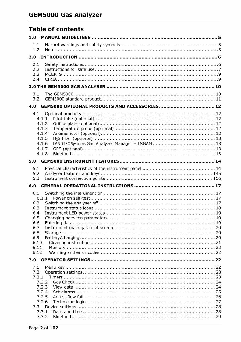
Page 1 of 102 GEM5000 Gas Analyzer Operating Manual QED Environmental Systems, Inc. 2355 Bishop Circle West Dexter, MI. 48130 Tel: (800) 624-2026 Fax :(734) 995-1170 Email: [email protected] Website: www.landtecna.com Rev.2.1.2018
Transcript of Gas Analyser Operating Manual - landtecna.com · GEM5000 Gas Analyzer Page 5 of 102 1.0 Manual...
Page 1 of 102
GEM5000 Gas Analyzer
Operating Manual
QED Environmental Systems, Inc. 2355 Bishop Circle West
Dexter, MI. 48130
Tel: (800) 624-2026 Fax :(734) 995-1170
Email: [email protected] Website: www.landtecna.com
Rev.2.1.2018
GEM5000 Gas Analyzer
Page 2 of 102
Table of contents
1.0 MANUAL GUIDELINES ...................................................................................... 5
1.1 Hazard warnings and safety symbols .................................................................. 5 1.2 Notes ............................................................................................................ 5
2.0 INTRODUCTION ............................................................................................... 6
2.1 Safety instructions........................................................................................... 6 2.2 Instructions for safe use ................................................................................... 7 2.3 MCERTS ......................................................................................................... 9 2.4 CIRIA ............................................................................................................ 9
3.0 THE GEM5000 GAS ANALYSER .......................................................................... 10
3.1 The GEM5000 ............................................................................................... 10 3.2 GEM5000 standard product ............................................................................. 11
4.0 GEM5000 OPTIONAL PRODUCTS AND ACCESSORIES ...................................... 12
4.1 Optional products .......................................................................................... 12 4.1.1 Pitot tube (optional) ................................................................................. 12 4.1.2 Orifice plate (optional) .............................................................................. 12 4.1.3 Temperature probe (optional) .................................................................... 12 4.1.4 Anemometer (optional) ............................................................................. 12 4.1.5 H2S filter (optional) .................................................................................. 13 4.1.6 LANDTEC Systems Gas Analyzer Manager – LSGAM .......................................... 13 4.1.7 GPS (optional) ......................................................................................... 13 4.1.8 Bluetooth ................................................................................................ 13
5.0 GEM5000 INSTRUMENT FEATURES ................................................................. 14
5.1 Physical characteristics of the instrument panel ................................................. 14 5.2 Analyser features and keys ........................................................................... 145 5.3 Instrument connection points ........................................................................ 156
6.0 GENERAL OPERATIONAL INSTRUCTIONS ....................................................... 17
6.1 Switching the instrument on ........................................................................... 17 6.1.1 Power on self-test .................................................................................... 17
6.2 Switching the analyser off .............................................................................. 17 6.3 Instrument status icons .................................................................................. 18 6.4 Instrument LED power states .......................................................................... 19 6.5 Changing between parameters ........................................................................ 19 6.6 Entering data ................................................................................................ 19 6.7 Instrument main gas read screen .................................................................... 20 6.8 Storage ....................................................................................................... 20 6.9 Battery/charging ........................................................................................... 20 6.10 Cleaning instructions ................................................................................... 21 6.11 Memory .................................................................................................... 22 6.12 Warning and error codes ............................................................................. 22
7.0 OPERATOR SETTINGS ..................................................................................... 22
7.1 Menu key ..................................................................................................... 22 7.2 Operation settings ......................................................................................... 23 7.2.1 Timers ...................................................................................................... 23
7.2.2 Gas Check .............................................................................................. 24 7.2.3 View data ............................................................................................... 24 7.2.4 Set alarms .............................................................................................. 25 7.2.5 Adjust flow fail ........................................................................................ 26 7.2.6 Technician login ....................................................................................... 27
7.3 Device settings ............................................................................................. 28 7.3.1 Date and time ......................................................................................... 28 7.3.2 Bluetooth ................................................................................................ 29
GEM5000 Gas Analyzer
Page 3 of 102
7.3.3 Device information ................................................................................... 30 7.3.4 Diagnostics ............................................................................................. 30 7.3.5 Navigation (optional) ................................................................................ 31
7.4 User settings ................................................................................................ 32 7.4.1 Operating language .................................................................................. 32 7.4.2 Units of measurement .............................................................................. 33 7.4.3 ID selection ............................................................................................ 34 7.4.4 Routes ................................................................................................. 36 7.4.5 Adjust backlight ....................................................................................... 36 7.4.6 Adjust volume ......................................................................................... 37 7.4.7 User Prompts .......................................................................................... 38
7.5 Exit menu .................................................................................................... 38
8.0 TAKING READINGS ......................................................................................... 39
8.1 Preliminary checks before taking readings (best practice) .................................... 39 8.2 Change screen layout ....................................................................................... 41 8.3 Answering site questions ................................................................................ 41 8.4 Answering ID questions .................................................................................... 41 8.5 Special action ............................................................................................... 42
8.5.1 Configuration of the data logging option ......................................................... 43 8.5.2 Profiling option ........................................................................................... 43
8.6 GEM analyser in GA mode .............................................................................. 44 8.7 The gas flow measurement screen ................................................................... 44 8.8 How to use an anemometer (optional) .............................................................. 45 8.9 How to use a pitot tube (optional) ................................................................... 48 8.10 How to use an H2S filter (optional) ................................................................ 49
8.10.1 Cross gas effects on chemical cells ............................................................. 49 8.10.2 Cross-gas effects on methane, carbon dioxide and oxygen ............................. 50
8.11 How to use a temperature probe (optional) .................................................... 52 8.12 How to identify a borehole using the GPS feature (optional) .............................. 53 8.13 Taking gas and flow measurement ................................................................ 56
9.0 CALIBRATION ................................................................................................ 56
9.1 Calibration introduction .................................................................................. 56 9.2 Frequency of calibration – best practice ............................................................ 57 9.3 Calibration gases ........................................................................................... 58 9.4 Calibration set-up .......................................................................................... 58 9.5 Calibration equipment .................................................................................... 59 9.6 Gas analyzer ................................................................................................ 60 9.7 Calibration processes – best practice ................................................................ 60
9.7.1 Gas Check in fresh air .............................................................................. 61 9.7.2 Calibration – mixtures 1, 2, & 3 ................................................................. 62 9.8 Restore to factory ....................................................................................... 63
9.9 Calibration history ......................................................................................... 63 9.10 Calibration summary ................................................................................... 63
10.0 THE LANDTEC GAS ANALYZER MANAGER SOFTWARE (LSGAM)…………………..64
10.1 LANDTEC System Online Users……………………………………………………………………………………64 10.2 Offline Users………………………………………………………………………………………………………………….64
10.3 Installation with CD or Memory Stick………………………………………………………………………….65 10.4 Start Up………………………………………………………………………………………………………………………..66
10.5 Navigation…………………………………………………………………………………………………………………….67
10.6 Connecting to the Instrument……………………………………………………………………………………..68 10.7 Create a Project/Select a Project…………………………………………………………………………………69
10.7.1 ID Setup………………………………………………………………………………………………………………..70 10.7.2 Creating Comments………………………………………………………………………………………………70
10.7.3 Creating ID's…………………………………………………………………………………………………………71 10.7.4 Importing Data Field CS ID's……………………………………………………………………………….75
10.7.5 Create a New Project (ID's already in the instrument)……………………………………….75 10.7.6 Creating Site Questions………………………………………………………………………………76
GEM5000 Gas Analyzer
Page 4 of 102
10.7.7 Working with Device ID's……………………………………………………………………………..78 10.7.8 Sending ID's to the Instrument……………………………………………………………………….80 10.7.9 Clearing ID's or Deleting a Project…………………………………………………………………..82 10.7.10 Clearing the Instrument Memory…………………………………………………………………….84 10.7.11 Instrument Settings……………………………………………………………………………………85 10.7.12 Alarm Settings…………………………………………………………………………………………86 10.7.13 Misc. Options…………………………………………………………………………………………..87 10.7.14 Units of Measurement………………………………………………………………………… ……88 10.7.15 Downloading Readings……………………………………………………………………………….91 10.7.16 Clear Readings………………………………………………………………………………………...93 10.7.17 Exporting Readings……………………………………………………………………………………94
11.0 PROBLEM SOLVING ..................................................................................... 95
12.0 WARNING AND ERROR DISPLAY.................................................................. 95
13.0 SERVICE ...................................................................................................... 96
14.0 WARRANTY POLICY ..................................................................................... 97
15.0 GLOSSARY OF TERMS .................................................................................. 98
GEM5000 Gas Analyzer
Page 5 of 102
1.0 Manual guidelines
1.1 Hazard warnings and safety symbols
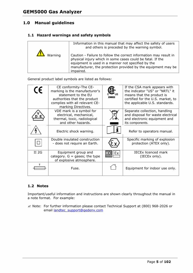
Warning
Information in this manual that may affect the safety of users and others is preceded by the warning symbol.
Caution - Failure to follow the correct information may result in
physical injury which in some cases could be fatal. If the equipment is used in a manner not specified by the
manufacturer, the protection provided by the equipment may be
impaired.
General product label symbols are listed as follows:
CE conformity-The CE-
marking is the manufacturer's
statement to the EU authorities that the product
complies with all relevant CE-marking Directives.
If the CSA mark appears with
the indicator "US" or "NRTL" it
means that the product is certified for the U.S. market, to
the applicable U.S. standards.
VDE mark is a symbol for
electrical, mechanical, thermal, toxic, radiological
and other hazards.
Separate collection, handling
and disposal for waste electrical and electronic equipment and its components.
Electric shock warning.
Refer to operators manual.
Double insulated construction - does not require an Earth.
Specific marking of explosion protection (ATEX only).
II 2G Equipment group and category. G = gases; the type
of explosive atmosphere.
IECEx licenced mark (IECEx only).
Fuse.
Equipment for indoor use only.
1.2 Notes Important/useful information and instructions are shown clearly throughout the manual in
a note format. For example:
Note: For further information please contact Technical Support at (800) 968-2026 or
email [email protected]
GEM5000 Gas Analyzer
Page 6 of 102
2.0 Introduction This manual explains how to use the GEM5000 landfill gas analyzer. The GEM5000 has
additional functionality to the GA5000 gas analyzer. The GA5000 measures gas
concentrations only, whereas the GEM5000 measures flow and gas concentrations. The GEM5000 measures flow and calculates the calorific values of the gas as well as being a
useful tool for balancing the gas field. The GEM5000 gas analyzer may be used to monitor, calculate, adjust and record the flow at each monitoring point.
This instrument may also be used in GA5000 mode of operation if required. The operator
may change the analyzer between a gas extraction monitor (a GEM5000 gas analyzer) or a landfill gas analyzer (a GA5000 gas analyzer). The mode of operation can be changed from
the ‘Special Action’ menu. Please refer to section ‘8.0 – Taking Readings’ for further
instruction.
The 5000 series of gas analyzers complies with Part 15 of the FCC Rules. Operation is subject to the following two conditions:
1) This device may not cause harmful interference.
2) This device must accept any interference received, including interference that may cause
undesired operation.
2.1 Safety instructions
Warning
The 5000 series of gas analyzers can be used for measuring gases from landfill sites and other sources as described in this manual.
The operator may be exposed to harmful gases during the use of the instrument. Inhaling these gases may be harmful to health and in
some cases may be fatal.
It is the responsibility of the user to ensure that he/she is adequately trained in the safety aspects of the gases being used and appropriate
procedures are followed. In particular, where hazardous gases are being used the gas exhausted from the analyzer must be piped to an
area where it is safe to discharge the gas.
Hazardous gas can also be expelled from the instrument when
purging with clean air.
The instrument has been designed to be used in explosive atmospheres as defined by the classification. The instrument can be
configured to measure low levels of several gases, but may not be certified for use in potentially explosive atmospheres of these gases.
It is the responsibility of the operator to determine the protection
concept and classification of equipment required for a particular application and whether these gases create a potentially explosive
atmosphere.
Note: Gas analyzers are a sensitive piece of scientific equipment, and should be
treated as such. If the equipment is used in a manner not specified by the
manufacturer, the protection provided by the instrument may be impaired.

GEM5000 Gas Analyzer
Page 7 of 102
2.2 Instructions for safe use
For ATEX and IECEx the 5000 series of gas analysers are certified to Hazardous Area Classification
II 2G Ex ib IIA T1 Gb (Ta = -10ºC to +50ºC)
It is vital instructions are followed closely. It is the responsibility of the operator to determine the protection concept and classification required for a particular application.
(Reference European ATEX directive 2014/34/EU)
The following instructions apply to equipment covered by certificate numbers SIRA 11ATEX2197X and IECEx SIR 11.0089X:
The equipment may be used with flammable gases and vapours with apparatus group IIA and temperature class T1.
The equipment can contain gas sensing heads for the detection of particular gases.
The inclusion of a sensor does not infer that the equipment is suitable for the use of gases with a temperature class of less than T1.
The equipment is only certified for use in ambient temperatures in the range -10ºC to +50ºC and should not be used outside this range.
The equipment must not be used in an atmosphere of greater than 21% oxygen.
Repair of this equipment shall be carried out in accordance with the applicable code
of practice.
When used in a hazardous area only use GF5.2 temperature probe (SIRA
11ATEX2197X and IECEx SIR11.0089X). For connector C, the GF5.4 anemometer
(BVS 04ATEXE194) for use with ATEX only. The analyser should not be connected to any other devices in the hazardous area including the GF-USB lead (connector A)
or GF3.9 battery charger (connector B) supplied with the analyzer.
Do not charge, recharge or open in a potentially explosive atmosphere. In hazardous area only use “Temperature Probe GF5.2” in Connector B.
Connector C (Uo=10V,lo=5mA,Po=50mW,Ci=0,Li=0,Co=100uF,Lo=1000mH), Connector B (Uo=5V,lo=6mA,Po=7mW,Ci=0,Li=0,Co=100uF,Lo=1000mH)
MAXIMUM NON-HAZARDOUS SUPPLIES: Connector A - Um=6V Connector B - Um=10.1V
The safe area apparatus that is to be connected to the USB Port shall be a Safety
Extra Low Voltage (SELV) or Protective Extra Low Voltage (PELV) circuit.
Only a Geotechnical Instrument battery pack part number 20087 or 2011113 is
permitted as a replacement. This battery pack is not field replaceable and shall only be changed in a safe area by QED personnel.
Only Battery Charger type GF3.9 shall be used to recharge the batteries via
Connector ‘B’.
If the equipment is likely to come into contact with aggressive substances, e.g.
acidic liquids or gases that may attack metals, or solvents that may affect polymeric materials, then it is the responsibility of the user to take suitable
precautions, e.g. regular checks as part of routine inspections or establishing from the material’s data sheet that it is resistant to specific chemicals that prevent it
GEM5000 Gas Analyzer
Page 8 of 102
from being adversely affected, thus ensuring that the type of protection is not
compromised.
The relative pressure range is +/-500 mbar. Note, however, that the input pressure
should not exceed +/- 500 mbar relative to atmospheric pressure and the output pressure should not exceed +/- 100 mbar relative to atmospheric pressure.
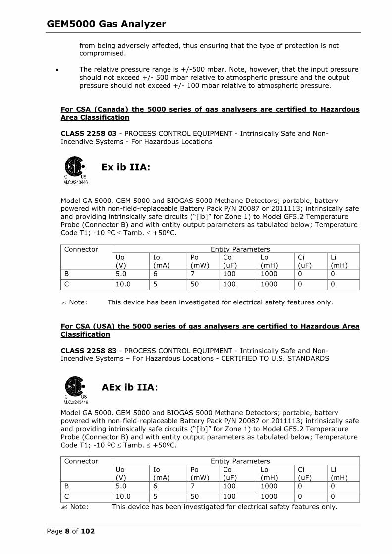
For CSA (Canada) the 5000 series of gas analysers are certified to Hazardous Area Classification
CLASS 2258 03 - PROCESS CONTROL EQUIPMENT - Intrinsically Safe and Non-
Incendive Systems - For Hazardous Locations
Ex ib IIA:
Model GA 5000, GEM 5000 and BIOGAS 5000 Methane Detectors; portable, battery powered with non-field-replaceable Battery Pack P/N 20087 or 2011113; intrinsically safe
and providing intrinsically safe circuits (“[ib]” for Zone 1) to Model GF5.2 Temperature
Probe (Connector B) and with entity output parameters as tabulated below; Temperature
Code T1; -10 ºC Tamb. +50ºC.
Connector Entity Parameters
Uo
(V)
Io
(mA)
Po
(mW)
Co
(uF)
Lo
(mH)
Ci
(uF)
Li
(mH)
B 5.0 6 7 100 1000 0 0
C 10.0 5 50 100 1000 0 0
Note: This device has been investigated for electrical safety features only.
For CSA (USA) the 5000 series of gas analysers are certified to Hazardous Area
Classification
CLASS 2258 83 - PROCESS CONTROL EQUIPMENT - Intrinsically Safe and Non-
Incendive Systems – For Hazardous Locations - CERTIFIED TO U.S. STANDARDS
AEx ib IIA:
Model GA 5000, GEM 5000 and BIOGAS 5000 Methane Detectors; portable, battery powered with non-field-replaceable Battery Pack P/N 20087 or 2011113; intrinsically safe
and providing intrinsically safe circuits (“[ib]” for Zone 1) to Model GF5.2 Temperature Probe (Connector B) and with entity output parameters as tabulated below; Temperature
Code T1; -10 ºC Tamb. +50ºC.
Connector Entity Parameters
Uo (V)
Io (mA)
Po (mW)
Co (uF)
Lo (mH)
Ci (uF)
Li (mH)
B 5.0 6 7 100 1000 0 0
C 10.0 5 50 100 1000 0 0
Note: This device has been investigated for electrical safety features only.

GEM5000 Gas Analyzer
Page 9 of 102
2.3 MCERTS
MCERTS is the UK Environment Agency's Monitoring Certification Scheme. The scheme provides a framework within which environmental measurements can be made in
accordance with the Agency's quality requirements. The scheme covers a range of monitoring, sampling and inspection activities.
MCERTS promotes public confidence in monitoring data and provides industry with a
proven framework for choosing monitoring systems and services that meet the
Environment Agency's performance requirements.
The Environment Agency has established its Monitoring Certification Scheme (MCERTS) to deliver quality environmental measurements. The MCERTS product certification scheme
provides for the certification of products according to Environment Agency performance standards, based on relevant CEN, ISO and national standards.
MCERTS certified instruments have been tested by an independent body to ensure that
they meet certain performance requirements. In addition the manufacturer of an MCERTS
product is regularly audited to ensure that the performance requirements of the certification are being continually met.
The 5000 series of gas analyzers have been certified to Version 3.1 of the ‘Performance
Standards for Portable Emission Monitoring Systems’.
2.4 CIRIA
The CIRIA guideline ‘Assessing the risks posed by hazardous ground gases to buildings’
proposes that gas concentrations and flow rates should be monitored.
As an example methodology, they suggest using a gas analyser to first measure flow and pressure and then afterwards to measure gas concentration.
The logging profile option offers frequency of data to be collected within a timed period
which, in return, identifies a gas profile of the sample point being monitored, information about whether the sample point is performing correctly, when the peaks occur and
whether air is drawn in after a certain period. This logging option is available on firmware
software version 1.6.5 Versions of the GA5000 analyzer range with internal flow on firmware version 1.6.5 and
above have the ability to take measurements according to the CIRIA guidelines, while still allowing other users to take the measurements as before.

GEM5000 Gas Analyzer
Page 10 of 102
3.0 The GEM5000 Gas Analyzer
3.1 The GEM5000
The GEM5000 gas analyzer is designed to monitor landfill gas extraction systems.
Benefits:
Allows balancing of gas extraction site. Maximize power generation from site.
Field proven. Standardizes monitoring routines.
Easy transfer of data.
GPS for compliance.
Features:
ATEX certified. MCERTS certified.
H2 compensated CO. Calculates flow (m3/hr) and calorific value (kW or BTU).
Technician log-in.
Event log. Two instruments in one (GA and GEM mode).
Measures static and differential pressure. Simultaneous display of gases.
Storage of changes in set-up of gas field. Data logging.
Applications:
Gas extraction fields.
Flare monitoring. Landfill sites.
GEM5000 Gas Analyzer
Page 11 of 102
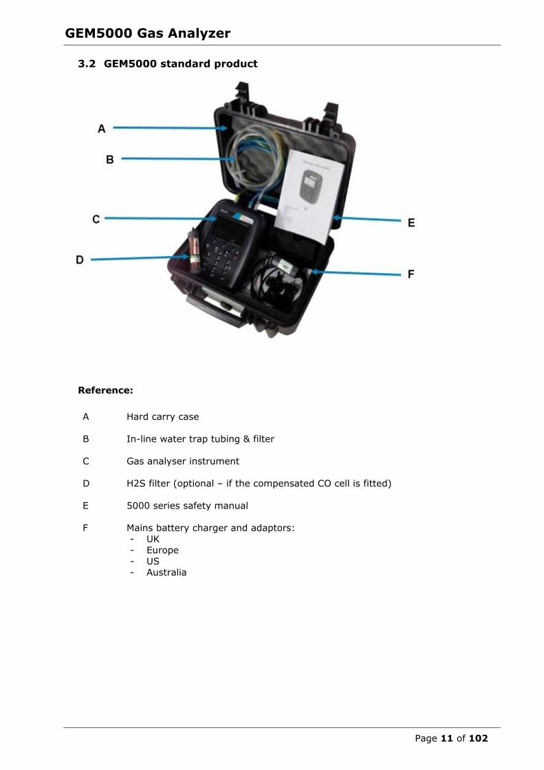
3.2 GEM5000 standard product
Reference:
A Hard carry case
B In-line water trap tubing & filter
C Gas analyser instrument
D H2S filter (optional – if the compensated CO cell is fitted)
E 5000 series safety manual
F Mains battery charger and adaptors:
- UK - Europe
- US - Australia
GEM5000 Gas Analyzer
Page 12 of 102
4.0 GEM5000 Optional Products and Accessories
4.1 Optional products The GEM5000 gas analyzer has a number of optional products for purchase which enhance the usability and enable further analysis of data and reading information.
Note: For more information on the features listed in this section please contact Sales at
(800) 624-2026 or email [email protected]
4.1.1 Pitot tube (optional)
The GEM5000 gas analyzer enables the use of a pitot tube to aid accurate flow measurement. The pitot tube is used for gas extraction systems and the pressure
readings are taken in mbar. High gas flow is calculated in the analyzer in m3/hr (metres cubed per hour).
4.1.2 Orifice plate (optional)
QED recommends the use of orifice plates as good practice when using the GEM5000 gas analyzer, enabling repeatability in flow measurement via a fixed method. Contact Sales
at (800) 624-2026 or email [email protected] if the use of Orifice plates is required.
4.1.3 Temperature probe (optional)
The GEM5000 gas analyzer has the facility to automatically display and record the borehole temperature via an optional temperature probe.
When a temperature probe is fitted the temperature reading will be displayed on the
‘Main Gas Read Screen’ and recorded with all other data.
Note: Temperature probes with an Ex label are part of the GEM5000 Ex certification
SIRA 11ATEX2197X and IECEx SIR11.0089X, and therefore certified for use under the same conditions as the analyzer.
4.1.4 Anemometer (optional)
The GEM5000 gas analyzer has the facility to automatically display and record high flow via an optional anemometer probe. It is designed to plug into the instrument and
instantly provide a flow indication. An anemometer probe adds flow measurements to the professional reporting ability of the GEM5000 range along with gas concentrations,
pressure and temperature.
The anemometer has a simple connection, a narrow diameter measurement head (11mm), a wide temperature operating range (up to 80oC) and indicates flows up to 40
m/sec.
When an anemometer probe is fitted to the analyzer the flow will be displayed in the
‘Main Gas Read Screen’ and recorded with all other data.
Flow can be measured in either m/s (gas velocity) or m3/hr (volume flow rate). In order to calculate the volume flow rate the pipe diameter will need to be entered into the
instrument, either manually or via the Landtec Systems Gas Analyser Manager, (LSGAM), software.
Note: The anemometer probe is ATEX certified for use in a potentially explosive
atmosphere under Ex certificate BVS 04ATEXE194.
GEM5000 Gas Analyzer
Page 13 of 102
4.1.5 H2S filter (optional)
The GEM5000 gas analyzer has the capability to use an H2S filter and is required as standard if the compensated CO cell is fitted and configured at the time the instrument is
manufactured. H2S gas can have a cross-gas effect on the CO reading. By using a filter,
the H2S is removed from the gas sample, therefore providing a more accurate CO reading.
The filter only needs to be used when you are trying to get rid of any possible cross gas
effects H2S might have on other gases. Do not use the filter on all boreholes.
4.1.6 Landtec Systems Gas Analyzer Manager – LSGAM
Landtec Systems Gas Analyzer Manager (LSGAM) enables the operator to maximize the
operation of the gas analyzer. It enables direct communication with the unit, features a
simple upload and download facility and is fully compatible with the latest Microsoft™ operating systems.
Features:
Organization and transfer of borehole IDs and readings to and from the gas
analyzer.
Configuration of the gas analyzer.
Flexible grouping of the IDs.
Structured organization of transferred data.
Automatic detection of instrument type and available options.
Secure data mode to prevent tampering.
First time set-up wizard.
Enable flow measurements for GEM5000 gas analyzers.
4.1.7 GPS (optional)
An optional GPS feature is available for the GEM5000 gas analyzer. It enables the site engineer to automatically locate borehole IDs using GPS satellite signal from predefined
borehole IDs uploaded from LSGAM or set on the analyzer when out in the field prior to
taking a reading. The GPS reading data is stored for each measurement reading providing an audit trail confirming that a reading was taken.
4.1.8 Bluetooth
The analyzers are fitted with a Bluetooth receiver which enables the operator to download readings and upload IDs without the need to connect the analyzer to a PC via a
USB cable.

GEM5000 Gas Analyzer
Page 14 of 102
5.0 GEM5000 Instrument Features
5.1 Physical characteristics of the instrument panel
Front view: Reference:
Back view: Reference:
A Main Gas Read Screen
B Soft-keys
C Backlight Key
D Menu Key
E Pump key
F LED Light
G On/Off Key
H
I
Assistance key
Enter Key
J Scroll up key
K Scroll down key
L Key 0 – Space key
M Model Number
N Serial number
O Part number
P Certificate number
Q Recalibrated date
J
A
B
C
D
E
F
G
H
I
K
L
GEM5000 Gas Analyzer
Page 15 of 102
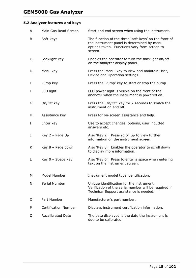
5.2 Analyzer features and keys
A Main Gas Read Screen
Start and end screen when using the instrument.
B Soft-keys
The function of the three ‘soft-keys’ on the front of the instrument panel is determined by menu
options taken. Functions vary from screen to
screen.
C Backlight key Enables the operator to turn the backlight on/off on the analyzer display panel.
D Menu key Press the ‘Menu’ key to view and maintain User,
Device and Operation settings.
E Pump key Press the ‘Pump’ key to start or stop the pump.
F LED light
LED power light is visible on the front of the
analyzer when the instrument is powered on.
G On/Off key
Press the ‘On/Off’ key for 2 seconds to switch the instrument on and off.
H
Assistance key
Press for on-screen assistance and help.
I Enter key Use to accept changes, options, user inputted answers etc.
J Key 2 – Page Up Also ‘Key 2’. Press scroll up to view further
information on the instrument screen.
K Key 8 – Page down Also ‘Key 8’. Enables the operator to scroll down to display more information.
L Key 0 – Space key
Also ‘Key 0’. Press to enter a space when entering text on the instrument screen.
M Model Number Instrument model type identification.
N
Serial Number
Unique identification for the instrument. Verification of the serial number will be required if
Technical Support assistance is needed.
O
Part Number
Manufacturer’s part number.
P
Certification Number
Displays instrument certification information.
Q
Recalibrated Date The date displayed is the date the instrument is
due to be calibrated.
GEM5000 Gas Analyzer
Page 16 of 102
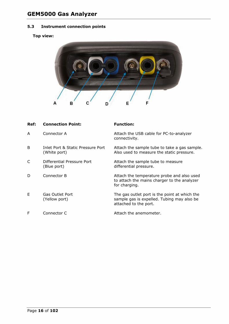
5.3 Instrument connection points
Top view:
Ref: Connection Point: Function:
A Connector A Attach the USB cable for PC-to-analyzer connectivity.
B Inlet Port & Static Pressure Port
(White port)
Attach the sample tube to take a gas sample.
Also used to measure the static pressure.
C Differential Pressure Port
(Blue port)
Attach the sample tube to measure
differential pressure.
D Connector B
Attach the temperature probe and also used to attach the mains charger to the analyzer
for charging.
E Gas Outlet Port
(Yellow port)
The gas outlet port is the point at which the
sample gas is expelled. Tubing may also be attached to the port.
F
Connector C Attach the anemometer.

GEM5000 Gas Analyzer
Page 17 of 102
6.0 General Operational Instructions
6.1 Switching the instrument on 1) To switch on the analyzer, press and hold the ‘On/Off’ key. The Landtec logo will
display followed by the instrument warm up.
2) Following the instrument warm up, the ‘Date and Time’ screen is displayed
prompting the technician to set the date and time and required format.
3) When complete, select the soft-key to ‘Exit’ and the ‘Power On Self-test’ screen is
displayed followed by instrument status. Instrument status displays the instruments service due date, serial number, options, service scheme and software version. Text
will also display stating ‘Self-test complete’.
4) Select the soft-key ‘Next’ to move onto the next screen and the ‘Technician Login’ screen is displayed.
5) Use the cursor keys to move through the list of ID’s. Select either the required ‘Technician ID’ from the list followed by the soft-key ‘Accept’, or select ‘Default’’
followed by the soft-key ‘Accept’ to continue to the ‘Main Gas Read Screen’.
Note: The selected technician ID is displayed at the top left corner of the Main Gas Read Screen.
6.1.1 Power on self-test
When switched on, the read-out will perform a pre-determined self-test sequence. During
this time many of the analyzer’s functions are tested, including:
General operation Gas flow measurement
Calibration Battery charge level
During the self-test the following information is also displayed:
Manufacturer’s service due date The last gas check date
Software version programmed Date format
Serial number Operating language
The currently enabled sales option
Note: The self-test should only be done with the analyzer sampling fresh air.
6.2 Switching the instrument off 1) To switch off the analyzer, press and hold the ‘On/Off’ key, at which point a clean air
purge will be carried out and the instrument will then switch off.
2) If for any reason the analyzer ‘locks up’ and will not switch off in this manner, press
and hold the ‘On/Off’ key for 15 seconds; this will force the instrument to switch off.

GEM5000 Gas Analyzer
Page 18 of 102
6.3 Instrument status icons The following icons may be displayed on the instrument screen:
Icon Description
Icon Description
Battery charge state
Gives the operator an estimation of the battery
charge state. For example 100% gives about 8 hours
use in the field and 50%
would mean that there is approximately 4 hours
battery life remaining.
Battery charge state
Indicates less than 2 hours of charge remaining.
Pump status
This icon is displayed along with a counter
showing the pump run-time. This counts down
where the operator has
specified the pump run-time; if not it counts up;
the icon turns red when stalled.
Pump stalled
This icon is displayed when the pump stalls. The instrument’s gas inlet (or
outlet) may be blocked. This warning is most commonly caused by a water-
logged or dirty sample filter. Change the
sample filter and check for obvious blockages in the sample tubes.
Alternatively, a small amount of adjustment can be made to the low flow
detection point to compensate for minor changes in the performance of the pump
fitted to the instrument.
GPS signal strength This icon shows the signal
strength the analyzer’s GPS module is able to
provide. Full, okay and fair strength respectively.
GPS failure The GPS was unable to get a line of sight
lock on enough satellites. Or, it may be that it hasn’t had time to get a lock.
This indicates when Bluetooth has been
enabled. The color
changes from gray to blue when connected.
Language This icon indicates the currently selected
operating language. This can be changed
via the main menu.
Data logging
This icon indicates that the data logging feature is in
operation.
Service overdue
This icon indicates that the analyzer is overdue for service
Legacy mode This icon indicates that the
analyzer is in legacy mode
and hence is ready to connect to a PC.
USB disabled This icon indicates that the analyzer has
reached a battery critical state, and
hence has turned off its USB connectivity.

GEM5000 Gas Analyzer
Page 19 of 102
6.4 Instrument LED power states When the instrument is powered on a LED power light is visible on the front of the
analyzer, located above the ‘On/Off’ key. The following LED power light states are as follows:
Steady yellow Unit turning on. This will extinguish when software has loaded
correctly.
Flashing (rapid) Unit is powering off.
Flashing (slow) Power off is being delayed for purge/shutdown handling.
Flashing yellow Unit is turning off due to power button being pressed.
Flashing red Unit is turning off due to critically low battery.
Note: Pressing and holding the power button for ~20s resets the analyser.
6.5 Changing between parameters By default, the instrument displays the ‘Main Gas Read Screen’ (for gas measurement).
The instrument will return to this screen after power on or when returning from the menus. The ‘Scroll’ keys can be used to switch to another measurement screen.
6.6 Entering data During normal operation the operator may be prompted to enter data or information via
the keypad, i.e. entering an ID code or setting an alarm level.
When entering data into the instrument all fields are fixed format and are populated from
the left.
Text: Entering text uses similar multi-tap functionality as a mobile phone. Key the
numeric/alpha key pad the required number of times to select the appropriate letter. To key numeric data continue to press the numeric/alpha key until the required number is
displayed.
Numeric data: To enter a new date 09/15/116 the operator would type in 091516 using the numeric
keypad in the following sequence:-
* 0_/__/__ * 09/__/__
* 09/1_/__
* 09/15/__ * 09/15/1_
* 09/15/16
Press the ‘Enter’ key to confirm/accept data keyed.
Any mistakes can be corrected using the soft-key ‘Delete’ which will delete the last digit typed. Alternatively, the sequence can be retyped before the ‘Enter’ key is pressed and
the existing numbers will be pushed off the screen.
Note: The instrument will not allow invalid data to be entered; this should be deleted
and re-entered.
GEM5000 Gas Analyzer
Page 20 of 102
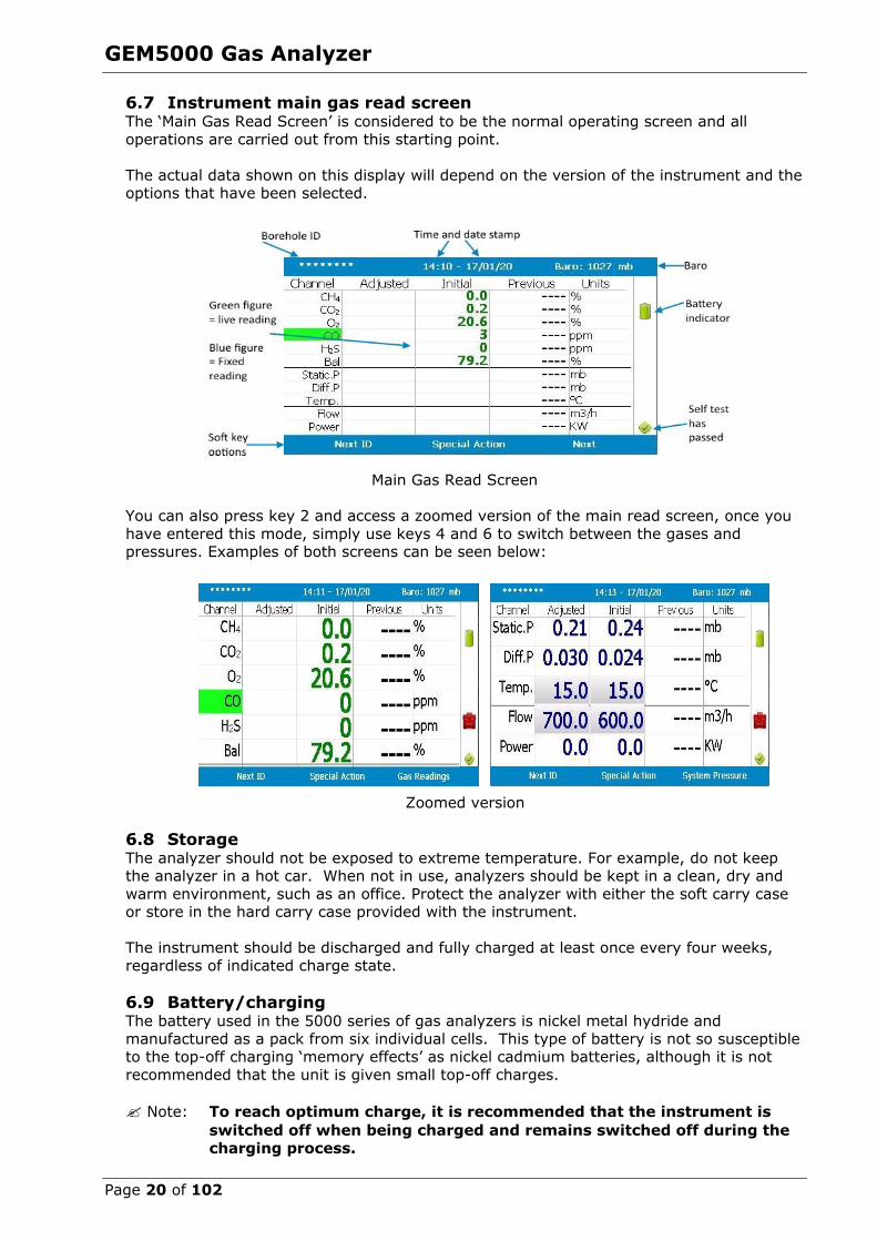
6.7 Instrument main gas read screen The ‘Main Gas Read Screen’ is considered to be the normal operating screen and all
operations are carried out from this starting point.
The actual data shown on this display will depend on the version of the instrument and the options that have been selected.
Main Gas Read Screen
You can also press key 2 and access a zoomed version of the main read screen, once you
have entered this mode, simply use keys 4 and 6 to switch between the gases and pressures. Examples of both screens can be seen below:
Zoomed version
6.8 Storage The analyzer should not be exposed to extreme temperature. For example, do not keep the analyzer in a hot car. When not in use, analyzers should be kept in a clean, dry and
warm environment, such as an office. Protect the analyzer with either the soft carry case or store in the hard carry case provided with the instrument.
The instrument should be discharged and fully charged at least once every four weeks,
regardless of indicated charge state.
6.9 Battery/charging The battery used in the 5000 series of gas analyzers is nickel metal hydride and
manufactured as a pack from six individual cells. This type of battery is not so susceptible to the top-off charging ‘memory effects’ as nickel cadmium batteries, although it is not
recommended that the unit is given small top-off charges.
Note: To reach optimum charge, it is recommended that the instrument is
switched off when being charged and remains switched off during the
charging process.

GEM5000 Gas Analyzer
Page 21 of 102
A full charge will take approximately 4 hours from a fully discharged battery.
Warning The battery charger is NOT covered by the Ex certification.
The battery must be charged only in a safe area.
The battery charger is intelligent and will indicate when the unit is charging and charged.
The instrument must be charged ONLY using the battery charger supplied with the
instrument. The battery charger supplied is intended for indoor use only. Please ensure
adequate ventilation while charging. Typically, a fully charged battery will last 7-8 hours. A quick 30 minute charge can be used to give approximately one hours use in the field but
this may shorten the battery life. Temperature can dramatically affect the battery life; please take this into account when estimating battery life.
Note: Connect the charger to the mains attaching the appropriate adaptor.
Power supply front and back drawing:
Charger: Input voltage: 100-240V AC +/- 10%
Input frequency: 50-60Hz +/- 10% Input current: 0.4A@100VAC .. 0.2A@240VAC
Output voltage: 10.1VDC max
Output current: 1.5A max
Note: This charger has been internally restricted to 1.5A
6.10 Cleaning instructions Do NOT use any cleaning agents to clean the analyzer or battery charger as they may
have an adverse effect on the safe use of these devices.

GEM5000 Gas Analyzer
Page 22 of 102
6.11 Memory The analyzer's memory is stored in a readings and configuration database. The analyzer
will prompt when its memory is full, and you will not be able to store any further readings. Please download your readings via LSGAM or the Basic Download Software and then clear
the memory.
Note: The analyzer should never be stored for prolonged periods with valuable data in
its memory. It is advisable to download all readings to LSGAM at the end of each day’s monitoring. To clear the memory, please refer to the LSGAM
operating manual.
6.12 Warning and error codes When switched on the instrument will perform a predetermined self-test sequence taking approximately ten seconds. During this time many of the instrument’s working parameters
and settings are checked. If any operational parameters are out of specification or if the
pre-programmed recommended calibration/service date has passed, errors or warnings may be displayed.
Note: For further information please refer to section ‘10.0 Problem Solving’.
7.0 Operator Settings
7.1 Menu key
The ‘Menu’ key enables the operator to select options to set up specific parameters and perform operational tasks prior to sample readings being
taken or to view data and information stored in the instrument.
1) Select the ‘Menu’ key on the front of the analyzer and the following screen is displayed:
2) Press the relevant numeric key on the analyzer keypad to select the required option.
3) To exit this menu, select the soft-key ‘Exit’ on the front of the analyzer and the operator is returned to Main Gas Read Screen.

GEM5000 Gas Analyzer
Page 23 of 102
7.2 Operation settings To access the ‘Operation settings’ menu, select the ‘Menu’ key on the front of the analyzer.
The following menu is displayed:
7.2.1 Timers
The timers function enables the operator to set standard purge times and
set auto-power off if the unit is untouched for the period of time specified.
1) Select ‘Key 1 – Timers’ and the following screen is displayed:
1) Select ‘Key 1’ to edit the purge time. Enter the ‘Pump Running Time’ in seconds; this is the length of time you wish to run the pump to draw the sample, e.g. key in
030 then press the ‘Enter’ key to accept.
2) Select ‘Key 2’ to edit the auto power off time. Enter the ‘Auto power off’ in
minutes; the instrument will automatically power off to preserve the battery life after the specified time if no activity has occurred on the instrument. Press the
‘Enter’ key to accept.
3) Select the soft-key ‘Exit’ key to exit the screen and return to the ‘Operation settings’ menu.
Note: Setting the purge time and auto power off functions to zero, disables the
option. It is not recommended to reduce the purge time to below 30 seconds.
GEM5000 Gas Analyzer
Page 24 of 102
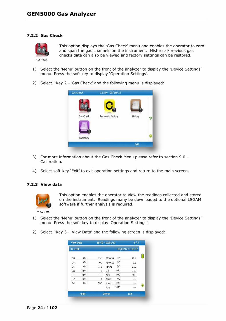
7.2.2 Gas Check
This option displays the ‘Gas Check’ menu and enables the operator to zero
and span the gas channels on the instrument. Historical/previous gas checks data can also be viewed and factory settings can be restored.
1) Select the ‘Menu’ button on the front of the analyzer to display the ‘Device Settings’ menu. Press the soft key to display ‘Operation Settings’.
2) Select ‘Key 2 – Gas Check’ and the following menu is displayed:
3) For more information about the Gas Check Menu please refer to section 9.0 –
Calibration.
4) Select soft-key ‘Exit’ to exit operation settings and return to the main screen.
7.2.3 View data
This option enables the operator to view the readings collected and stored
on the instrument. Readings many be downloaded to the optional LSGAM
software if further analysis is required.
1) Select the ‘Menu’ button on the front of the analyzer to display the ‘Device Settings’
menu. Press the soft-key to display ‘Operation Settings’.
2) Select ‘Key 3 – View Data’ and the following screen is displayed:

GEM5000 Gas Analyzer
Page 25 of 102
3) Toggle through the reading by selecting ‘Key 4 – Scroll left’ and ‘Key 6 – Scroll right’
on the analyzer. Select ‘Key 2 – Page up’ and ‘Key 8 – Page down’ to page through the auxiliary channels listed.
4) Select the soft-key ‘Filter’ to filter the data by sample point ID, or specify before or after date. Press the soft-key ‘Exit’ to exit the filter menu and return to the ‘View
Data’ screen.
5) Select the soft-key ‘Delete’ followed by the appropriate soft-key to delete a single
reading or all filtered readings. Press soft-key ‘Cancel’ to cancel the deletion request.
6) Select the soft-key ‘Exit’ to exit the view data screen.
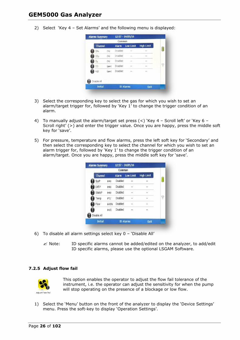
7.2.4 Set alarms
This option enables the operator to define the conditions for which an
alarm/target will be triggered. These conditions apply to the general operation of the instrument and are not ID specific. A summary of the alarm
settings can be found in ‘Key 3 – Summary’.
Types of alarms Common Alarms – Are non-ID specific alarms which apply to all the readings taken
with the analyzer.
ID specific alarms – Are ID specific, i.e. they will only trigger when a certain Id is being used.
Tuning/targets – You can also set targets for your gas channels; these will highlight
gas channels green as oppose to when they alarm (yellow). These can be common or
ID specific.
Setting up alarms/targets 1) Select the ‘Menu’ button on the front of the analyzer to display the ‘Device Settings’
menu. Press the soft key to display ‘Operation Settings’.
GEM5000 Gas Analyzer
Page 26 of 102
2) Select ‘Key 4 – Set Alarms’ and the following menu is displayed:
3) Select the corresponding key to select the gas for which you wish to set an alarm/target trigger for, followed by ‘Key 1’ to change the trigger condition of an
alarm.
4) To manually adjust the alarm/target set press (<) ‘Key 4 – Scroll left’ or ‘Key 6 –
Scroll right’ (>) and enter the trigger value. Once you are happy, press the middle soft key for ‘save’.
5) For pressure, temperature and flow alarms, press the left soft key for ‘Secondary’ and
then select the corresponding key to select the channel for which you wish to set an alarm trigger for, followed by ‘Key 1’ to change the trigger condition of an
alarm/target. Once you are happy, press the middle soft key for ‘save’.
6) To disable all alarm settings select key 0 – ‘Disable All’
Note: ID specific alarms cannot be added/edited on the analyzer, to add/edit
ID specific alarms, please use the optional LSGAM Software.
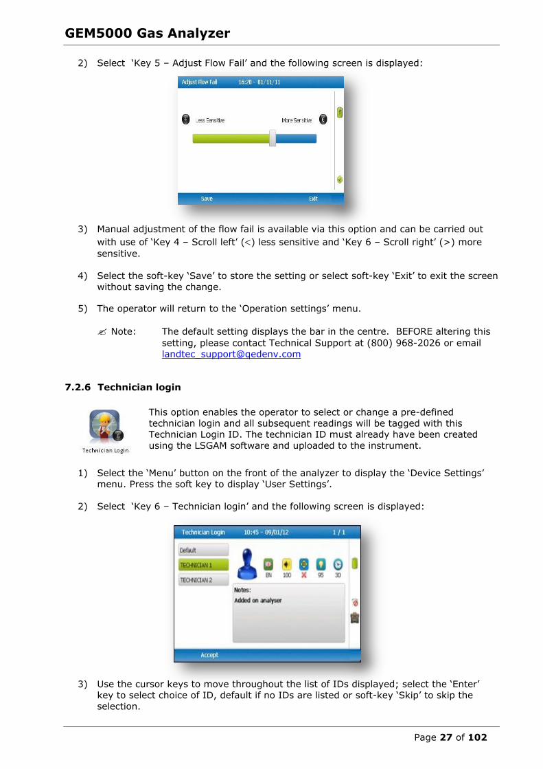
7.2.5 Adjust flow fail
This option enables the operator to adjust the flow fail tolerance of the instrument, i.e. the operator can adjust the sensitivity for when the pump
will stop operating on the presence of a blockage or low flow.
1) Select the ‘Menu’ button on the front of the analyzer to display the ‘Device Settings’
menu. Press the soft-key to display ‘Operation Settings’.
GEM5000 Gas Analyzer
Page 27 of 102
2) Select ‘Key 5 – Adjust Flow Fail’ and the following screen is displayed:
3) Manual adjustment of the flow fail is available via this option and can be carried out
with use of ‘Key 4 – Scroll left’ () less sensitive and ‘Key 6 – Scroll right’ (>) more
sensitive.
4) Select the soft-key ‘Save’ to store the setting or select soft-key ‘Exit’ to exit the screen
without saving the change.
5) The operator will return to the ‘Operation settings’ menu.
Note: The default setting displays the bar in the centre. BEFORE altering this
setting, please contact Technical Support at (800) 968-2026 or email
7.2.6 Technician login
This option enables the operator to select or change a pre-defined
technician login and all subsequent readings will be tagged with this Technician Login ID. The technician ID must already have been created
using the LSGAM software and uploaded to the instrument.
1) Select the ‘Menu’ button on the front of the analyzer to display the ‘Device Settings’
menu. Press the soft key to display ‘User Settings’.
2) Select ‘Key 6 – Technician login’ and the following screen is displayed:
3) Use the cursor keys to move throughout the list of IDs displayed; select the ‘Enter’ key to select choice of ID, default if no IDs are listed or soft-key ‘Skip’ to skip the
selection.

GEM5000 Gas Analyzer
Page 28 of 102
4) The operator will return to the ‘User settings’ menu.
Note: If no technicians are loaded via LSGAM, this section is skipped during
start up and the ‘Technician ID’ icon is removed from the menu.
7.3 Device settings
To access the ‘Device Settings’ menu, select the ‘Menu’ key on the front of the analyzer to
display the ‘Operating Settings’ menu followed by the soft-key to display ‘Device Settings’ menu. The following menu is displayed:
7.3.1 Date and time
This option enables the operator to set the instrument date and time or to receive and update the settings automatically from satellite signal.
1) Select the ‘Menu’ key on the front of the analyzer to display the ‘Device Settings’
menu followed by ‘Key 1 – Date and Time’ and the following screen is displayed:
2) Select ‘Key 1 – Set Date’ and key in the required date. Type the date using the
numeric keypad. Press the soft-key ‘Date Format’ to toggle and select the required
date format i.e. dd/mm/yy. Press the ‘Enter’ key to confirm and update the date setting.
3) Select ‘Key 2 – Set Time’ and key in the required time (hh:mm). Type the time
using the numeric keypad and press the ‘Enter’ key to confirm the update.
GEM5000 Gas Analyzer
Page 29 of 102
4) The operator may also change the default time zone. Selecting the ‘Key 4 Scroll-
left’ or ‘Key 6 – Scroll right’ to move through the different time zones. Press the ‘Enter’ key to confirm your default setting.
5) Select ‘Key 3’ to toggle between ‘Manual Update’ and ‘Automatic Update’ in order to choose how the date and time is set if updating from satellite signal.
Manual
Used to manually obtain and update the date and time from the
satellite signal when requested. Select soft-key ‘Set now’ to set date and time from satellite when available.
Automatic
Used to automatically update the date and time received from the satellite signal when available. This option is only available when
the GPS option is fitted to the analyser at the time of manufacture.
6) Select the soft-key ‘Exit’ to exit and return to the ‘Device Settings’ menu.
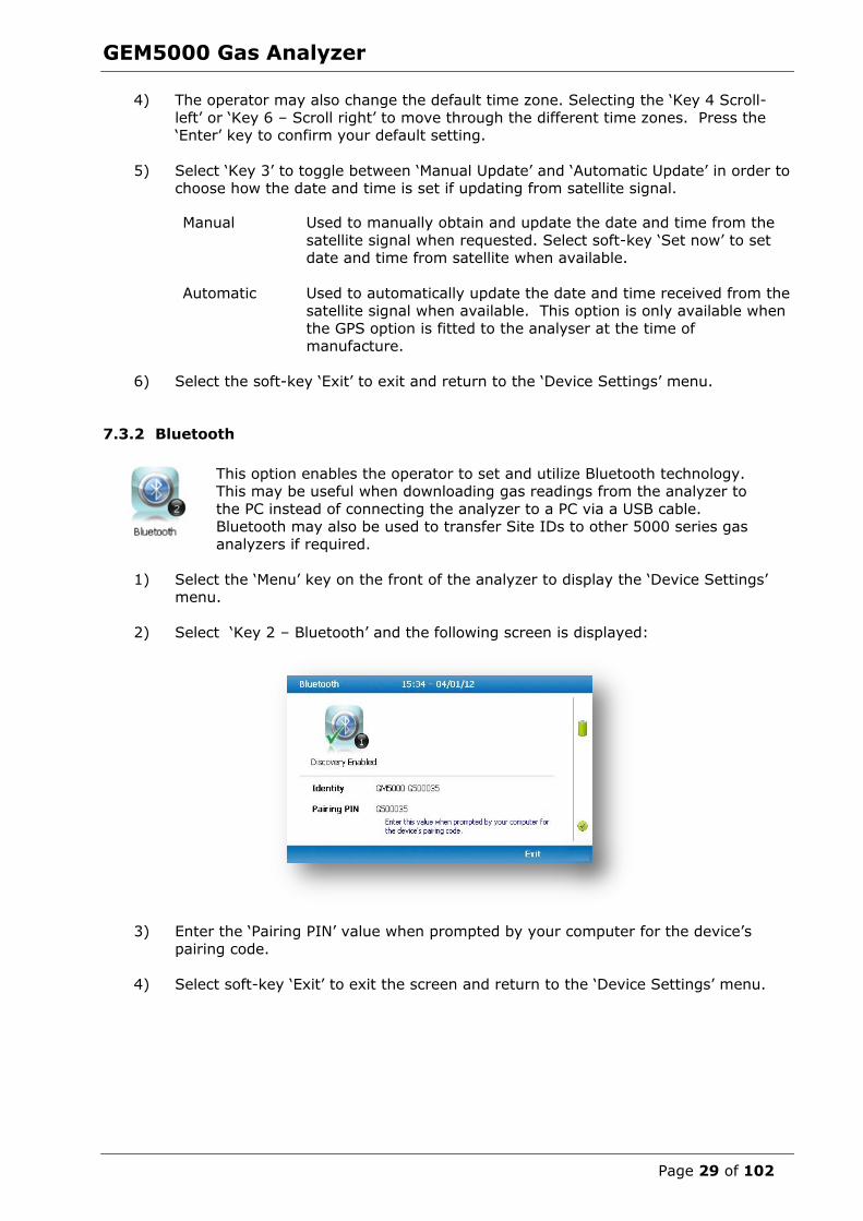
7.3.2 Bluetooth
This option enables the operator to set and utilize Bluetooth technology. This may be useful when downloading gas readings from the analyzer to
the PC instead of connecting the analyzer to a PC via a USB cable. Bluetooth may also be used to transfer Site IDs to other 5000 series gas
analyzers if required.
1) Select the ‘Menu’ key on the front of the analyzer to display the ‘Device Settings’ menu.
2) Select ‘Key 2 – Bluetooth’ and the following screen is displayed:
3) Enter the ‘Pairing PIN’ value when prompted by your computer for the device’s
pairing code.
4) Select soft-key ‘Exit’ to exit the screen and return to the ‘Device Settings’ menu.
GEM5000 Gas Analyzer
Page 30 of 102
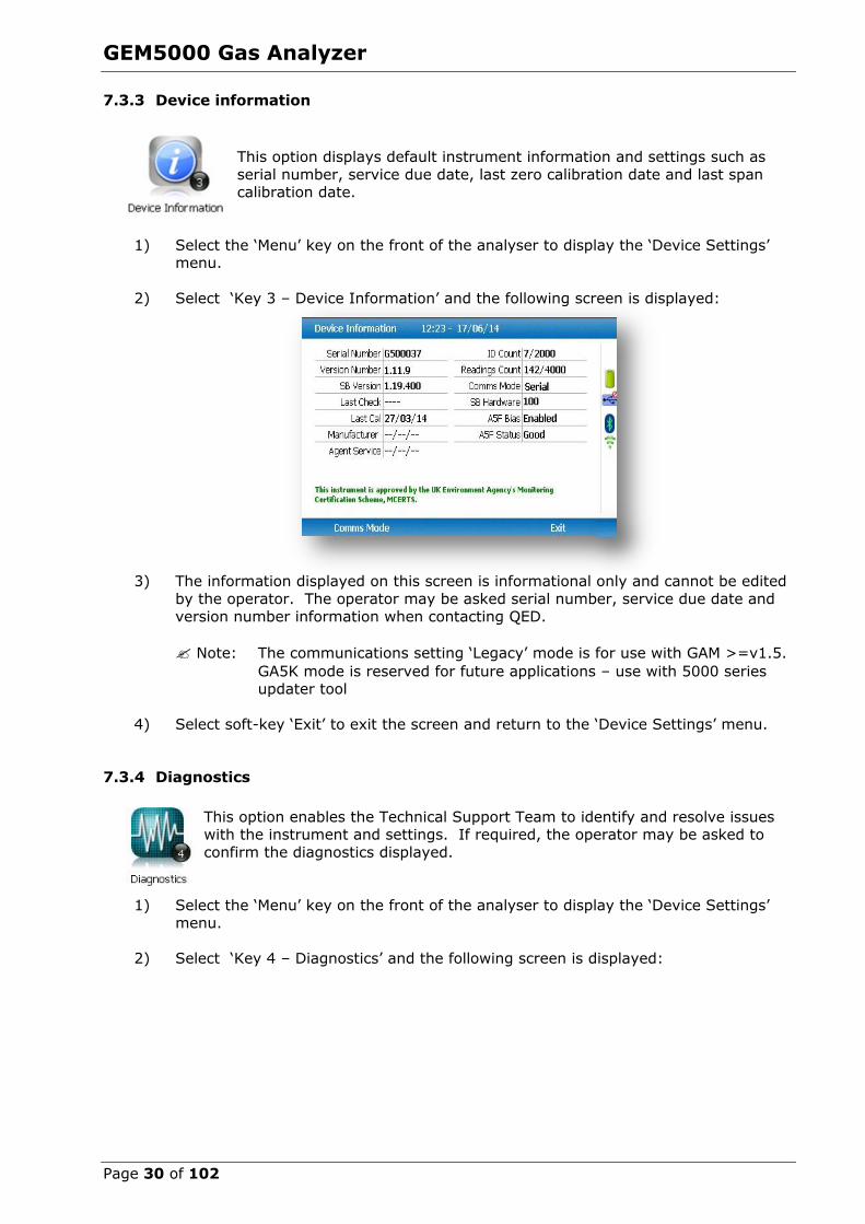
7.3.3 Device information
This option displays default instrument information and settings such as
serial number, service due date, last zero calibration date and last span calibration date.
1) Select the ‘Menu’ key on the front of the analyser to display the ‘Device Settings’ menu.
2) Select ‘Key 3 – Device Information’ and the following screen is displayed:
3) The information displayed on this screen is informational only and cannot be edited
by the operator. The operator may be asked serial number, service due date and
version number information when contacting QED.
Note: The communications setting ‘Legacy’ mode is for use with GAM >=v1.5.
GA5K mode is reserved for future applications – use with 5000 series updater tool
4) Select soft-key ‘Exit’ to exit the screen and return to the ‘Device Settings’ menu.
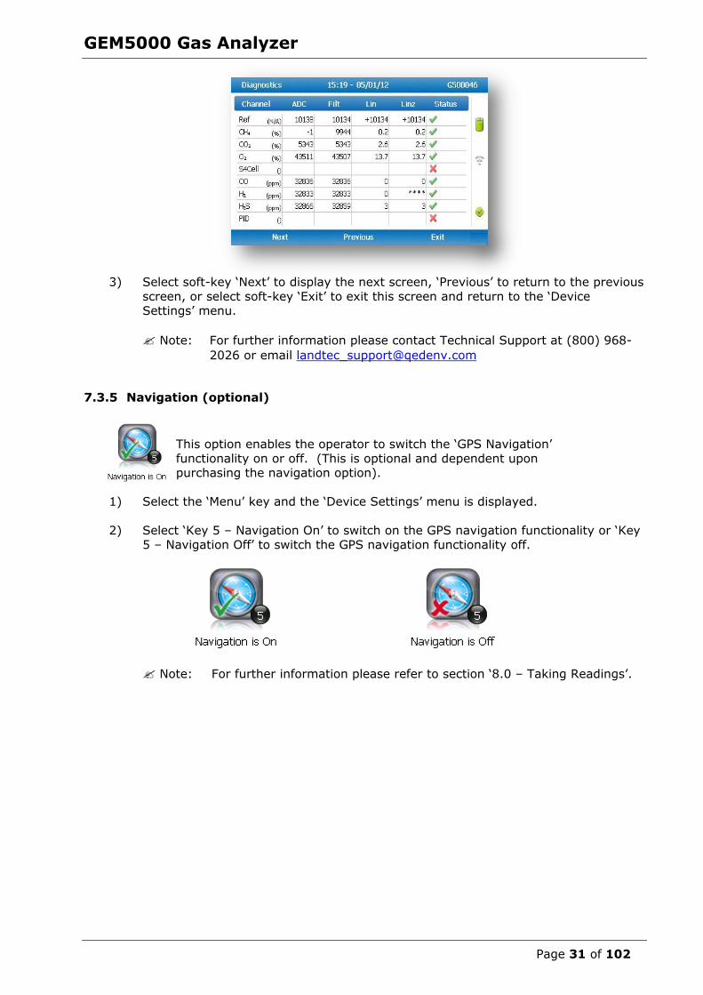
7.3.4 Diagnostics
This option enables the Technical Support Team to identify and resolve issues with the instrument and settings. If required, the operator may be asked to
confirm the diagnostics displayed.
1) Select the ‘Menu’ key on the front of the analyser to display the ‘Device Settings’
menu.
2) Select ‘Key 4 – Diagnostics’ and the following screen is displayed:
GEM5000 Gas Analyzer
Page 31 of 102
3) Select soft-key ‘Next’ to display the next screen, ‘Previous’ to return to the previous
screen, or select soft-key ‘Exit’ to exit this screen and return to the ‘Device Settings’ menu.
Note: For further information please contact Technical Support at (800) 968-
2026 or email [email protected]
7.3.5 Navigation (optional)
This option enables the operator to switch the ‘GPS Navigation’
functionality on or off. (This is optional and dependent upon purchasing the navigation option).
1) Select the ‘Menu’ key and the ‘Device Settings’ menu is displayed.
2) Select ‘Key 5 – Navigation On’ to switch on the GPS navigation functionality or ‘Key 5 – Navigation Off’ to switch the GPS navigation functionality off.
Note: For further information please refer to section ‘8.0 – Taking Readings’.

GEM5000 Gas Analyzer
Page 32 of 102
7.4 User settings
To access the ‘User settings’ menu, select the ‘Menu’ key on the front of the analyzer to display the ‘Operating Settings’ menu followed by the soft-key to display ‘User Settings’
menu. The following menu is displayed:
To exit the user settings menu select the soft-key ‘Exit’.
7.4.1 Operating language
This option enables the operator to specify the operating language
displayed for the instrument.
1) Select ‘Key 1 – Operating Language’ and the following screen is displayed:
GEM5000 Gas Analyzer
Page 33 of 102
Set the required language for the gas analyser by selecting the appropriate function key.
Choose from, on the first page:
Key 1 English
Key 2 Spanish
Key 3 French
Key 4 German
Key 5 Italian
Key 6
Portuguese
Use the soft-keys to move to the next page for further language options, including simplified Chinese
2) To exit this option, select the soft-key ‘Exit’ and the operator is returned to the
‘User Settings’ menu.
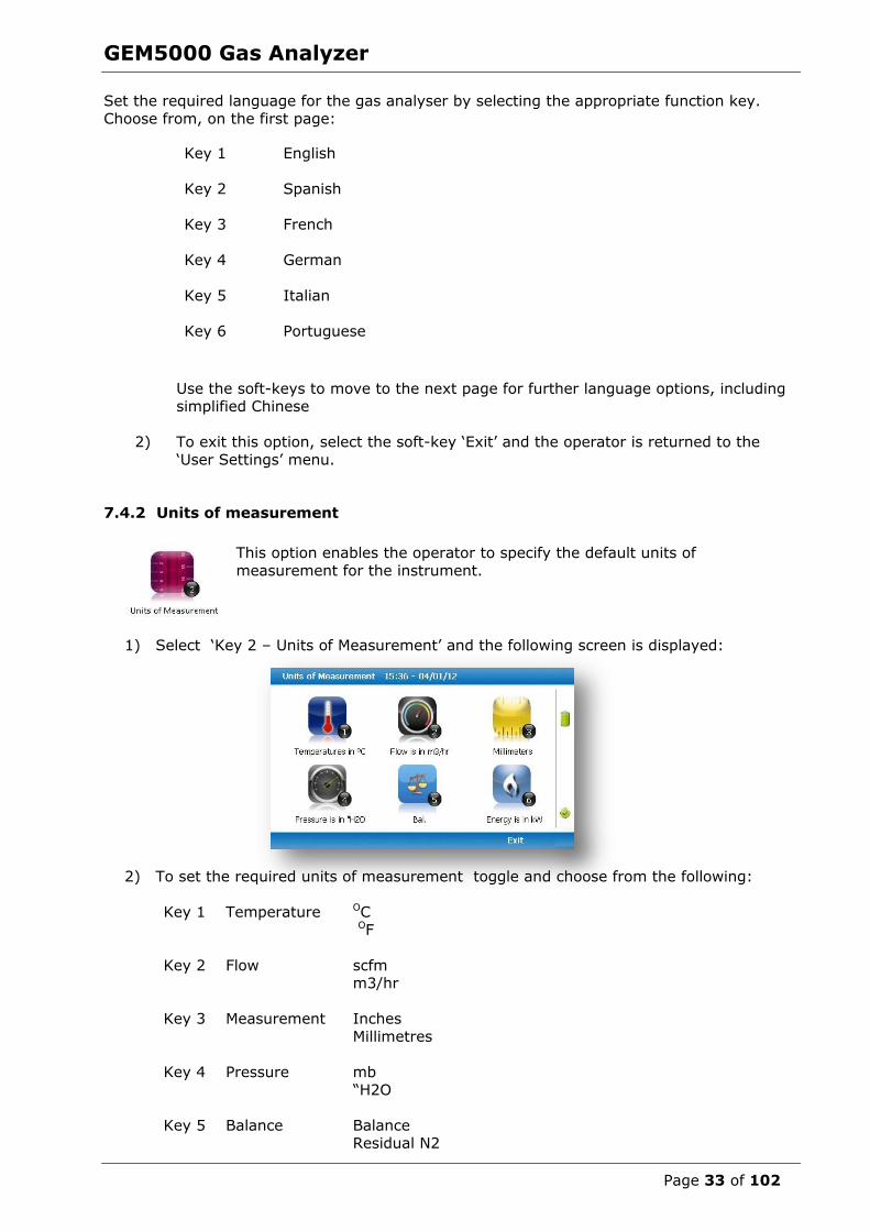
7.4.2 Units of measurement
This option enables the operator to specify the default units of
measurement for the instrument.
1) Select ‘Key 2 – Units of Measurement’ and the following screen is displayed:
2) To set the required units of measurement toggle and choose from the following:
Key 1
Temperature OC
OF
Key 2
Flow scfm m3/hr
Key 3
Measurement Inches
Millimetres
Key 4
Pressure mb
“H2O
Key 5
Balance Balance Residual N2
GEM5000 Gas Analyzer
Page 34 of 102
3) Select soft-key ‘Exit’ to exit this screen and return to the ‘User Settings’ menu.
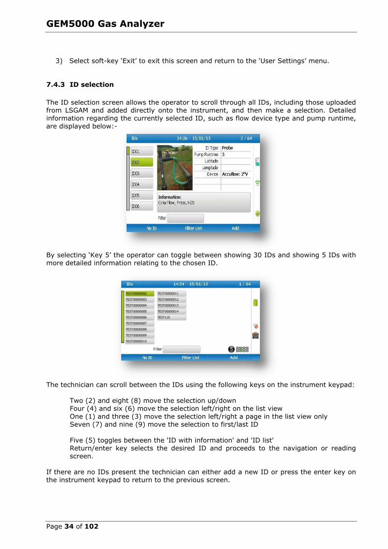
7.4.3 ID selection
The ID selection screen allows the operator to scroll through all IDs, including those uploaded from LSGAM and added directly onto the instrument, and then make a selection. Detailed
information regarding the currently selected ID, such as flow device type and pump runtime, are displayed below:-
By selecting ‘Key 5’ the operator can toggle between showing 30 IDs and showing 5 IDs with
more detailed information relating to the chosen ID.
The technician can scroll between the IDs using the following keys on the instrument keypad:
Two (2) and eight (8) move the selection up/down Four (4) and six (6) move the selection left/right on the list view
One (1) and three (3) move the selection left/right a page in the list view only Seven (7) and nine (9) move the selection to first/last ID
Five (5) toggles between the 'ID with information' and 'ID list' Return/enter key selects the desired ID and proceeds to the navigation or reading
screen.
If there are no IDs present the technician can either add a new ID or press the enter key on the instrument keypad to return to the previous screen.

GEM5000 Gas Analyzer
Page 35 of 102
Soft keys:
Left - Select 'No ID' and go to the purge/reading screen.
Center - Enabled when there is a list of IDs, allowing the technician to dynamically
filter the IDs displayed in the list. Right - Allows the technician to add a new ID to the instrument 'in the field'.
Note: If your analyzer has firmware version v1.12 or greater, used IDs will have a
strikethrough.
Changing the sort order
By default the IDs are sorted in the order in which they were transferred to the instrument.
To change the sort order between unsorted, sort by name or sorted by distance to travel press Key 0.
Sorted by original order (not sorted)
Sorted alphabetically
Sorted by distance to travel
Note: Only available when GPS is enabled
For analyzers with firmware v1.12 and above:
1) Press the menu key
2) Press the middle soft key for ‘User Settings’
3) Press key 3 – ‘ID options
a. Key 1 to change the sort order b. Key 2 to change how the IDs are displayed
c. Key 3 to clear the line through on the current ID being used d. Key 4 to remove the line through on all IDs
GEM5000 Gas Analyzer
Page 36 of 102
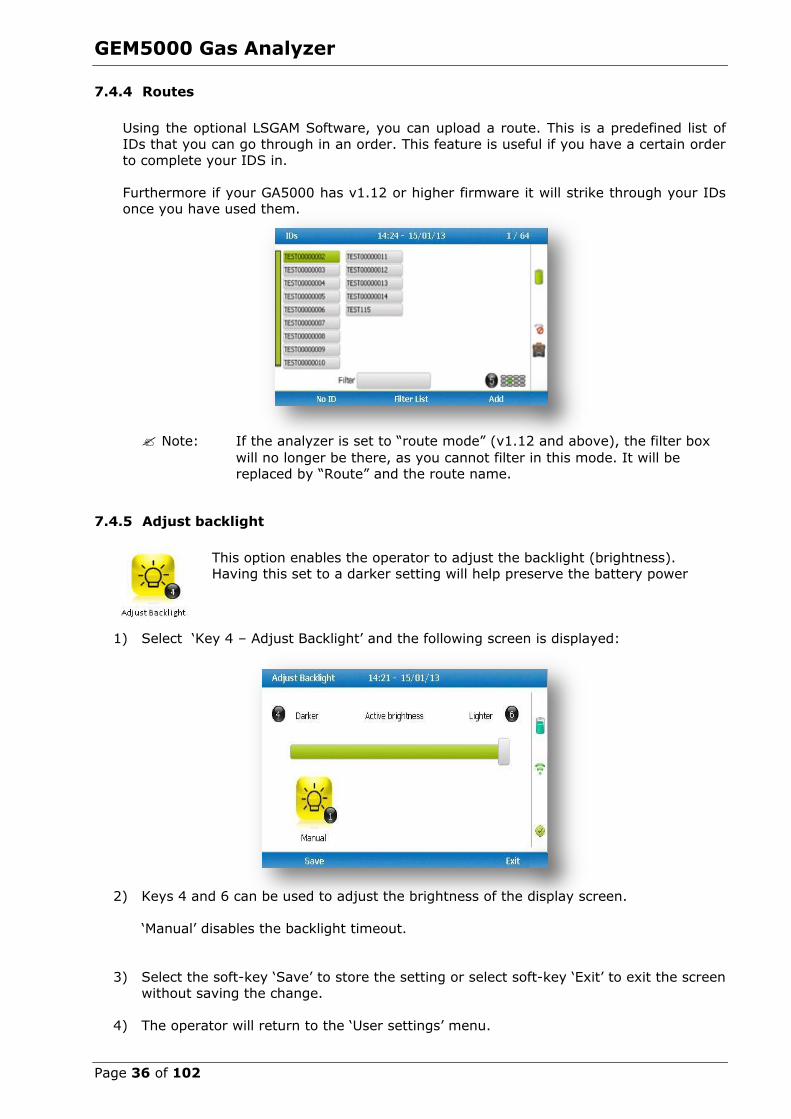
7.4.4 Routes
Using the optional LSGAM Software, you can upload a route. This is a predefined list of
IDs that you can go through in an order. This feature is useful if you have a certain order
to complete your IDS in.
Furthermore if your GA5000 has v1.12 or higher firmware it will strike through your IDs once you have used them.
Note: If the analyzer is set to “route mode” (v1.12 and above), the filter box
will no longer be there, as you cannot filter in this mode. It will be replaced by “Route” and the route name.
7.4.5 Adjust backlight
This option enables the operator to adjust the backlight (brightness). Having this set to a darker setting will help preserve the battery power
1) Select ‘Key 4 – Adjust Backlight’ and the following screen is displayed:
2) Keys 4 and 6 can be used to adjust the brightness of the display screen.
‘Manual’ disables the backlight timeout.
3) Select the soft-key ‘Save’ to store the setting or select soft-key ‘Exit’ to exit the screen
without saving the change.
4) The operator will return to the ‘User settings’ menu.
GEM5000 Gas Analyzer
Page 37 of 102
Selecting ‘Key 1’ allows the operator to configure the dimmer settings from ‘Auto Dim’
to ‘Auto Off’ in order to help preserve power consumption when data logging.
This icon represents ‘Auto Dim’ – this enables the backlight idle timeout, which means the backlight will go dim after a specified period of inactivity. This will help save
battery life.
This icon represents ‘Auto Off’ – this switches the backlight off, saving power.
Note: The manually set contrast setting is retained when the read-out is
switched off and may require resetting when next switched on.
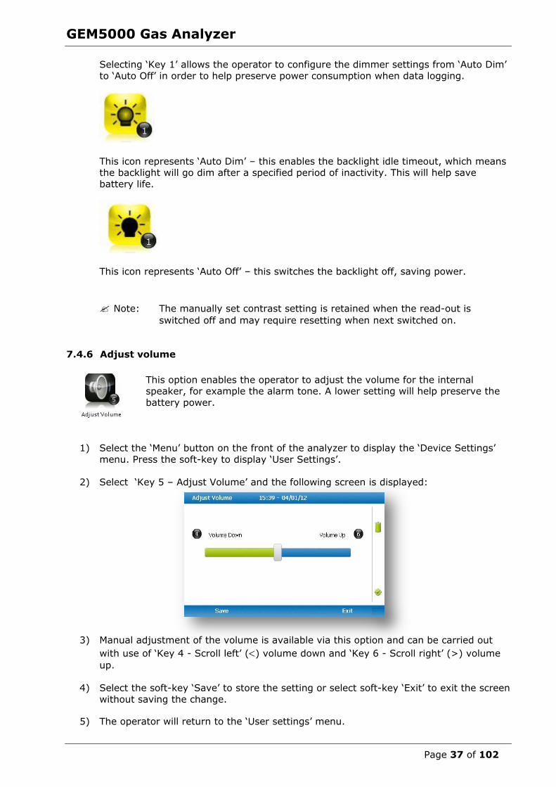
7.4.6 Adjust volume
This option enables the operator to adjust the volume for the internal speaker, for example the alarm tone. A lower setting will help preserve the
battery power.
1) Select the ‘Menu’ button on the front of the analyzer to display the ‘Device Settings’
menu. Press the soft-key to display ‘User Settings’.
2) Select ‘Key 5 – Adjust Volume’ and the following screen is displayed:
3) Manual adjustment of the volume is available via this option and can be carried out
with use of ‘Key 4 - Scroll left’ () volume down and ‘Key 6 - Scroll right’ (>) volume
up.
4) Select the soft-key ‘Save’ to store the setting or select soft-key ‘Exit’ to exit the screen
without saving the change.
5) The operator will return to the ‘User settings’ menu.

GEM5000 Gas Analyzer
Page 38 of 102
7.4.7 User Prompts
This option enables the operator to either turn on or off the context-sensitive
user prompts which are displayed during the gas sample process. The analyzer
will have the user prompts on when it is first used, so if they are no required they can be switched off by selecting soft-key ‘6’ and this will now be its
default setting. Prompts can be switched back on at any time by returning to this menu and selecting soft-key ‘6’.
7.5 Exit menu
1) Press the ‘Menu’ button on the front of the analyzer to exit settings.

GEM5000 Gas Analyzer
Page 39 of 102
8.0 Taking Readings
8.1 Preliminary checks before taking readings (best practice)
Prior to use, it is good practice to ensure
that:
Step 1 If using LSGAM - all necessary ID codes and information have been
uploaded from LSGAM to the analyzer. Please see section 8.1.1
for more information on this.
Step 2 Check the ‘Mode of Operation’ is
correct. Choose either GEM5000 for gas extraction monitoring
analyzer or GA5000 for landfill gas analyzer. Change using ‘Special
Actions’.
Step 3 The instrument has the correct time and date set.
Step 4 The water trap filter is fitted and is clean and dry.
Step 5 The battery has a good charge
(minimum 25% charge, even if only a few readings are required).
Step 6 The gas channels have been
zeroed, without gas concentration
present.
Step 7 If necessary check the span calibration with a known
concentration calibration gas.
Step 8 Take readings.
Start
ID codes and
information
uploaded
Battery has
good charge
Check span
calibration
Take readings
Step 1
Step 2
Step 6
Analyser
has correct time
and date set
Check mode of
operation is correct
(GEM /GA)
Water trap filter is
clean and dry
Gases
zeroed
Step 3
Step 4
Step 5
Step 7
Step 8

GEM5000 Gas Analyzer
Page 40 of 102
Warning Inhaling hydrogen sulphide gas (H2S) or other harmful gases can cause death. It is the responsibility of the user to ensure that he/she is
adequately trained in the safety aspects of using H2S and other harmful gases. In particular, where hazardous gases are being used the gas
exhausted from the analyser must be piped to an area where it is safe to discharge the gas. Hazardous gas can also be expelled from the
instrument when purging with clean air.
Good practice
Travel to site with the gas analyzer in the vehicle's interior - not in the trunk or truck
bed, where it may be subjected to extremes of temperature and possible shock damage. Do not place the gas analyzer against anything hot (e.g. gas extraction
pipe, car body or in an unattended car during the summer) as this will cause a temperature increase in the gas analyzer and may cause erroneous readings.
When moving around a site, protect the gas analyzer from strong direct sunlight and
heavy rain.
Always use the water trap! If the water trap becomes flooded, change the filter and
ensure all tubes are clear of moisture before re-use.
Note: If the exhaust of a 5000 series gas analyzer is connected to a
pressurized system then this results in a flow of gas out of the inlet flow port.
GEM5000 Gas Analyzer
Page 41 of 102
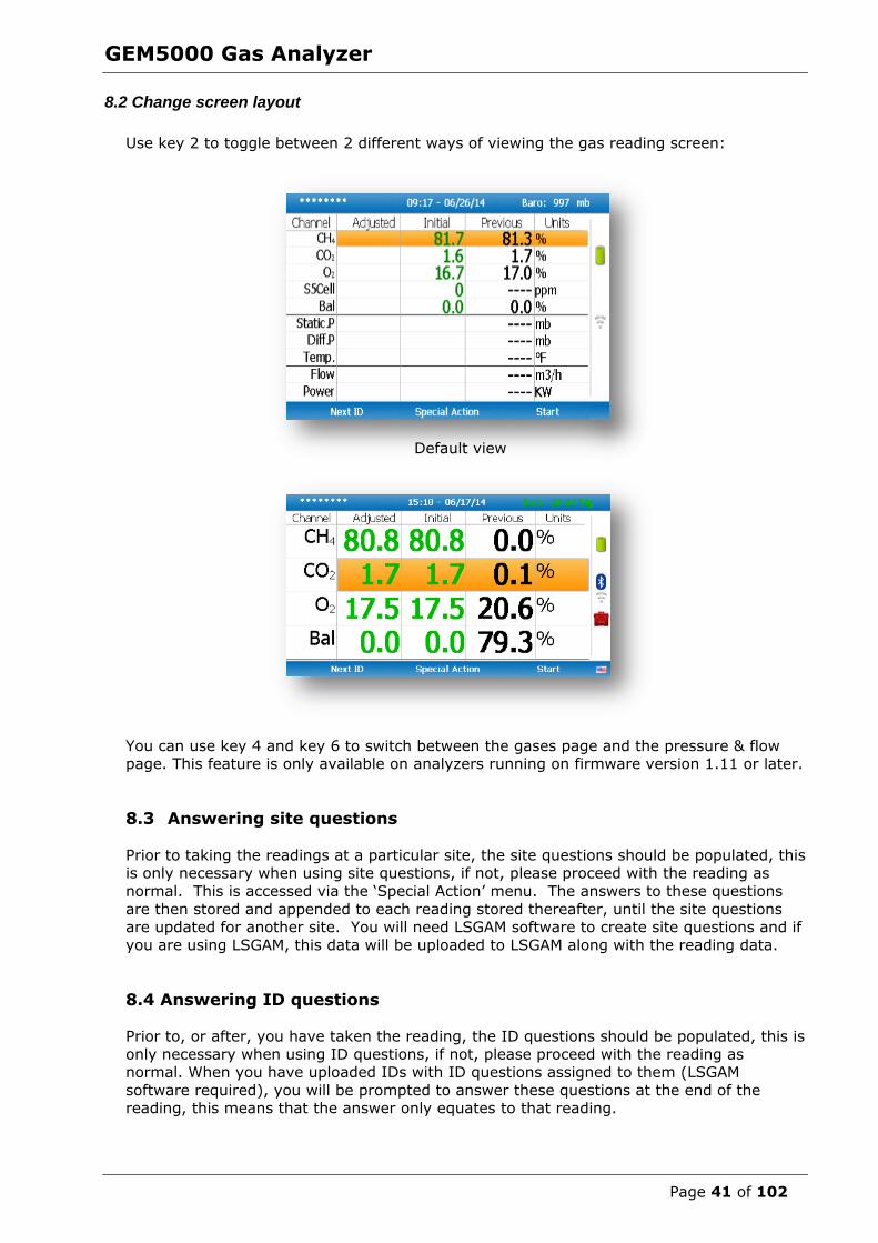
8.2 Change screen layout
Use key 2 to toggle between 2 different ways of viewing the gas reading screen:
Default view
You can use key 4 and key 6 to switch between the gases page and the pressure & flow page. This feature is only available on analyzers running on firmware version 1.11 or later.
8.3 Answering site questions
Prior to taking the readings at a particular site, the site questions should be populated, this is only necessary when using site questions, if not, please proceed with the reading as
normal. This is accessed via the ‘Special Action’ menu. The answers to these questions
are then stored and appended to each reading stored thereafter, until the site questions are updated for another site. You will need LSGAM software to create site questions and if
you are using LSGAM, this data will be uploaded to LSGAM along with the reading data.
8.4 Answering ID questions
Prior to, or after, you have taken the reading, the ID questions should be populated, this is
only necessary when using ID questions, if not, please proceed with the reading as normal. When you have uploaded IDs with ID questions assigned to them (LSGAM
software required), you will be prompted to answer these questions at the end of the reading, this means that the answer only equates to that reading.

GEM5000 Gas Analyzer
Page 42 of 102
8.5 Special action This menu enables the operator to perform the additional following functions out of
sequence if so desired.
1) From the ‘Main Gas Read Screen’ select the soft-key ‘Special Action’ and the following menu is displayed:
Note: The list of special action options displayed on the special action menu is
dependent upon device type and sequence.
The following actions may be available:
Action Function
Key 1 – Simple Gas This action enables the operator to take a quick gas reading. The pump will start running automatically when
this key is selected. The operator can stop the pump by pressing the pump key on the keypad at any time and
the reading can then be stored by selecting soft-key ‘Store’.
Key 2 – Site Questions This action enables the operator to update site questions
prior to taking a reading.
Key 3 – ID Questions This action enables the operator to update ID questions
specific to sample points prior to taking a reading. Key 4 – Flow This action enables the operator to measure internal flow
first when taking a reading. Connect the blue hose to the sample point. The yellow hose can be vented a safe
distance from the sample point or re-circulated back into the system. Select either soft-key ‘Zero Flow’,’ Flow
Options’ or ‘Start’ to commence internal flow. Select
soft-key ‘Store’ to store and record the reading.
Key 5 – Enter Temperature This action enables the operator to manually enter a temperature reading if not using a temperature probe
prior to taking a gas measurement.
Key 6 – Start Logging This action enables the operator to leave the analyzer unattended to take samples at a predetermined time.
The reading interval and pump run times may be edited
prior to commencing the logging cycle.

GEM5000 Gas Analyzer
Page 43 of 102
8.5.1 Configuration of the data logging option
1) Connect the gas inlet (white port) to the sample point. The yellow exhaust hose can
be vented a safe distance from the sample point; do NOT re-circulate back into the
system. 2) By selecting ‘Next ID’ the operator can select the ID which is being sampled at
present. 3) Once the ID has been chosen the analyzer will commence and complete its clean air
purge cycle. 4) To gain access to the data logging option the operator will be required to select the
’Special Action’ key to obtain the special user options. The data logging option can then be selected via ‘Key 6’ to configure the logging parameters.
5) Once the operator has confirmed the logging parameters, select soft-key ‘Start
Logging’. 6) Once the logging function has been activated the analyzer will carry out a 30 second
warm-up (displayed below the temperature read out at the right of the main gas read screen) and begin the first sample.
7) If for any reason during the logging cycle the inlet port becomes blocked, the analyzer will sense this as a ‘Flow Fail’ and the pump will automatically retry until the
reading can be obtained. As such care must be taken when positioning the sample tubing to ensure water/moisture ingress does not occur.
8) Select soft-key ‘Stop Logging’ to stop logging if required.
8.5.2 Profiling option
1) The ‘Logging Mode’ center soft-key toggles between ‘Logging Mode’ and ‘Profiling Mode’ and pressing it will change the mode to the one the soft-key describes. For
example, when on the profiling page the key will display as ‘Logging Mode’ and when on the logging page the key will display as ‘Profiling Mode’.
2) To edit the parameter the operator will be required to select ‘Key 3’ to select the
number of reading required. Once the number of readings has been updated press
the return key to confirm parameter setting. 3) By selecting ‘Key 2’ the operator can edit the logging interval of their logging
preferences and then confirm the amendments by pressing the return key. 4) Once the logging parameters are confirmed, commence the logging by selecting
the ‘Start Logging’ key. 5) If for any reason during the logging cycle the inlet port becomes blocked, the
analyzer will sense this as a ‘Flow Fail’ and the pump will automatically retry until the reading can be obtained. As such care must be taken when positioning the
sample tubing to ensure water/moisture ingress does not occur.
6) Select soft-key ‘Stop Logging’ to stop logging if required.
Select the soft-key ‘Exit’ to exit this menu and return to the ‘Main Gas Read Screen’.
GEM5000 Gas Analyzer
Page 44 of 102
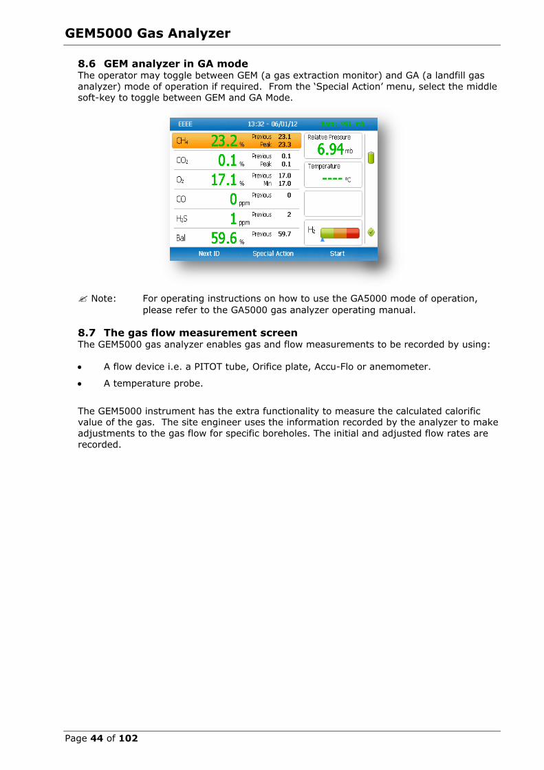
8.6 GEM analyzer in GA mode The operator may toggle between GEM (a gas extraction monitor) and GA (a landfill gas
analyzer) mode of operation if required. From the ‘Special Action’ menu, select the middle soft-key to toggle between GEM and GA Mode.
Note: For operating instructions on how to use the GA5000 mode of operation,
please refer to the GA5000 gas analyzer operating manual.
8.7 The gas flow measurement screen The GEM5000 gas analyzer enables gas and flow measurements to be recorded by using:
A flow device i.e. a PITOT tube, Orifice plate, Accu-Flo or anemometer.
A temperature probe.
The GEM5000 instrument has the extra functionality to measure the calculated calorific value of the gas. The site engineer uses the information recorded by the analyzer to make
adjustments to the gas flow for specific boreholes. The initial and adjusted flow rates are
recorded.
GEM5000 Gas Analyzer
Page 45 of 102
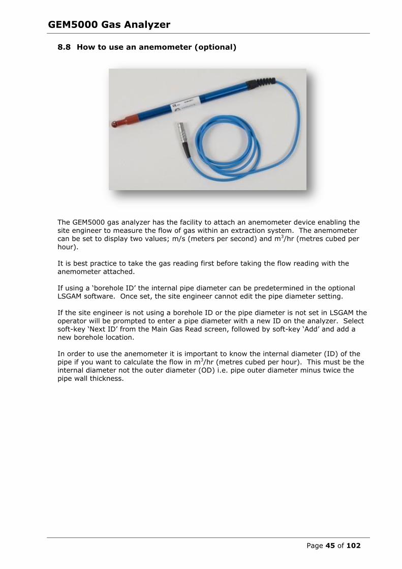
8.8 How to use an anemometer (optional)
The GEM5000 gas analyzer has the facility to attach an anemometer device enabling the
site engineer to measure the flow of gas within an extraction system. The anemometer can be set to display two values; m/s (meters per second) and m3/hr (metres cubed per
hour).
It is best practice to take the gas reading first before taking the flow reading with the
anemometer attached.
If using a ‘borehole ID’ the internal pipe diameter can be predetermined in the optional LSGAM software. Once set, the site engineer cannot edit the pipe diameter setting.
If the site engineer is not using a borehole ID or the pipe diameter is not set in LSGAM the
operator will be prompted to enter a pipe diameter with a new ID on the analyzer. Select soft-key ‘Next ID’ from the Main Gas Read screen, followed by soft-key ‘Add’ and add a
new borehole location.
In order to use the anemometer it is important to know the internal diameter (ID) of the
pipe if you want to calculate the flow in m3/hr (metres cubed per hour). This must be the internal diameter not the outer diameter (OD) i.e. pipe outer diameter minus twice the
pipe wall thickness.
GEM5000 Gas Analyzer
Page 46 of 102
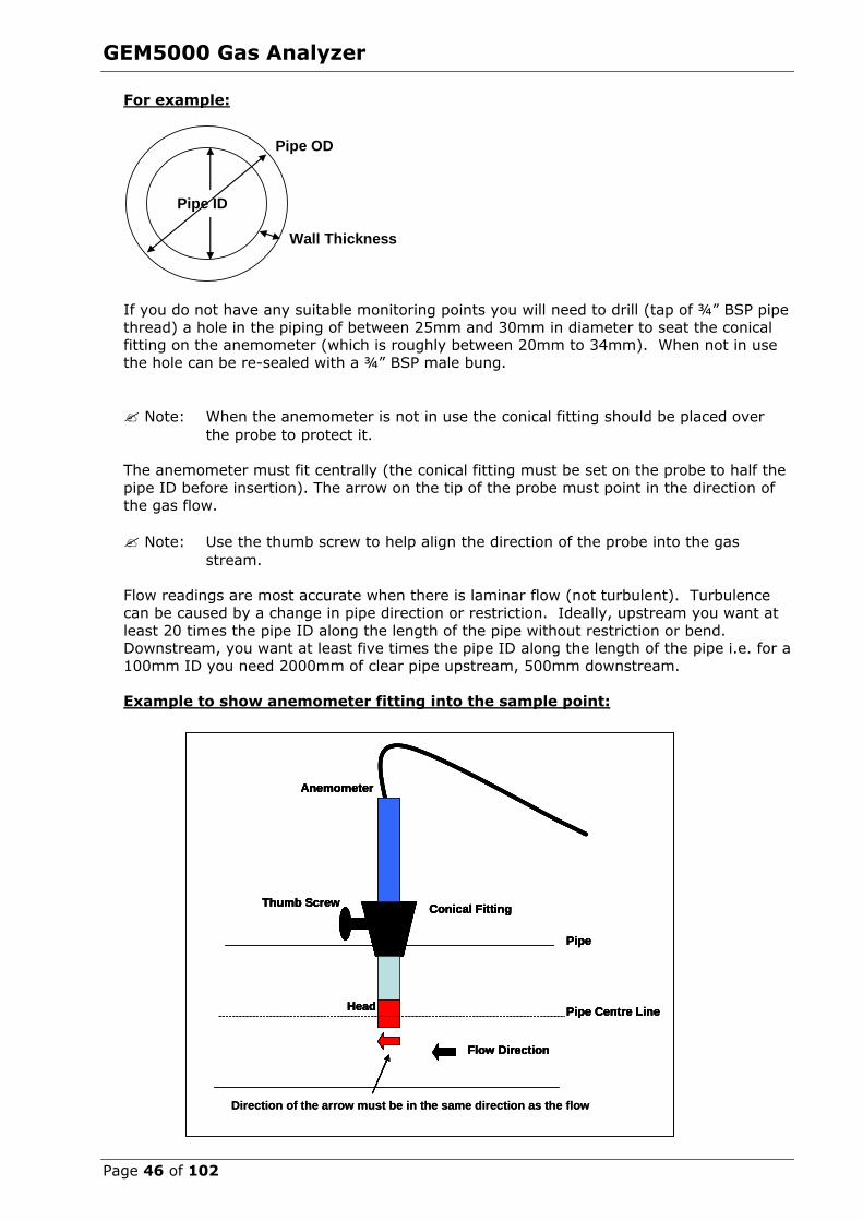
For example:
If you do not have any suitable monitoring points you will need to drill (tap of ¾” BSP pipe
thread) a hole in the piping of between 25mm and 30mm in diameter to seat the conical fitting on the anemometer (which is roughly between 20mm to 34mm). When not in use
the hole can be re-sealed with a ¾” BSP male bung.
Note: When the anemometer is not in use the conical fitting should be placed over
the probe to protect it.
The anemometer must fit centrally (the conical fitting must be set on the probe to half the
pipe ID before insertion). The arrow on the tip of the probe must point in the direction of
the gas flow.
Note: Use the thumb screw to help align the direction of the probe into the gas
stream.
Flow readings are most accurate when there is laminar flow (not turbulent). Turbulence can be caused by a change in pipe direction or restriction. Ideally, upstream you want at
least 20 times the pipe ID along the length of the pipe without restriction or bend. Downstream, you want at least five times the pipe ID along the length of the pipe i.e. for a
100mm ID you need 2000mm of clear pipe upstream, 500mm downstream.
Example to show anemometer fitting into the sample point:
Pipe ID
Pipe OD
Wall Thickness
Conical Fitting
Pipe Centre Line
Pipe
Head
Flow Direction
Thumb Screw
Anemometer
Conical Fitting
Pipe Centre Line
Pipe
Head
Direction of the arrow must be in the same direction as the flow
Flow Direction
Thumb Screw
Anemometer
Conical Fitting
Pipe Centre Line
Pipe
Head
Flow Direction
Thumb Screw
Anemometer
Conical Fitting
Pipe Centre Line
Pipe
Head
Direction of the arrow must be in the same direction as the flow
Flow Direction
Thumb Screw
Anemometer
GEM5000 Gas Analyzer
Page 47 of 102
Instructions for use:
1) Attach the anemometer to ‘Connector C’ (refer to section 5.3 – Instrument
connection points).
2) Place the anemometer into the pipe (sample point) ready to take the reading.
3) To take a flow measurement when using an anemometer, follow the instructions displayed on the analyzer. When the reading has stabilized press the ‘Enter’ key to
store the reading.
Anemometer cleaning instructions:
General handling tips:
Protect the probes against severe vibration.
Do not kink the connector cable (risk of cable breakage). Never allow hard objects to contact rotating impellers.
Always carry out probe cleaning according to the cleaning instructions.
Never immerse probes in solvent. Never blow probes through with compressed air.
Allow hot probes to cool slowly, never cool by plunging them in cold water etc.
Cleaning instructions:
Instrument and probe must be switched off or disconnected prior to cleaning.
Vane probes:
As the probes are highly sensitive measuring instruments, they must be cleaned with
great care. Fibres or other foreign bodies can be carefully removed with fine tweezers. When
doing so, take care not to bend or otherwise damage the vanes or the spindle. The adjustment of the bearing screws must never be changed. This can result in an
erroneous measurement. Never allow hard objects to contact rotating impellers.
Cleaning agents that extract the plasticizer from the plastic are never to be used for
plastic probes (practically all solvents).
Cleaning the probes – best practice:
Note: Use soapy water.
Cleaning example:
1) Carefully, swish the top part of the impeller back and forth in clean soapy water for
approximately 10 minutes. Then swish the top part of the impeller back and forth in
clean soapy water. If soapy water is used as a cleaning agent it is advisable to wash out the soap solution thoroughly with distilled water.
2) After cleaning the probe, rub it dry with a clean, dry cloth.

GEM5000 Gas Analyzer
Page 48 of 102
8.9 How to use a pitot tube (optional) The GEM5000 gas analyzer enables the site engineer to take gas measurements using a
pitot tube. The pitot tube is used for gas extraction systems and the pressure readings are taken in mbar. Gas flow is calculated in the analyzer in m3/hr (metres cubed per
hour).
Example of a pitot tube
Fitting a pitot tube to the analyzer:
1) It is important to seat the pitot tube into the monitoring point with the tip facing into the gas flow. The pitot tube should also be housed half way down the monitoring
pipe. (Please refer to the anemometer instructions, which detail how to calculate the pipe diameter correctly).
2) Make sure that the sample tubing attached to the pitot tube fits correctly.
3) Attach the sample tube from the top connection of the pitot tube to the ‘blue port’ (the differential port) on the analyser making sure that the gas port connector secure
into place.
4) Attach the sample tube from the side of the pitot tube to the ‘white port’ (inlet port/static pressure port) on the analyser making sure that the gas port connector
secures into place.
5) House the pitot gland correctly onto the monitoring point.
6) When taking a gas reading and flow measurement follow the instruction as displayed
on the front of the instrument.
Note: Please refer to the following section for a diagram showing how to fit the
tubing to the pitot tube.
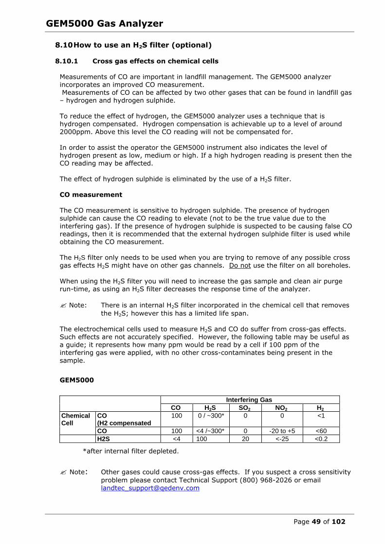
GEM5000 Gas Analyzer
Page 49 of 102
8.10 How to use an H2S filter (optional)
8.10.1 Cross gas effects on chemical cells
Measurements of CO are important in landfill management. The GEM5000 analyzer incorporates an improved CO measurement.
Measurements of CO can be affected by two other gases that can be found in landfill gas – hydrogen and hydrogen sulphide.
To reduce the effect of hydrogen, the GEM5000 analyzer uses a technique that is hydrogen compensated. Hydrogen compensation is achievable up to a level of around
2000ppm. Above this level the CO reading will not be compensated for.
In order to assist the operator the GEM5000 instrument also indicates the level of hydrogen present as low, medium or high. If a high hydrogen reading is present then the
CO reading may be affected.
The effect of hydrogen sulphide is eliminated by the use of a H2S filter.
CO measurement
The CO measurement is sensitive to hydrogen sulphide. The presence of hydrogen
sulphide can cause the CO reading to elevate (not to be the true value due to the interfering gas). If the presence of hydrogen sulphide is suspected to be causing false CO
readings, then it is recommended that the external hydrogen sulphide filter is used while obtaining the CO measurement.
The H2S filter only needs to be used when you are trying to remove of any possible cross
gas effects H2S might have on other gas channels. Do not use the filter on all boreholes.
When using the H2S filter you will need to increase the gas sample and clean air purge run-time, as using an H2S filter decreases the response time of the analyzer.
Note: There is an internal H2S filter incorporated in the chemical cell that removes
the H2S; however this has a limited life span.
The electrochemical cells used to measure H2S and CO do suffer from cross-gas effects.
Such effects are not accurately specified. However, the following table may be useful as a guide; it represents how many ppm would be read by a cell if 100 ppm of the
interfering gas were applied, with no other cross-contaminates being present in the
sample.
GEM5000
Interfering Gas
CO H2S SO2 NO2 H2
Chemical Cell
CO (H2 compensated
100 0 / ~300* 0 0 <1
CO 100 <4 /~300* 0 -20 to +5 <60
H2S <4 100 20 <-25 <0.2
*after internal filter depleted.
Note: Other gases could cause cross-gas effects. If you suspect a cross sensitivity
problem please contact Technical Support (800) 968-2026 or email
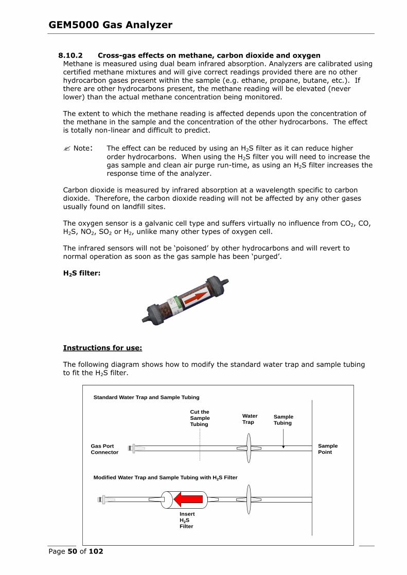
GEM5000 Gas Analyzer
Page 50 of 102
8.10.2 Cross-gas effects on methane, carbon dioxide and oxygen Methane is measured using dual beam infrared absorption. Analyzers are calibrated using
certified methane mixtures and will give correct readings provided there are no other
hydrocarbon gases present within the sample (e.g. ethane, propane, butane, etc.). If there are other hydrocarbons present, the methane reading will be elevated (never
lower) than the actual methane concentration being monitored.
The extent to which the methane reading is affected depends upon the concentration of the methane in the sample and the concentration of the other hydrocarbons. The effect
is totally non-linear and difficult to predict.
Note: The effect can be reduced by using an H2S filter as it can reduce higher
order hydrocarbons. When using the H2S filter you will need to increase the
gas sample and clean air purge run-time, as using an H2S filter increases the response time of the analyzer.
Carbon dioxide is measured by infrared absorption at a wavelength specific to carbon
dioxide. Therefore, the carbon dioxide reading will not be affected by any other gases
usually found on landfill sites.
The oxygen sensor is a galvanic cell type and suffers virtually no influence from CO2, CO, H2S, NO2, SO2 or H2, unlike many other types of oxygen cell.
The infrared sensors will not be ‘poisoned’ by other hydrocarbons and will revert to
normal operation as soon as the gas sample has been ‘purged’.
H2S filter:
Instructions for use:
The following diagram shows how to modify the standard water trap and sample tubing
to fit the H2S filter.
Sample
Point
Sample
Tubing
Cut the
Sample
Tubing
Water
Trap
Insert
H2S
Filter
Gas Port
Connector
Standard Water Trap and Sample Tubing
Modified Water Trap and Sample Tubing with H2S Filter
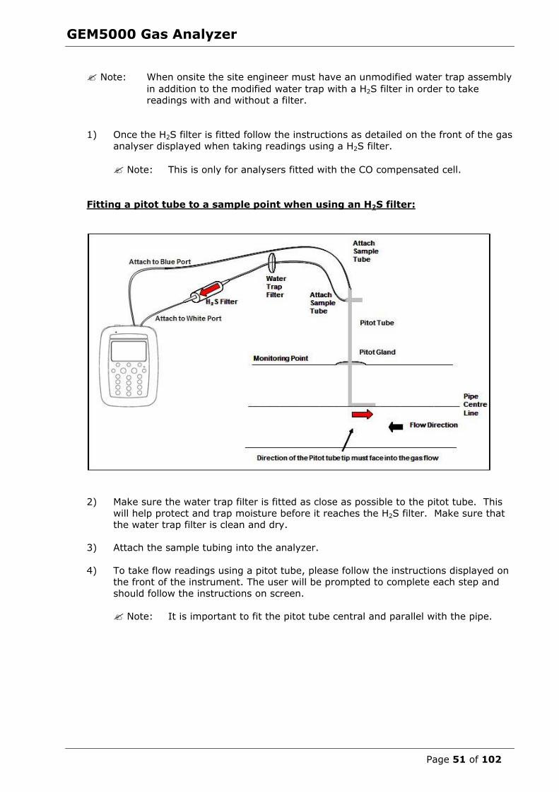
GEM5000 Gas Analyzer
Page 51 of 102
Note: When onsite the site engineer must have an unmodified water trap assembly
in addition to the modified water trap with a H2S filter in order to take readings with and without a filter.
1) Once the H2S filter is fitted follow the instructions as detailed on the front of the gas
analyser displayed when taking readings using a H2S filter.
Note: This is only for analysers fitted with the CO compensated cell.
Fitting a pitot tube to a sample point when using an H2S filter:
2) Make sure the water trap filter is fitted as close as possible to the pitot tube. This
will help protect and trap moisture before it reaches the H2S filter. Make sure that the water trap filter is clean and dry.
3) Attach the sample tubing into the analyzer.
4) To take flow readings using a pitot tube, please follow the instructions displayed on the front of the instrument. The user will be prompted to complete each step and
should follow the instructions on screen.
Note: It is important to fit the pitot tube central and parallel with the pipe.

GEM5000 Gas Analyzer
Page 52 of 102
8.11 How to use a temperature probe (optional) The temperature probe enables the site engineer to measure the temperature of the gas
within a sample point. The GEM5000 gas analyzer uses the temperature of the gas to give more accurate flow measurement readings as part of the instrument calculation.
Instructions for use:
1) The temperature probe reading is taken along with the gas measurement reading.
2) The analyzer must be at the ‘Main Gas Read Screen’.
3) Attach the temperature probe to ‘connector B’ (refer to section 5.3 – Instrument
connections points).
4) Insert the temperature probe into the sample point (borehole) at the same time as
you attach the sample tube to the sample point (two sample points are required for the borehole).
5) Follow the instructions on the front of the instrument when taking your gas and
measurement reading.
6) At the point in which the operator presses ‘Enter’ to store the gas reading the temperature is recorded.
Note: Temperature probe readings can be analysed further when downloaded
to LSGAM.
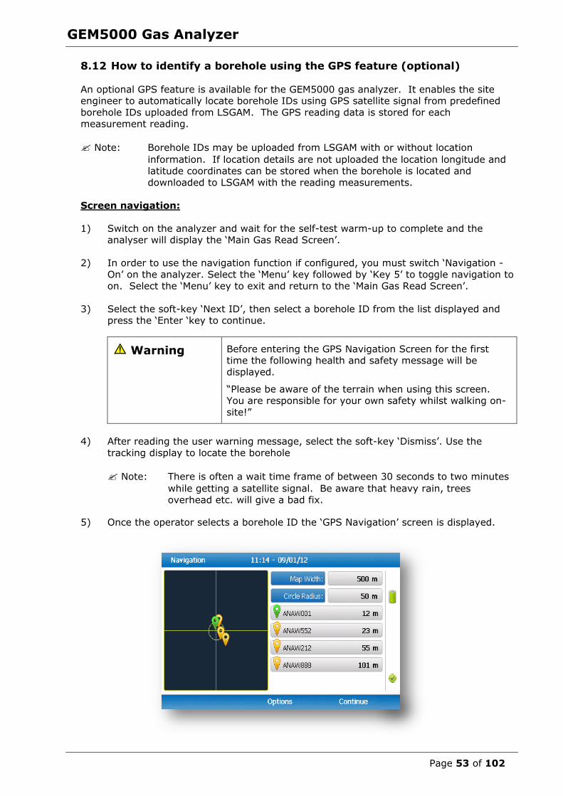
GEM5000 Gas Analyzer
Page 53 of 102
8.12 How to identify a borehole using the GPS feature (optional)
An optional GPS feature is available for the GEM5000 gas analyzer. It enables the site engineer to automatically locate borehole IDs using GPS satellite signal from predefined
borehole IDs uploaded from LSGAM. The GPS reading data is stored for each measurement reading.
Note: Borehole IDs may be uploaded from LSGAM with or without location
information. If location details are not uploaded the location longitude and
latitude coordinates can be stored when the borehole is located and
downloaded to LSGAM with the reading measurements.
Screen navigation:
1) Switch on the analyzer and wait for the self-test warm-up to complete and the analyser will display the ‘Main Gas Read Screen’.
2) In order to use the navigation function if configured, you must switch ‘Navigation -
On’ on the analyzer. Select the ‘Menu’ key followed by ‘Key 5’ to toggle navigation to
on. Select the ‘Menu’ key to exit and return to the ‘Main Gas Read Screen’.
3) Select the soft-key ‘Next ID’, then select a borehole ID from the list displayed and press the ‘Enter ‘key to continue.
Warning Before entering the GPS Navigation Screen for the first time the following health and safety message will be
displayed.
“Please be aware of the terrain when using this screen.
You are responsible for your own safety whilst walking on-
site!”
4) After reading the user warning message, select the soft-key ‘Dismiss’. Use the
tracking display to locate the borehole
Note: There is often a wait time frame of between 30 seconds to two minutes
while getting a satellite signal. Be aware that heavy rain, trees overhead etc. will give a bad fix.
5) Once the operator selects a borehole ID the ‘GPS Navigation’ screen is displayed.
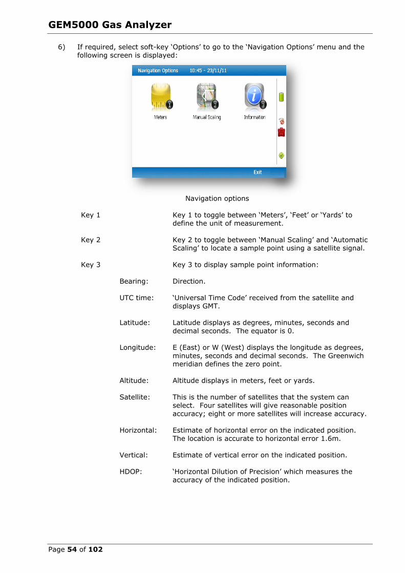
GEM5000 Gas Analyzer
Page 54 of 102
6) If required, select soft-key ‘Options’ to go to the ‘Navigation Options’ menu and the
following screen is displayed:
Navigation options
Key 1 Key 1 to toggle between ‘Meters’, ‘Feet’ or ‘Yards’ to
define the unit of measurement.
Key 2 Key 2 to toggle between ‘Manual Scaling’ and ‘Automatic Scaling’ to locate a sample point using a satellite signal.
Key 3 Key 3 to display sample point information:
Bearing: Direction.
UTC time: ‘Universal Time Code’ received from the satellite and displays GMT.
Latitude:
Latitude displays as degrees, minutes, seconds and
decimal seconds. The equator is 0.
Longitude:
E (East) or W (West) displays the longitude as degrees,
minutes, seconds and decimal seconds. The Greenwich meridian defines the zero point.
Altitude: Altitude displays in meters, feet or yards.
Satellite: This is the number of satellites that the system can
select. Four satellites will give reasonable position
accuracy; eight or more satellites will increase accuracy.
Horizontal: Estimate of horizontal error on the indicated position. The location is accurate to horizontal error 1.6m.
Vertical: Estimate of vertical error on the indicated position.
HDOP:
‘Horizontal Dilution of Precision’ which measures the
accuracy of the indicated position.
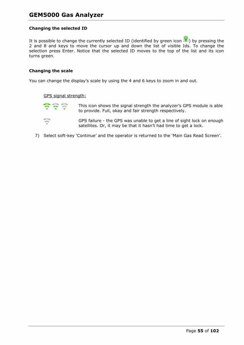
GEM5000 Gas Analyzer
Page 55 of 102
Changing the selected ID
It is possible to change the currently selected ID (identified by green icon ) by pressing the
2 and 8 and keys to move the cursor up and down the list of visible Ids. To change the
selection press Enter. Notice that the selected ID moves to the top of the list and its icon
turns green.
Changing the scale
You can change the display’s scale by using the 4 and 6 keys to zoom in and out.
GPS signal strength:
This icon shows the signal strength the analyzer’s GPS module is able
to provide. Full, okay and fair strength respectively.
GPS failure - the GPS was unable to get a line of sight lock on enough satellites. Or, it may be that it hasn’t had time to get a lock.
7) Select soft-key ‘Continue’ and the operator is returned to the ‘Main Gas Read Screen’.
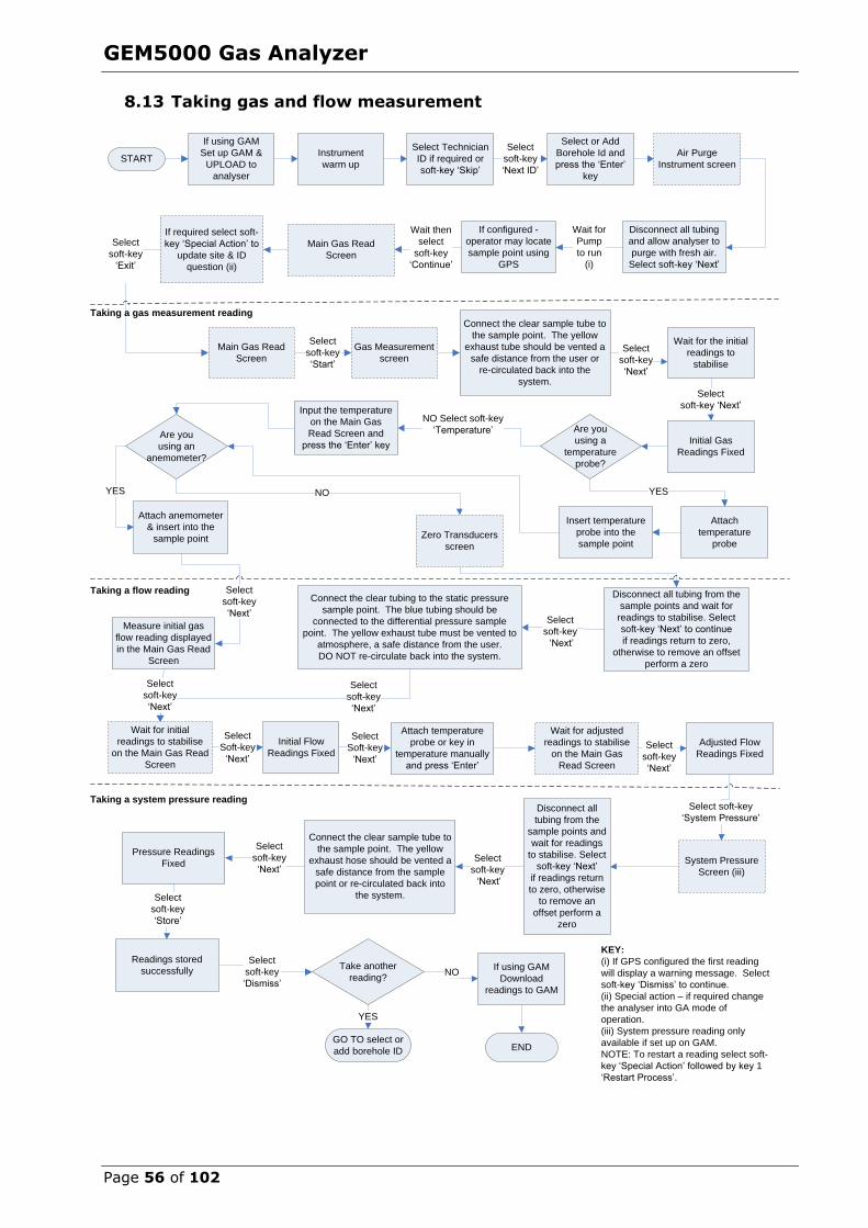
GEM5000 Gas Analyzer
Page 56 of 102
8.13 Taking gas and flow measurement
9.0 Calibration
9.1 Calibration introduction
START
END
If using GAM
Set up GAM &
UPLOAD to
analyser
Air Purge
Instrument screen
Disconnect all tubing
and allow analyser to
purge with fresh air.
Select soft-key ‘Next’
If using GAM
Download
readings to GAM
Select
soft-key
‘Next’
GO TO select or
add borehole ID
YES
Zero Transducers
screen
Select Technician
ID if required or
soft-key ‘Skip’
Select
soft-key
‘Next ID’
Main Gas Read
Screen
Instrument
warm up
Disconnect all tubing from the
sample points and wait for
readings to stabilise. Select
soft-key ‘Next’ to continue
if readings return to zero,
otherwise to remove an offset
perform a zero
Connect the clear tubing to the static pressure
sample point. The blue tubing should be
connected to the differential pressure sample
point. The yellow exhaust tube must be vented to
atmosphere, a safe distance from the user.
DO NOT re-circulate back into the system.
Select
soft-key
‘Next’
Are you
using a
temperature
probe?
Wait for
Pump
to run
(i)
Attach
temperature
probe
Insert temperature
probe into the
sample point
Measure initial gas
flow reading displayed
in the Main Gas Read
Screen
Attach temperature
probe or key in
temperature manually
and press ‘Enter’
Adjusted Flow
Readings Fixed
NO Select soft-key
‘Temperature’
Take another
reading?NO
Select
soft-key
‘Next’
Select or Add
Borehole Id and
press the ‘Enter’
key
If configured -
operator may locate
sample point using
GPS
Wait then
select
soft-key
‘Continue’
If required select soft-
key ‘Special Action’ to
update site & ID
question (ii)
Select
soft-key
‘Exit’
Main Gas Read
Screen
Gas Measurement
screen
Select
soft-key
‘Start’
Connect the clear sample tube to
the sample point. The yellow
exhaust tube should be vented a
safe distance from the user or
re-circulated back into the
system.
Wait for the initial
readings to
stabilise
Select
soft-key ‘Next’
Initial Gas
Readings Fixed
Select
soft-key
‘Next’
Select
soft-key
‘Next’
Wait for adjusted
readings to stabilise
on the Main Gas
Read Screen
System Pressure
Screen (iii)
Disconnect all
tubing from the
sample points and
wait for readings
to stabilise. Select
soft-key ‘Next’
if readings return
to zero, otherwise
to remove an
offset perform a
zero
Connect the clear sample tube to
the sample point. The yellow
exhaust hose should be vented a
safe distance from the sample
point or re-circulated back into
the system.
Pressure Readings
Fixed
Select
soft-key
‘Next’
Readings stored
successfully
Select
soft-key
‘Store’
Select
soft-key
‘Dismiss’
Wait for initial
readings to stabilise
on the Main Gas Read
Screen
Initial Flow
Readings Fixed
KEY:
(i) If GPS configured the first reading
will display a warning message. Select
soft-key ‘Dismiss’ to continue.
(ii) Special action – if required change
the analyser into GA mode of
operation.
(iii) System pressure reading only
available if set up on GAM.
NOTE: To restart a reading select soft-
key ‘Special Action’ followed by key 1
‘Restart Process’.
Are you
using an
anemometer?
Attach anemometer
& insert into the
sample point
YESYES NO
Select soft-key
‘System Pressure’
Select
Soft-key
‘Next’
Select
soft-key
‘Next’
Select
Soft-key
‘Next’
Taking a system pressure reading
Taking a flow reading
Taking a gas measurement reading
Select
soft-key
‘Next’
Input the temperature
on the Main Gas
Read Screen and
press the ‘Enter’ key

GEM5000 Gas Analyzer
Page 57 of 102
9.0 Calibration
9.1 Calibration Introduction
The GEM5000 gas analyzer is carefully calibrated at manufacture and when returned for
service. However, it is sometimes desirable to be able to carry out a calibration process between services.
This section outlines the correct procedures to enable the site engineer to field calibrate the gas analyzer.
Note: This does not replace the factory service and calibration. If this calibration is
completed incorrectly it may decrease the accuracy of the gas analyzer.
CH4, CO2 and O2 can be measured by GEM5000 gas analyzer as standard; these channels
can be user calibrated. The analyzers have other gas channel options that are specified at manufacture; these too can be calibrated. This section will describe in detail how to
calibrate the three standard gas channels plus the CO channel.
The GEM5000 instrument can have a H2 compensated CO channel. This option requires
that H2 is used in the calibration process and is also set out within this section.
For the other gas channel options contact QED for advice.
Two important terms that are used within this section are ‘Zero’ and ‘Span’.
Zero: The point at which the gas analyzer is calibrated when there is none of the target
gases present.
Span: The point at which the gas analyzer is calibrated when a known quantity of the target gas is present.
9.2 Frequency of calibration – best practice
The GEM5000 gas analyzers can be checked against a known concentration of gas, to give confidence that the analyzer is operating as expected at the time and conditions in which it
is being used.
It is recommended that the instrument is regularly serviced and calibrated by QED in
accordance with the due date on the instrument.
When defining the frequency of user calibration, the following are factors to be considered:
The frequency of use of the analyzer. (daily?/monthly?) The level of confidence and accuracy required for readings to be taken.
Historical user calibration data.
Site specific requirements or conditions. Historical understanding of expected readings on site.
Zeroing of the gas analyzer should be undertaken at the start of each day’s monitoring.
Use historical data to drive your frequency of calibration.
If there is no historical data a good starting point for a daily monitoring round is performing a calibration once every week or every other week.
The results of the calibrations will need to be recorded to monitor over time whether the frequency of calibration needs to be increased or decreased relative to the confidence
required.

GEM5000 Gas Analyzer
Page 58 of 102
The confidence required will be driven by the site specific / user requirements.
When undertaking the monitoring with an understanding of the history of the gas levels of
that site, a calibration check could be triggered if the readings measured are different to what is expected.
Note: For assistance please contact Technical Support at (800) 968-2026 or email
9.3 Calibration gases User calibration of a gas analyzer will greatly improve the data accuracy in the range of
the calibration gases used. This may cause less accurate readings of concentrations outside this calibrated range. Users should select the correct calibration gas for the
expected gas levels on their particular application.
To improve calibration at lower levels requires the use of gas mixtures 1 and 2.
To improve higher levels use gas mixture 3. For standard CO only 100ppm CO gas is needed.
For CO (H2 compensated) both CO 100ppm and H2 1000ppm gases are needed.
The following table indicates the different gas mixture canisters used for calibration:
Calibration gas CH4 CO2 O2
Mixture 1 5% 5% 6%
Mixture 2 5% 10% 0%
Mixture 3 60% 40% 0%
Calibration targets for gas cells are dependent on the gas/range and type of cell fitted.
Contact Technical Support for assistance.
These are for general use but other gas concentrations can be used.
Note: The above gases and most other gas concentrations can be supplied by QED.
For further information please contact Sales at (800) 624-2026 or email [email protected]
Warning Calibration gases can be dangerous.
For each gas used the appropriate material safety data sheet must be read and understood before proceeding.
9.4 Calibration set-up
Warning Do NOT attach the gas supply to the gas analyzer before putting the analyzer into the ‘Gas Check’ screen. Select
‘Check Spans’ from the ‘Operation Settings’ menu.
The regulator supplied with the calibration kit has been configured to deliver a fixed flow.
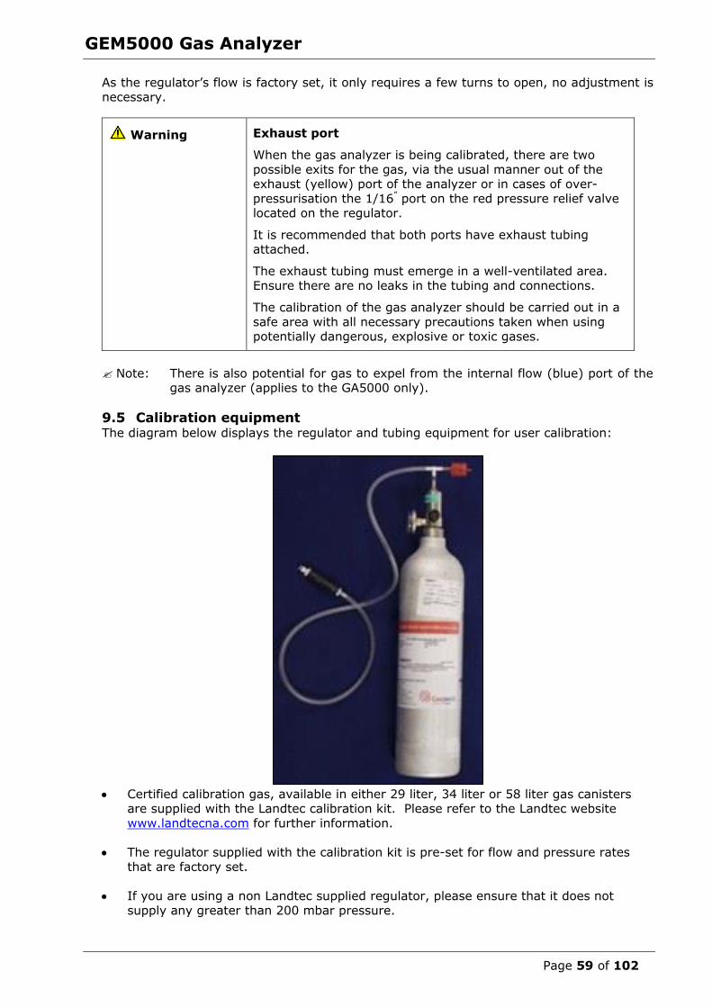
GEM5000 Gas Analyzer
Page 59 of 102
As the regulator’s flow is factory set, it only requires a few turns to open, no adjustment is
necessary.
Warning Exhaust port
When the gas analyzer is being calibrated, there are two
possible exits for the gas, via the usual manner out of the exhaust (yellow) port of the analyzer or in cases of over-
pressurisation the 1/16” port on the red pressure relief valve located on the regulator.
It is recommended that both ports have exhaust tubing attached.
The exhaust tubing must emerge in a well-ventilated area. Ensure there are no leaks in the tubing and connections.
The calibration of the gas analyzer should be carried out in a
safe area with all necessary precautions taken when using potentially dangerous, explosive or toxic gases.
Note: There is also potential for gas to expel from the internal flow (blue) port of the gas analyzer (applies to the GA5000 only).
9.5 Calibration equipment The diagram below displays the regulator and tubing equipment for user calibration:
Certified calibration gas, available in either 29 liter, 34 liter or 58 liter gas canisters
are supplied with the Landtec calibration kit. Please refer to the Landtec website
www.landtecna.com for further information.
The regulator supplied with the calibration kit is pre-set for flow and pressure rates
that are factory set.
If you are using a non Landtec supplied regulator, please ensure that it does not supply any greater than 200 mbar pressure.
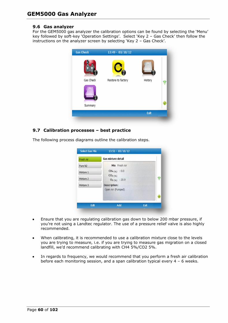
GEM5000 Gas Analyzer
Page 60 of 102
9.6 Gas analyzer For the GEM5000 gas analyzer the calibration options can be found by selecting the ‘Menu’
key followed by soft-key ‘Operation Settings’. Select ‘Key 2 – Gas Check’ then follow the instructions on the analyzer screen by selecting ‘Key 2 – Gas Check’.
9.7 Calibration processes – best practice
The following process diagrams outline the calibration steps.
Ensure that you are regulating calibration gas down to below 200 mbar pressure, if
you’re not using a Landtec regulator. The use of a pressure relief valve is also highly recommended.
When calibrating, it is recommended to use a calibration mixture close to the levels
you are trying to measure, i.e. if you are trying to measure gas migration on a closed
landfill, we’d recommend calibrating with CH4 5%/CO2 5%.
In regards to frequency, we would recommend that you perform a fresh air calibration before each monitoring session, and a span calibration typical every 4 – 6 weeks.
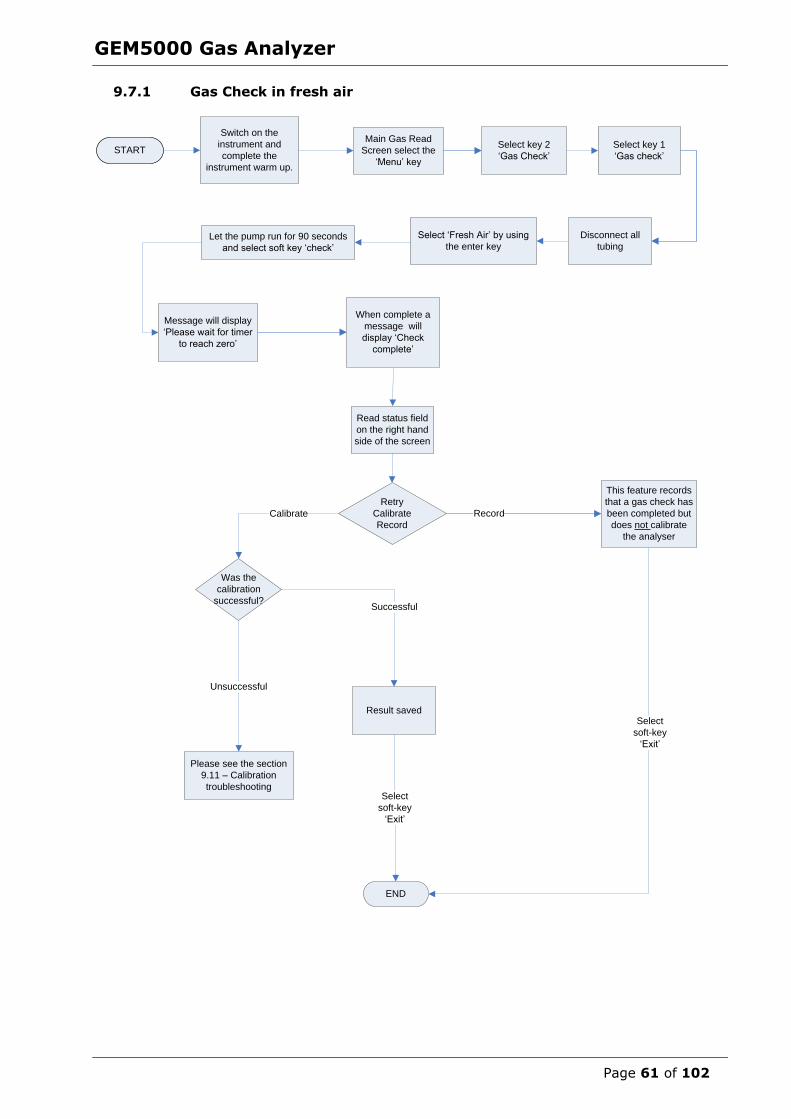
GEM5000 Gas Analyzer
Page 61 of 102
9.7.1 Gas Check in fresh air
START
Switch on the
instrument and
complete the
instrument warm up.
Main Gas Read
Screen select the
‘Menu’ key
Select key 2
‘Gas Check’
Select key 1
‘Gas check’
Message will display
‘Please wait for timer
to reach zero’
When complete a
message will
display ‘Check
complete’
Read status field
on the right hand
side of the screen
Retry
Calibrate
Record
Result saved
END
Record
Select
soft-key
‘Exit’
Calibrate
Select ‘Fresh Air’ by using
the enter key
This feature records
that a gas check has
been completed but
does not calibrate
the analyser
Please see the section
9.11 – Calibration
troubleshooting
Disconnect all
tubingLet the pump run for 90 seconds
and select soft key ‘check’
Was the
calibration
successful?Successful
Unsuccessful
Select
soft-key
‘Exit’

GEM5000 Gas Analyzer
Page 62 of 102
9.7.2 Calibration – mixtures 1, 2, & 3
START
Switch on the
instrument and
complete the
instrument warm up.
Main Gas Read
Screen select the
‘Menu’ key
Select key 1
“Gas check”
Connect the flow
regulator to the
white port on the
analyser
Flow certified gas
mixture using the
gas regulator
supplied
Wait for the readings
to stabilise. Wait for
the analyser to
check spans for
approx. 1 minute.
Message will
display ‘Please
wait for timer to
reach zero’
When complete a
message will
display ‘Check
complete’
Read status field
in the right hand
corner of the
screen
Read status field
in the right hand
corner of the
screen
Retry
Calibrate
Record
END
Select
soft-key
‘Check’
RecordCalibrate
Successful
Select correct gas mixture:
1, 2, or 3, or add User-
selectable gas mixture
Press
‘Enter’
to confirm
Gas mixture
This feature records
that a gas check has
been completed but
does not calibrate the
analyser
Please see section
9.11 – Calibration
troubleshooting
Select
soft-key
‘Exit’
Unsuccessful
Select key 2
‘Gas check ’
Was the
calibration
successful?
Select
soft-key
‘Exit’

GEM5000 Gas Analyzer
Page 63 of 102
9.8 Restore to factory settings
This option will reset the gas analyzer to all of its factory programmed calibration settings and will clear ALL the user defined calibration points. It will not affect or remove ID’s or
readings from the analyzer.
1) Select ‘Key 2 - Restore to factory’ followed by the soft-key ‘Confirm’ or ‘Cancel’.
2) A validation message is displayed ‘Reset user calibration?’ Press the soft-key ‘Confirm’
to continue with the factory settings or soft-key ‘Cancel’ to cancel the operation and return to the Gas Check menu.
9.9 Calibration history The GEM5000 gas analyzer logs user calibrations in ‘History’ application. This can be used as an aid to ensuring that gas measurements are valid and accurate. Both good and failed
calibration results are recorded for each channel calibrated.
1) Select ‘Key 3 – History’.
2) The operator may view the calibration data stored. Use the soft-key ‘Filter’ to add a sort filter to the history enquiry.
9.10 Calibration summary The GEM5000 gas analyzer has the facility to log the history of user calibrations.
1) Select ‘Key 4 – Summary’.
2) The operator may view the calibration data history stored by ID, technician, timestamp, type and calibration result. Use the soft-key ‘Exit’ to exit and return to the
‘Gas Check’ menu.
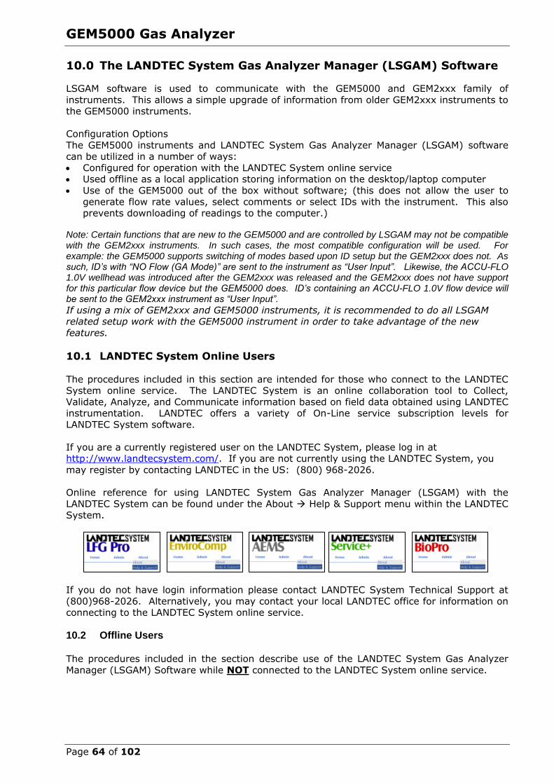
GEM5000 Gas Analyzer
Page 64 of 102
10.0 The LANDTEC System Gas Analyzer Manager (LSGAM) Software
LSGAM software is used to communicate with the GEM5000 and GEM2xxx family of
instruments. This allows a simple upgrade of information from older GEM2xxx instruments to the GEM5000 instruments.
Configuration Options
The GEM5000 instruments and LANDTEC System Gas Analyzer Manager (LSGAM) software can be utilized in a number of ways:
Configured for operation with the LANDTEC System online service Used offline as a local application storing information on the desktop/laptop computer
Use of the GEM5000 out of the box without software; (this does not allow the user to
generate flow rate values, select comments or select IDs with the instrument. This also prevents downloading of readings to the computer.)
Note: Certain functions that are new to the GEM5000 and are controlled by LSGAM may not be compatible with the GEM2xxx instruments. In such cases, the most compatible configuration will be used. For example: the GEM5000 supports switching of modes based upon ID setup but the GEM2xxx does not. As such, ID’s with “NO Flow (GA Mode)” are sent to the instrument as “User Input”. Likewise, the ACCU-FLO 1.0V wellhead was introduced after the GEM2xxx was released and the GEM2xxx does not have support for this particular flow device but the GEM5000 does. ID’s containing an ACCU-FLO 1.0V flow device will be sent to the GEM2xxx instrument as “User Input”.
If using a mix of GEM2xxx and GEM5000 instruments, it is recommended to do all LSGAM related setup work with the GEM5000 instrument in order to take advantage of the new
features.
10.1 LANDTEC System Online Users
The procedures included in this section are intended for those who connect to the LANDTEC System online service. The LANDTEC System is an online collaboration tool to Collect,
Validate, Analyze, and Communicate information based on field data obtained using LANDTEC instrumentation. LANDTEC offers a variety of On-Line service subscription levels for
LANDTEC System software.
If you are a currently registered user on the LANDTEC System, please log in at http://www.landtecsystem.com/. If you are not currently using the LANDTEC System, you
may register by contacting LANDTEC in the US: (800) 968-2026.
Online reference for using LANDTEC System Gas Analyzer Manager (LSGAM) with the
LANDTEC System can be found under the About Help & Support menu within the LANDTEC System.
If you do not have login information please contact LANDTEC System Technical Support at
(800)968-2026. Alternatively, you may contact your local LANDTEC office for information on connecting to the LANDTEC System online service.
10.2 Offline Users The procedures included in the section describe use of the LANDTEC System Gas Analyzer
Manager (LSGAM) Software while NOT connected to the LANDTEC System online service.
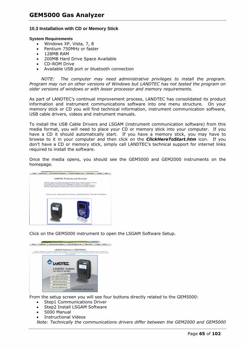
GEM5000 Gas Analyzer
Page 65 of 102
10.3 Installation with CD or Memory Stick System Requirements
Windows XP, Vista, 7, 8 Pentium 750MHz or faster
128MB RAM 200MB Hard Drive Space Available
CD-ROM Drive Available USB port or bluetooth connection
NOTE: The computer may need administrative privileges to install the program. Program may run on other versions of Windows but LANDTEC has not tested the program on
older versions of windows or with lesser processor and memory requirements.
As part of LANDTEC’s continual improvement process, LANDTEC has consolidated its product information and instrument communications software into one menu structure. On your
memory stick or CD you will find technical information, instrument communication software, USB cable drivers, videos and instrument manuals.
To install the USB Cable Drivers and LSGAM (instrument communication software) from this media format, you will need to place your CD or memory stick into your computer. If you
have a CD it should automatically start. If you have a memory stick, you may have to browse to it in your computer and then click on the ClickHereToStart.htm icon. If you
don’t have a CD or memory stick, simply call LANDTEC’s technical support for internet links required to install the software.
Once the media opens, you should see the GEM5000 and GEM2000 instruments on the
homepage.
Click on the GEM5000 instrument to open the LSGAM Software Setup.
From the setup screen you will see four buttons directly related to the GEM5000:
Step1 Communications Driver
Step2 Install LSGAM Software
5000 Manual Instructional Videos
Note: Technically the communications drivers differ between the GEM2000 and GEM5000

GEM5000 Gas Analyzer
Page 66 of 102
instruments, however, the driver package included with the 5000 instruments shipping
after Nov 1, 2012 include drivers for both the GEM5000 and GEM-2000 instruments. The LSGAM software for the GEM5000 is backwards compatible for the GEM2000 instruments.
The LSGAM software will automatically update if an internet connection is available when the software starts. This software has been tested with Windows XP and Windows 7.
Should you have any difficulties, please don’t hesitate to contact us. Our Software
support group can be reached at (800) 968-2026 or [email protected] The instrument communicates to the computer by means of a USB cable or by bluetooth.
The USB cable requires drivers to be installed prior to use on the computer. From the CD (or USB memory stick) choose the first option titled “Step 1”. A Bluetooth connection
requires the instrument to be paired to the computer. Refer to the section “Configuring
Communications” for more details.
The Java programming is an import part of this software and will be loaded with the installation. If you have internet access, it is recommended to update your java to the
latest version by going to http://www.java.com/en then clicking the button for the Free Java download. Once at the Java downloads you’ll see links to download the latest
version of Java for your computer.
The Java icon, shown below, will be in the task tray at the bottom of your computer
screen where your time is shown. There will also be a GAM log icon, shown below, that
will be created on your desk top during installation.
10.4 Start Up
Once the USB cable drivers are installed and you’ve checked for the latest Java Runtime from
the www.java.com/en website, click on “Step 2 — Install LSGAM”. LSGAM will install placing an Icon on your desktop and a new Start Menu Group named LANDTEC.
Starting LSGAM can be easily done by doing one of the following:
Double-Click on the Desktop icon. OR - go to;
Start All Programs LANDTEC LANDTEC System Gas Analyzer Manager
The software will start.
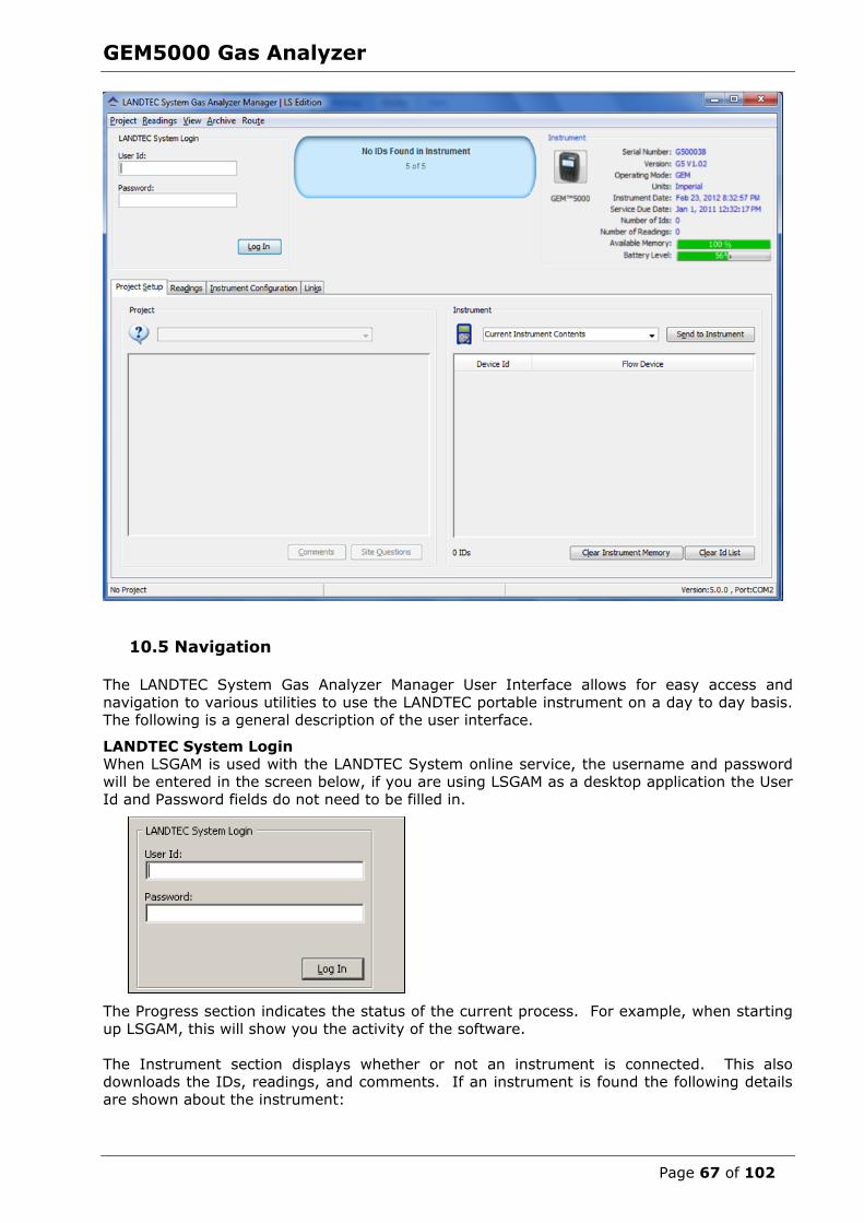
GEM5000 Gas Analyzer
Page 67 of 102
10.5 Navigation
The LANDTEC System Gas Analyzer Manager User Interface allows for easy access and
navigation to various utilities to use the LANDTEC portable instrument on a day to day basis. The following is a general description of the user interface.
LANDTEC System Login When LSGAM is used with the LANDTEC System online service, the username and password
will be entered in the screen below, if you are using LSGAM as a desktop application the User Id and Password fields do not need to be filled in.
The Progress section indicates the status of the current process. For example, when starting
up LSGAM, this will show you the activity of the software.
The Instrument section displays whether or not an instrument is connected. This also downloads the IDs, readings, and comments. If an instrument is found the following details
are shown about the instrument:

GEM5000 Gas Analyzer
Page 68 of 102
10.6 Connecting to the Instrument
Connect the GEM5000 to your computer with either the USB cable or a Bluetooth
connection. In the event you instrument has difficulty connecting, refer to Appendix—Configuring Communication Connections for more information setting up
and testing USB Serial communications and Bluetooth Serial communications.
The Instrument must be powered ON and in the Gas Reading screen Launch the LSGAM software by clicking on the icon on your desktop
This is the first screen you will see when starting the program.
or
Once the software is installed on your computer with an internet connection this instrument communications program has Auto application updates. This enables you to always have the most current version of the instrument communications LSGAM. If an update to LSGAM is available, you will be prompted to install the update.

GEM5000 Gas Analyzer
Page 69 of 102
Click on OK this will return you to the desktop and you will then need to click on the
LSGAM shortcut again.
The GEM5000 must be connected to computer and turned ON. It must also be in the Gas
Reading screen. The LSGAM software will automatically download any information in the instrument including readings, comments and IDs.
Note: Connection of instrument to computer should not be performed in a hazardous area.
A new instrument containing no information will display only the instrument information:
Serial Number, Version, Operating Mode, Instrument Date, Service Due Date, Number of IDs, Number of Readings, Available Memory, and Battery Level.
10.7 Create a Project/Select a Project
Projects are a collection of Device IDs and their associated reading history. A project can be created using LSGAM to contain a group of sequenced IDs and chronological history of
instrument readings.
To create a Project, click on the Project menu and select New Project.

GEM5000 Gas Analyzer
Page 70 of 102
Upon selecting New Project… you will be prompted to enter a Project Name and select from
one of three options.
Create a New Empty Project This option creates a blank project where you configure all IDs and Comments. Alternately
ID’s can be loaded from a file using the DataField CS version 3.4 ID file format.
Create a New Project with comments and site questions from a Current Project Selecting this option allows the user to create a new project that will have the same
Comments and Site Questions as an existing project.
Create a New Project from the data in a GEM instrument
This option will create a New Project and automatically associate the IDs, Comments, and Site Questions that exist in the connected portable instrument.
10.7.1 ID Set Up
An ID represents a physical sampling point in the field. An ID can be allocated to field components such as extraction wellheads, gas transmission lines, or passive monitoring
probes. LSGAM allows users to configure an ID for each sampling point in order to obtain
accurate readings with LANDTEC portable instrumentation
IDs are created, modified, and removed from the Project Setup tab in the software.
10.7.2 Creating Comments
Comments should be setup prior to creating new IDs. The user can define Comments that
can be associated with a reading in the portable instrument.
If you selected Create a New Project, when creating your project, you will need to click on the
Create Comments button. Comments can be entered in this setup screen or loaded from a text file and will be displayed in the user interface. Comments can be 64 characters in
length. “Notepad” or another text editor can be used to create a file containing one comment per line up to 64 comments in total.
Note: It is extremely important to NOT include any punctuation other than dashes or
underscores when setting up a comments file in notepad. Commas and Quotation marks are used by programs for determining where data begins and ends. Using characters other than
underscores and dashes and cause unpredictable results within the data when downloaded
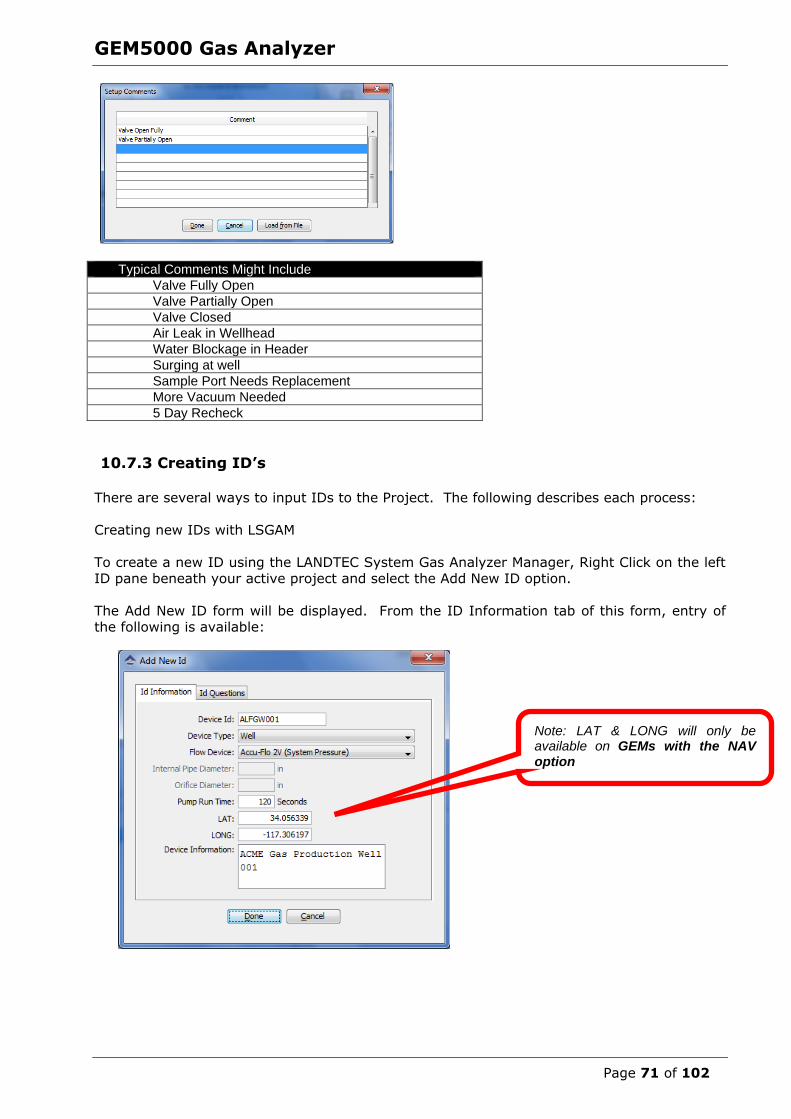
GEM5000 Gas Analyzer
Page 71 of 102
Typical Comments Might Include
Valve Fully Open
Valve Partially Open
Valve Closed
Air Leak in Wellhead
Water Blockage in Header
Surging at well
Sample Port Needs Replacement
More Vacuum Needed
5 Day Recheck
10.7.3 Creating ID’s
There are several ways to input IDs to the Project. The following describes each process:
Creating new IDs with LSGAM
To create a new ID using the LANDTEC System Gas Analyzer Manager, Right Click on the left
ID pane beneath your active project and select the Add New ID option.
The Add New ID form will be displayed. From the ID Information tab of this form, entry of the following is available:
Note: LAT & LONG will only be available on GEMs with the NAV option
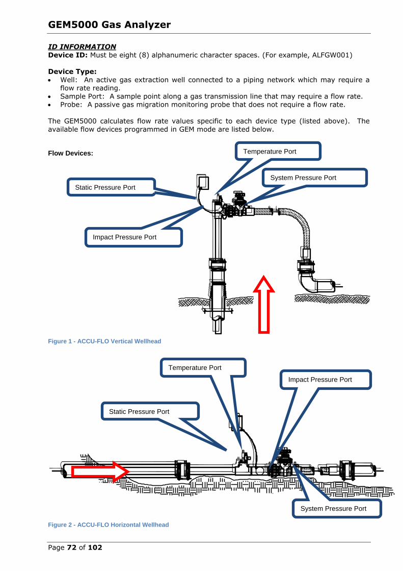
GEM5000 Gas Analyzer
Page 72 of 102
ID INFORMATION
Device ID: Must be eight (8) alphanumeric character spaces. (For example, ALFGW001)
Device Type:
Well: An active gas extraction well connected to a piping network which may require a flow rate reading.
Sample Port: A sample point along a gas transmission line that may require a flow rate. Probe: A passive gas migration monitoring probe that does not require a flow rate.
The GEM5000 calculates flow rate values specific to each device type (listed above). The
available flow devices programmed in GEM mode are listed below.
Flow Devices:
Figure 1 - ACCU-FLO Vertical Wellhead
Figure 2 - ACCU-FLO Horizontal Wellhead
Static Pressure Port
Impact Pressure Port
Temperature Port
System Pressure Port
Static Pressure Port
Temperature Port
System Pressure Port
Impact Pressure Port

GEM5000 Gas Analyzer
Page 73 of 102
Figure 3 - Pitot Tube
Figure 4 - Orifice Plate (WellSide) Orifice Plate
Impact/Total Pressure Port
Static Pressure Port
Impact Pressure/ “Low Pressure”
Static Pressure / “High Pressure”
Impact Pressure/ “High Pressure”
Static Pressure / “Low Pressure”
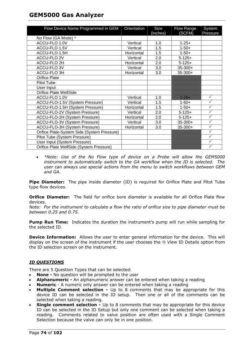
GEM5000 Gas Analyzer
Page 74 of 102
Flow Device Name Programmed in GEM Orientation Size (Inches)
Flow Range (SCFM)
System Pressure
No Flow (GA Mode) *
ACCU-FLO 1.0V Vertical 1.0 1-25+
ACCU-FLO 1.5V Vertical 1.5 1-50+
ACCU-FLO 1.5H Horizontal 1.5 1-50+
ACCU-FLO 2V Vertical 2.0 5-125+
ACCU-FLO 2H Horizontal 2.0 5-125+
ACCU-FLO 3V Vertical 3.0 35-300+
ACCU-FLO 3H Horizontal 3.0 35-300+
Orifice Plate
Pitot Tube
User Input
Orifice Plate WellSide
ACCU-FLO 1.0V Vertical 1.0 1-25+
ACCU-FLO-1.5V (System Pressure) Vertical 1.5 1-50+
ACCU-FLO-1.5H (System Pressure) Horizontal 1.5 1-50+
ACCU-FLO-2V (System Pressure) Vertical 2.0 5-125+
ACCU-FLO-2H (System Pressure) Horizontal 2.0 5-125+
ACCU-FLO-3V (System Pressure) Vertical 3.0 35-300+
ACCU-FLO-3H (System Pressure) Horizontal 3.0 35-300+
Orifice Plate-System Side (System Pressure)
Pitot Tube (System Pressure)
User Input (System Pressure)
Orifice Plate WellSide (System Pressure)
*Note: Use of the No Flow type of device on a Probe will allow the GEM5000 instrument to automatically switch to the GA workflow when the ID is selected. The
user can always use special actions from the menu to switch workflows between GEM and GA.
Pipe Diameter: The pipe inside diameter (ID) is required for Orifice Plate and Pitot Tube
type flow devices.
Orifice Diameter: The field for orifice bore diameter is available for all Orifice Plate flow
devices. Note: For the instrument to calculate a flow the ratio of orifice size to pipe diameter must be
between 0.25 and 0.75.
Pump Run Time: Indicates the duration the instrument’s pump will run while sampling for the selected ID.
Device Information: Allows the user to enter general information for the device. This will
display on the screen of the instrument if the user chooses the View ID Details option from
the ID selection screen on the instrument.
ID QUESTIONS
There are 5 Question Types that can be selected:
None - No question will be prompted to the user Alphanumeric - An alphanumeric answer can be entered when taking a reading
Numeric - A numeric only answer can be entered when taking a reading Multiple Comment selection - Up to 8 comments that may be appropriate for this
device ID can be selected in the ID setup. Then one or all of the comments can be selected when taking a reading.
Single comment selection - Up to 8 comments that may be appropriate for this device ID can be selected in the ID Setup but only one comment can be selected when taking a
reading. Comments related to valve position are often used with a Single Comment
Selection because the valve can only be in one position.

GEM5000 Gas Analyzer
Page 75 of 102
10.7.4 Importing Data Field CS ID’s
If you have existing ID files from DataField CS v3.4.x, these files can be imported by LSGAM. To begin this operation select the Import IDs… option from the Project menu.
Select an ID file generated by DataField CS v3.4.x.
10.7.5 Creating a New Project (ID’s already in instrument) To create a Project based on the information in the instrument, select Create a new project from the data in my instrument.

GEM5000 Gas Analyzer
Page 76 of 102
Note: When using the Creating a new project from the data in the instrument option,
only IDs NOT associated with other projects will be created into the new project.
Creating a Device ID that does not measure flow Example- Probe or Sample Port
If there is no flow device you can choose the “No Flow (GA Mode)” option. Alternatively, you can also choose User Input. When choosing the User Input option you will need to enter the
appropriate pipe inside diameter. A pump run-time must be specified in with either type of flow device.
Figure 5—Probe Definition using "No Flow" option
Figure 6—Probe Definition using "User Input"
10.7.6 Creating Site Questions
Site questions are setup in the same manner as ID questions however unlike ID questions,
the answers for Site questions will apply to all subsequent readings until the site question is updated. A total of 5 site questions can be sent to your instrument. These must be updated
each time you use the GEM. This is done by going to the Menu selection on the instrument
and choosing [Update Site Data]
The options for questions are Alphanumeric – Numeric – Multiple or Single comment selection.
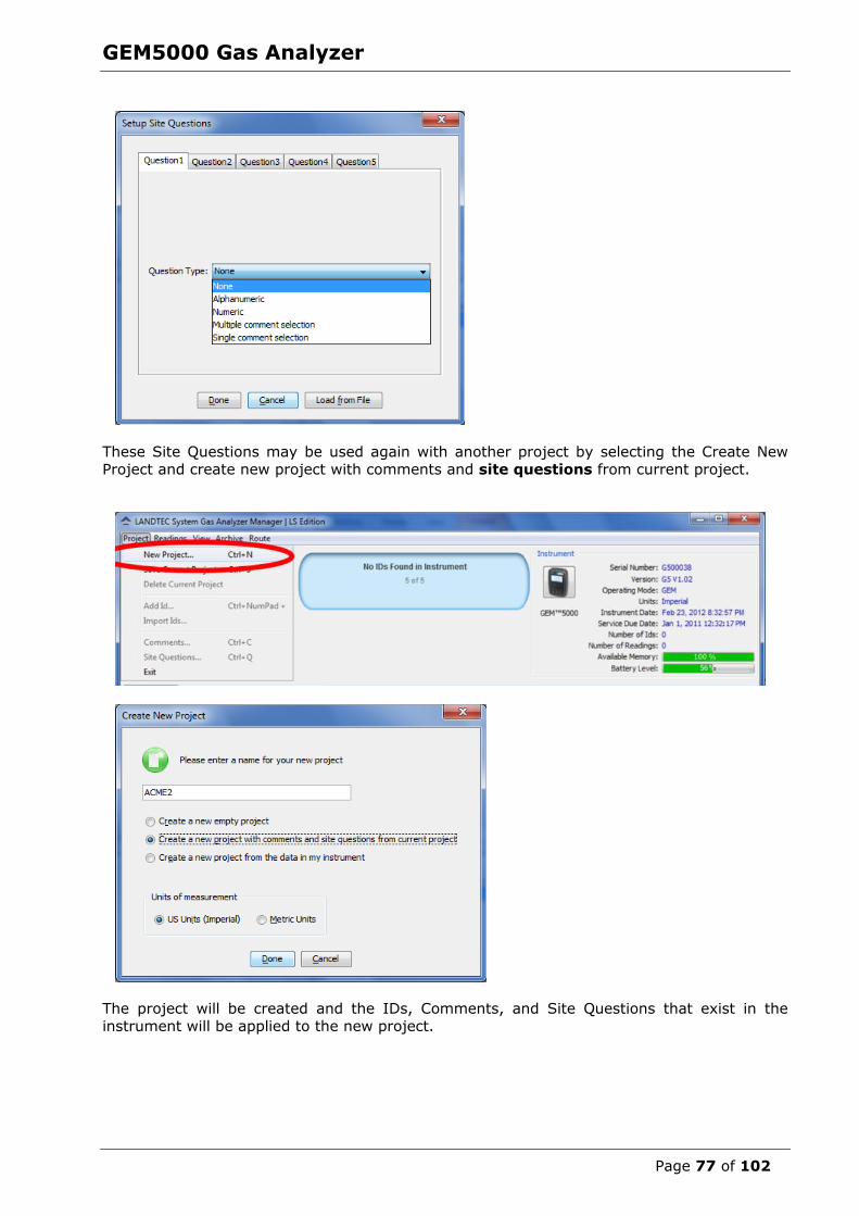
GEM5000 Gas Analyzer
Page 77 of 102
These Site Questions may be used again with another project by selecting the Create New
Project and create new project with comments and site questions from current project.
The project will be created and the IDs, Comments, and Site Questions that exist in the
instrument will be applied to the new project.
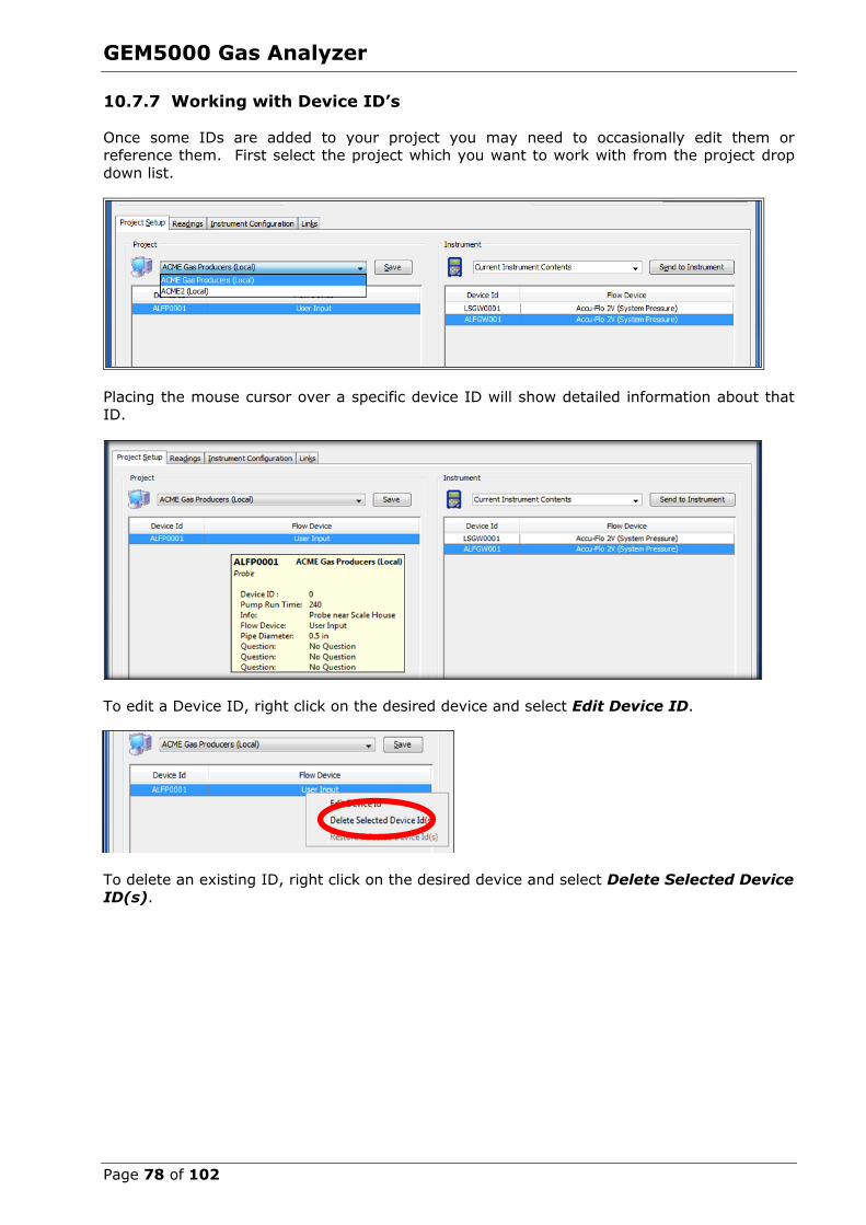
GEM5000 Gas Analyzer
Page 78 of 102
10.7.7 Working with Device ID’s
Once some IDs are added to your project you may need to occasionally edit them or reference them. First select the project which you want to work with from the project drop
down list.
Placing the mouse cursor over a specific device ID will show detailed information about that
ID.
To edit a Device ID, right click on the desired device and select Edit Device ID.
To delete an existing ID, right click on the desired device and select Delete Selected Device ID(s).
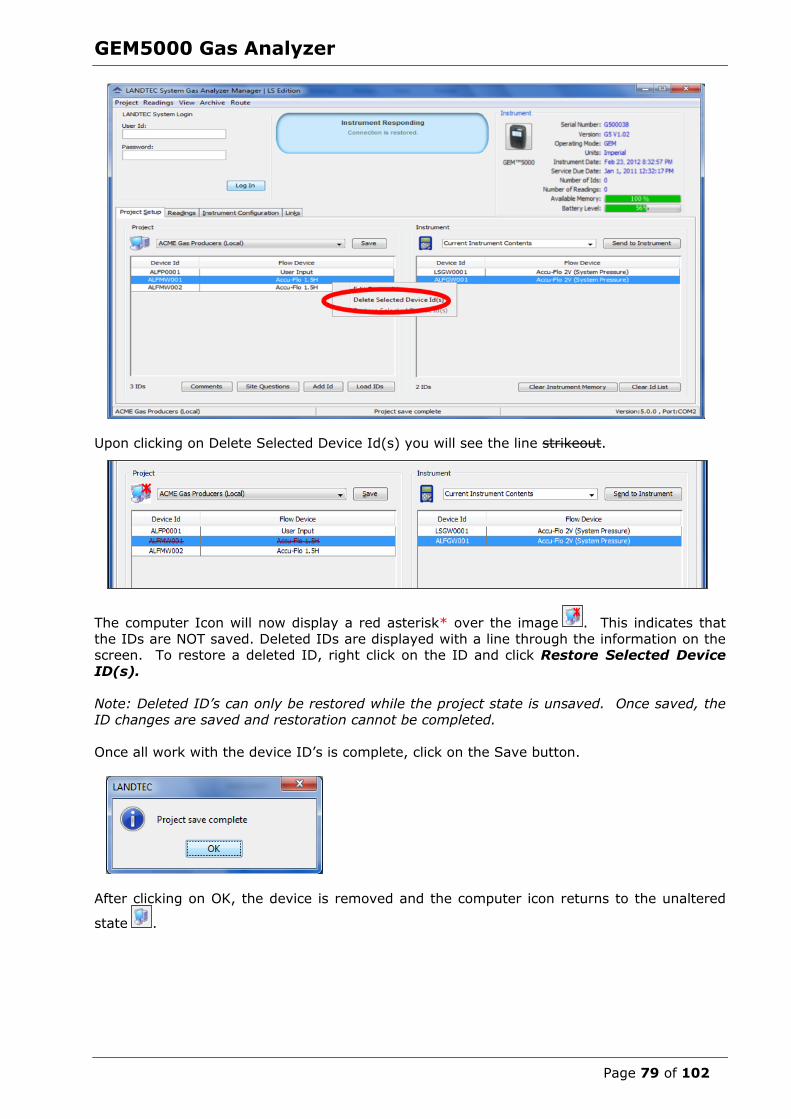
GEM5000 Gas Analyzer
Page 79 of 102
Upon clicking on Delete Selected Device Id(s) you will see the line strikeout.
The computer Icon will now display a red asterisk* over the image . This indicates that
the IDs are NOT saved. Deleted IDs are displayed with a line through the information on the screen. To restore a deleted ID, right click on the ID and click Restore Selected Device
ID(s).
Note: Deleted ID’s can only be restored while the project state is unsaved. Once saved, the
ID changes are saved and restoration cannot be completed.
Once all work with the device ID’s is complete, click on the Save button.
After clicking on OK, the device is removed and the computer icon returns to the unaltered
state .

GEM5000 Gas Analyzer
Page 80 of 102
10.7.8 Sending ID’s to the Instrument
Once IDs have been created in the project, they must be uploaded to the instrument. To
perform this operation, select the desired IDs from the left hand table under the Project name (computer side), left click and hold while dragging the IDs to the right hand table and
release the mouse button. This is action is known as a “Drag & Drop”.
Three basic methods of selecting IDs exist. Select Specific ID(s)
Select a Range of IDs
Select All IDs
Specific IDs
To Select Specific IDs from the List, place the mouse arrow at the edge of the first cell
and hold down the left Ctrl key. Now click the next ID cell that you wish to select. Repeat this
as many times as necessary.
Selected IDs (shown as Highlighted). Arrow depicts "Drag & Drop" action after selection.
Now “Drag & Drop” the IDs from the left (computer window) to the right (instrument
window). During the “Drag &Drop” process, the arrow will change to .
The selected IDs ALFP001, ALFMW002, and ALFMW004 now appear on the Right (Instrument) side. At this point the IDs are on the Instrument side but have NOT been sent to the
instrument. The instrument with the red asterisk * indicates this unsent ID state.
Click on the Send to Instrument button to send these IDs to the instrument.
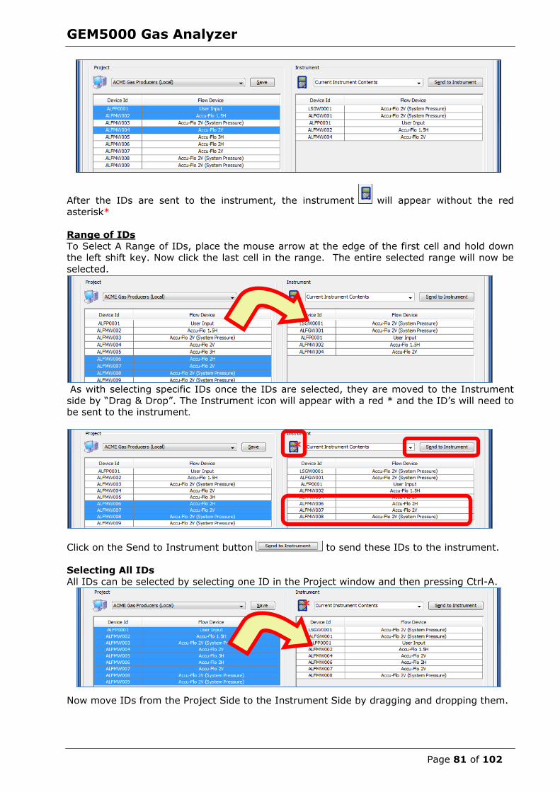
GEM5000 Gas Analyzer
Page 81 of 102
After the IDs are sent to the instrument, the instrument will appear without the red
asterisk*
Range of IDs
To Select A Range of IDs, place the mouse arrow at the edge of the first cell and hold down the left shift key. Now click the last cell in the range. The entire selected range will now be
selected.
As with selecting specific IDs once the IDs are selected, they are moved to the Instrument
side by “Drag & Drop”. The Instrument icon will appear with a red * and the ID’s will need to be sent to the instrument.
Click on the Send to Instrument button to send these IDs to the instrument.
Selecting All IDs
All IDs can be selected by selecting one ID in the Project window and then pressing Ctrl-A.
Now move IDs from the Project Side to the Instrument Side by dragging and dropping them.

GEM5000 Gas Analyzer
Page 82 of 102
If you are dragging and dropping an ID that is already on the instrument side, you will be
prompted with the above message. Answer Yes to update the IDs on the instrument side from those on the computer side. Answer No to ignore IDs that are already in the
instrument. Answer Cancel to cancel the action without sending ID’s to the instrument side.
Click on the Send to Instrument button to send these IDs to the instrument.
10.7.9 Clearing ID’s or Deleting a Project
In current instrument contents when selecting the Clear ID List option, lines will be drawn through the IDs.
You then need to select Send to Instrument. This will clear all IDs from the instrument.

GEM5000 Gas Analyzer
Page 83 of 102
You may also delete one ID from a list by highlighting the ID RIGHT CLICK with your mouse
and select the Delete Selected Device option. If you have selected the wrong ID and deleted then you may select the Restore option to return the ID to the list.
Upon selecting Delete Selected Device Id(s) you will see a strikeout line appear through the
ID
Click on the Send to Instrument button to send the ID corrections to the
instrument.
The instrument contents will now be updated and the ALFMW004 ID no longer shows in the instrument side of the list.
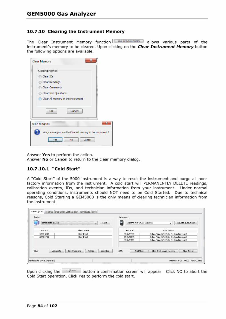
GEM5000 Gas Analyzer
Page 84 of 102
10.7.10 Clearing the Instrument Memory
The Clear Instrument Memory function allows various parts of the
instrument’s memory to be cleared. Upon clicking on the Clear Instrument Memory button the following options are available.
Answer Yes to perform the action.
Answer No or Cancel to return to the clear memory dialog.
10.7.10.1 “Cold Start”
A “Cold Start” of the 5000 instrument is a way to reset the instrument and purge all non-
factory information from the instrument. A cold start will PERMANENTLY DELETE readings, calibration events, IDs, and technician information from your instrument. Under normal
operating conditions, instruments should NOT need to be Cold Started. Due to technical
reasons, Cold Starting a GEM5000 is the only means of clearing technician information from the instrument.
Upon clicking the button a confirmation screen will appear. Click NO to abort the
Cold Start operation, Click Yes to perform the cold start.
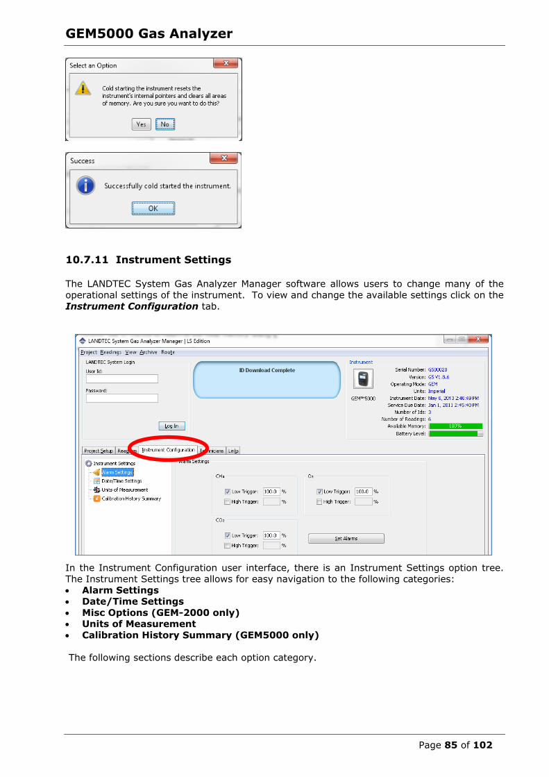
GEM5000 Gas Analyzer
Page 85 of 102
10.7.11 Instrument Settings
The LANDTEC System Gas Analyzer Manager software allows users to change many of the
operational settings of the instrument. To view and change the available settings click on the
Instrument Configuration tab.
In the Instrument Configuration user interface, there is an Instrument Settings option tree. The Instrument Settings tree allows for easy navigation to the following categories:
Alarm Settings Date/Time Settings
Misc Options (GEM-2000 only) Units of Measurement
Calibration History Summary (GEM5000 only)
The following sections describe each option category.

GEM5000 Gas Analyzer
Page 86 of 102
10.7.12 Alarm Settings
The Alarm Settings options control the activation and deactivation of the audible alarms in the instrument. Audible alarms can be configured for CH4, CO2, and O2 parameters
(additional gases present on plus model instrument). Each parameter can be configured with a Low Trigger and/or High Trigger for the alarm. To activate any specific alarm, click and
place a checkmark in the desired box. This will activate the entry field to place the value.
The values must be 0 – 100 percent. When alarms are set, the instrument will highlight the composition component in orange on the 5000 instrument on the 2000 instrument it will beep
and flash the parameter on the screen if an alarm threshold is surpassed when taking a gas reading. Refer to the section titled “Set Alarms” for additional options that are available for
setting alarms directly on the 5000’s instrument.
Figure 7—Alarm Highlighting Example
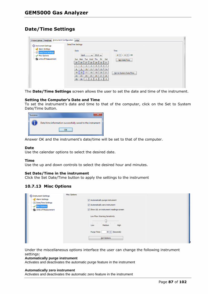
GEM5000 Gas Analyzer
Page 87 of 102
Date/Time Settings
The Date/Time Settings screen allows the user to set the date and time of the instrument.
Setting the Computer’s Date and Time To set the instrument’s date and time to that of the computer, click on the Set to System
Date/Time button.
Answer OK and the instrument’s date/time will be set to that of the computer.
Date Use the calendar options to select the desired date.
Time
Use the up and down controls to select the desired hour and minutes.
Set Date/Time in the instrument Click the Set Date/Time button to apply the settings to the instrument
10.7.13 Misc Options
Under the miscellaneous options interface the user can change the following instrument
settings: Automatically purge instrument Activates and deactivates the automatic purge feature in the instrument Automatically zero instrument Activates and deactivates the automatic zero feature in the instrument

GEM5000 Gas Analyzer
Page 88 of 102
Low Flow Warning Specifies the point at which the instrument will “Flow Fail”. If the instrument detects that it is not able to extract the appropriate gas flow for analysis the word “Flow” will flash in the upper left part of the screen where the pump timer is normally shown. If flow does not increase the pump will automatically be stopped. Adjusting the setting to “Low” will allow the pump to run with less flow going through the instrument. This may help avoid flow fail conditions when sampling from high vacuum systems. Purge Time Specifies the duration the pump will run when activated by the purge feature of the instrument.
10.7.14 Units of Measurement
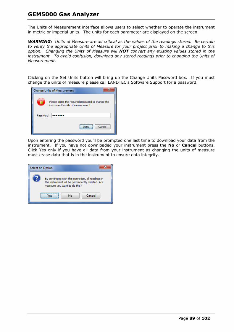
GEM5000 Gas Analyzer
Page 89 of 102
The Units of Measurement interface allows users to select whether to operate the instrument
in metric or imperial units. The units for each parameter are displayed on the screen.
WARNING: Units of Measure are as critical as the values of the readings stored. Be certain
to verify the appropriate Units of Measure for your project prior to making a change to this option. Changing the Units of Measure will NOT convert any existing values stored in the
instrument. To avoid confusion, download any stored readings prior to changing the Units of Measurement.
Clicking on the Set Units button will bring up the Change Units Password box. If you must change the units of measure please call LANDTEC’s Software Support for a password.
Upon entering the password you’ll be prompted one last time to download your data from the
instrument. If you have not downloaded your instrument press the No or Cancel buttons. Click Yes only if you have all data from your instrument as changing the units of measure
must erase data that is in the instrument to ensure data integrity.

GEM5000 Gas Analyzer
Page 90 of 102
Calibration History Summary
The Calibration History Summary allows you to view the calibrations, Save the Calibration History and Clear the Calibration History.
Viewing the calibration history can be done simply by clicking on “Calibration History
Summary” option within the Instrument Configuration tab
Saving the calibration history to file can be accomplished by clicking on the button. Upon clicking the Save button. You will be prompted for a directory location and file
name for storing file.
The directory location varies depending upon your operating system. In Windows 7 & 8 it is
in C:\ProgramData\LANDTEC\LSGAM\EventLogs
On Windows XP the directory defaults to
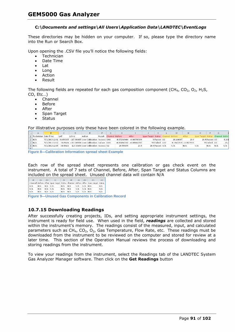
GEM5000 Gas Analyzer
Page 91 of 102
C:\Documents and settings\All Users\Application Data\LANDTEC\EventLogs
These directories may be hidden on your computer. If so, please type the directory name
into the Run or Search Box.
Upon opening the .CSV file you’ll notice the following fields:
Technician Date Time
Lat Long
Action Result
The following fields are repeated for each gas composition component (CH4, CO2, O2, H2S, CO, Etc…)
Channel Before
After Span Target
Status
For illistrative purposes only these have been colored in the following example.
Figure 8—Calibration Information spread sheet Example
Each row of the spread sheet represents one calibration or gas check event on the
instrument. A total of 7 sets of Channel, Before, After, Span Target and Status Columns are included on the spread sheet. Unused channel data will contain N/A
Figure 9—Unused Gas Components in Calibration Record
10.7.15 Downloading Readings
After successfully creating projects, IDs, and setting appropriate instrument settings, the
instrument is ready for field use. When used in the field, readings are collected and stored
within the instrument’s memory. The readings consist of the measured, input, and calculated parameters such as CH4, CO2, O2, Gas Temperature, Flow Rate, etc. These readings must be
downloaded from the instrument to be reviewed on the computer and stored for review at a later time. This section of the Operation Manual reviews the process of downloading and
storing readings from the instrument.
To view your readings from the instrument, select the Readings tab of the LANDTEC System Gas Analyzer Manager software. Then click on the Get Readings button

GEM5000 Gas Analyzer
Page 92 of 102
When the instrument is initially detected by the LSGAM software, the Get Readings button will activate if there are readings in the instrument to be downloaded.
Readings will be highlighted based upon the following: Online Project: If the readings were taken against an ID belonging to an On-Line
Enterprise System which the download computer is configured for as (REMOTE) the readings will highlight in a green color.
Local Project: If the readings were taken against a project that is setup on the
computer as a local project then they will highlight in a beige color. Unknown Project: IDs in the instrument that do not match any of the Local or
Remote projects on the download computer. This is the result of uploading an instrument with IDs from one computer but downloading on a different computer
without the exact same project configuration(s). Duplicate Reading: This does not imply that the reading was taken twice. Rather it
is an indication that the reading was previously downloaded and exists on the computer in a different readings file.
Placing your mouse over a reading will display additional parameters of the reading. As shown below on the left, clicking on a reading will open a Reading details window and allow
you to click through the readings one-by-one in detail by clicking the Previous and Next buttons.
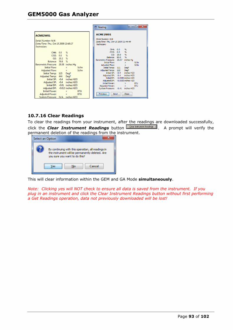
GEM5000 Gas Analyzer
Page 93 of 102
10.7.16 Clear Readings
To clear the readings from your instrument, after the readings are downloaded successfully,
click the Clear Instrument Readings button . A prompt will verify the
permanent deletion of the readings from the instrument.
This will clear information within the GEM and GA Mode simultaneously.
Note: Clicking yes will NOT check to ensure all data is saved from the instrument. If you
plug in an instrument and click the Clear Instrument Readings button without first performing
a Get Readings operation, data not previously downloaded will be lost!

GEM5000 Gas Analyzer
Page 94 of 102
10.7.17 Exporting Readings
To export readings to a file, click the Export Readings button.
This will open the Stamping Information Screen. Stamping information are details that are most often stored with the historical data but not directly stored by the instrument. Detailed
historical Stamping Information can assist when reviewing the data as atmospheric conditions do impact a gas system’s production performance.
Clicking on Done will open the Export Readings to CSV screen.
Note: Depending upon your specific Instrument model you will see additional fields specific to the instrument. For example “NAV” option models have the fields of Latitude, Longitude,
Altitude, Herror, Verror, and HDOP Status that the others models do not have.

GEM5000 Gas Analyzer
Page 95 of 102
This interface provides several options described below.
To add or remove a single reading from export, uncheck the checkbox in the leftmost
column. To add or remove a specific parameter from export, uncheck the corresponding checkbox
across the top. To clear all row checkboxes, click the Clear All Rows button at the bottom of the screen.
After Clearing all Rows you can click the button and it will change to Set all Rows To clear all column selections, click on the Clear All Columns button at the bottom of the
screen. After Clearing All Columns the button will change and you can then choose Set All Columns
To exit the operation without saving, click the Cancel button.
To specify a filename and save the selection to a file, click the Save File button. Clicking this button will open a Save window.
The save file dialog will open and default to the My Documents of the user who is currently
logged in on the computer. Specify a filename and location then click the Save button. The selected readings will be saved in comma separated value (.CSV) format. The .CSV file may
now be opened in another application such as Microsoft Office Excel or Open Office Calc.
11.0 Problem Solving This section outlines various warning and error messages which the operator may receive
during general operation of the instrument. For further assistance please contact Technical Support at (800) 968-2026 or email [email protected]
12.0 Warning and Error display
When switched on, the instrument will perform a pre-determined self-test sequence taking
approximately 15 seconds. During this time many of the instrument’s working parameters and settings are checked.
If any operational parameters are out of specification or the pre-programmed
recommended calibration/service date has passed, errors or warnings may be displayed.
Use the ‘Scroll up’ and ‘Scroll down’ keys to move through the list if required.
Only three warnings/errors can be displayed at any time.
To ascertain if more errors have occurred use ‘Key 8’ – Scroll down’ and ‘Key 2’ - Scroll up’
through the list.
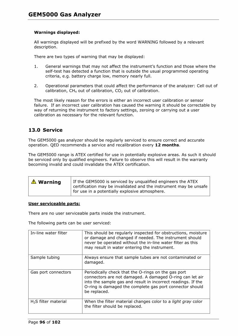
GEM5000 Gas Analyzer
Page 96 of 102
Warnings displayed:
All warnings displayed will be prefixed by the word WARNING followed by a relevant
description.
There are two types of warning that may be displayed:
1. General warnings that may not affect the instrument’s function and those where the self-test has detected a function that is outside the usual programmed operating
criteria, e.g. battery charge low, memory nearly full.
2. Operational parameters that could affect the performance of the analyzer: Cell out of
calibration, CH4 out of calibration, CO2 out of calibration.
The most likely reason for the errors is either an incorrect user calibration or sensor failure. If an incorrect user calibration has caused the warning it should be correctable by
way of returning the instrument to factory settings, zeroing or carrying out a user calibration as necessary for the relevant function.
13.0 Service
The GEM5000 gas analyzer should be regularly serviced to ensure correct and accurate operation. QED recommends a service and recalibration every 12 months.
The GEM5000 range is ATEX certified for use in potentially explosive areas. As such it should
be serviced only by qualified engineers. Failure to observe this will result in the warranty becoming invalid and could invalidate the ATEX certification.
Warning If the GEM5000 is serviced by unqualified engineers the ATEX
certification may be invalidated and the instrument may be unsafe
for use in a potentially explosive atmosphere.
User serviceable parts:
There are no user serviceable parts inside the instrument.
The following parts can be user serviced:
In-line water filter This should be regularly inspected for obstructions, moisture or damage and changed if needed. The instrument should
never be operated without the in-line water filter as this may result in water entering the instrument.
Sample tubing Always ensure that sample tubes are not contaminated or damaged.
Gas port connectors Periodically check that the O-rings on the gas port connectors are not damaged. A damaged O-ring can let air
into the sample gas and result in incorrect readings. If the O-ring is damaged the complete gas port connector should
be replaced.
H2S filter material When the filter material changes color to a light gray color
the filter should be replaced.

GEM5000 Gas Analyzer
Page 97 of 102
14.0 Warranty policy
This instrument is guaranteed, to the original end user purchaser, against defect in materials
and workmanship for a period of 3 years from the date of the shipment to the user.
During this period QED will repair or replace defective parts on an exchange basis.
The decision to repair or replace will be determined by QED.
To maintain this warranty, the purchaser must perform maintenance and calibration as prescribed in the operating manual.
Normal wear and tear, and parts damaged by abuse, misuse, negligence or accidents are specifically excluded from the warranty.
Note: Please contact Technical Support at (800) 968-2026 or email
[email protected] for further information.
GEM5000 Gas Analyzer
Page 98 of 102
15.0 Glossary of terms
5000 series The 5000 series refers to the GA5000, GEM5000
and the Biogas5000 gas analyzers.
Accu-Flo A flow device used to aid accurate flow measurement.
Analyzer error messages Operational errors are prefixed on the analyzer
by the word ERROR followed by an error code.
Refer to the list of standard error codes for
more information.
Analyzer warning Analyzer warnings are prefixed by the word WARNING followed by a relevant description.
There are two types of warning messages displayed; general warnings that may not
necessarily affect the instrument’s function (for example, battery power low) and operational
parameters that could affect the performance of
the analyser (for example, CH4 out of calibration).
Anemometer probe Device for measuring velocity of gas in the pipe.
The GEM5000 analyzer can be set to convert into a flow. See also flow measurement.
ATEX certification The GEM5000 is ATEX certified to zone 1 & 2
areas above ground not in mines.
Auxiliary channel This refers to the channels where external
devices will be connected or displayed.
Backlight The analyser has a built-in backlight for low ambient light conditions. This can be toggled
on/off using the backlight key.
Barometric pressure The atmospheric pressure at the given location.
Borehole Typical location from which a gas sample is
obtained.
Calibration The gas analyzer is carefully calibrated against known standards.
Calibration record The GEM5000 instrument has the facility to log
user calibrations as a validation tool.
CH4 Methane
Chemical cells A method of gas detection that works on the
basis of a chemical reaction with the target gas.
Clean air purge Process used to clear out gas from the sample tube and analyser prior to taking a new reading.
GEM5000 Gas Analyzer
Page 99 of 102
CO Carbon monoxide
CO2
Data logging
Carbon dioxide
Data logging enables the operator to leave the analyzer unattended to take samples at
predetermined intervals for a set period of time
Download Terminology used for the movement of data from the analyzer to the LSGAM application on
the PC.
Dual beam infrared absorption Method of gas detection by measuring how
much infrared is absorbed by the target gas.
Event log Used as an aid to monitoring the use of the analyser. It can also be used as a diagnostic
tool.
The event log can be viewed via LSGAM. It cannot be viewed on the analyzer screen.
Exhaust port The usual manner for the gas to exit the analyzer is via the exhaust port located on the
top side of the analyzer. This port should have an exhaust tube attached.
Exhaust tube Clear plastic tubing used to expel gases from
the exhaust port.
Factory settings Default settings preset at time of manufacture
or service.
Firmware Firmware is the term by which the internal analyzer software is known and is not accessible
by the client. This firmware is updated to the latest version when the analyzer is returned for
servicing.
Flow measurement Flow can be measured by either gas velocity
m/s or volume flow rate m3/hr. This measurement of flow relates to the use of the
anemometer and not the internal flow measurement technique.
Flow port For the measurement of gas flow at the sample
point.
Landtec Systems Gas Analyzer
Manager
Also referred to as LSGAM. PC based software
which enables the operator to upload and download information to/from the analyser.
LSGAM enables operators to maximise the
operation of their gas analyzer. It features a simple upload and download facility and is fully
compatible with the latest Microsoft™ operating systems.
This is optional.

GEM5000 Gas Analyzer
Page 100 of 102
Gas channels The gases that are analyzed by the instrument.
Gas velocity The positional rate of change of the gas.
Measured using the optional anemometer.
General warnings Displayed throughout the documentation with a warning symbol. Warning information may
affect the safety of operators.
H2 Hydrogen
H2S Hydrogen sulphide
H2S filter Filter required for removal of H2S.
When the filter material changes color to a light
gray color or if H2S values are displayed, then the filter should be replaced.
Hydro-carbons Organic compound consisting of only hydrogen
and carbon.
In-line water filter The component used to help protect the
instrument from water ingress.
LCD display Liquid Crystal Display
LEL Lower Explosive Limit. Lower explosive limit of methane in air. 5%
methane in air is the point at which it becomes
explosive. 100% LEL equates to 5% methane.
m/s Meters per second – measurement of gas velocity.
m3/hr Meters cubed per hour – volumetric flow rate
measurement.
Main Gas Read Screen The main analyzer screen for normal operations
and all operations are carried out from this screen.
Material data sheet Document from which information about a
certain substance can be obtained.
MCERTS certification MCERTS is the UK Environment Agency's Monitoring Certification Scheme. The scheme
provides a framework within which
environmental measurements can be made in accordance with the Agency's quality
requirements. The scheme covers a range of monitoring, sampling and inspection activities.
Memory Location where data and ID information is
stored. The analyzer memory should not be used as a permanent storage medium. Stored
data should be regularly transferred using the
LSGAM download software.

GEM5000 Gas Analyzer
Page 101 of 102
NO2 Nitrogen dioxide
Operating language The operator can choose the default operating
language for the analyzer. Choices are English, German, Spanish, French and Italian.
PPM Parts per million
Pump Used to draw the gas sample from the sample
point to the analyzer.
Select the pump key on the analyzer to
activate.
ID The user definable identification tag allocated to
a sample point.
Relative pressure The pressure at the sample point ‘relative’ to atmospheric (barometric) pressure.
Relative pressure transducer The internal component used to measure the relative pressure.
Residual N2 The calculation for the residual N2 used on the
latest version of the GEM5000 platform is as follows:
Residual N2 = Balance – (O2% x 3.76)
Where, Balance = 100% - (CH4% + CO2% + O2%) and 3.76 is the ratio of O2 to N2 in
ambient air (79/21)
Sample tube The tube used to obtain a sample of gas from the sample point to the analyzer.
Span The point at which the gas analyzer is calibrated
when a known quantity of the target gas is
present.
Span multi gas Term by which the span calibration of the three main gas channels is known. This option must
only be used when the calibration gas being used is a combination of CH4 CO2 O2.
Technician ID An alpha-numeric code tagged to each gas
reading. Facility only available via LSGAM. This
is an optional feature.
Temperature probe External device used to measure the gas temperature at the sample point.
This is optional.
Update site data Enables the operator to answer pre-defined questions relating to the site, environment etc.
These questions are defined via LSGAM
software.
GEM5000 Gas Analyzer
Page 102 of 102
Upload Terminology used for the movement of data
from the PC via LSGAM software application to the analyzer.
Volume flow rate The volume of a gas that passes through a given surface per unit of time e.g. m3/hr
Warm-up self-test Pre-determined self-test sequence to test the
analyser functions which takes place after the analyzer is switched on.
Warranty The instrument is under guarantee against
defect in materials and workmanship for a
period of 3 years from the date of shipment to the operator and is subject to the recommended
service and recalibration requirements.
Water trap Device used to protect the instrument from water or moisture ingress.
Zero The point at which the gas analyzer is calibrated
when there is none of the target gas present.
Zero transducers This option allows the relative pressure
transducer to be zeroed.