A Route Optimization Scheme Based on Roaming in PMIPv6 ( pROR )

Garbage Collection Scheme
Optimization in YAFFS
Dhruv Joshi
Department of Computer Science and EngineeringNational Institute of Technology RourkelaRourkela-769 008, Orissa, India

Garbage Collection Scheme
Optimization in YAFFS
Thesis submitted in partial fulfilment
of the requirements for the degree of
Bachelor of Technology
in
Computer Science and Engineering
by
Dhruv Joshi
(Roll: 110CS0628)
with the supervision of
Prof. Manmath Narayan Sahoo
NIT Rourkela
Department of Computer Science and EngineeringNational Institute of Technology Rourkela
Rourkela-769 008, Orissa, IndiaAugust 2013

Department of Computer Science and EngineeringNational Institute of Technology RourkelaRourkela-769 008, Orissa, India.
May 12, 2014
Certificate
This is to certify that the work in the thesis entitled Garbage Collection Scheme
optimization in YAFFS by Dhruv Joshi is a record of an original research work
carried out with my supervision and guidance in partial fulfilment of the requirements
for the award of the degree of Bachelor of Technology in Computer Science and En-
gineering. Neither this thesis nor any part of it has been submitted for any degree or
academic award elsewhere.
Manmath narayan Sahoo
Assistant Professor
Department of CSE, NIT Rourkela

Acknowledgment
I would like to express my earnest gratitude to my thesis guide, Prof. Manmath
Narayan Sahoo for believing in my ability to work on the challenging domain of Flash
File Systems. His profound insights have enriched my research work. The flexibility
of work he has offered me has deeply encouraged me producing the research.
I am indebted to all the professors, batch mates and friends at National Institute
of Technology Rourkela for their cooperation.
I would conclude with my deepest gratitude to my parents and all my loved ones.
My full dedication to the work would have not been possible without their blessings
and moral support.
Dhruv Joshi

Authors Declaration
I hereby declare that all the work contained in this report is my own work unless
otherwise acknowledged. Also, all of my work has not been previously submitted for
any academic degree. All sources of quoted information have been acknowledged by
means of appropriate references.
Dhruv Joshi
National Institute of Technology Rourkela

Abstract
In this project we present an improved garbage collection scheme for YAFFS2
(Yet Another Flash File System). The objective was to reduce the number of Ag-
gressive Garbage Collections in Garbage Collection module of YAFFS2. We explore
the various values of β (ratio of number of erased chunks to number of free chunks)
experimentally and try to find the optimal value of β for which number of Aggressive
Garbage Collections (Garbage Collection) is the least. Extensive tests were conducted
by varying the value of β (0 < β < 1). A total of three tests were used to determine
the number of Garbage Collections in different scenarios: a write test (clean write as
well as overwrites), an erase test and a post erase test GarbageCollection monitoring
test. A generic write test and an erase test were provided with YAFFS2 source code,
which needed little modifications. The last test was developed by us as the situa-
tion demanded. Reduction in the number of Aggressive Garbage Collections reduces
computational load on the processor, which in turn saves power, especially in battery
powered devices.
KEYWORDS: YAFFS: Yet Another Flash File System, Garbage Collection:
Garbage Collection, NAND Flash, Embedded System, Flash file sys-
tem

Contents
Certificate ii
Acknowledgement iii
Authors Declaration iv
Abstract v
List of Figures viii
List of Tables ix
1 Introduction 1
1.1 NAND Flash . . . . . . . . . . . . . . . . . . . . . . . . . . . . . . . 2
1.1.1 Memory Controller . . . . . . . . . . . . . . . . . . . . . . . . 2
1.1.2 Wear leveling . . . . . . . . . . . . . . . . . . . . . . . . . . . 5
1.1.3 Garbage Collection . . . . . . . . . . . . . . . . . . . . . . . . 6
1.1.4 Bad block management . . . . . . . . . . . . . . . . . . . . . . 7
1.1.5 ECC . . . . . . . . . . . . . . . . . . . . . . . . . . . . . . . . 7
1.2 YAFFS . . . . . . . . . . . . . . . . . . . . . . . . . . . . . . . . . . . 8
1.3 Terms and Definitions . . . . . . . . . . . . . . . . . . . . . . . . . . 9
2 Literature Review 10
2.1 Comparison of NAND and NOR Flash . . . . . . . . . . . . . . . . . 11
2.1.1 NAND Flash - Performance First . . . . . . . . . . . . . . . . 12
2.2 Flash memory characteristics . . . . . . . . . . . . . . . . . . . . . . 12
2.2.1 Garbage Collection . . . . . . . . . . . . . . . . . . . . . . . . 13
2.2.2 Wear Leveling . . . . . . . . . . . . . . . . . . . . . . . . . . . 13
2.2.3 Sequential Write . . . . . . . . . . . . . . . . . . . . . . . . . 14
vi

2.2.4 File System Efficiency . . . . . . . . . . . . . . . . . . . . . . 14
2.2.5 Performance . . . . . . . . . . . . . . . . . . . . . . . . . . . . 14
2.2.6 ECC . . . . . . . . . . . . . . . . . . . . . . . . . . . . . . . . 15
2.3 NAND Flash - File Systems . . . . . . . . . . . . . . . . . . . . . . . 15
2.4 Motivation . . . . . . . . . . . . . . . . . . . . . . . . . . . . . . . . . 17
2.5 Problem Statement . . . . . . . . . . . . . . . . . . . . . . . . . . . . 18
3 Proposed Algorithm 21
3.1 Blocks and Page structure in YAFFS . . . . . . . . . . . . . . . . . . 21
3.2 Role of β in Proposed Algorithm . . . . . . . . . . . . . . . . . . . . 23
4 Analytical Study 26
4.1 Scenario 1 . . . . . . . . . . . . . . . . . . . . . . . . . . . . . . . . . 26
4.2 Scenario 2 . . . . . . . . . . . . . . . . . . . . . . . . . . . . . . . . . 27
4.3 Scenario 3 . . . . . . . . . . . . . . . . . . . . . . . . . . . . . . . . . 27
5 Simulation and Results 29
5.1 Simulation . . . . . . . . . . . . . . . . . . . . . . . . . . . . . . . . . 29
5.2 Discussion . . . . . . . . . . . . . . . . . . . . . . . . . . . . . . . . . 30
5.3 Results . . . . . . . . . . . . . . . . . . . . . . . . . . . . . . . . . . . 30
6 Conclusions and Future Work 34
6.1 Conclusion . . . . . . . . . . . . . . . . . . . . . . . . . . . . . . . . . 34
6.2 Future Work . . . . . . . . . . . . . . . . . . . . . . . . . . . . . . . . 35
Bibliography 37
vii
List of Figures
1.1 NAND page Structure . . . . . . . . . . . . . . . . . . . . . . . . . . 3
1.2 Application Architecture . . . . . . . . . . . . . . . . . . . . . . . . . 3
3.1 Page write vs. erase block . . . . . . . . . . . . . . . . . . . . . . . . 21
5.1 Aggressive Garbage Collections Vs. All Garbage Collections in over-
write Test . . . . . . . . . . . . . . . . . . . . . . . . . . . . . . . . . 31
5.2 Aggressive Garbage Collections comparison in over-write Test . . . . 33
viii
List of Tables
2.1 Major Differences between NOR and NAND . . . . . . . . . . . . . . 11
2.2 Summary of Flash File Systems . . . . . . . . . . . . . . . . . . . . . 16
5.1 Tabular comparison of Aggressive Garbage Collections Vs. All Garbage
Collections in over-write Test . . . . . . . . . . . . . . . . . . . . . . 32
ix

Chapter 1
Introduction
Today Flash memory has created a huge market in portable devices like mp3
player, mobile phones, USB drives, etc. Different from the conventional hard disk,
Flash memory is widely used in storage systems across the globe owing to the fact that
it consumes very little power compared to rotating discs. Also, as an added benefit
Flash memory allows faster access times with its’ little size[1]. It provides shock
resistance, it is non-volatile in nature, meaning incase of abrupt power disruption, the
data remains intact. Some Flash memory devices provide an excellent Random access
time. Flash memory is fundamentally different from conventional Hard disk drives.
The flash memory is an array of Flash cells, each flash cell functions independently.
A flash cell can perform 3 functions, read, write and erase. The erase operation is
actually performed on the whole array and it affects other cells too[2]. Owing to this
difference in hardware compared to regular disk drives, file systems like ext2, ext3,
FAT[3], etc cannot be used with Flash memory. Instead these devices require Flash
File Systems. When Flash devices were first manufactured, they were shipped with a
FTL (Flash Translation Layer) chip attached to Flash devices [4, 5, 6].
A flash file system is designed for accessing input and output services on devices
using flash memory. These devices are turning more popular as the popularity of
mobile devices is rising, the price per memory unit falls, and the overall capacity of
flash memories rises.
Flash memory is basically available in two architecture [7], viz. NOR and NAND
Flash. NOR Flash has a few characteristics different from NAND Flash, so the Flash
controller providing access to lower layer blocks of the File System differ from each
1
1.1. NAND Flash
other. For the purpose of this project we would be concentrating on NAND Flash
memory.
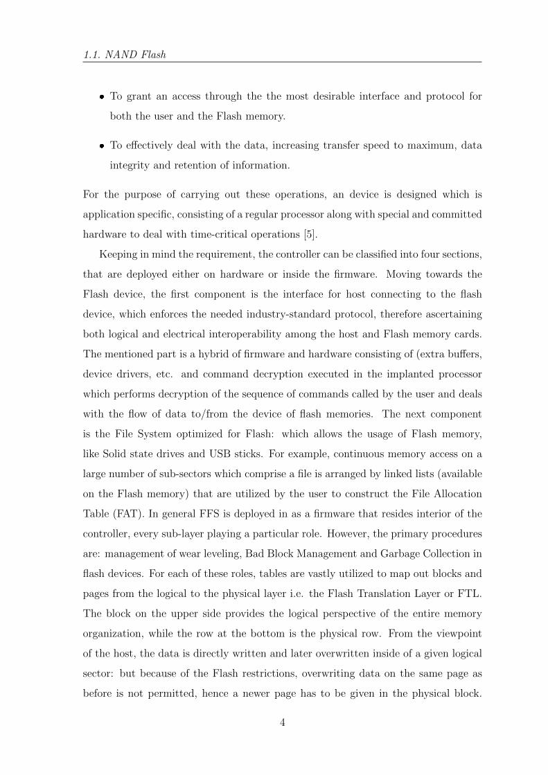
1.1 NAND Flash
In the NAND architecture, the flash cells are arranged in a series in clusters of
32 or 64. NAND flash memory stores information arranged in a particular and very
specific way. Looking at [8], the flash memory memory is classified in structures called
pages and blocks. In flash devices, the smallest erasable unit of memory is a block.
Usually, in any device, the number of blocks is a power of two, for example say 512
blocks, or 4096 blocks. There are multiple pages within each block. Interestingly,
within a block the number of pages that are present is generally a multiple of 16
(e.g. 64, 128). In flash memory, for the purpose of reading and writing, the smallest
addressable unit of memory is a page. Any page comprises two parts, main area and
spare area as shown in fig. 1.1. The size of Main area can be anything from 4 to
8 kB or at times even 16 kB. ECC (Error Correction Codes) utilizes the spare area
in the page and also for system pointers. The size of spare area is in the order of
a hundred bytes every 4 kB of the main area. Each time one attempts to run any
operation on the device, the address where we need to work is to be issued [9]. The
aforementioned is separated into address for rows and columns as depicted in fig.
1.2. The page addressed is identified by row address, while the byte lying within
the interior of the page is addressed by column address. In the case when both row
address as well as column addresses are needed, column address is supplied first, in
order of 8 bits every address cycle. The least significant bits are contained in the first
cycle. The the same address cycle cannot be shared by row and column addresses.
The row address recognizes the page and the block demanded in the operation. The
Page address occupies only the least significant bits.
1.1.1 Memory Controller
The primary task of the flash memory controller provided with NAND Flash is
twofold:
2

INTRODUCTION
Main Area Spare Area
Figure 1.1: NAND page Structure
SYS32 LIB
NAND Flash Device
Hardware Adaptation Layer
LLD BBMECC
FTL Interface
Flash Translation Layer
Wear
Levelling
Garbage
Collection
File System
ECC: Error correction
code
BBM: Bad block
management
LLD: Low Level Driver
Figure 1.2: Application Architecture
3
1.1. NAND Flash
� To grant an access through the the most desirable interface and protocol for
both the user and the Flash memory.
� To effectively deal with the data, increasing transfer speed to maximum, data
integrity and retention of information.
For the purpose of carrying out these operations, an device is designed which is
application specific, consisting of a regular processor along with special and committed
hardware to deal with time-critical operations [5].
Keeping in mind the requirement, the controller can be classified into four sections,
that are deployed either on hardware or inside the firmware. Moving towards the
Flash device, the first component is the interface for host connecting to the flash
device, which enforces the needed industry-standard protocol, therefore ascertaining
both logical and electrical interoperability among the host and Flash memory cards.
The mentioned part is a hybrid of firmware and hardware consisting of (extra buffers,
device drivers, etc. and command decryption executed in the implanted processor
which performs decryption of the sequence of commands called by the user and deals
with the flow of data to/from the device of flash memories. The next component
is the File System optimized for Flash: which allows the usage of Flash memory,
like Solid state drives and USB sticks. For example, continuous memory access on a
large number of sub-sectors which comprise a file is arranged by linked lists (available
on the Flash memory) that are utilized by the user to construct the File Allocation
Table (FAT). In general FFS is deployed in as a firmware that resides interior of the
controller, every sub-layer playing a particular role. However, the primary procedures
are: management of wear leveling, Bad Block Management and Garbage Collection in
flash devices. For each of these roles, tables are vastly utilized to map out blocks and
pages from the logical to the physical layer i.e. the Flash Translation Layer or FTL.
The block on the upper side provides the logical perspective of the entire memory
organization, while the row at the bottom is the physical row. From the viewpoint
of the host, the data is directly written and later overwritten inside of a given logical
sector: but because of the Flash restrictions, overwriting data on the same page as
before is not permitted, hence a newer page has to be given in the physical block.
4

INTRODUCTION
The prior page which is no longer needed is tagged as junk. It is understood that,
at a given point or the other in time, the present physical block is out of space and
hence a second one is attributed to the same logical block. The necessary translation
tables are invariably kept on the flash memory itself, hence cutting down the card
capability.
1.1.2 Wear leveling
In general, different information changes at different frequencies, not all the data
kept inside the same memory alters with the same frequency. In some memory loca-
tions data is very frequently updated while in other memory locations, data remains
static for quite some duration - in worst case, for the entire lifetime of the mem-
ory. It’s obvious that the sectors consisting often-altered data are emphasized with a
huge number of write and erase cycles, however the blocks comprising of data altered
seldom remain under lower pressure.
With the objective of mitigating overwrites, it is necessary to control the usage of
each page/block as less as possible and as uniform as possible. Hence, as a result it is
required to monitor the number of read, write and erase cycles performed on each page
of the memory. Apart from this, the largest number of permitted write/erase cycles
for any block has to be conceived: in case of SLC NAND memories, that number is
in the order of 100k cycles, the same number gets reduced to 10k when MLC NAND
memories are utilized in place of SLC NAND memories.
Wear Leveling schemes mainly depend on the idea of translation from logical to
physical layer: every time the user asks for changes to the same (logical) sector, the
flash controller maps the selected sector onto a dissimilar (usually physical) sector in
a dynamic fashion, and meanwhile maintaining an account of the mapping either in a
particular separate table or with the help of pointers. The obsolete copy of the sector
is marked as invalid and entitled for erasure. In this fashion, most of the physical
sectors are equally used, hence keeping the aging below a acceptable value.
For this function two ways of solving that can be implemented: Dynamic Wear
Leveling is generally utilized to complete a user’s request of updating for a sector;
however, Static Wear Leveling can also be carried out, where each sector, even the
5
1.1. NAND Flash
one which is barely altered, is entitled to be re-mapped as soon as its aging varies
from the mean value.
A significant goal of NAND flash memory design has been to decrease the cost
per bit of flash memory and increase chip capacity so that flash memory can stand
against magnetic storage devices like hard disks. The FTL provided with NAND Flash
lacked certain fundamental functions such as wear leveling. This caused degradation in
performance of Flash devices and reduced it longevity. Soon Flash file systems[10] like
JFFS and JFFS2 took over the conventional file systems and eradicated the need for
FTL chips. JFFS was originally developed by Axix Communications in Sweden[11].
It is a Journalling File System designed for NOR Flash. Redhat improved the existing
version of JFFS and launched JFFS2 with support for NAND Flash memory. JFFS2
is a Log Structured File System[12].
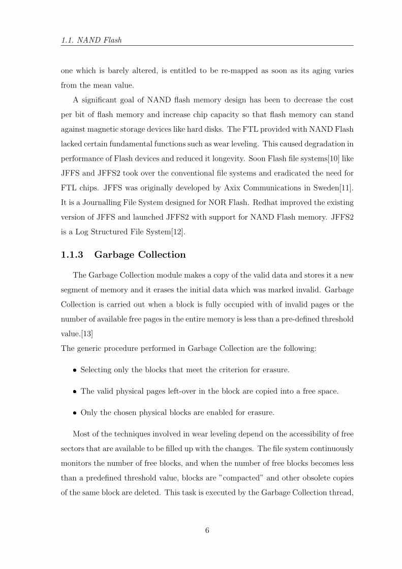
1.1.3 Garbage Collection
The Garbage Collection module makes a copy of the valid data and stores it a new
segment of memory and it erases the initial data which was marked invalid. Garbage
Collection is carried out when a block is fully occupied with of invalid pages or the
number of available free pages in the entire memory is less than a pre-defined threshold
value.[13]
The generic procedure performed in Garbage Collection are the following:
� Selecting only the blocks that meet the criterion for erasure.
� The valid physical pages left-over in the block are copied into a free space.
� Only the chosen physical blocks are enabled for erasure.
Most of the techniques involved in wear leveling depend on the accessibility of free
sectors that are available to be filled up with the changes. The file system continuously
monitors the number of free blocks, and when the number of free blocks becomes less
than a predefined threshold value, blocks are ”compacted” and other obsolete copies
of the same block are deleted. This task is executed by the Garbage Collection thread,
6
INTRODUCTION
it chooses the blocks consisting of invalid blocks, makes a copy of the latest valid block
into free blocks and erases rest of the obsolete blocks.
For the purpose of minimizing the effect on performance, it is also possible to
carry out garbage collection in the background. The balance created by the wear
leveling disseminates the wear out stress over the array of blocks instead of on some
particular hot spots. Hence, the larger the memory density, the lesser the wear out
per cell would be.
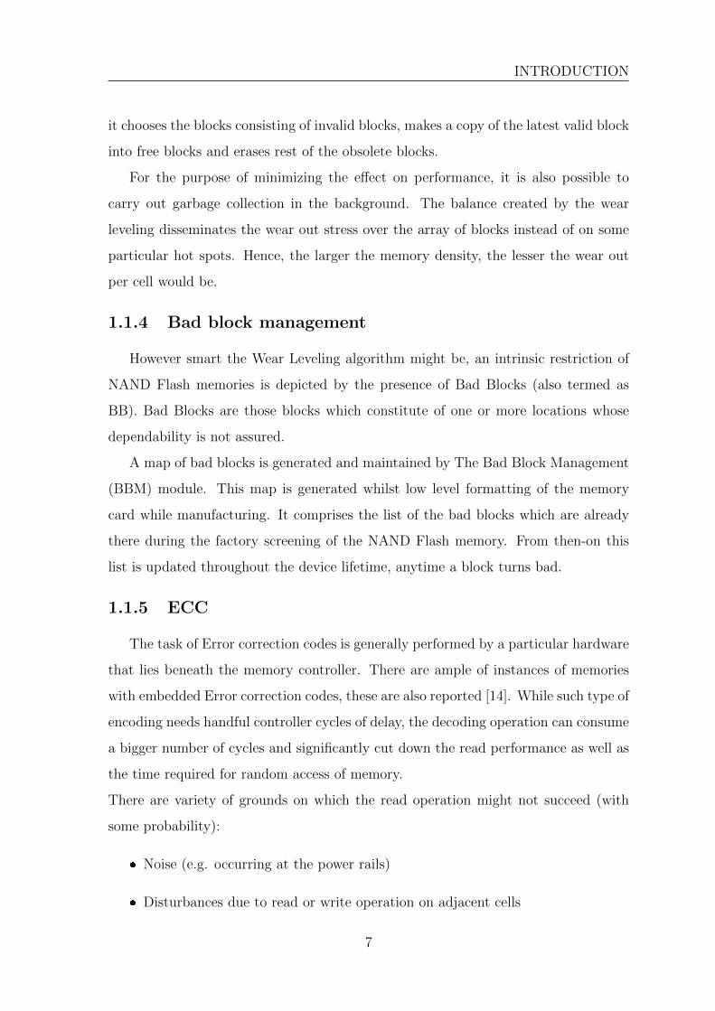
1.1.4 Bad block management
However smart the Wear Leveling algorithm might be, an intrinsic restriction of
NAND Flash memories is depicted by the presence of Bad Blocks (also termed as
BB). Bad Blocks are those blocks which constitute of one or more locations whose
dependability is not assured.
A map of bad blocks is generated and maintained by The Bad Block Management
(BBM) module. This map is generated whilst low level formatting of the memory
card while manufacturing. It comprises the list of the bad blocks which are already
there during the factory screening of the NAND Flash memory. From then-on this
list is updated throughout the device lifetime, anytime a block turns bad.
1.1.5 ECC
The task of Error correction codes is generally performed by a particular hardware
that lies beneath the memory controller. There are ample of instances of memories
with embedded Error correction codes, these are also reported [14]. While such type of
encoding needs handful controller cycles of delay, the decoding operation can consume
a bigger number of cycles and significantly cut down the read performance as well as
the time required for random access of memory.
There are variety of grounds on which the read operation might not succeed (with
some probability):
� Noise (e.g. occurring at the power rails)
� Disturbances due to read or write operation on adjacent cells
7

1.2. YAFFS
� Retention (leakage problems)
The dependability that any memory device can extend is its internal error prob-
ability. This factor of the probability is definitely not that part which the user may
desire. Using ECC it is possible to meet the variance between the desired error prob-
ability and the error probability declared by the device memory.
1.2 YAFFS
YAFFS was the first file system tailor made for NAND Flash memory and is still
better than any file system for native NAND Flash memory. YAFFS was designed and
written by Charles Manning, for the company Aleph One in 2002. The current version
YAFFS2, released in late 2003, has some improvements over the original YAFFS and
introduced forward compatibility to newer chips. YAFFS is a robust log-structured
file system keeps data integrity as a high priority and performance as it’s secondary
priority. The YAFFS codebase is licensed both under the GPL and under per-product
licenses available from Aleph One. YAFFS is a portable file system, i.e. it has been
designed to work on multiple operating systems like linux, WinCE, ThreadX and
many special purpose OSes. It is commonly used in Android Operating System and
also on tonnes of portable media devices using NAND Flash memory. The popularity
and widespread use of YAFFS have led to demand for further optimization, especially
making it a lightweight file system, reducing energy consumption in portable devices.
In this thesis we shall discuss the garbage collection module in YAFFS2, which is one
of the most intensive and frequently used modules[15, 16].
NAND Flash is available at a very competitive price but comes with some limi-
tations in terms of read and write operations. NAND Flash memory felicitates only
sequential reads and writes, unlike NOR Flash memory which supports both sequen-
tial and random reads[17]. For writing on NAND Flash memory, basic unit of data
is a block. A block is made up of one or more chunks, typically 32 to 128 chunks
form a block. The basic unit of erasure is a chunk. Hence this can lead to internal
fragmentation if not checked by the file system. Another limitation in write operation
is that NAND Flash memory does not allow direct overwrite. The file system needs
8

INTRODUCTION
to erase the entire block, only then chunks of that block can be written with data.
The garbage collection module of YAFFS takes care of this by finding dirtiest blocks
and erasing them. In this project we find suitable schemes to decide under what
conditions must YAFFS perform the Garbage Collection[18].
1.3 Terms and Definitions
Garbage Collection heuristics is based on the results of the tests carried on NAND
Flash Memory, here we use a NAND Simulator - nandsim.
� The process of erasing the content of deleted blocks is Garbage Collection.
� Foreground Garbage Collection is the garbage collection performed in the user
thread before a write operation.
� Background Garbage Collection is the garbage collection performed by the back-
ground thread[19].
� Aggressive Garbage Collection is garbage collection in which any dirty block is
picked for erasing.
While in a Passive Garbage Collection only a block which is dirty beyond a
threshold is selected for erasure.
� Erased Blocks are the blocks which are wiped off the existing data post Garbage
Collection or were never written with any data. In YAFFS after a block is
deleted, it undergoes Garbage Collection and then reaches the Erased state.
In simple terms number of erasedblocks determines free space available at the
given instant of time. If deleted blocks are being Garbage Collectioned, number
of erasedblocks will keep increasing.
� Free Chunks are the number of chunks which are either completely empty or in
deleted or erased state. Basically number of freechunks determines total free
space available after Garbage Collection is completed.
9
Chapter 2
Literature Review
While a flash memory device layer can act as a conventional disk drive in order
to use a disk file system on top of the flash device, this is non-optimal on several
grounds:
� Erasing blocks: In Flash memory, there lies a concept of erase-before-write.
Therefore, the blocks need to be erased in an explicit manner, before any data
can be written on to the block. Also, it needs to be considered that the time
needed to clean the blocks can be high, hence it is advised to erase unused blocks
when the device is in idle state.
� Random access: It is also notable that, the disk based file systems have
generally been optimized to ward off disk seeks anytime possible, as the cost of
seeking is considerably high. However, Flash memory devices enforce no delay
in seeks.
� Wear leveling: Most important fact about Flash memory devices is that they
incline to wear out when a particular block is frequently overwritten; therefore
flash file systems are planned keeping in mind to spread out the writes evenly
throughout the disk.
It is observed that all the suitable characteristics for a flash based file system are
present in a Log-structured file systems [20]. A few file system designed to work on
native flash memory without the flash controller, these include the famous JFFS2
and YAFFS[21]. Owing to the peculiar features of flash memory devices, it is advised
10
LITERATURE REVIEW
to be deployed with either a controller that will take care of wear leveling and error
correction or specially designed flash file systems, which spread out write operations
over the memory and handle the large erase times associated with flash devices. The
underlying concept of flash based file systems is: whenever the memory is to be
altered, the file system will create a new copy of the altered data over and place it on
a empty block, it then arranges the file pointers, and finally erases former old block
when it remains idle.
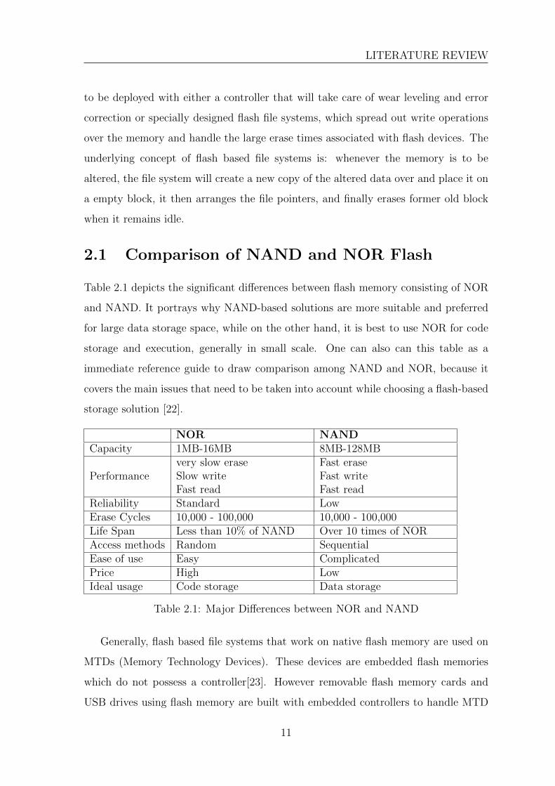
2.1 Comparison of NAND and NOR Flash
Table 2.1 depicts the significant differences between flash memory consisting of NOR
and NAND. It portrays why NAND-based solutions are more suitable and preferred
for large data storage space, while on the other hand, it is best to use NOR for code
storage and execution, generally in small scale. One can also can this table as a
immediate reference guide to draw comparison among NAND and NOR, because it
covers the main issues that need to be taken into account while choosing a flash-based
storage solution [22].
NOR NANDCapacity 1MB-16MB 8MB-128MB
Performancevery slow eraseSlow writeFast read
Fast eraseFast writeFast read
Reliability Standard LowErase Cycles 10,000 - 100,000 10,000 - 100,000Life Span Less than 10% of NAND Over 10 times of NORAccess methods Random SequentialEase of use Easy ComplicatedPrice High LowIdeal usage Code storage Data storage
Table 2.1: Major Differences between NOR and NAND
Generally, flash based file systems that work on native flash memory are used on
MTDs (Memory Technology Devices). These devices are embedded flash memories
which do not possess a controller[23]. However removable flash memory cards and
USB drives using flash memory are built with embedded controllers to handle MTD
11

2.2. Flash memory characteristics
with dedicated algorithms,[24] like wear leveling, recovering from bad block, recovering
from power loss, garbage collection and error correction, therefore using of a flash file
system provides a fixed number of benefits in those fields.
2.1.1 NAND Flash - Performance First
For any Flash device with NAND memory, the erasable unit is a block. It is only
possible to write information to any block if it has free space or if it is erased. There
most of the times it is obvious that an erasure is required to free the block of its
existing dirty data. Given that in a NAND flash memory, it is straightforward to
erase some block, it is vital that all bytes in the block be written to ”zero” before
it can be erased. In general the erase blocks have a size of 64KB to 128KB in NOR
devices (8KB to 32KB in NAND), there this kind of a write/erase operation can take
up to 5 seconds. In gross contrast, the same is performed by NAND in a matter of
mere 4 milliseconds in worst case. The difference in size of the erase block causes
increase in the performance gap of NOR and NAND memory devices, as it has been
observed using statistics that for NOR memory device more erasures must be executed
for any given set of write operations (specially in the case of when altering tiny files).
At a glance comparison of NAND and NOR Flash:
i. NOR can read a bit faster than NAND.
ii. However, write speed of NAND is much faster than NOR.
iii. NAND has a very fast erase operation compared to NOR (4ms vs. 5s).
iv. Erase units are smaller in NAND for fewer erases in less time.
2.2 Flash memory characteristics
As Flash memory became popular, soon file systems for these devices arose and were
put to use the instant they were launched. Some file systems like JFFS (for NOR)
and YAFFS (for NAND) were specially designed considering in mind the constraints
posed by Flash memory. In no time these file systems became a popular choice for
embedded systems which heavily depended on flash memory, it being a modest and
12

LITERATURE REVIEW
affordable solution. In no time problems specific to Flash memory came into picture.
It was noticed that all flash memory devices suffered from damaged blocks after a
while due to wearing of the device after some use. It was noticed that the blocks
written and erased frequently were the ones that easily damaged. Hence wear leveling
techniques were developed in FTL to increase the longevity of Flash drives. In all each
block of a Flash memory, especially NAND has a lifetime of 10,000 to 100,000 uses
only[25]. Now a days FTL has been equipped with better wear leveling techniques,
which perform wear leveling as well as improve the efficiency of the file system in
allocating free blocks when required to write data.
Choosing a flash file system for any purpose depends on many factors that we
shall now discuss below. It is crucial to handle not only the data present in the file
system, but also the Flash itself when using Flash memory for file system storage.
There are many factors that have an impact on the design of the file system [26].
2.2.1 Garbage Collection
A garbage collection procedure is required in flash memory, because it is necessary to
erase the contents of a memory location before any new data can be written onto it.
A Flash memory device is divided into blocks, these blocks are the basic unit of erasure
and hence be erased altogether. The size of these blocks is generally multiple times
of a page, which is the basic write unit of a flash memory device. However, a block
contains both useful and deleted data. The process of reclaiming the dirty pages is as
follows, valid pages containing data is copied to a new memory block which has free
pages and the old block is then completely erased, readying it to be used in future.
However, as the time needed to make a copy of valid pages and erase the entire block
can be high, some file systems have the concept of garbage collection in a background
process performed when the device remains idle.
2.2.2 Wear Leveling
There are only a certain number of write-erase cycles that can be performed on any
Flash memory device, after that the block of memory cannot guarantee the integrity
of the stored data. Therefore the file system maintains a record of number of erase
13
2.2. Flash memory characteristics
cycles performed on every block. Keeping that in account, it determines which block
should be used for the next write task. Also some devices have a restriction on
number of reads permitted between erases, so still data has to be rewritten to ensure
integrity. The goal of maximizing the life span is achieved with the help of wear
leveling techniques. It moves the data among blocks in the file system in such a way
that there is even distribution of number of erases among the blocks of a device.
2.2.3 Sequential Write
Flash memory is designed in a way that there are multiple pages in a block of memory.
But during erasure, the entire block has to be erased, not the single page. Only the
write operation in performed on a page level. Generally these pages are written
sequentially in a block. Also the number of write tasks in a page is limited.
2.2.4 File System Efficiency
File systems enforce a structural organization on the data being written on the flash
memory device. Generally, this is inclusive of the data as well as the metadata that is
to be stored on the file system. Metadata consists of terms like as directories, owner,
creation time. The overhead of writing this data varies based on the design of the
file system. It is to be noted that the overhead varies depending on the goal of the
file system, the ones designed for large multimedia files will have a bigger overhead,
while the ones designed for a smaller data will have smaller overhead. The usage of
memory, requirements of performance, and even the capacity of storage of a disk will
affect the overall file system overhead.
2.2.5 Performance
The throughput associated with read and write operation is limited by the design of
the file system. Apart from throughput, many factors can affect the performance of
a file system. These factors can include values like searching for a file, time required
to delete a file and mount time.
14

LITERATURE REVIEW
2.2.6 ECC
To ensure validity of the data ECC is necessary in NAND Flash memory. Depending
on the type and size of device, the number of bits of needed for ECC to correct
anticipated read errors keeps varying. When ECC uses 1-bit, the software usually
provides the ECC computation without major performance abasement. If in any case
two or more ECC bits are needed, it is desirable to use hardware ECC to keep up the
performance.
2.3 NAND Flash - File Systems
In NAND Flash memory the erase operations are performed at the pace of only one
block at a time, therefore the it requires relatively long erase times. However, with
the advancement of FTL technology, the time required for erasure has significantly
reduces. The FTL does not erase the same block which has to be re-written, rather
it writes the information to another physical page and tags the information stored
in the previous page as invalid. The role of garbage collection module is to empty
this invalid memory space and to allow further operations. Garbage collection is an
important aspect of Flash File Systems, in fact it is one of the fundamental modules
of the file system in handling free space. Garbage collection in NAND flash devices
is performed in two ways, viz. Background Garbage collection and as-needed basis of
Garbage collection. Both these techniques are used in all major Flash File systems and
are indispensable given the flash memory architecture. In some newer File systems
such as F2FS, one more factor such as age of the block segment about to be garbage
collected, is considered in garbage collection, in an attempt to select dirty blocks
more effectively[27]. However, F2FS assumes the existense of FTL and works on the
upper layer of FTL, unlike YAFFS and JFFS and hence it is beyond the scope of this
project.
15

2.3. NAND Flash - File Systems
Here is a summary of major file systems compatible with NAND Flash and their
Garbage collection features, how they evolved over the years.
File System Year Derivative GarbageCollection
Remarks
JFFS 1999 Log-structuredFile Sys-tem (LFS)
Yes, Only onas-needed ba-sis
The garbage collectorcauses a bottleneck inwrite performance
JFFS2 2001 JFFS +LFS
Yes, Bothbackgroundas well asas-neededbasis
The garbage collectorperforms better thanJFFS, but still scopefor improvement in se-lecting bad blocks
YAFFS 2002 JFFS2 +LFS
Yes, Bothbackgroundand fore-ground, writedriven
The garbage collectoruses the same algo-rithm as JFFS2 how-ever, the global badblock classification isnot used, reducing thetime consumed in stateof blocks and findingdirtiest blocks
YAFFS2 2003 YAFFS Yes, Bothbackgroundand fore-ground, writedriven
The garbage collectoris same as YAFFS
Table 2.2: Summary of Flash File Systems
16
LITERATURE REVIEW
2.4 Motivation
Initially NAND Flash memory devices were shipped with an additional Flash
Translation Layer (FTL). The FTL is a software layer that emulates a hard disk with
flash memory in order to provide services to sector I/O requests from a file system
like FAT. A regular file system like ext3, or FAT or NTFS cannot directly utilize a
NAND Flash memory due to it’s fundamentally different architecture. This layered
approach in the file system prevents optimal performance of the storage device. A
native file system like YAFFS eliminates the need for FTL, directly interacting with
the MTD driver (Memory Technology Devices).
In order to defeat the ”erase before write” design constraint [28], the best perfor-
mance is exhibited by sector mapping strategy. In this approach the erase is delayed
to an extent to which there in no free space available and it is utmost important to
free space. Nevertheless, given that the sector mapping strategy needs a significant
amount of mapping data, it is hard to be applied in embedded applications. Thus,
the block mapping along with the hybrid strategy are addressed to solve these prob-
lems. The block mapping strategy needs the least mapping data. But, it is prone to
very poor endurance when the same logical sectors are often altered. In order to get
over the ’updating the same logical sector numbers often’ the hybrid mapping strat-
egy can be used but it requires more mapping information than the block mapping
strategy.[29]
It is important to consider how mapping data will be handled while designing
the FTL. As of now two techniques exist for mapping data, viz. the map block and
the per block technique. A number of special blocks dedicated to storing data with
regard to mapping is required by the map block technique. However, the mapping
information is stored within each block in the per block mapping technique. It is
necessary to consider the RAM usage when implementing the FTL algorithms. In
today’s date, FTL algorithms utilize RAM to the keep data regarding the logical-to-
physical mapping, of free space, and of wear-leveling.
A variety of algorithms for FTL implementation were shown, in this case sector
mapping, FMAX, Log scheme were implemented, and results of the performance were
17
2.5. Problem Statement
presented. The performance of FTL is taken to be clearly bad if only one logical block
happens to be mapped onto one physical block. The FTL performance can be bettered
by utilizing space sectors and replacement blocks (as done in FMAX). The operation
of merging remains as a important factor in the overall performance, if a logical block
is to be mapped to multiple blocks in any of the chosen FTL algorithms. A decent
result is presented by the log scheme with its use of tiny log blocks and multiple data
blocks.
Garbage collection being one of the most intensive modules of any Flash file sys-
tem, it is of paramount importance that it be working efficiently. Hence we focus this
work on Garbage collection schemes and propose and optimized scheme for garbage
collection in YAFFS2 File System. The proposed scheme is tested experimentally and
results were the major driving factor in choosing this scheme over any other.
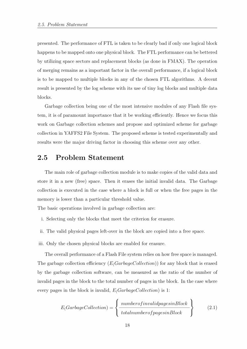
2.5 Problem Statement
The main role of garbage collection module is to make copies of the valid data and
store it in a new (free) space. Then it erases the initial invalid data. The Garbage
collection is executed in the case where a block is full or when the free pages in the
memory is lower than a particular threshold value.
The basic operations involved in garbage collection are:
i. Selecting only the blocks that meet the criterion for erasure.
ii. The valid physical pages left-over in the block are copied into a free space.
iii. Only the chosen physical blocks are enabled for erasure.
The overall performance of a Flash File system relies on how free space is managed.
The garbage collection efficiency (E(GarbageCollection)) for any block that is erased
by the garbage collection software, can be measured as the ratio of the number of
invalid pages in the block to the total number of pages in the block. In the case where
every pages in the block is invalid, E(GarbageCollection) is 1:
E(GarbageCollection) =
numberofinvalidpagesinBlock
totalnumberofpagesinBlock
(2.1)
18

LITERATURE REVIEW
A huge number of pages have be copied into fresh blocks before erasing the selected
block when the efficiency of garbage collection for the chosen block is low. As the
number of pages to be copied increased, the number of write operations also rises,
this in turn reduces the life span of NAND Flash devices.
One more important factor to be considered in case of garbage collection is the
volume of free space in the flash memory. Emptying sufficient space in memory to fit
data instantly when the user requests, can better the the File systems throughput.
Throughput is measured using the READ/WRITE throughput, keeping in mind the
overhead of the file system.
Invariably, the user has to wait for the system to perform garbage collection and
free up some space by erasing invalid block when the total number of pages to be
entered surpasses the number of available free pages. However, this situation can
only be warded off by implementing garbage collection on a regular basis Before we
delve upon defining the problem, let us review the characteristics of YAFFS2 File
system, which we can utilize to optimize Garbage collection.
Problem characteristics:
i. Most of the time the File System remains idle, there are a few write bursts
occasionally.
ii. Unless the File System is running out of free chunks, Garbage Collection can and
should be avoided.
iii. Aggressive Garbage collection is performed only when free chunks are very low,
and deleted blocks are above a threshold value.
(Note: Aggressive Garbage Collection requires most computing and read write
operations, hence its best avoided)
Taking into consideration these points, we can describe the problem statement pre-
cisely. The aim of this project is to minimize the number of Aggressive Garbage
Collections performed by the File System. Ideally the number can be brought down
to zero if there is always sufficient free space in the file system. But in practical
applications, many time the flash memory is used rigorously, and in cases when the
19

2.5. Problem Statement
free space in the memory is depleting, and the number of deleted blocks are rising,
Aggressive Garbage Collection has to be performed to free space for the write thread
which requires empty blocks to write data. To define the problem formally, we can
state it as follows:
i. Minimize the number of Aggressive Garbage Collections and in turn allow more
background Garbage Collections.
ii. Find a threshold value β, below which background Garbage Collections must be
performed, where
β =
nErasedChunks
nFreeChunks
(2.2)
As reported in the literature, the default value of β used by YAFFS2 is known to
be 1/4.
20

Chapter 3
Proposed Algorithm
3.1 Blocks and Page structure in YAFFS
Prior to explaining the approach to the problem, let us recollect the significance
of garbage collection module in performance of any flash based file system. In NAND
flash devices, the architecture demands only one page to be read or written at anytime
and one entire block to be erased at a single instance as shown in fig 3.1. During the
erase operation all the bits in the block are manually set to ”1”. After that starting
with any freshly erased block, it is possible to write data to any page inside the block.
Once data is written, some bits wil be set to ”0” and some to ”1”. After this the
only technique to reset a bit to ”1” is the erase the complete block all over again.
Sophisticated management techniques for the blocks are deployed to minimize the
number of erase operations and to enhance the life span of flash memory device.
Block (256 KB)
} Minimal
write sizeMinimal
erase size{Figure 3.1: Page write vs. erase block
21

3.1. Blocks and Page structure in YAFFS
many times bits in NAND flash get flipped due to variety of reasons; bits that
are not being read or written also happen to be altered sometimes because of read or
write task carried out in adjacent cells. Note that MLC NAND is more prone to such
bit flips than SLC NAND.
Read Disturb
When a flash cell which is not being read receives spiked voltage stress a read
disturb occurs. Note that cells that are stressed always lie in the block in which
a page is being read and are always on a page which isn’t currently being read.
The probability that a read disturb will occur is quite smaller than that of a
write disturb.
Write Disturb
When any flash cell which isn’t being written receives spiked voltage stress, a
write disturb takes place. It is to be noted that cells that are stressed will always
lie in the block in which some cell is being written, this can be either on the
page that is written (but the cell wasn’t chosen), or on any random page lying
inside the block.
Erasing a cell will reset it to it’s initial state, removing the data and, simultane-
ously the errors in data which arose from the read or write disturbs. An ECC control
strategy in the path of data flow detects if there have been any bit flips and rectifies
them before sending the data to the user. As the density of flash cells increase and
greater number of cells are embedded onto the chips, the probability of errors and bit
flips rises and controllers for NAND flash need more reliable error correction schemes.
Clearly NAND Flash has many hardware limitations which need to be overcome by
the help of the file system managing the NAND device directly. As we have discovered
that entire performance of entire file system is driven by garbage collection module,
we have focused the work on optimizing the garbage collection scheme to improve
the over all performance of this file system. On unearthing the garbage collection
scheme we find that Aggressive Garbage collection module is lot more intensive than
the passive garbage collection module, and it impacts the performance of the file
22
PROPOSED ALGORITHM
system in a negative manner. Aggressive Garbage collection uses lot more CPU
cycles than any other module, hence delaying any important write operation. In
mission critical systems, this small overhead can also cause mission failure in critical
systems. Therefore any reduction in number of Aggressive Garbage collections will
impact the performance of the file system, increasing its reliability, responsiveness
and availability to the other important processes.
In this chapter we discuss the proposed changes to YAFFS garbage collection
module that will optimize the number of times it is run in different scenarios. In the
algorithm discussed below, we find the value of β which gives us the most optimal
result. The default value of β is 1/4 in YAFFS2.
3.2 Role of β in Proposed Algorithm
The proposed algorithm makes use of the following variables, let us see that these
variables are and what is the significance and function of each of these variables:
background
A Boolean variable denoting the type of Garbage Collection, i.e. background
or foreground. By convention, if background = true, it implies the Garbage
collection thread is running in background mode. In case when background
= false, we know that the Garbage Collection thread is running in foreground
mode.
aggressive
An Integer variable denoting the nature of Garbage Collection module, i.e. ag-
gressive or passive. By convention, if aggressive = 1, it implies that the garbage
collection thread is running in aggressive mode which is more expensive than
passive mode. When aggressive = 0, it is taken that the garbage collection
thread is running in passive mode. If the garbage collection is aggressive the
whole block is collected in a single garbage collection cycle. If the garbage col-
lection is passive then the number of copies is reduced, thus spreading effort
over many garbage collection cycles. This is done to reduce garbage collection
load and improve responsiveness.
23

3.2. Role of β in Proposed Algorithm
nErasedBlocks
An Integer variable that keeps track of the number of erased blocks available for
write operation after Garbage Collector or a free block available for write oper-
ation. As soon as any block is deleted, the number of nErasedBlocks increases
reflecting the changes caused by deletion.
reservedBlocks
An Integer variable to determine number of reserved blocks. For the purpose
of garbage collection, the heuristics try to delay garbage collection as long as
possible and prioritize other tasks. But a threshold value needs to be set, below
which it becomes utmost essential to perform garbage collection. This threshold
value is the number of reserved blocks, i.e. reservedBlocks. If the number of
free blocks falls below this value, aggressive garbage collection is performed to
free blocks before any further writes.
nErasedChunks
An Integer variable that keeps track of the number of erased chunks. Its value
is calculated from nErasedBlocks, by multiplying with a constant value (32 or
64, depending on number of chunks in a block).
nFreeChunks
An Integer variable that keeps track of the number of free chunks at any given
time. There is a difference in free chunks and erased chunks, once deleted
the number of free chunks rises instantly depicting the free space, but number
of erased chunks actually denote the free space, it does not include the space
occupied by deleted data which is yet to be garbage collected.
beta(β)
A fraction determining the threshold whether to perform Garbage Collection or
not. As defined earlier β is equal to number of erased chunks divided by the
number of free chunks in the device at any given time.
24

PROPOSED ALGORITHM
Algorithm 3.1: Garbage Collection
if (nErasedBlocks < reservedBlocks) then1
aggressive=1;2
else3
if (!background && nErasedChunks > (β ∗ nFreeChunks)) then4
exit;5
end6
if (background || nErasedChunks < nFreeChunks/2) then7
aggressive=0;8
else9
exit;10
end11
end12
In the above mentioned algorithm, we observe that value of β plays a key role
in determining the number of Aggressive Garbage Collections. If number of reserved
blocks is less than the number of erased blocks (erased after Garbage Collection
and initially free) then Aggressive Garbage Collection is inevitable. Otherwise, if
the Garbage Collection is in foreground mode and number of erased chunks (erased
after Garbage Collection and initially free) is greater than β times number of free
chunks (deleted and initially free) then Aggressive Garbage Collection is performed.
If Garbage Collection is in background mode or number of erased chunks (erased
after Garbage Collection and initially free) is less than half the number of free chunks
(deleted and initially free) then Passive Garbage Collection is performed. In any other
case Garbage Collection is not performed.
25

Chapter 4
Analytical Study
Before rushing off to simulations and testing the result of proposed algorithm, it
is necessary to know that the approach adopted in the mentioned algorithm is correct
and shall give results consistent with the approach. For the same purpose we examine
the proposed algorithm analytically in this chapter. For the purpose of testing the
proposed algorithm on paper, let us consider 3 scenarios and see how the algorithm
handles each of of them differently. Let us assume the value of β to be 1/4 which is
the default value for YAFFS2.
4.1 Scenario 1
Consider a case where the disk is partially filled with data. The number of erased
chunks is greater than the threshold value, i.e. the number of reserved blocks. Also
assume that the garbage collection thread is initiated by the write module and that
no data has been erased this far.
On browsing through Algorithm 3.1, on Line 1 the condition is not satisfied, as
it is given that in this case, the number erased blocks are greater than number of
reserved blocks. Next on Line 4, we know that value of background = false, the
garbage collection initiated by the write module, it is a foreground mode of garbage
collection. Also the number of erased chunks is exactly equal to the number of free
chunks, hence the condition of Line 4 and Line 7 is not satisfied and the garbage
collection module exits as there is no need for Garbage collection.
Result: Garbage Collection is not performed in case of no erasures.
26
ANALYTICAL STUDY
4.2 Scenario 2
Consider a case where the disk is partially filled with data. The number of erased
chunks is greater than the threshold value, i.e. the number of reserved blocks. Also
assume that the garbage collection thread is initiated by the write module and that
some data has been erased this far.
On browsing through Algorithm 3.1, on Line 1 the condition is not satisfied, as
it is given that in this case, the number erased blocks are greater than number of
reserved blocks. Next on Line 4, we know that value of background = false, the
garbage collection initiated by the write module, it is a foreground mode of garbage
collection. Also the number of erased chunks is less than half the number of free
chunks, hence the condition of Line 7 is satisfied and the garbage collection module
performs its next cycle in passive mode as the variable aggressive is set to 0. In the
coming cycles when the condition on Line 4 is satisfied, i.e. after recovering some
chunks, garbage collection no longer need to be performed.
Result: Only Passive Garbage Collection is performed in this case.
4.3 Scenario 3
Consider a case where the disk is nearly filled with data. The number of erased
chunks is less than the threshold value, i.e. the number of reserved blocks. Also
assume that the garbage collection thread is initiated by the write module and that
some data has been erased this far.
On browsing through Algorithm 3.1, on Line 1 the condition is satisfied, as it is
given that in this case, the number erased blocks are less than number of reserved
blocks. In this cycle of garbage collection, aggressive flag is set and the first dirty
block is freed until the garbage collection continues in aggressive mode. Once the
number of erased blocks exceeds the threshold value, we observe next on Line 4, we
know that value of background = false, the garbage collection initiated by the write
module, it is a foreground mode of garbage collection. Also the number of erased
chunks is less than half the number of free chunks, hence the condition of Line 7 is
satisfied and the garbage collection module performs its next cycle in passive mode as
27

4.3. Scenario 3
the variable aggressive is set to 0. In the coming cycles when the condition on Line 4
is satisfied, i.e. after recovering some chunks, garbage collection no longer need to be
performed.
Result: Initially aggressive garbage collection is performed, once number of erased
blocks exceed threshold, then only Passive Garbage Collection is performed.
28

Chapter 5
Simulation and Results
In this chapter we evaluate the performance of YAFFS2 file system on NAND
Flash memory with different values of β in the garbage collection module. In order
to study the behavior of garbage collection module, we conduct extensive tests using
NANDSIM, to simulate a NAND Flash memory loaded with YAFFS2. The results
obtained are compared with results from same test performed on default YAFFS2
configuration.
5.1 Simulation
We use a 64MB virtual device, with 32 chunks per block and 512B per chunk. We
perform the write test on this device.
i. Write 60 x 1MB data on the device
ii. Repeat the following 16 times
a. Write 4MB data
b. Delete 4MB data
After each write and delete operation, status of yaffs device is recorded. From this
we extract relevant information like total number of Garbage Collections, number of
background and foreground Garbage Collection, number of Aggressive and Passive
Garbage Collections.
29

5.2. Discussion
For each value of β the write test is repeated six times and average of all six tests
is used for comparison. The same test is performed for JFFS2 garbage collection
scheme and the results are available in the same graphs.
5.2 Discussion
On analyzing of Algorithm 3.1 we see that, the number of Aggressive Garbage
Collections and the number of total Garbage Collections are inversely proportional.
Therefore, by reducing the number of Aggressive Garbage Collections, the number of
total Garbage Collections increase. In order to find the optimal value of β we plot
the change in number of Aggressive Garbage Collections Vs. the change in number
of total Garbage Collections in Figure 5.1. Both values are measured in percentage
taken in comparison with default value of β (1/4).
In fig 5.2 we see the comparison of number of Aggressive Garbage Collections
during the over-write test for various values of β ranging from 1/6 to 99/100. Among
the various values plotted in the curve, we find the maxima of the curve to be at value
of β = 4/5, where the reduction in aggressive garbage collections is 22 % and rise in
all garbage collections is 5 $. It is clear that for β = 4/5, the number of Aggressive
Garbage Collections is the least. This supports the finding of fig 5.1.
To determine the performance of this improved scheme in YAFFS2 in comparison
to other Flash File System, we perform the same test on JFFS2 garbage collector, and
plot its results in the same graph. It is observed that number of Aggressive Garbage
Collections performed by JFFS2 is nearly same as those performed by default value
of β = 4/5 in YAFFS.
5.3 Results
As discussed earlier, we observe from Figure 5.1, that the curve of change in Aggressive
Garbage Collections Vs. change in total Garbage Collections attains maxima at 22.8%
fall in number of Aggressive Garbage Collections, and 4.9% increase in number of total
Garbage Collections, for value of β = 4/5. This implies that the optimum number
of Aggressive Garbage Collections and total Garbage Collections take place when
30

SIMULATION AND RESULTS
99/100 9/10 4/5 7/10 2/3 1/2 1/3 1/4 jffs 1/5 1/6−20
−15
−10
−5
0
5
10
15
20
25
30Aggressive GCs Vs. All GCs
chan
ge in
GC
s(%
)
Value of β
Change in All GCsChange in Aggressive GCs
Figure 5.1: Aggressive Garbage Collections Vs. All Garbage Collections in over-writeTest
in algorithm 3.1 the value of β is substituted with 4/5. So the deciding condition
formulates as nErasedChunks > 4/5 * nFreeChunks for optimal number of Aggressive
Garbage Collections and total Garbage Collections to take place. Also the number
of Aggressive Garbage Collections performed by JFFS2 is slightly larger than default
configuration of YAFFS, and hence the new optimized scheme performs better than
both existing JFFS2 and YAFFS2 garbage collector schemes.
In fig. 5.2, we plot the number of Aggresive Garbage Collections performed for a
certain chosen values of β. Each line in the graph represents, number of Aggressive
Garbage Collections that occur after n(th) over-write. In the devised test plan we
perform 16 over-writes of 1 MB each, and hence the number of Garbage Collections
increases linearly for each over-write. In this graph we observe that for a value of β
= 1/6, maximum number of Aggressive Garbage Collections occur, hence giving the
31

5.3. Results
Value of β Change in AllGarbage Collec-tions (%)
Change in Aggres-sive Garbage Col-lections(%)
β = 99/100 -5.02 19.32
β = 9/10 -4.95 22.19
β = 4/5 -4.92 22.8
β = 7/10 -4.9 19.18
β = 2/3 -4.78 20.28
β = 1/2 -4.01 18.8
β = 1/3 -2.15 7.92
β = 1/4 0 0
JFFS2 0.74 -1.83
β = 1/5 2.22 -5.57
β = 1/6 4.4 -12.45
Table 5.1: Tabular comparison of Aggressive Garbage Collections Vs. All GarbageCollections in over-write Test
worst performance among the selected values of β. We also observe that for a value
of β = 4/5, the number of Aggressive Garbage Collections is the least and hence we
can conclude that optimal performance for number of Aggressive Garbage Collections
is achieved with the value of β being 4/5. Another interesting fact that we observe
in this figure is that, the number of Aggressive Garbage Collections in JFFS2 and
YAFFS default configuration, where β = 4/5 is very close, JFFS2 only exceeding by
marginal values.
32

SIMULATION AND RESULTS
0 2 4 6 8 10 12 14 160
200
400
600
800
1000
1200
1400Aggressive GCs comparison
Num
ber
of A
ggre
ssiv
e G
Cs
Number of over−writes
β = 1/6β = 1/4jffsβ = 1/3β = 99/100β = 4/5
Figure 5.2: Aggressive Garbage Collections comparison in over-write Test
33

Chapter 6
Conclusions and Future Work
6.1 Conclusion
In this project the garbage collection module of YAFFS2 has been discussed.
The proposed changes in the garbage collection algorithm to reduce the number of
Aggressive Garbage Collections. It is observed that for the value of β = 4/5, we get
an optimal value for the number of Aggressive Garbage Collections with a relatively
smaller increase in number of total Garbage Collections.
Every flash based file system requires some or the other technique to replicate
the garbage collector. The performance of garbage collection module can frequently
be considered as a determining component in overall performance of the file system.
YAFFS takes an approach of handling only one block at a given instance which
restricts the volume of effort required in a garbage collection cycle, thus decreasing
the ”stall time”.
Till now we have seen that, a block can be easily erased and recycled when it
is consisting only of deleted pages. But imagine the scenario when when multiple
blocks will have only a few invalid pages and the number of these blocks will be large.
Certainly, the data of these blocks cannot be erased directly, else there would be data
loss and the file system would no longer remain reliable. What can be done is that
make a copy of clean and useful data from the block that needs to be erased and
store that copy on a fresh block that will be available. This underlying process is
the garbage collection in a nutshell. A block is ready to be erased when all the clean
and valid chunks are copied to a new location. After erasing the block it becomes
34

CONCLUSIONS AND FUTURE WORK
available for reuse. In a situation when power is disrupted just after making a copy of
the data, we can distinguish between the original and its copy by checking the serial
number of each block.
The main intention of the above strategy is to delay the process of garbage collec-
tion whenever permitted, to decrease the amount of collection that is required to be
performed, hence the average performance of the system is increased. However there
is a clash of interests, as garbage collection is also preferably performed in a spread
out manner and not all at once. Performing rigorous garbage collection altogether
causes serious impact on the file system throughput. This conflict in end goal makes
tuning of garbage collection a real challenge.
To conclude we can safely state that reducing the number of Aggressive Garbage
Collections is a significant optimization in terms of performance. In a write operation,
a considerable amount of time is spent of finding free chunks to write data, and
Garbage Collections are performed whenever there is scarcity of free blocks to convert
deleted blocks into erased blocks. Therefore by reducing the number of Aggressive
Garbage Collections in write operation, the performance of disk write is also improved.
Reducing the number of Aggressive Garbage Collections frees up processor, making
it available for more computation or speeding up existing processes. It also reduces
the number of erase-writes cycles on the disk, there by increasing it’s longevity. As
Aggressive Garbage Collections are quite heavy on the processor, they consume more
power. Hence by reducing the number of Aggressive Garbage Collections, the energy
consumption of the device is reduced. This is of great significance in battery powered
devices.
6.2 Future Work
This work mainly focuses on fixed disk size of 64MB, however an endeavor will be
made in future to explore possibilities of heuristics based on disk capacity, chunk size
and any other factors found influencing the number of Aggressive and total Garbage
Collections.
In future we intend to compare Garbage Collection algorithm in F2FS (Flash
35
6.2. Future Work
Friendly File System), which also supports NAND Flash. YAFFS2 currently supports
maximum file size of 2GB only, this can be modified and support for larger files can
be implemented. Wear leveling in YAFFS2 is only an effect of the File System being
a Log-structured File System, a better wear leveling technique can be implemented to
extend the life of NAND flash devices. YAFFS2 has a naive cache system especially for
some applications which require and write very few number of chunks very frequently.
36

Bibliography
[1] Roberto Bez, Emilio Camerlenghi, Alberto Modelli, and Angelo Visconti. Introduction
to flash memory. In Proceedings of the IEEE, pages 489–502, 2003.
[2] C Golla and S Ghezzi. Flash memory architecture. Microelectronics Reliability,
38(2):179 – 184, 1998.
[3] Microsoft Corporation. FAT: General Overview of On-Disk Format, 2000.
[4] Intel Corporation. Understanding the Flash Translation Layer (FTL) specification.
Intel Corporation, Dec 1998. Application Note AP-684.
[5] Jesung Kim, Jong Min Kim, S.H. Noh, Sang-Lyul Min, and Yookun Cho. A space-
efficient flash translation layer for compactflash systems. Consumer Electronics, IEEE
Transactions on, 48(2):366–375, May 2002.
[6] T. Shinohara. Flash memory card with block memory address arrangement, May 18
1999. US Patent 5,905,993.
[7] Esther Spanjer. WP001 - Flash Management, 2012.
[8] MICRON. TN-29-19. NAND Flash 101: An Introduction to NAND Flash and How to
Design It In to Your Next Product. http://download.micron.com/pdf/technotes/
nand/tn2919.pdf, 2006.
[9] Po-Chun Huang, Yuan-Hao Chang, Tei-Wei Kuo, Jen-Wei Hsieh, and Miller Lin. The
behavior analysis of flash-memory storage systems. In Object Oriented Real-Time Dis-
tributed Computing (ISORC), 2008 11th IEEE International Symposium on, pages
529–534, May 2008.
37

Bibliography
[10] Cliff Brake. Flash file system for embedded linux systems. Linux Journal, Jul 2001.
[11] David Woodhouse. The Journalling Flash File System (JFFS). Technical Report
RedHat inc., 2001.
[12] Luca Boschetti. Software Profile: Journaling Flash File System, Version 2 (JFFS2),
2011.
[13] MICRON. Garbage Collection in Single-Level Cell NAND Flash Memory, 2004.
[14] T. Tanzawa, T. Tanaka, K. Takeuchi, R. Shirota, S. Aritome, H. Watanabe, G. Hemink,
K. Shimizu, S. Sato, Y. Takeuchi, and K. Ohuchi. A compact on-chip ecc for low cost
flash memories. Solid-State Circuits, IEEE Journal of, 32(5):662–669, May 1997.
[15] Charles Manning. YAFFS: the NAND-specific flash file system - Introductory Article.
published at Linuxdevices.org, Sept 2002.
[16] Charles Manning. How yaffs works. http://yaffs.net/documents/
how-yaffs-works.
[17] Eran Gal and Sivan Toledo. Algorithms and data structures for flash memories. ACM
Computing Surveys, 37:2005, 2005.
[18] Michael Spreitzenbarth, Sven Schmitt, and Christian Zimmermann. Reverse engi-
neering of the android file system (yaffs2). Technical Report CS-2011-06, Technische
Fakultat -ohne weitere Spezifikation-, 2011.
[19] Charles Manning and Wookey. YAFFS Update, 2010.
[20] Arnd Bergmann. Optimizing linux with cheap flash drives. LWN.net, Feb 2011.
[21] Charles Manning. Comparision between yaffs2 and jffs2, 19992007.
[22] Arie Tal. Two flash technologies compared: Nor vs nand. White Paper of M-Systems,
Oct 2002.
[23] A. Ban. Flash file system, April 4 1995. US Patent 5,404,485.
38

Bibliography
[24] R. Micheloni, A. Marelli, and S. Commodaro. Nand overview: from memory to systems.
In Inside NAND Flash Memories, pages 19–53. Springer Netherlands, 2010.
[25] Dawoon Jung, Yoon-Hee Chae, Heeseung Jo, Jin-Soo Kim, and Joonwon Lee. A group-
based wear-leveling algorithm for large-capacity flash memory storage systems. In Pro-
ceedings of the 2007 International Conference on Compilers, Architecture, and Syn-
thesis for Embedded Systems, CASES ’07, pages 160–164, New York, NY, USA, 2007.
ACM.
[26] Kurt Sowa. Choosing a Linux File System for Flash Memory Devices.
http://www.micron.com/~/media/Documents/Products/Software%20Article/
SWNL_choosing_linux_fs_for_flash.pdf, 2011.
[27] Jaegeuk Kim. Flash-Friendly File System (F2FS) Documentation. https://www.
kernel.org/doc/Documentation/filesystems/f2fs.txt, 2013.
[28] R.E. Fackenthal. Multiple non-contiguous block erase in flash memory, June 8 2004.
US Patent 6,748,482.
[29] Tae-Sun Chung, Dong-Joo Park, Sangwon Park, Dong-Ho Lee, Sang-Won Lee, and
Ha-Joo Song. A survey of flash translation layer. Journal of Systems Architecture,
55(5-6):332 – 343, 2009.
39