GainMaker Amplifier AGC Module Replacement Installation ... · GainMaker Amplifier AGC Module...
28
GainMaker Amplifier AGC Module Replacement Installation Instructions Overview Introduction This document explains how to replace an automatic gain control (AGC) module in a GainMaker ® System Amplifier and GainMaker Line Extender amplifier. This replacement procedure should be performed on amplifiers that require an AGC module other than the one that was factory-installed. Audience These instructions are intended for service personnel who are responsible for installing and maintaining GainMaker products. The personnel should have experience with hardware component installation. Document Version This is the third release of this document. Related Publications Refer to the following publications for more information about GainMaker amplifiers. GainMaker Broadband Amplifier Platform System Amplifier Modules and Housings Installation and Operation Guide, part number 593161 GainMaker Broadband Amplifier Platform Line Extender Modules and Housings Installation and Operation Guide, part number 593057 Continued on next page
Transcript of GainMaker Amplifier AGC Module Replacement Installation ... · GainMaker Amplifier AGC Module...
GainMaker Amplifier AGC Module Replacement Installation Instructions
Overview
Introduction
This document explains how to replace an automatic gain control (AGC) module in a GainMaker® System Amplifier and GainMaker Line Extender amplifier. This replacement procedure should be performed on amplifiers that require an AGC module other than the one that was factory-installed.
Audience
These instructions are intended for service personnel who are responsible for installing and maintaining GainMaker products. The personnel should have experience with hardware component installation.
Document Version
This is the third release of this document.
Related Publications
Refer to the following publications for more information about GainMaker amplifiers.
GainMaker Broadband Amplifier Platform System Amplifier Modules and Housings Installation and Operation Guide, part number 593161
GainMaker Broadband Amplifier Platform Line Extender Modules and Housings Installation and Operation Guide, part number 593057
Continued on next page
2 GainMaker Amplifier AGC Module Replacement Installation Instructions 748051 Rev C
Overview, Continued
In These Installation Instructions
These installation instructions contain the following topics.
Topic See Page
System Amplifier AGC Module Replacement 3
Line Extender AGC Module Replacement 13
For Information 26
748051 Rev C GainMaker Amplifier AGC Module Replacement Installation Instructions 3
System Amplifier AGC Module Replacement
Introduction
The steps required to replace an AGC module in a system amplifier vary, depending on whether or not the system amplifier is located in the field.
The following is a list of all possible steps:
Disconnecting power from the system amplifier
Removing the amplifier module from the housing
Replacing the AGC module
Repositioning the amplifier module in the housing
Reconnecting power to the system amplifier
Closing the system amplifier housing
Re-boxing the system amplifier
Required Tools and Equipment
Before you start, make sure you have the following tools and equipment:
Replacement AGC module (provided with these instructions)
Torque wrench with a 1/2-in. socket
Flat-head screwdriver
Screwdriver appropriate for the type of screws on the amplifier module cover
Phillips-head screwdriver
T-15 Torx bit screwdriver
Two product labels (provided with these instructions)
3”x 1” amplifier chassis label
3”x 2” box label (for amplifiers not located in the field)
Continued on next page
4 GainMaker Amplifier AGC Module Replacement Installation Instructions 748051 Rev C
System Amplifier AGC Module Replacement, Continued
Disconnecting Power From the System Amplifier
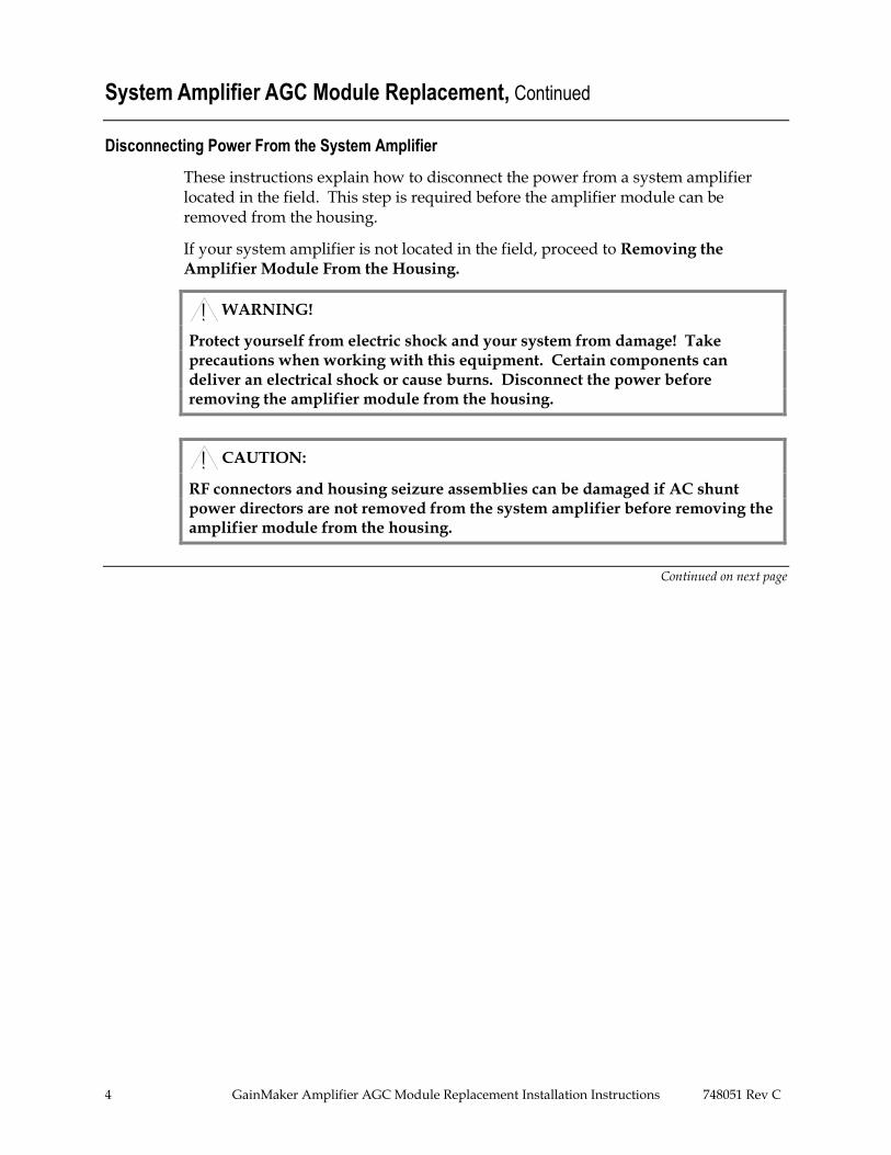
These instructions explain how to disconnect the power from a system amplifier located in the field. This step is required before the amplifier module can be removed from the housing.
If your system amplifier is not located in the field, proceed to Removing the Amplifier Module From the Housing.
WARNING!
Protect yourself from electric shock and your system from damage! Take precautions when working with this equipment. Certain components can deliver an electrical shock or cause burns. Disconnect the power before removing the amplifier module from the housing.
CAUTION:
RF connectors and housing seizure assemblies can be damaged if AC shunt power directors are not removed from the system amplifier before removing the amplifier module from the housing.
Continued on next page
748051 Rev C GainMaker Amplifier AGC Module Replacement Installation Instructions 5
System Amplifier AGC Module Replacement, Continued
Follow these steps to disconnect the power from a system amplifier located in the field.
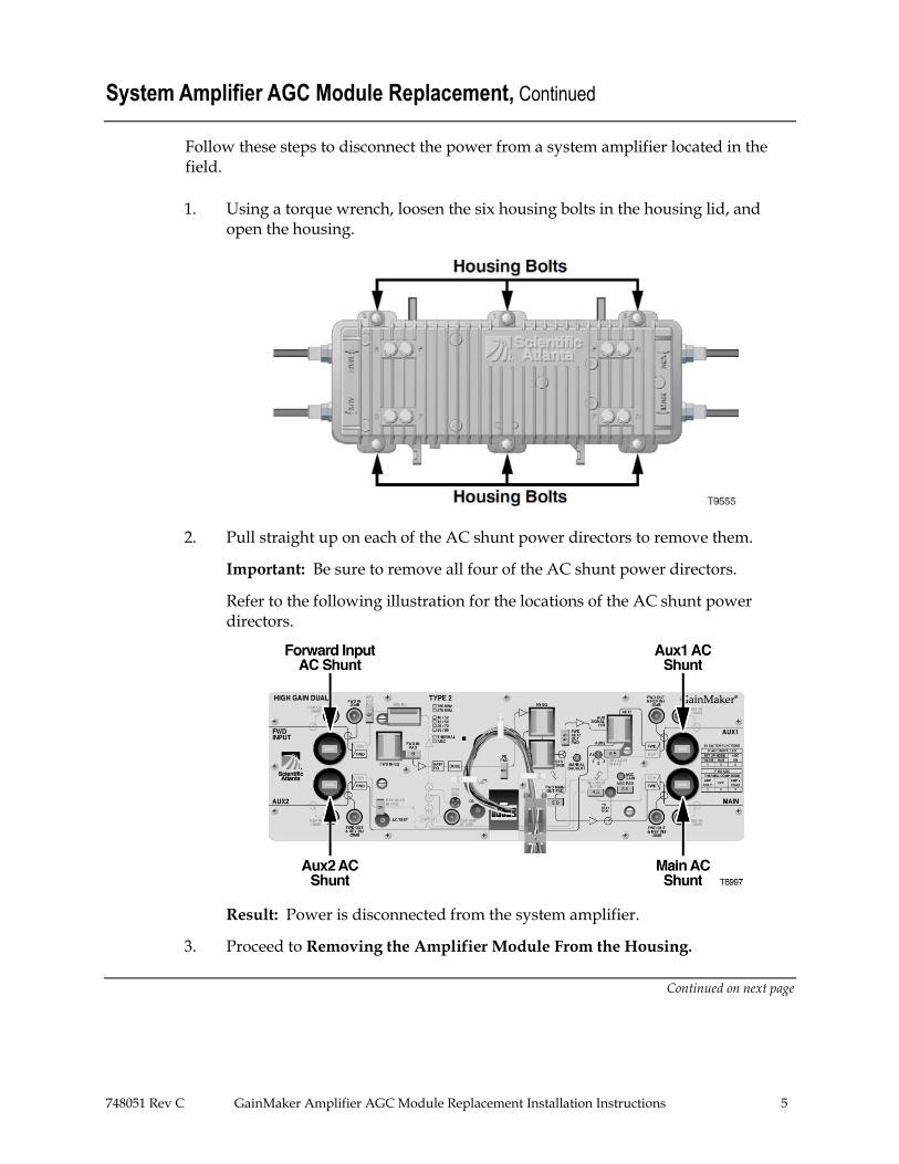
1. Using a torque wrench, loosen the six housing bolts in the housing lid, and open the housing.
2. Pull straight up on each of the AC shunt power directors to remove them.
Important: Be sure to remove all four of the AC shunt power directors.
Refer to the following illustration for the locations of the AC shunt power directors.
Result: Power is disconnected from the system amplifier.
3. Proceed to Removing the Amplifier Module From the Housing.
Continued on next page
6 GainMaker Amplifier AGC Module Replacement Installation Instructions 748051 Rev C
System Amplifier AGC Module Replacement, Continued
Removing the Amplifier Module From the Housing
Important: If the system amplifier is located in the field, refer to Disconnecting
Power From the System Amplifier earlier in this section before removing the amplifier module from the housing.
Follow these steps to remove the amplifier module from the housing.
1. Is the system amplifier housing open?
If Yes, proceed to step 2.
If No:
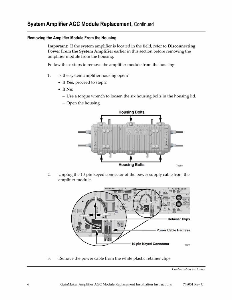
Use a torque wrench to loosen the six housing bolts in the housing lid.
Open the housing.
2. Unplug the 10-pin keyed connector of the power supply cable from the amplifier module.
3. Remove the power cable from the white plastic retainer clips.
Continued on next page
748051 Rev C GainMaker Amplifier AGC Module Replacement Installation Instructions 7
System Amplifier AGC Module Replacement, Continued
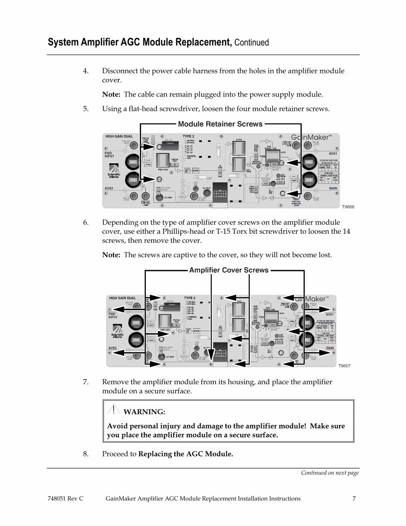
4. Disconnect the power cable harness from the holes in the amplifier module cover.
Note: The cable can remain plugged into the power supply module.
5. Using a flat-head screwdriver, loosen the four module retainer screws.
6. Depending on the type of amplifier cover screws on the amplifier module cover, use either a Phillips-head or T-15 Torx bit screwdriver to loosen the 14 screws, then remove the cover.
Note: The screws are captive to the cover, so they will not become lost.
7. Remove the amplifier module from its housing, and place the amplifier module on a secure surface.
WARNING:
Avoid personal injury and damage to the amplifier module! Make sure you place the amplifier module on a secure surface.
8. Proceed to Replacing the AGC Module.
Continued on next page
8 GainMaker Amplifier AGC Module Replacement Installation Instructions 748051 Rev C
System Amplifier AGC Module Replacement, Continued
Replacing the AGC Module
Follow these steps to replace the AGC module.
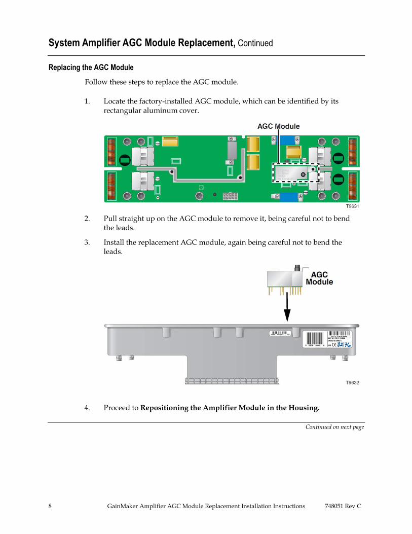
1. Locate the factory-installed AGC module, which can be identified by its rectangular aluminum cover.
2. Pull straight up on the AGC module to remove it, being careful not to bend the leads.
3. Install the replacement AGC module, again being careful not to bend the leads.
4. Proceed to Repositioning the Amplifier Module in the Housing.
Continued on next page
748051 Rev C GainMaker Amplifier AGC Module Replacement Installation Instructions 9
System Amplifier AGC Module Replacement, Continued
Repositioning the Amplifier Module in the Housing
Follow these steps to reposition the amplifier module in the housing.
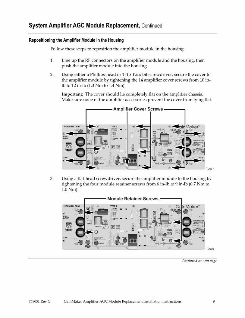
1. Line up the RF connectors on the amplifier module and the housing, then push the amplifier module into the housing.
2. Using either a Phillips-head or T-15 Torx bit screwdriver, secure the cover to the amplifier module by tightening the 14 amplifier cover screws from 10 in-lb to 12 in-lb (1.3 Nm to 1.4 Nm).
Important: The cover should lie completely flat on the amplifier chassis. Make sure none of the amplifier accessories prevent the cover from lying flat.
3. Using a flat-head screwdriver, secure the amplifier module to the housing by tightening the four module retainer screws from 6 in-lb to 9 in-lb (0.7 Nm to 1.0 Nm).
Continued on next page
10 GainMaker Amplifier AGC Module Replacement Installation Instructions 748051 Rev C
System Amplifier AGC Module Replacement, Continued
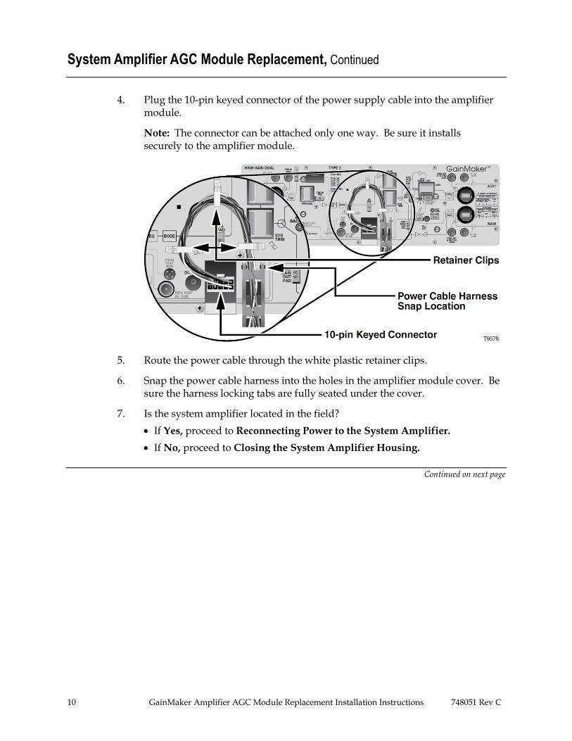
4. Plug the 10-pin keyed connector of the power supply cable into the amplifier module.
Note: The connector can be attached only one way. Be sure it installs securely to the amplifier module.
5. Route the power cable through the white plastic retainer clips.
6. Snap the power cable harness into the holes in the amplifier module cover. Be sure the harness locking tabs are fully seated under the cover.
7. Is the system amplifier located in the field?
If Yes, proceed to Reconnecting Power to the System Amplifier.
If No, proceed to Closing the System Amplifier Housing.
Continued on next page
748051 Rev C GainMaker Amplifier AGC Module Replacement Installation Instructions 11
System Amplifier AGC Module Replacement, Continued
Reconnecting Power to the System Amplifier
These instructions explain how to reconnect the power to a system amplifier located in the field. If your system amplifier is not located in the field, proceed to Closing the System Amplifier Housing.
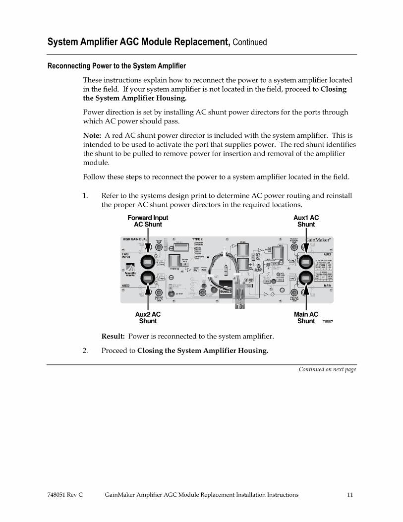
Power direction is set by installing AC shunt power directors for the ports through which AC power should pass.
Note: A red AC shunt power director is included with the system amplifier. This is intended to be used to activate the port that supplies power. The red shunt identifies the shunt to be pulled to remove power for insertion and removal of the amplifier module.
Follow these steps to reconnect the power to a system amplifier located in the field.
1. Refer to the systems design print to determine AC power routing and reinstall the proper AC shunt power directors in the required locations.
Result: Power is reconnected to the system amplifier.
2. Proceed to Closing the System Amplifier Housing.
Continued on next page
12 GainMaker Amplifier AGC Module Replacement Installation Instructions 748051 Rev C
System Amplifier AGC Module Replacement, Continued
Closing the System Amplifier Housing
Follow these steps to close the system amplifier housing.
1. Inspect the housing gasket and all mating surfaces. Wipe off any dirt and debris.
CAUTION:
Avoid moisture damage and RF leakage! Follow steps 2 and 3 exactly as explained below to ensure a proper seal.
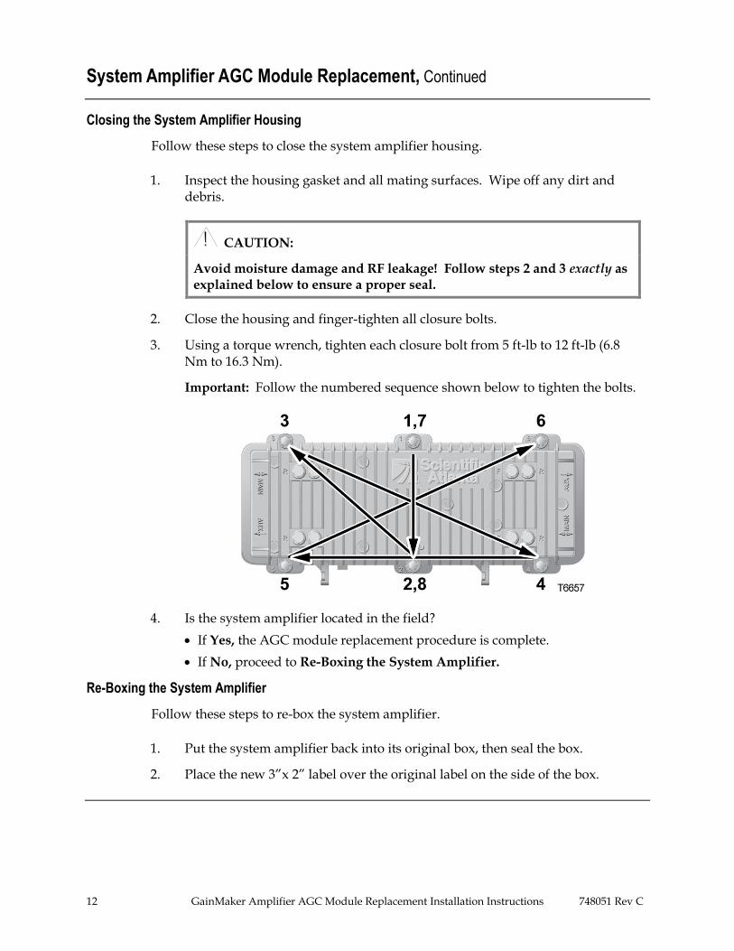
2. Close the housing and finger-tighten all closure bolts.
3. Using a torque wrench, tighten each closure bolt from 5 ft-lb to 12 ft-lb (6.8 Nm to 16.3 Nm).
Important: Follow the numbered sequence shown below to tighten the bolts.
4. Is the system amplifier located in the field?
If Yes, the AGC module replacement procedure is complete.
If No, proceed to Re-Boxing the System Amplifier.
Re-Boxing the System Amplifier
Follow these steps to re-box the system amplifier.
1. Put the system amplifier back into its original box, then seal the box.
2. Place the new 3”x 2” label over the original label on the side of the box.
748051 Rev C GainMaker Amplifier AGC Module Replacement Installation Instructions 13
Line Extender AGC Module Replacement
Introduction
The steps required to replace an AGC module in a line extender vary, depending on whether or not the line extender is located in the field.
The following is a list of all possible steps:
Disconnecting power from the line extender
Removing the amplifier module from the housing
Replacing the AGC module
Repositioning the amplifier module in the housing
Reconnecting power to the line extender
Closing the line extender housing
Re-boxing the line extender
Required Tools and Equipment
Before you start, make sure you have the following tools and equipment:
Replacement AGC module (provided with these instructions)
Torque wrench with a 1/2-in. socket
Flat-head screwdriver
Screwdriver appropriate for the type of screws on the amplifier module cover
Phillips-head screwdriver
T-15 Torx bit screwdriver
Two product labels (provided with these instructions)
3”x 1” amplifier chassis label
3”x 2” box label (for line extenders not located in the field)
Continued on next page
14 GainMaker Amplifier AGC Module Replacement Installation Instructions 748051 Rev C
Line Extender AGC Module Replacement, Continued
Disconnecting Power From the Line Extender
These instructions explain how to disconnect the power from a line extender located in the field. This step is required before the amplifier module can be removed from the housing.
If your line extender is not located in the field, proceed to Removing the Amplifier Module From the Housing.
WARNING!
Protect yourself from electric shock and your system from damage! Take precautions when working with this equipment. Certain components can deliver an electrical shock or cause burns. Disconnect the power before removing the amplifier module from the housing.
CAUTION:
RF connectors and housing seizure assemblies can be damaged if AC shunt power directors are not removed from the line extender before removing the amplifier module from the housing.
Follow these steps to disconnect the power from a line extender located in the field.
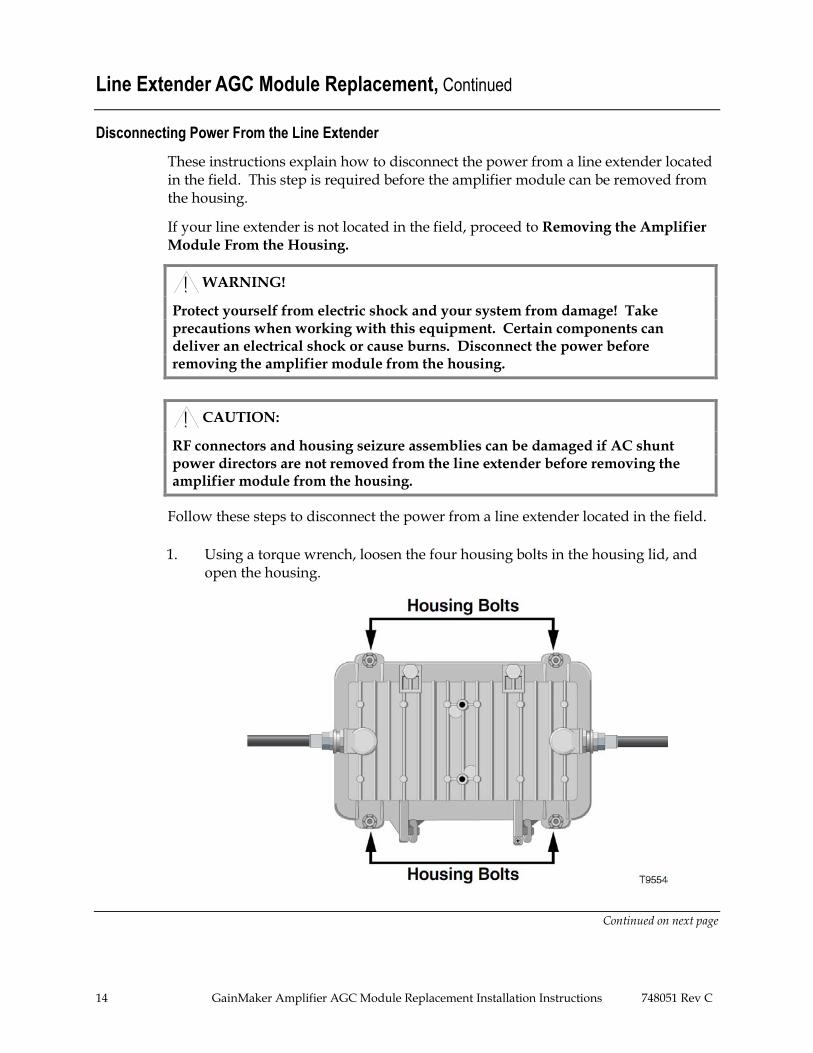
1. Using a torque wrench, loosen the four housing bolts in the housing lid, and open the housing.
Continued on next page
748051 Rev C GainMaker Amplifier AGC Module Replacement Installation Instructions 15
Line Extender AGC Module Replacement, Continued
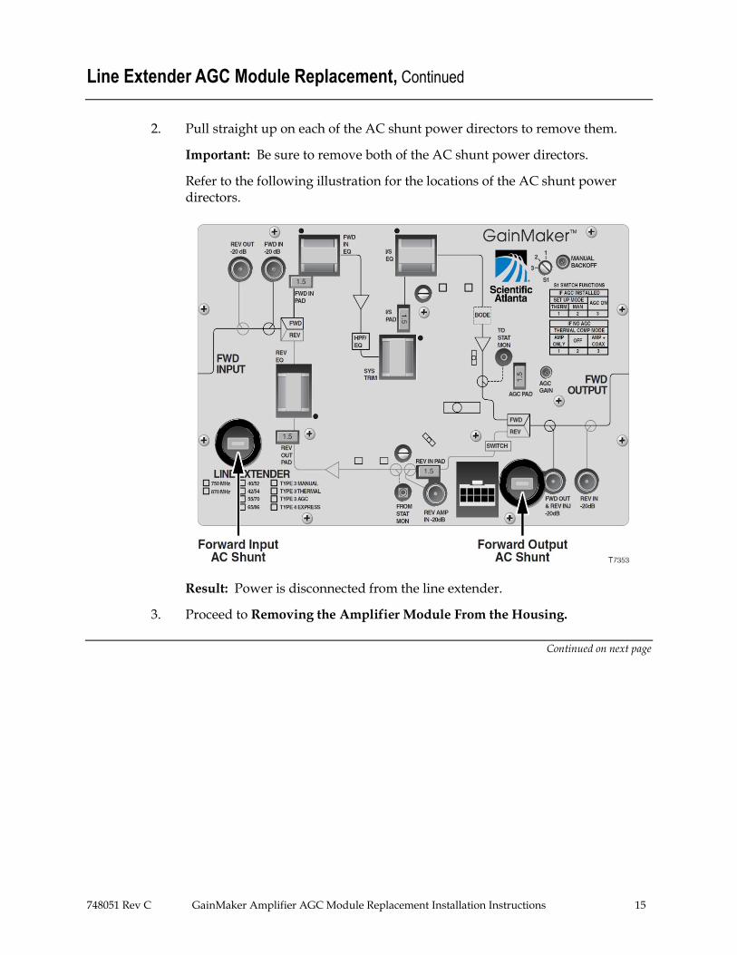
2. Pull straight up on each of the AC shunt power directors to remove them.
Important: Be sure to remove both of the AC shunt power directors.
Refer to the following illustration for the locations of the AC shunt power directors.
Result: Power is disconnected from the line extender.
3. Proceed to Removing the Amplifier Module From the Housing.
Continued on next page
16 GainMaker Amplifier AGC Module Replacement Installation Instructions 748051 Rev C
Line Extender AGC Module Replacement, Continued
Removing the Amplifier Module From the Housing
Important: If the line extender is located in the field, refer to Disconnecting Power
From the Line Extender earlier in this section before removing the amplifier module from the housing.
Follow these steps to remove the amplifier module from the housing.
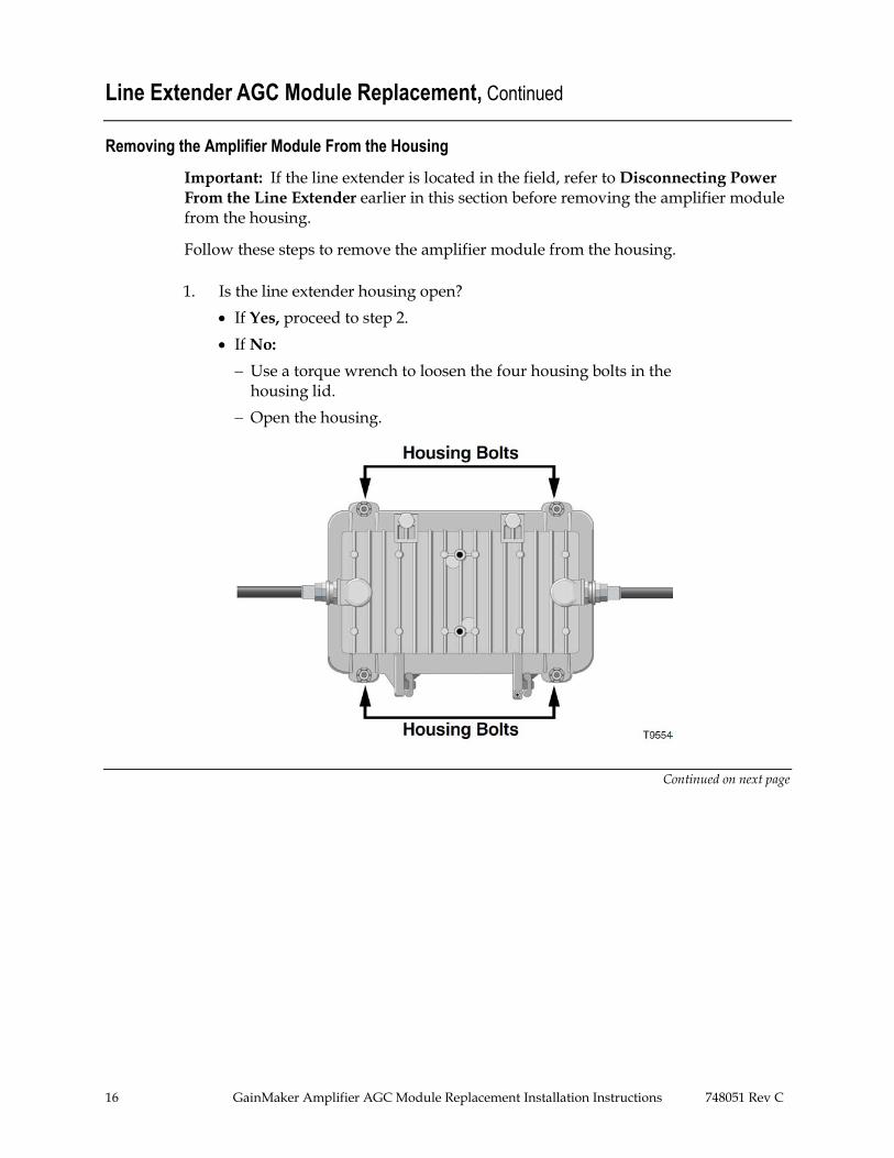
1. Is the line extender housing open?
If Yes, proceed to step 2.
If No:
Use a torque wrench to loosen the four housing bolts in the housing lid.
Open the housing.
Continued on next page
748051 Rev C GainMaker Amplifier AGC Module Replacement Installation Instructions 17
Line Extender AGC Module Replacement, Continued
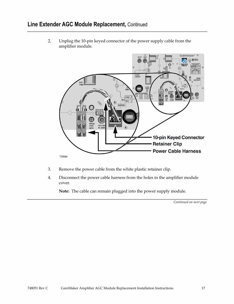
2. Unplug the 10-pin keyed connector of the power supply cable from the amplifier module.
3. Remove the power cable from the white plastic retainer clip.
4. Disconnect the power cable harness from the holes in the amplifier module cover.
Note: The cable can remain plugged into the power supply module.
Continued on next page
18 GainMaker Amplifier AGC Module Replacement Installation Instructions 748051 Rev C
Line Extender AGC Module Replacement, Continued
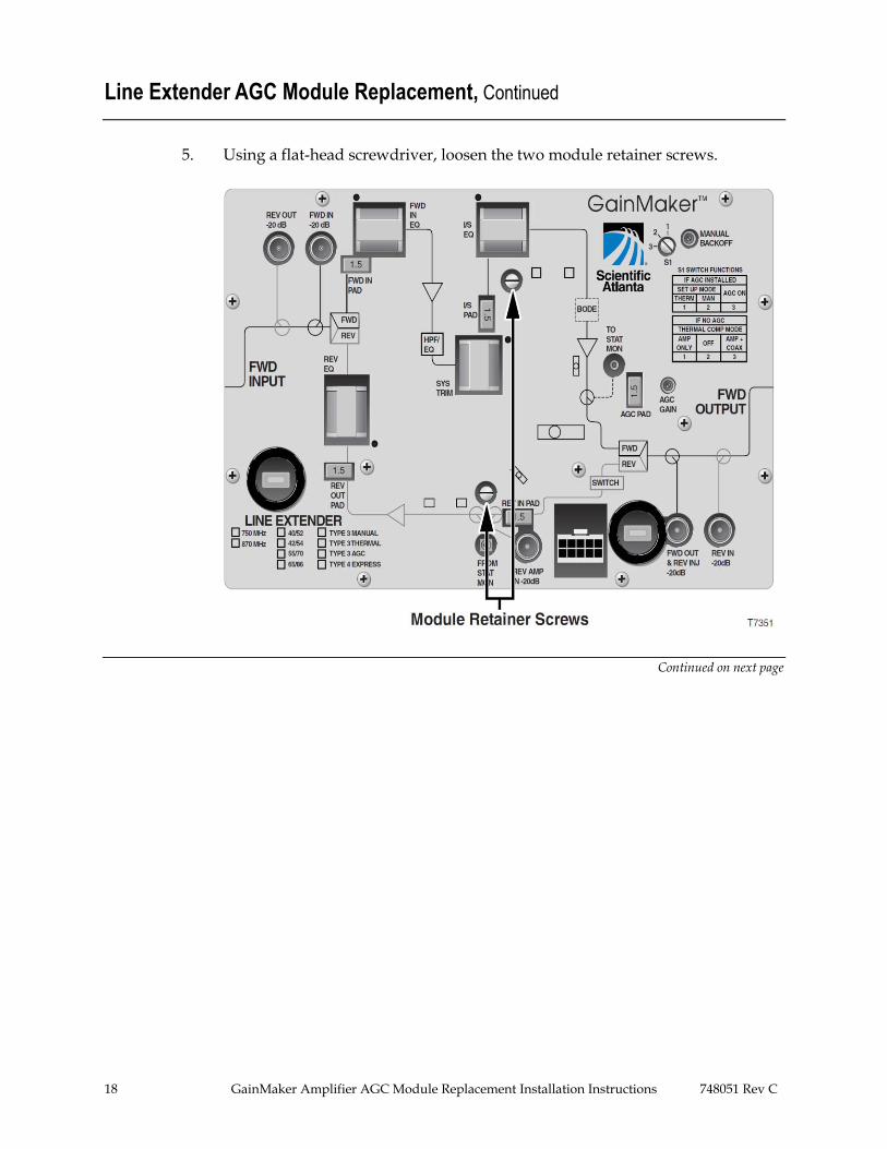
5. Using a flat-head screwdriver, loosen the two module retainer screws.
Continued on next page
748051 Rev C GainMaker Amplifier AGC Module Replacement Installation Instructions 19
Line Extender AGC Module Replacement, Continued
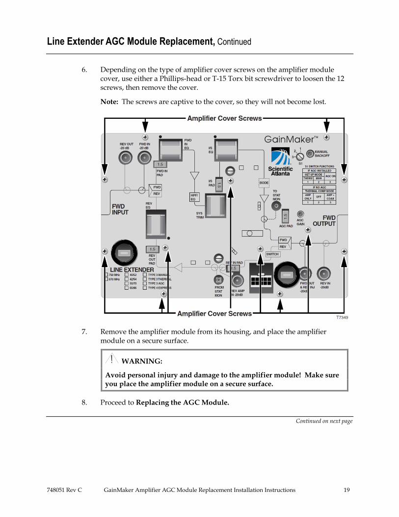
6. Depending on the type of amplifier cover screws on the amplifier module cover, use either a Phillips-head or T-15 Torx bit screwdriver to loosen the 12 screws, then remove the cover.
Note: The screws are captive to the cover, so they will not become lost.
7. Remove the amplifier module from its housing, and place the amplifier module on a secure surface.
WARNING:
Avoid personal injury and damage to the amplifier module! Make sure you place the amplifier module on a secure surface.
8. Proceed to Replacing the AGC Module.
Continued on next page
20 GainMaker Amplifier AGC Module Replacement Installation Instructions 748051 Rev C
Line Extender AGC Module Replacement, Continued
Replacing the AGC Module
Follow these steps to replace the AGC module.
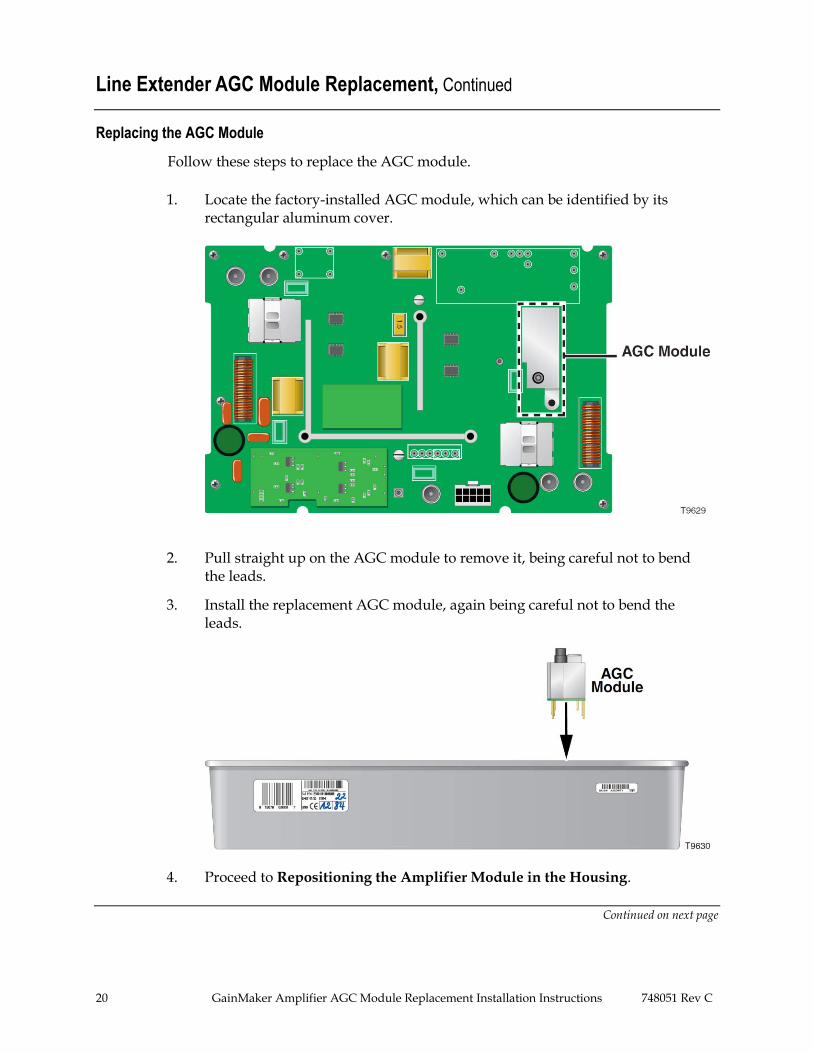
1. Locate the factory-installed AGC module, which can be identified by its rectangular aluminum cover.
2. Pull straight up on the AGC module to remove it, being careful not to bend the leads.
3. Install the replacement AGC module, again being careful not to bend the leads.
4. Proceed to Repositioning the Amplifier Module in the Housing.
Continued on next page
748051 Rev C GainMaker Amplifier AGC Module Replacement Installation Instructions 21
Line Extender AGC Module Replacement, Continued
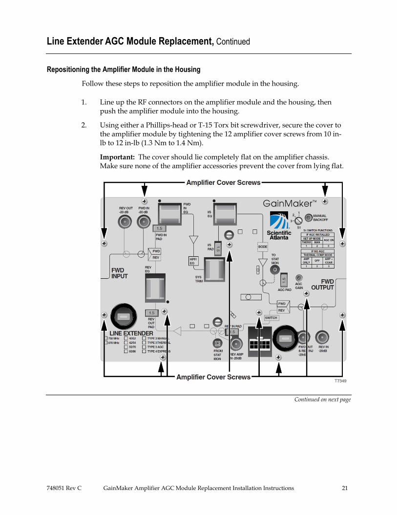
Repositioning the Amplifier Module in the Housing
Follow these steps to reposition the amplifier module in the housing.
1. Line up the RF connectors on the amplifier module and the housing, then push the amplifier module into the housing.
2. Using either a Phillips-head or T-15 Torx bit screwdriver, secure the cover to the amplifier module by tightening the 12 amplifier cover screws from 10 in-lb to 12 in-lb (1.3 Nm to 1.4 Nm).
Important: The cover should lie completely flat on the amplifier chassis. Make sure none of the amplifier accessories prevent the cover from lying flat.
Continued on next page
22 GainMaker Amplifier AGC Module Replacement Installation Instructions 748051 Rev C
Line Extender AGC Module Replacement, Continued
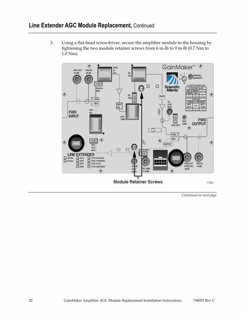
3. Using a flat-head screwdriver, secure the amplifier module to the housing by tightening the two module retainer screws from 6 in-lb to 9 in-lb (0.7 Nm to 1.0 Nm).
Continued on next page
748051 Rev C GainMaker Amplifier AGC Module Replacement Installation Instructions 23
Line Extender AGC Module Replacement, Continued
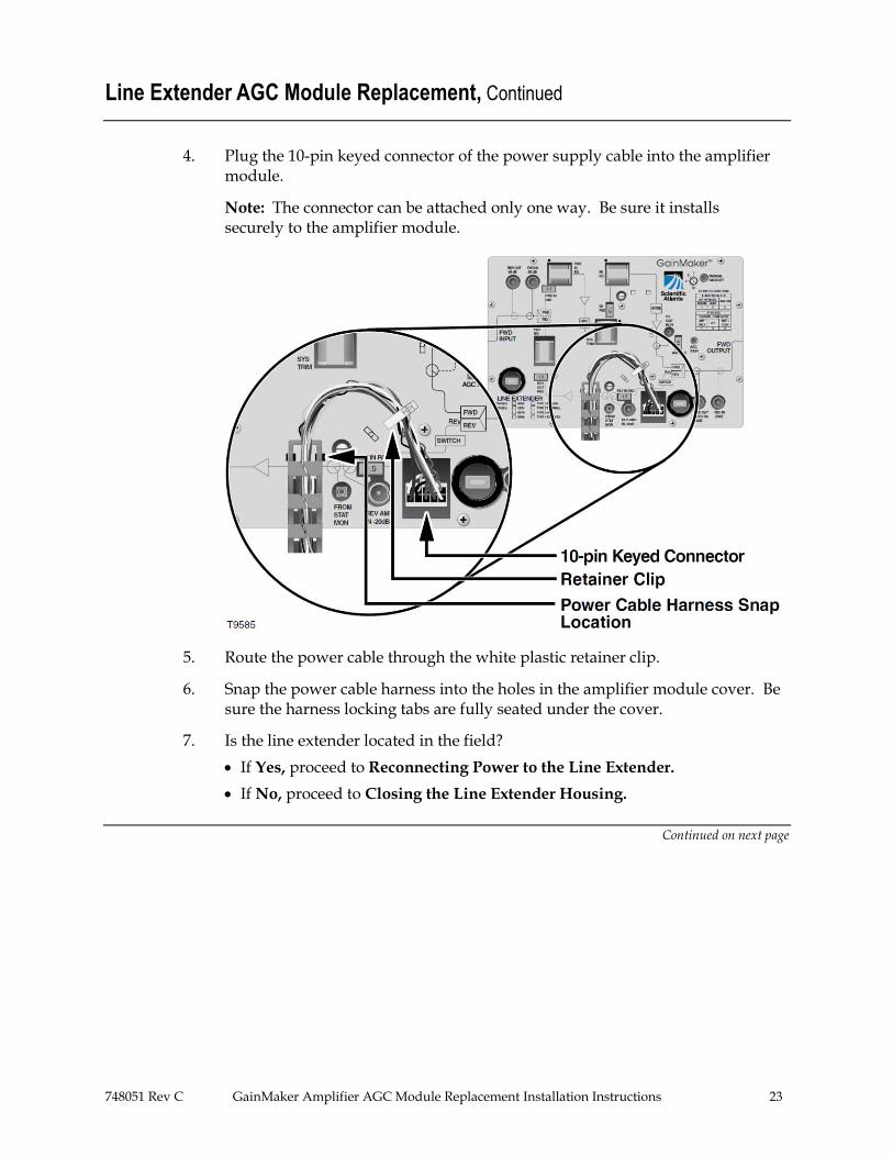
4. Plug the 10-pin keyed connector of the power supply cable into the amplifier module.
Note: The connector can be attached only one way. Be sure it installs securely to the amplifier module.
5. Route the power cable through the white plastic retainer clip.
6. Snap the power cable harness into the holes in the amplifier module cover. Be sure the harness locking tabs are fully seated under the cover.
7. Is the line extender located in the field?
If Yes, proceed to Reconnecting Power to the Line Extender.
If No, proceed to Closing the Line Extender Housing.
Continued on next page
24 GainMaker Amplifier AGC Module Replacement Installation Instructions 748051 Rev C
Line Extender AGC Module Replacement, Continued
Reconnecting Power to the Line Extender
These instructions explain how to reconnect the power to a line extender located in the field. If your line extender is not located in the field, proceed to Closing the Line Extender Housing.
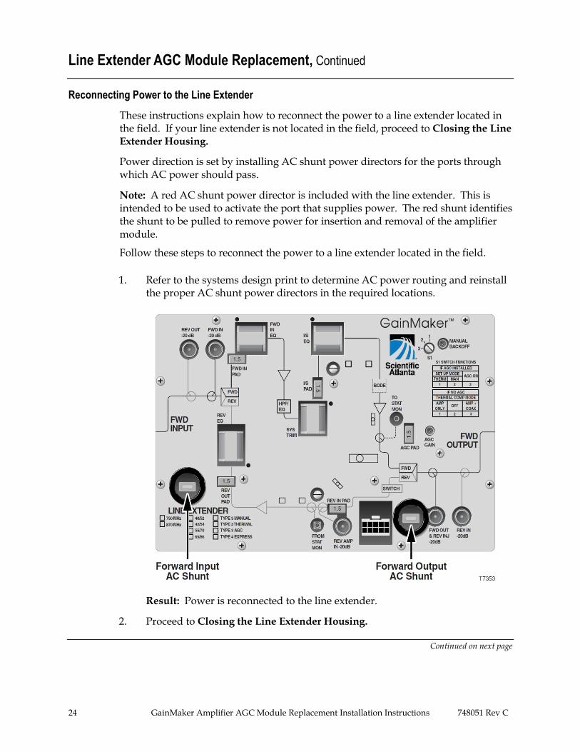
Power direction is set by installing AC shunt power directors for the ports through which AC power should pass.
Note: A red AC shunt power director is included with the line extender. This is intended to be used to activate the port that supplies power. The red shunt identifies the shunt to be pulled to remove power for insertion and removal of the amplifier module.
Follow these steps to reconnect the power to a line extender located in the field.
1. Refer to the systems design print to determine AC power routing and reinstall the proper AC shunt power directors in the required locations.
Result: Power is reconnected to the line extender.
2. Proceed to Closing the Line Extender Housing.
Continued on next page
748051 Rev C GainMaker Amplifier AGC Module Replacement Installation Instructions 25
Line Extender AGC Module Replacement, Continued
Closing the Line Extender Housing
Follow these steps to close the line extender housing.
1. Inspect the housing gasket and all mating surfaces. Wipe off any dirt and debris.
CAUTION:
Avoid moisture damage and RF leakage! Follow steps 2 and 3 exactly as explained below to ensure a proper seal.
2. Close the housing and finger-tighten all closure bolts.
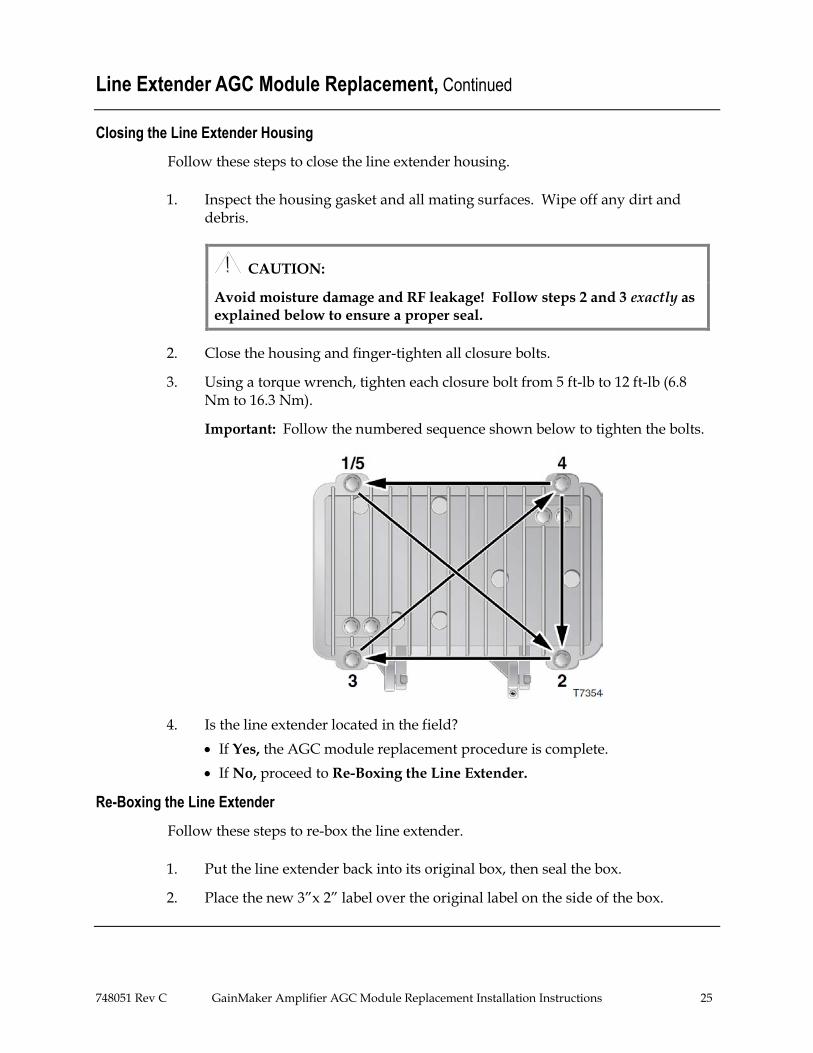
3. Using a torque wrench, tighten each closure bolt from 5 ft-lb to 12 ft-lb (6.8 Nm to 16.3 Nm).
Important: Follow the numbered sequence shown below to tighten the bolts.
4. Is the line extender located in the field?
If Yes, the AGC module replacement procedure is complete.
If No, proceed to Re-Boxing the Line Extender.
Re-Boxing the Line Extender
Follow these steps to re-box the line extender.
1. Put the line extender back into its original box, then seal the box.
2. Place the new 3”x 2” label over the original label on the side of the box.
26 GainMaker Amplifier AGC Module Replacement Installation Instructions 748051 Rev C
For Information
If You Have Questions
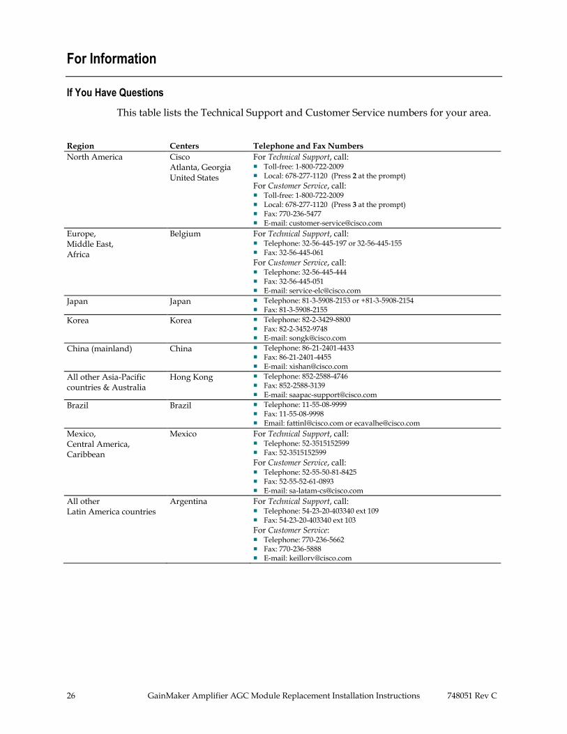
This table lists the Technical Support and Customer Service numbers for your area.
Region Centers Telephone and Fax Numbers
North America Cisco Atlanta, Georgia United States
For Technical Support, call: Toll-free: 1-800-722-2009 Local: 678-277-1120 (Press 2 at the prompt)
For Customer Service, call: Toll-free: 1-800-722-2009 Local: 678-277-1120 (Press 3 at the prompt) Fax: 770-236-5477 E-mail: [email protected]
Europe, Middle East, Africa
Belgium For Technical Support, call: Telephone: 32-56-445-197 or 32-56-445-155 Fax: 32-56-445-061
For Customer Service, call: Telephone: 32-56-445-444 Fax: 32-56-445-051 E-mail: [email protected]
Japan Japan Telephone: 81-3-5908-2153 or +81-3-5908-2154 Fax: 81-3-5908-2155
Korea Korea Telephone: 82-2-3429-8800 Fax: 82-2-3452-9748 E-mail: [email protected]
China (mainland) China Telephone: 86-21-2401-4433 Fax: 86-21-2401-4455 E-mail: [email protected]
All other Asia-Pacific countries & Australia
Hong Kong Telephone: 852-2588-4746 Fax: 852-2588-3139 E-mail: [email protected]
Brazil Brazil Telephone: 11-55-08-9999 Fax: 11-55-08-9998 Email: [email protected] or [email protected]
Mexico, Central America, Caribbean
Mexico For Technical Support, call: Telephone: 52-3515152599 Fax: 52-3515152599
For Customer Service, call: Telephone: 52-55-50-81-8425 Fax: 52-55-52-61-0893 E-mail: [email protected]
All other Latin America countries
Argentina For Technical Support, call: Telephone: 54-23-20-403340 ext 109 Fax: 54-23-20-403340 ext 103
For Customer Service: Telephone: 770-236-5662 Fax: 770-236-5888 E-mail: [email protected]

748051 Rev C GainMaker Amplifier AGC Module Replacement Installation Instructions 27
Cisco Systems, Inc. 5030 Sugarloaf Parkway, Box 465447 Lawrenceville, GA 30042
678 277-1120 800 722-2009
www.cisco.com
Cisco and the Cisco logo are trademarks or registered trademarks of Cisco Systems, Inc. and/or its affiliates in the U.S. and other countries. A listing of Cisco’s trademarks can be found at www.cisco.com/go/trademarks. Third party trademarks mentioned are the property of their respective owners. The use of the word partner does not imply a partnership relationship between Cisco and any other company.(1007R) Product and service availability are subject to change without notice.
© 2001, 2008, 2011 Cisco and its affiliates. All rights reserved. Printed in USA January 2011 Part Number 748051 Rev C