GAIL INDIA LIMITED CONSTRUCTION OF STEEL PIPELINE AND … - INSTRUMENTATION_14.pdf ·...
219
www.lyonsengineers.com GAIL INDIA LIMITED CONSTRUCTION OF STEEL PIPELINE AND ASSOCIATED FACILITIES ON ANNUAL RATE CONTRACT BASIS FOR WESTERN REGION VOLUME II OF II (TECHNICAL) – H INSTRUMENTATION E-TENDER REF : 8000014263 (BID DOCUMENT NO - 034/LEPL/GAIL/04-R0) Lyons Engineering Pvt. Ltd.
Transcript of GAIL INDIA LIMITED CONSTRUCTION OF STEEL PIPELINE AND … - INSTRUMENTATION_14.pdf ·...

www.lyonsengineers.com
GAIL INDIA LIMITED
CONSTRUCTION OF STEEL PIPELINE AND ASSOCIATED FACILITIES
ON ANNUAL RATE CONTRACT BASIS FOR WESTERN REGION
VOLUME II OF II (TECHNICAL) – H
INSTRUMENTATION
E-TENDER REF : 8000014263
(BID DOCUMENT NO - 034/LEPL/GAIL/04-R0)
Lyons Engineering Pvt. Ltd.

PMC: CLIENT:
H
Sr. No. Description Document / Drawing No. Rev. No.
1 Instrumentation Design Basis GAIL-STD-IN-DOC-DB-001 0
2 Standard specification for Pressure Gauges. GAIL-STD-IN-DOC-TS-001 03 Standard specification for Pressure Safety Valves. GAIL-STD-IN-DOC-TS-002 04 Standard specifications for Electronic Transmitters GAIL-STD-IN-DOC-TS-003 05 Standard specification for RTDs and thermowell GAIL-STD-IN-DOC-TS-004 06 Standard specifications for Instrument cables. GAIL-STD-IN-DOC-TS-005 0
7Standard specifications for Junction Boxes and cable Glands.
GAIL-STD-IN-DOC-TS-006 0
8 Standard specifications for instrument tube fittings GAIL-STD-IN-DOC-TS-007 09 Standard specifications for instrument tubing GAIL-STD-IN-DOC-TS-008 010 Standard Specification for Instrument Valve & Manifold GAIL-STD-IN-DOC-TS-009 0
11 Standard specifications for Fire & Gas Detection System GAIL-STD-IN-DOC-TS-011 0
12 Standard specifications for control Panels GAIL-STD-IN-DOC-TS-012 013 Standard specifications for Pig Signalers GAIL-STD-IN-DOC-TS-013 0
14 Datasheet for Pressure Transmitter GAIL-STD-IN-DOC-DS-001 015 Datasheet for Temperature Transmitter GAIL-STD-IN-DOC-DS-002 0
16Datasheet for Temperature Element (RTD) with Thermowell
GAIL-STD-IN-DOC-DS-003 0
17 Datasheet for Gas Detector GAIL-STD-IN-DOC-DS-004 018 Datasheet for Pressure Gauges GAIL-STD-IN-DOC-DS-005 019 Datasheet for Temperature Gauges GAIL-STD-IN-DOC-DS-006 020 Datasheet for Pressure Safety Valve GAIL-STD-IN-DOC-DS-007 0
21Datasheet for Scrapper/Pig Signaller/detector- Intrusive Type
GAIL-STD-IN-DOC-DS-008 0
22 Datasheet for GOOV GAIL-STD-IN-DOC-DS-009 0
23 QAP for Temperature Transmitters GAIL-STD-IN-DOC-QAP-001 024 QAP for RTDs and Thermowells GAIL-STD-IN-DOC-QAP-002 025 QAP for Pressure Transmitters GAIL-STD-IN-DOC-QAP-003 026 QAP for Pressure Gauges GAIL-STD-IN-DOC-QAP-004 027 QAP for Temperature Gauges GAIL-STD-IN-DOC-QAP-005 028 QAP for Instrument Cables GAIL-STD-IN-DOC-QAP-006 029 QAP for Pressure Safety Valves GAIL-STD-IN-DOC-QAP-007 030 QAP for Pig Signaller GAIL-STD-IN-DOC-QAP-008 031 QAP for GAS detector GAIL-STD-IN-DOC-QAP-009 032 QAP for Gas over Oil Actuators GAIL-STD-IN-DOC-QAP-010 0
33Instrument Connection on Vessels, Standpipes and Tanks
STD-ENG-IN-DWG-TP-001 0
34 Drain for Single Line STD-ENG-IN-DWG-TP-002 0
35Pressure Instrument Installation Scope of Work
STD-ENG-IN-DWG-TP-003 0
36 Flow Meter Installation Scope of Work STD-ENG-IN-DWG-TP-004 0
37Thermowell Installation Scope of Work
STD-ENG-IN-DWG-TP-005 0
38Instrument Connection on Vessel, Standpipes and Tanks
STD-ENG-IN-DWG-TP-006 0
39Meter Runs – Piping Connections D – D/2 Taps
STD-ENG-IN-DWG-TP-007 0
40Meter Runs – Piping Connections Pipe (2 ½ D – 8d) Taps
STD-ENG-IN-DWG-TP-008 0
41 Thermowell STD-ENG-IN-DWG-TP-009 0
42Thermocouple / RTD Assembly With Thermowell
STD-ENG-IN-DWG-TP-010 0
43Symbol for Instrument Location Drawings
STD-ENG-IN-DWG-TP-011 0
44Instrument Support Single Instrument
STD-ENG-IN-DWG-TP-012 0
45Instrument Support Two Instruments
STD-ENG-IN-DWG-TP-013 0
46Support Details for Junction Boxes
STD-ENG-IN-DWG-TP-014 0
47Fabricated Canopy for Instruments
STD-ENG-IN-DWG-TP-015 0
48Perforated Tray Supports and Cables Clamping Details
STD-ENG-IN-DWG-TP-016 0
49Pressure Gauge Liquid / Gas Service
STD-ENG-IN-DWG-TP-017 0
50 Purge for Instrument Single Line STD-ENG-IN-DWG-TP-018 051 Purge for Instrument Double Line STD-ENG-IN-DWG-TP-019 0
DATASHEET FOR INSTRUMENT
QAP FOR INSTRUMENT
STANDARD TYPICAL DRAWING
Instrumentation
Document Control Index
INSTRUMENTATION
STANDARD SPECIFICATION FOR INSTRUMENTS
Page 1 of 1

GAIL INDIA LIMITED
INSTRUMENTATION DESIGN BASIS
GAIL-STD-IN-DOC-DB-001
0 15.01.2019 Issued for Approval RKS UNU UNU
Rev Date Purpose Prepared
By Checked
By Approved
By

INSTRUMENTATION DESIGN BASIS
Document No. Rev
GIGL‐ENG‐IN‐DOC‐DB‐001 1
SHEET 2 of 30
TABLE OF CONTENTS
1.0 Introduction‐‐‐‐‐‐‐‐‐‐‐‐‐‐‐‐‐‐‐‐‐‐‐‐‐‐‐‐‐‐‐‐‐‐‐‐‐‐‐‐‐‐‐‐‐‐‐‐‐‐‐‐‐‐‐‐‐‐‐‐‐‐‐‐‐‐‐‐‐‐‐‐‐‐‐‐‐‐‐‐‐‐‐‐‐‐‐‐‐‐‐‐‐03
2.0 Applicable Codes, Standards, Abbreviations and Definitions‐‐‐‐‐‐‐‐‐‐‐‐‐‐‐‐‐‐‐‐‐‐‐‐‐‐‐‐‐‐03
3.0 General Design Criteria‐‐‐‐‐‐‐‐‐‐‐‐‐‐‐‐‐‐‐‐‐‐‐‐‐‐‐‐‐‐‐‐‐‐‐‐‐‐‐‐‐‐‐‐‐‐‐‐‐‐‐‐‐‐‐‐‐‐‐‐‐‐‐‐‐‐‐‐‐‐‐‐‐‐‐‐‐‐‐09
4.0 Type of Instrument Protection‐‐‐‐‐‐‐‐‐‐‐‐‐‐‐‐‐‐‐‐‐‐‐‐‐‐‐‐‐‐‐‐‐‐‐‐‐‐‐‐‐‐‐‐‐‐‐‐‐‐‐‐‐‐‐‐‐‐‐‐‐‐‐‐‐‐‐‐‐12
5.0 Certification Requirements‐‐‐‐‐‐‐‐‐‐‐‐‐‐‐‐‐‐‐‐‐‐‐‐‐‐‐‐‐‐‐‐‐‐‐‐‐‐‐‐‐‐‐‐‐‐‐‐‐‐‐‐‐‐‐‐‐‐‐‐‐‐‐‐‐‐‐‐‐‐‐‐‐12
6.0 Units of Measurements‐‐‐‐‐‐‐‐‐‐‐‐‐‐‐‐‐‐‐‐‐‐‐‐‐‐‐‐‐‐‐‐‐‐‐‐‐‐‐‐‐‐‐‐‐‐‐‐‐‐‐‐‐‐‐‐‐‐‐‐‐‐‐‐‐‐‐‐‐‐‐‐‐‐‐‐‐‐12
7.0 Utility Requirements‐‐‐‐‐‐‐‐‐‐‐‐‐‐‐‐‐‐‐‐‐‐‐‐‐‐‐‐‐‐‐‐‐‐‐‐‐‐‐‐‐‐‐‐‐‐‐‐‐‐‐‐‐‐‐‐‐‐‐‐‐‐‐‐‐‐‐‐‐‐‐‐‐‐‐‐‐‐‐‐‐13
8.0 Process and Electrical Connections‐‐‐‐‐‐‐‐‐‐‐‐‐‐‐‐‐‐‐‐‐‐‐‐‐‐‐‐‐‐‐‐‐‐‐‐‐‐‐‐‐‐‐‐‐‐‐‐‐‐‐‐‐‐‐‐‐‐‐‐‐‐‐14
9.0 Material Selection Philosophy‐‐‐‐‐‐‐‐‐‐‐‐‐‐‐‐‐‐‐‐‐‐‐‐‐‐‐‐‐‐‐‐‐‐‐‐‐‐‐‐‐‐‐‐‐‐‐‐‐‐‐‐‐‐‐‐‐‐‐‐‐‐‐‐‐‐‐‐‐14
10.0 Instrumentation‐‐‐‐‐‐‐‐‐‐‐‐‐‐‐‐‐‐‐‐‐‐‐‐‐‐‐‐‐‐‐‐‐‐‐‐‐‐‐‐‐‐‐‐‐‐‐‐‐‐‐‐‐‐‐‐‐‐‐‐‐‐‐‐‐‐‐‐‐‐‐‐‐‐‐‐‐‐‐‐‐‐‐‐‐‐‐15
10.1 Pressure Instruments‐‐‐‐‐‐‐‐‐‐‐‐‐‐‐‐‐‐‐‐‐‐‐‐‐‐‐‐‐‐‐‐‐‐‐‐‐‐‐‐‐‐‐‐‐‐‐‐‐‐‐‐‐‐‐‐‐‐‐‐‐‐‐‐‐‐‐‐‐‐‐‐‐‐‐‐‐‐‐‐15
10.2 Temperature Instruments‐‐‐‐‐‐‐‐‐‐‐‐‐‐‐‐‐‐‐‐‐‐‐‐‐‐‐‐‐‐‐‐‐‐‐‐‐‐‐‐‐‐‐‐‐‐‐‐‐‐‐‐‐‐‐‐‐‐‐‐‐‐‐‐‐‐‐‐‐‐‐‐‐‐17
11.0 Gas Over Oil Actuators (GOOV)‐‐‐‐‐‐‐‐‐‐‐‐‐‐‐‐‐‐‐‐‐‐‐‐‐‐‐‐‐‐‐‐‐‐‐‐‐‐‐‐‐‐‐‐‐‐‐‐‐‐‐‐‐‐‐‐‐‐‐‐‐‐‐‐‐‐‐18
12.0 Control Panel‐‐‐‐‐‐‐‐‐‐‐‐‐‐‐‐‐‐‐‐‐‐‐‐‐‐‐‐‐‐‐‐‐‐‐‐‐‐‐‐‐‐‐‐‐‐‐‐‐‐‐‐‐‐‐‐‐‐‐‐‐‐‐‐‐‐‐‐‐‐‐‐‐‐‐‐‐‐‐‐‐‐‐‐‐‐‐‐‐‐‐19
13.0 Pressure Safety Valve (PSV)‐‐‐‐‐‐‐‐‐‐‐‐‐‐‐‐‐‐‐‐‐‐‐‐‐‐‐‐‐‐‐‐‐‐‐‐‐‐‐‐‐‐‐‐‐‐‐‐‐‐‐‐‐‐‐‐‐‐‐‐‐‐‐‐‐‐‐‐‐‐‐‐20
14.0 Control Panel‐‐‐‐‐‐‐‐‐‐‐‐‐‐‐‐‐‐‐‐‐‐‐‐‐‐‐‐‐‐‐‐‐‐‐‐‐‐‐‐‐‐‐‐‐‐‐‐‐‐‐‐‐‐‐‐‐‐‐‐‐‐‐‐‐‐‐‐‐‐‐‐‐‐‐‐‐‐‐‐‐‐‐‐‐‐‐‐‐‐‐20
15.0 Gas Detection System (GDS)‐‐‐‐‐‐‐‐‐‐‐‐‐‐‐‐‐‐‐‐‐‐‐‐‐‐‐‐‐‐‐‐‐‐‐‐‐‐‐‐‐‐‐‐‐‐‐‐‐‐‐‐‐‐‐‐‐‐‐‐‐‐‐‐‐‐‐‐‐‐‐21
16.0 Fire Alarm Control Panel (FACP)‐‐‐‐‐‐‐‐‐‐‐‐‐‐‐‐‐‐‐‐‐‐‐‐‐‐‐‐‐‐‐‐‐‐‐‐‐‐‐‐‐‐‐‐‐‐‐‐‐‐‐‐‐‐‐‐‐‐‐‐‐‐‐‐‐‐23
17.0 Instrument Cabling and Wiring‐‐‐‐‐‐‐‐‐‐‐‐‐‐‐‐‐‐‐‐‐‐‐‐‐‐‐‐‐‐‐‐‐‐‐‐‐‐‐‐‐‐‐‐‐‐‐‐‐‐‐‐‐‐‐‐‐‐‐‐‐‐‐‐‐‐‐‐23
18.0 Junction Box‐‐‐‐‐‐‐‐‐‐‐‐‐‐‐‐‐‐‐‐‐‐‐‐‐‐‐‐‐‐‐‐‐‐‐‐‐‐‐‐‐‐‐‐‐‐‐‐‐‐‐‐‐‐‐‐‐‐‐‐‐‐‐‐‐‐‐‐‐‐‐‐‐‐‐‐‐‐‐‐‐‐‐‐‐‐‐‐‐‐‐‐23
19.0 Others‐‐‐‐‐‐‐‐‐‐‐‐‐‐‐‐‐‐‐‐‐‐‐‐‐‐‐‐‐‐‐‐‐‐‐‐‐‐‐‐‐‐‐‐‐‐‐‐‐‐‐‐‐‐‐‐‐‐‐‐‐‐‐‐‐‐‐‐‐‐‐‐‐‐‐‐‐‐‐‐‐‐‐‐‐‐‐‐‐‐‐‐‐‐‐‐‐‐‐‐24
20.0 General‐‐‐‐‐‐‐‐‐‐‐‐‐‐‐‐‐‐‐‐‐‐‐‐‐‐‐‐‐‐‐‐‐‐‐‐‐‐‐‐‐‐‐‐‐‐‐‐‐‐‐‐‐‐‐‐‐‐‐‐‐‐‐‐‐‐‐‐‐‐‐‐‐‐‐‐‐‐‐‐‐‐‐‐‐‐‐‐‐‐‐‐‐‐‐‐‐‐24
21.0 Technical Design Documents‐‐‐‐‐‐‐‐‐‐‐‐‐‐‐‐‐‐‐‐‐‐‐‐‐‐‐‐‐‐‐‐‐‐‐‐‐‐‐‐‐‐‐‐‐‐‐‐‐‐‐‐‐‐‐‐‐‐‐‐‐‐‐‐‐‐‐‐‐‐24
ANNEXURE – 1‐‐‐‐‐‐‐‐‐‐‐‐‐‐‐‐‐‐‐‐‐‐‐‐‐‐‐‐‐‐‐‐‐‐‐‐‐‐‐‐‐‐‐‐‐‐‐‐‐‐‐‐‐‐‐‐‐‐‐‐‐‐‐‐‐‐‐‐‐‐‐‐‐‐‐‐‐‐‐‐‐‐‐‐‐‐‐‐26
ANNEXURE ‐ 2‐‐‐‐‐‐‐‐‐‐‐‐‐‐‐‐‐‐‐‐‐‐‐‐‐‐‐‐‐‐‐‐‐‐‐‐‐‐‐‐‐‐‐‐‐‐‐‐‐‐‐‐‐‐‐‐‐‐‐‐‐‐‐‐‐‐‐‐‐‐‐‐‐‐‐‐‐‐‐‐‐‐‐‐‐‐‐‐‐28

INSTRUMENTATION DESIGN BASIS
Document No. Rev.
GAIL‐STD‐IN‐DOC‐DB‐0011 0
SHEET 3 of 28
1.0 INTRODUCTION GAIL is currently implementing below mentioned sections of Laying of Steel Pipeline and associated various Receipt Station / Metering Station at customers end. Broadly following 4 types of Customer Connectivity in Western Region (Gujarat, Maharashtra & Madhya Pradesh):
LMC to CGD Consumers LMC to Small Industrial Consumers ( 0 to 2 Km range) LMC to Industrial Consumers (Spurline 2 to 10 Km range) Spurline Connectivity to Industrial Consumers (Spurline 10 to 20 Km range)
SITE PARAMETERS FOR DESIGN:
The system shall be designed to conform following design conditions:
Ambient Temperature ‐ Maximum 600C & Minimum ‐200C
Relative Humidity ‐ 100%
Altitude Above Sea Level ‐ Less ≤ 1,000M
Atmospheric Pollution ‐ Tropicalized to withstand the site Conditions, dust,
vapour etc.
Hazardous Area Classification ‐ Zone1 & 2, Gas Gr.IIA & IIB; Temperature Class T3
Battery, TRU room ‐ Safe Area
For Proposed pipeline system, please refer Pipeline Schematic Diagram.
2.0 APPLICABLE CODES , STANDARDS, ABBREVIATIONS AND DEFINITIONS 2.1 Precedence of Codes, Standards and Specifications
It is the main responsibility of EPC CONTRACTOR to inform the COMPANY of any deviations from
or exceptions to the listed specifications, codes, and standards. COMPANY will take non‐listing or
non‐specification of exception or deviation by EPC CONTRACTOR in the bid proposal document, as
being in full compliance with the specifications, codes, and standards listed. If there is a conflict
between the various codes, standards, specifications and the attached drawings, the most
stringent requirement shall be govern. EPC CONTRACTOR shall seek COMPANY'S final
interpretation of any conflicts prior to the execution of work. Rework of engineering and relevant
scope arising out of underestimation shall be done at no additional cost to the COMPANY.
As a minimum, all equipment shall be designed, manufactured, and delivered in accordance with
the relevant section of the national/international Codes, Standards, and Regulations as listed
INSTRUMENTATION DESIGN BASIS
Document No. Rev.
GAIL‐STD‐IN‐DOC‐DB‐0011 0
SHEET 4 of 28
below. The latest editions of Codes, Standards including all addenda, supplements, or revisions
current at time of order placement, as issued by the following authorities shall apply:
British Standard Institution (BS)
International Electrotechnical Commission (IEC)
The Institute of Petroleum (IP)
Institute of Electrical Engineers (IEE)
IP Codes of Practice
American Petroleum Institute (API)
Instrument Society of America (ISA)
Oil Industry Safety Directorate (OISD)
National Fire Protection Association (NFPA)
Petroleum & Natural Gas Regulation Board (PNGRB)
2.2 International Codes and Standards The design shall in general comply with the applicable sections of the latest editions of the applicable engineering codes and standards listed below:
Document Number Document Title AGA 3 Orifice Metering of Natural Gas AGA 7 Measuring of Gas by Turbine Meter AGA 8 Compressibility and Super‐compressibility for Natural
Gas AGA 9 Measuring of Gas by Multipath Ultrasonic Meter AGA ANSI B109.3 Rotary Type Gas Displacement Meter ANSI / ASME PTC 19.3 ASME Performance Test Codes Supplement on
Instruments and Apparatus Part 3 – Temperature Measurement
ANSI MC 96.1 Temperature Measurement Thermocouple ANSI/ISA‐75.05.01‐2000 Control Valve Terminology (R2005) ANSI / FCI 70.2 Control Valve Seat Leakage ANSI / ISA 75.01 Flow Equations for Sizing Control Valves ANSI / ISA 5.1 Instrumentation Symbols and Identification ANSI B 16.5 Pipe Flanges and Flanged Fittings ANSI B16.10 Face to face dimensions and End to End Dimensions of

INSTRUMENTATION DESIGN BASIS
Document No. Rev.
GAIL‐STD‐IN‐DOC‐DB‐0011 0
SHEET 5 of 28
valves API 14 C Analysis, Design, Installation, and Testing of Basic Surface Safety Systems for Offshore Production Platforms API 607 Fire Test for Soft Seat Quarter Turn Valves API 6D Pipeline Valves API 6FA Specification for Fire Test for valves
API MPMS Sizing, Selection and Installation of Pressure‐Relieving
Devices API RP 500 Recommended Practices for Classification of location for
electrical installations at petroleum facilities as class 1, DIV 1&2
API RP 520, Part l Sizing, Selection of Pressure Relieving Devices in
Refineries, Installation API RP 520, Part ll Installation of Pressure Relieving Devices In Refineries,
Installation API RP 521 Pressure‐Relieving and De‐Pressuring Systems API RP 526 Flanged Steel Safety‐Relief Valves API RP 527 Commercial Seat Tightness of Safety Relief Valves
with Metal to Metal Seats API RP 551 Process Measurement Instrumentation API RP 552 Transmission System API RP 553 Refinery Control Valves API RP 554 Process Instrument and Control API RP 555 Recommended Practices for Process Analyzer ASME B 16.31 Non‐Ferrous Pipe Flanges ASME PTC 19.3 Temperature Measurement Instruments and Apparatus ASME A213 Seamless Ferritic and Austenitic Alloy Steel Tubes ASME B 2.1 NPT Pipe Threads ASTM A269 Seamless or welded austenitic Stainless Steel Tubing for
General Service. ATEX 94/9/EC Equipment Intended for use in Potentially Explosive

INSTRUMENTATION DESIGN BASIS
Document No. Rev.
GAIL‐STD‐IN‐DOC‐DB‐0011 0
SHEET 6 of 28
Atmospheres BS 6739 Code of Practice for Instrumentation in Process Control
Systems: Installation Design and Practice BS 1904 Industrial Platinum Resistance Thermometer Sensors BS 5555 SI Units BS 6174 Differential Pressure Transmitters with Electrical Output BS EN 50020 Electrical apparatus for potentially Explosive
atmosphere intrinsic safety ‘I’ BS‐5308‐Part 1 Instrumentation cables. Specification for polyethylene
insulated cables BS‐5308‐Part 2 Instrumentation cables. Specification for PVC insulated
cables BS‐EN‐60751 Industrial Platinum Resistance Thermometer Sensors BS‐EN‐837‐1 Bourdon Tube Pressure and Vacuum Gauges EN 50288 Instrumentation Cables – Specification for PVC Insulated Cables IEC 61000 Electromagnetic Compatibility IEC 61158 Digital data communications for measurement and
control, field bus for use in industrial control system IEC 61131 Programmable Logic Controllers – Part 2 and 3 IEC 61831 On line analyzer systems Guide to design and
installation IEC 60079 Electrical Apparatus for Explosive Gas Atmospheres. IEC 60529 Classification of Degrees of Protection Provided by
Enclosures (IP code) IEC 60331 Fire Resisting Characteristics of Electrical Cables IEC 60332 Test on Electrical Cables under Fire Conditions
IEC 60529 Degrees of Protection Provided by Enclosures (IP
Code) IEC 60540 Test Method for Insulation and Sheaths of Electrical
Cables and Cords

INSTRUMENTATION DESIGN BASIS
Document No. Rev.
GAIL‐STD‐IN‐DOC‐DB‐0011 0
SHEET 7 of 28
IEC 60605‐1 Equipment Reliability Testing IEC‐ 60793‐1 Optic Fibers, Part 1 Generic Specification IEC‐61804‐3 – 2010 Function Blocks (FB) for Process Control: Electronic
device description Language IEC 61508 Functional Safety: Safety Related Systems IEC 61511‐1 Functional Safety: Safety Instrumented Systems for
the Process IEC 62453 Field Device Tool (FDT) Interface Specification IEC‐1024‐1 Protection against Lighting IEC‐60227‐1 PVC cables of rated voltage up to and including
450/750 V – General requirements IEEE‐C37.90.1 Surge Withstanding Capability Standard ISA RP 12.06.01 Instrument Wiring Methods for Hazardous
(Classified) Locations Instrumentation – Part 1: Intrinsic safety
ISA S 5.4 Instrument Loop Diagram ISA‐5.5 Graphic symbols for process displays ISA‐7.0.01 Quality standard for instrument air ISA S5.1 Instrument Symbols and Identification ISA S5.4 Instrument Loop Diagrams ISA RP42.00.01‐2001 Nomenclature for Instrument Tube Fittings IS 1239 Mild Steel Tubes, Tubular and other Wrought Steel
Fittings IS 2148 Flame Proof Enclosures for Electrical Apparatus IS 5571 Guide for Selection and Installation of Electrical
Equipment for Hazardous Areas (Other than Mines) IS 5831 PVC Insulation and Sheath of Electric Cables T4S Technical Standards and Specifications including
Safety Standards for Natural Gas Pipeline PNGRB
INSTRUMENTATION DESIGN BASIS
Document No. Rev.
GAIL‐STD‐IN‐DOC‐DB‐0011 0
SHEET 8 of 28
Notification G.S.R. 808 € ISO 5167 Part 1 – 4 Measurement of Fluid Flow by means of Pressure
Differential 2003 Devices ISO 5168 Measurement of Fluid Flow: Estimation of
Uncertainty of Flow‐ Rate Measurement. NEMA VE1 Metal Cable Tray Systems NEMA ICS4 Terminal Block for Industrial Use NEMA ICS6 Enclosure for industrial Control and system NFPA 2001 Clean Agent Fire Extinguishing System NFPA 72 National Fire Alarm Code NFPA 12 Standard for Carbon Dioxide Extinguishing System
The list above is indicative. Any other International and Indian standards, if necessary, can also be referred by bidder during the execution of the job, without diluting the basic requirements, however with prior information to Owner/ Owner’s Representative. In any case bidder must furnish a list of codes and standards other than those specified in this document, which shall be followed during engineering. 2.3 Abbreviations:
ANSI : American National Standards Institute API : American Petroleum Institute AGA : American Gas Association ASME : American Society Of Mechanical Engineers DG : Diesel Generator DIN : Deutsches Institute For Normung ER : Electrical Resistance HOV : Hydraulic actuated Manually Operated Valves HDD : Horizontal Directional Drilling HDPE : High Density Poly Ethylene LF2 : Lead Free #2 LCP : Local Control Panel LMC : Last Mile Connectivity MCR : Master Control Room MMI : Man Machine Interface MMSCMD : Million Metric Standard Cubic Meter per Day OFC : Optical Fiber Cable OISD : Oil Industry Safety Directorate PCP : Permanent Cathodic Protection

INSTRUMENTATION DESIGN BASIS
Document No. Rev.
GAIL‐STD‐IN‐DOC‐DB‐0011 0
SHEET 9 of 28
PESO : Petroleum and Explosives Safety Organization PSP : Pipe to Soil Potential PSV : Pressure Safety Valve PNGRB : Petroleum and Natural Gas Regulatory Board RLNG : Re‐gasified Liquefied Natural Gas
RTU : Remote Telemetric Unit SCADA : Supervisory Control and Data Acquisition SMART : Self‐Monitoring and Reporting Technology STM : Synchronous Transmission Module IP : Intermediate Pigging Station TOP : Tap Off Point TR : Transformer Rectifier UPS : Uninterrupted Power Supply
2.4 Definitions:
COMPANY : The party that initiates the projects and ultimately pays for it
design and construction, GAIL India Limited
CONSULTANT : The party which carries out FEED, detailed engineering and
owner's Engineer
SUPPLIER/VENDOR : The party which manufactures or supplies the equipments and
services to perform the duties specified by the Contractor EPC
CONTRACTOR : Refer Instrumentation Scope of work (doc. No. GAIL‐ENG‐IN‐DOC‐
SW‐001)
3.0 DESIGN CRITERIA 3.1 GENERAL
All Instrumentation and Control and Monitoring systems shall be in accordance with this specification and as defined in the P&I Diagrams. All Instrumentation and Control Systems shall be designed for continuous operation in the given site conditions with the following design criteria:
Ease of operation and maintenance;
Suitability for applicable environmental condition;
Suitability for operation in the designated classification of hazardous areas;
State of art proven technology and instrumentation;
Safety to operating and maintenance personnel;
Safety to connected equipment;
Safe starting and shutdown of the plant under all conditions;

INSTRUMENTATION DESIGN BASIS
Document No. Rev.
GAIL‐STD‐IN‐DOC‐DB‐0011 0
SHEET 10 of 28
High Redundancy with high reliability (high MTBF and low MTTR) and no single point of failure;
Minimum cost of ownership.
3.2 Quality Assurance Procurement&Construction CONTRACTOR, CONSULTANT, SUPPLIER and VENDOR of equipment
shall operate a Quality Assurance system. This system shall be based on the principles of ISO 9001 or equivalent. The quality system may be subject to auditing and monitoring by the COMPANY or his representative.
3.3 Reliability and Maintenance High reliability of instrumentation is of paramount importance and therefore only existing field
proven instrumentation, which is readily available and used widely in similar applications, shall be considered. Selection of instrumentation systems and equipment shall take account of the projects overall requirements for high availability. Importance shall be given to reducing the maintenance frequency and duration.
3.4 Operation and Design Life The instrumentation and control equipment shall be designed to operate in the site
environmental conditions continuously. The life time of the plant is envisaged to be 25 years. However, optimum design life expectancy of an instrument shall be 10 years and spare parts availability shall be for 10 years after cease of production. The life time expectancy of control equipment such as controllers, modules is expected to be 20 years with the availability of spares for 10 years after discontinuation of product.
The maintenance/replacement schedule shall be planned accordingly in order to maintain the
instruments/control equipment for the duration of the plant life time.
3.5 Hazardous Area Classification Field equipment and instruments shall be certified for use in designated areas when installed in
hazardous area classified zones as per IEC 60079 and IS 5571. Hazardous are classification shall be Zone 1, Gr. IIA/B, temperature Class T3. All field instruments
shall be EEx „ia‟ type, Whereas F&G equipment such as detectors, beacons and hooters shall be EEx ‟d‟ type. All junction boxes shall be EEx „d‟ type and all cable glands shall be EEx „d‟ certified.
Instruments shall be certified by an internationally recognized organization (statutory body in
the country of origin) such as BASEEFA, PTB, FM, CSA, UL etc. for operation in hazardous area classification. Instruments shall also meet the relevant requirements of ATEX directive 94/9/EC and shall carry the ATEX marking as a minimum. Calibration /carrier gas cylinders for gas chromatographs shall be PESO approved
3.6 Ingress Protection All field mounted equipment, junction boxes, etc. including entries and blanking plugs shall have

INSTRUMENTATION DESIGN BASIS
Document No. Rev.
GAIL‐STD‐IN‐DOC‐DB‐0011 0
SHEET 11 of 28
an environmental protection rating of min. IP65 to BS EN 60529. Indoor located equipment shall be to min. IP42.
3.7 Electromagnetic Compatibility Individually supplied instruments should conform to the intent of IEC 61000 and carry a
CE/UL/CSA conformity mark.
In view of the highly corrosive (Saline) ambient conditions, all instrument internal and external
parts which are not inherently corrosion resistant by choice of instrument and construction material shall be prepared and finished by suitable protective coating and paint finish.
All equipment shall also be able to withstand these conditions during shipment, storage and installation prior to commissioning.
3.8 Special Tools The SUPPLIER/VENDOR of the main equipment shall provide tools, and any other specialist
items, required to operate and maintain any instrument or system.
3.9 Instrument Air Supply Instrument air headers with suitable tap‐offs shall be provided by piping near the instrument air
consumers such as control valves, emergency shutdown valves. Instrument tubing shall be used for further connection to the valves. Air filter regulator shall be provided at each consumer. Instrument air supply shall be provided from existing IA supply network at site.
3.10 Nameplates All instruments, junction boxes, cabinets, panels and ancillary equipment should be provided
with a manufacturer’s engraved corrosion resistant nameplate, permanently attached with stainless steel screws or rivets. In addition, instruments shall be provided with SS304 tag number plates and junction boxes shall be provided with traffolyte service labels.
3.11 Instrument Selection: Instruments and instrumentation systems of proven reliability and latest technology shall be use
d. Selection of instrumentation shall be made from the approved Instrument Supplier Lists. Any exception has to be justified and is subject to approval by the CONSULTANT & CLIENT.
3.12 Tagging:
All instruments and instrumentation equipment shall be permanently identified by tags, labels and/or nameplates. Use of adhesive tapes shall not be allowed.
3.13 RF Immunity: All instruments and control systems shall be immune from the effects of any R.F. interference th
at may occur at the plant location in accordance with IEC 801 "Electromagnetic compatibility for industrial‐process measurement and control equipment”. Equipment to be installed inside the control room shall be in compliance with the European Community directive requirements, denoted by the "CE mark". This compliance shall extend to each relevant item.

INSTRUMENTATION DESIGN BASIS
Document No. Rev.
GAIL‐STD‐IN‐DOC‐DB‐0011 0
SHEET 12 of 28
4.0 TYPE OF INSTRUMENT PROTECTION (AS APPLICABLE)
Instrument Explosion proofIntrinsically
safe Increased Safety Others
Field Switches
2‐wire Transmitters
Solenoid Valves
Proximity Switches
Junction Box
(For Non‐IS signals)
(For IS signals)
Cable Gland
(For Non‐IS signals)
(For IS signals)
F&G Devices
Generally, Weather Protection Type for Field Instruments and junction boxes shall be minimum
IP‐65. All intrinsically safe instruments shall be provided with isolator barriers in control panel.
5.0 CERTIFICATION REQUIREMENT All instrumentation items used in hazardous areas shall be certified as indicated above, by
international agencies like UL, FM or BASEEFA. As a minimum all the field instruments shall be suitable for the use in Zone 1, Gr. IIA/B, Temperature Class T3.
Instruments shall be certified EEx’ia’, EEx’ib’ (Intrinsic Safety), EEx’e’ (Increased Safety) or EExd
(Explosion Proof) to suit the area classification. Area classification drawings shall be prepared by Consultant. All electrical and instrumentations Items shall be Certified for use in Hazardous areas wherever applicable including PESO (CCOE) approval.
6.0 UNITS OF MEASUREMENT:
The units of measure used will be those of the SI system in particular
Parameter description Unit of Measure
Differential Pressure bar
Flow Rate MMSCMD
Density kg/m³
Duty kJ/hr, GJ/ hr
Energy kJ

INSTRUMENTATION DESIGN BASIS
Document No. Rev.
GAIL‐STD‐IN‐DOC‐DB‐0011 0
SHEET 13 of 28
Gas Flow @ STP Sm³/h, MSm³/h
Length mm, m, km
Power kW
Pressure bar (g)
Specific Heat kJ/kg °C
Temperature °C
Thermal Conductivity W/m °k
Transfer Rate kW/m² °C
Velocity m/sec.
HC & Toxic Gas Concentration ppM / Mol%
Viscosity cP (centipoises)
Standard Temperature and Pressure conditions (STP) are defined at 15 °C and 1.01325 atm.
CANOPY: FRP of minimum, thickness of canopy should be 4mm (min.). FRP shall be UV
Protected. 7.0 UTILITY REQUIREMENT (As Applicable): 7.1 ELECTRONIC INSTRUMENTS
7.1.1 Power Supply requirement Transmitters : 24 V, DC Solenoid valves : 24 V, DC RTU Panel : 24 V DC, 50 Hz, ‐ UPS, F&G Panel : 24 V DC, 50 Hz, ‐ UPS, 7.1.2 Signal transmission : 4‐20 mA DC, 2 wire 7.1.3 Switching : DPDT / SPDT dry contacts Normal : Close Alarm/ Shutdown : Open 7.1.4 All valves requiring Power supplies shall be directly powered from the Instrumentation Panel &
controlled locallyfromfieldandremotelyfromSCADA. There shall be no interface with electrical except for the main power supplies.
7.1.5 One UPS power feeder and one NON‐UPS power feeder (for non –critical loads such as panel
light, fan etc.) shall be provided for RTU panel by contractor. Distribution to panel instruments and field instruments shall be provided within the control panel. Power to field instrumentation shall be from RTU panel.

INSTRUMENTATION DESIGN BASIS
Document No. Rev.
GAIL‐STD‐IN‐DOC‐DB‐0011 0
SHEET 14 of 28
7.1.6 Instrument Earthing System Philosophy Three separate earthing systems shall be provided: Electrical Safety Earth – Bonded to the Electrical Earth pit and utilized for electrical safety of metal
enclosures and chassis on all instruments and electrical components.
Instrument Clean Earth – Insulated from the Electrical Earth pit and other metal work, utilized for instrument cable screens and bonded to the main Instrumentation earthing system at a single point.
Intrinsically Safe Earth – Insulated from the Electrical Earth pit and other metal work, utilized for
termination of IS zener barrier earth connections and bonced to the main Instrumentation earthing system at a single point.
8.0 PROCESS AND ELECTRICAL CONNECTION: 8.1 PROCESS CONNECTIONS
Instrument
Process Connection Size
Instrument Connection Vessel Piping Tank
Pressure Gauge 2” RF flg 3/4” NPT 2” RF flg ½” threaded
Pressure Transmitter 2” RF flg 3/4” NPT 2” RF flg ½” threaded
DP Transmitter 2” RF flg 1” NPT 2” RF flg ½” threaded
Radar 4” RF flg -- 4” RF flg 4” RF flg
Level Transmitter (Radar Type/Displacer)
2” RF flg 2” RF flg 2” RF flg 4” RF flg
Level Gauge (Magnetic) 2” RF flg -- 2” RF flg --
Thermowell 1 1/2” RF flg 1 1/2” RF flg 1 1/2” RF flg 1 1/2” RF flg
9.0 MATERIAL SELECTION PHILOSOPHY
9.1 MATERIAL OF CONSTRUCTION
The material of construction of the wetted parts and the body of all the individual instruments / equipment shall be suitable to the process fluid / conditions and the site ambient conditions. All materials and equipment furnished shall be new and unused, of current manufacture and the highest grade and quality available for the required service, and free of defects. Process wetted parts shall be suitable for process fluid and conditions. Body / trim materials
INSTRUMENTATION DESIGN BASIS
Document No. Rev.
GAIL‐STD‐IN‐DOC‐DB‐0011 0
SHEET 15 of 28
shall be selected based on the applicable pipe class as per Piping Material Specification. Wetted parts material shall be SS316 as a minimum. Tubing and tube / pipe fittings used to hook up instruments to piping / vessel shall be SS316. Material of construction of enclosures and junction boxes shall be cast aluminum (LM6/LM25). Galvanic compatibility between dissimilar materials is to be ensured to prevent corrosion due to galvanic action.
10.0 INSTRUMENTATION
GENERAL
All electronic transmitters shall be, “Smart” type with “HART” protocol. Transmitter output shall be 4~20mA, two wire loop powered at 24VDC from the system it is connected to. Smart sensors connected to safety systems shall be write‐protected to prevent unintentional modification from a remote location.
All transmitters shall be supplied with integral LCD digital indicators scaled in engineering units; however, scale for level transmitters shall be 0 to 100% of instrument span.
Separate dedicated instruments shall be used for shutdown and process control & monitoring. Shutdown initiating devices shall only be used for shutdown functions.
Low power signals (i.e. RTD / thermocouple) shall be converted in field to 4‐20 mA by means of remote mounted transmitters.
Gas chromatograph shall preferably have retractable type of probes inserted into pipelines for ease of maintenance.
Field instrument design and selection shall suit process and environmental conditions as well as hazardous area classification requirements.
All electronic / electric instruments shall have 2 Nos. ½” NPT cable entries. Suitable nickel plated brass adapters shall be provided if the cable entry on the instrument is other than NPT threads. Spare cable entries shall be plugged with certified nickel plated brass plugs.
10.1 PRESSURE INSTRUMENTS GENERAL
a) Process connections for pressure instruments shall normally be ½” NPT and process interface shall consist of 2” ball valves with double isolation
b) Static pressure sensing connections on horizontal lines are normally made at the top
c) Impulse connection between primary process taps and pressure instruments shall generally be ½” OD SS316L seamless tubing. The tubing wall thickness shall be determined by pressure and temperature design limits of the process for that particular installation. As a minimum wall thickness for impulse tubing shall be 0.065”. All tube fittings shall be of compression type with double ferrule, Swagelok or Parker only.
d) Two valve manifolds shall be provided for pressure instruments installations. Valve
Manifolds shall have MOC SS316 as Valve and seat material shall be determined by the process requirement.

INSTRUMENTATION DESIGN BASIS
Document No. Rev.
GAIL‐STD‐IN‐DOC‐DB‐0011 0
SHEET 16 of 28
e) All pressure instruments shall be suitably mounted so as to minimize the length of
impulse lines.
f) Local Gauges shall be provided for field monitoring & control purpose. All instrument ranges shall be selected such that the normal operating point is between 35% and 75% of the instruments total range.
1. PRESSURE GAUGES
a) Gauges shall be bourdon tube type.
b) Pressure gauge; accuracy shall be + 1.0% of full range and over range protection shall be 130%.
c) Dial size shall be 150 mm and cases shall be stainless steel screw on or bayonet bezel
type. Blow out disc and solid front protection shall be provided and gauges shall be orientated such that they vent safely.
d) All pressure gauges shall be liquid filled type. It is widely known that vibration, pulsation
and pressure spikes are the most common causes of poor performance and failure in pressure gauges.
e) Gauge windows shall be constructed from safety pattern/toughened glass. f) Bourdon tube material shall be type 316 Stainless steel, g) Over‐range protection shall be 1.3 times the maximum scale range. Where a gauge is
subject to greater pressure, a gauge protector shall be used. h) On pulsating service, a snubber shall be fitted in the input connection.
Syphon shall be fitted to pressure gauges on steam or hot condensable gas services.
i) To facilitate pressure gauge removal and alignment, gauges shall be connected to the piping by means of gauge adapter and not directly into valves.
2. PRESSURE TRANSMITTER a) Pressure transmitter shall be electronic SMART type, two wire, loop powered at 24VDC with 4‐20 mA output and integral digital indicator meter in engineering units.
Transmitters shall have HART protocol for digital communication.
b) Material of construction for wetted parts shall be SS 316 as a minimum.
c) Pressure transmitters shall have minimum accuracy +/‐ 0.075% of the calibrated span.
d) Transmitters shall have independent external screws for zero and span adjustment.

INSTRUMENTATION DESIGN BASIS
Document No. Rev.
GAIL‐STD‐IN‐DOC‐DB‐0011 0
SHEET 17 of 28
e) Pressure transmitters shall be installed as close as practical to the primary taps shall not require seal or condensate chambers unless the fluid contains sediment or is corrosive. Transmitters shall be installed in accessible places.
10.2 TEMPERATURE INSTRUMENTS 1 THERMOWELLS a) Temperature measuring instruments shall be provided with thermowell. The process
connection size of thermowell shall be 2” Butt Welded. Minimum line size for thermowell connection shall be 4”. For lower size line, same shall be expanded to 4”.
b) The thermowell shall be constructed from drilled bar stock SS 316 material. Thermowell
shall have a sufficient internal bore to properly accommodate the devices placed in the bore.
c) Thermowell to be fabricated as per standard drawing for thermowell (Annexure‐2)
d) All thermowells shall be stress analysed for velocity conditions. Calculation shall be
done as per ASME PTC 19.3 TW‐2016 code. 100% radiography shall be conducted for all fabricated thermowells.
e) Test wells shall be furnished with a permanently attached plug and chain. The bore shall be 10 mm to allow for the insertion of a glass stem mercury or ethyl alcohol test thermometer.
f) All thermowells shall be of welded type only.
2 Resistance Temperature Detectors (RTDs)
Sensor ‐ Pt 100 RTD
Type ‐ 4 Wire, Duplex 3 TEMPERATURE TRANSMITTERS
a) The sensor shall be RTD PT‐100, 4‐wire, Duplex type system. The transmitter shall be
remote yoke mounted "SMART" type, two wire loop powered at 24V DC with 4‐20 mA output with digital output indicator meter. Transmitters shall have HART protocol for digital communication. The 4‐20 mA output signal must be directly proportional and linear to temperature. The RTD shall be class A type.
b) The range shall be selected so that the normal operating temperature shall fall in the middle third of the span.
c) Temperature transmitters shall have a built‐in linearization function to produce an
output linear to temperature range.
d) Transmitters shall have independent external screws for zero and span adjustment.
e) The accuracy of the transmitter shall be minimum ± 0.15 % of range.

INSTRUMENTATION DESIGN BASIS
Document No. Rev.
GAIL‐STD‐IN‐DOC‐DB‐0011 0
SHEET 18 of 28
11.0 GAS OVER OIL ACTUATORS (GOOV) Actuator shall be double acting piston design to enable quarter turn operation of the valve. The design pressure of the actuator shall be suitable to the pipe design to ensure trouble free operation of the actuator. Actuator torque shall be 1.25 times the valve torque required at full rated differential pressure of valve. The actuator shall be suitable for operation using gas supply from upstream and downstream of the valve. Tapping for gas supply shall be provided on upstream and downstream piping of the valve. Pneumatic cylinder storing gas with non‐return valve shall be provided for emergency operation of valve. The gas tank (storage) shall cater at least 2 open / close cycles of valve operation. Both storage and accumulator cylinders shall be provided with relief valve and gauges and shall be designed as per ASME Sec VII. Each actuator shall be provided with open / close limit switches, remote / local switch and differential pressure switch. A local actuator panel shall be provided to enable opening and closing of valve under local mode. Solenoid valves shall be 3 way with manual reset facility. Independent solenoids shall be provided for open and close conditions. Tubing and tube fittings shall be minimum SS316. Local panel shall be die‐cast aluminum and Eex‟d‟ certified. All signals from GOOV to control system shall be potential free.
Accessories:
Valve Position Switch
All block valves shall be supplied with limit switches for valve position indications. Two separate limit switches are required, one for “closed” position and one for “open” position. Each limit switch shall be proximity type with NAMUR design. The switch enclosure shall be copper free cast aluminium/AISI 316, weather proof IP‐65 minimum and it shall be intrinsic safe suitable to hazardous area classification.
Solenoid Valve The solenoid valve shall be double acting type. The body and internals shall be of SS316. Valve shall be made leak proof with ‘O’ ring seals. The Solenoid valve shall be weatherproof to minimum IP‐65 and intrinsic safe type, suitable to hazardous area classification. The power supply shall be 24 VDC.
Differential Pressure Switch The differential pressure switch shall be of electric type. The switch enclosure shall be copper free cast aluminium, weather proof to minimum IP 65 & it shall be intrinsic safe suitable to hazardous area classification.
Local /Remote Selector switch the L/R switch shall be provided on the valve actuator for local operation from the valve or remote operation from the local control panel or SCADA.
Actuator Sizing The actuators shall be sized for maximum differential pressure across the valve body at the minimum medium supply pressure. The breakaway, run and end torque values of

INSTRUMENTATION DESIGN BASIS
Document No. Rev.
GAIL‐STD‐IN‐DOC‐DB‐0011 0
SHEET 19 of 28
each actuator shall be carefully designed to ensure no damage to the valve stem will occur.
12.0 CONTROL VALVE The control valve shall be self – contained totally enclosed unit, complete with actuator, electro‐ pneumatic positioner, filter regulator and accessories, which are required for automatic and manual operation of the valve. The control valve shall be designed for throttling operation of the valve to meet the process requirements. Vendor shall select control valve as per the process conditions. The possible effects of erosion, cavitation and noise shall be considered in the valve selection procedure. Maximum permissible limit for noise generated by control valves shall be 85 dBA or less, as measured at a distance of 1 meter from the valve for any flow condition. Control valve selection shall be done in accordance the necessary valve of the characteristics and to ISA S75.01, standard with regard to Flow equations for sizing of control valves. Equal percentage and linear trim are two of the main characteristic which is generally applicable to the process requirement. Globe valves (linear motion, rotary / eccentric plug or rotary / segmented ball) shall be preferred for general service where precise flow control is required apart from low allowable pressure drop conditions and shall be cage guided expect in dirty or abrasive services. The calculated Cv value shall be in accordance with ISA S75.01, Flow Equations for Sizing Control valves or the Vendor‟s proprietary sizing program.
Control valves shall be sized for a minimum wide open capacity of 110 percent of maximum flow. The selected valve should normally be 80 to 90 percent open at maximum flow. The selected valve shall be no less than 10 percent open at minimum flow, or shall be within the Vendor‟s minimum throttling Cv recommendation.
Control valve actuators shall be pneumatic, spring return type, diaphragm or piston type. Spring shall be corrosion resistant, cadmium plated or equal. The pneumatic actuator shall be suitable for instrument air and shall function properly under the minimum, normal and maximum instrument air supply pressures. The minimum instrument air pressure required for the actuator shall be 4 barg. Actuators shall be sized for operation under maximum shutoff pressure drop across the valve with minimum instrument air pressure to the actuator. The Vendor shall be responsible for the mechanical compatibility and provision of mechanical coupling between the valve and actuator. Valve to actuator mating and alignment shall be in accordance with ISO 5210 and ISO 5211. Actuators shall be fully compatible with the valve with regard to torque/thrust figures, inertial stresses on the valve stem and mechanical stresses on the valve top. Control valve shall be supplied duly fitted with electro‐pneumatic positioner for all services except on / off control. Valve positioner supplied shall be “smart” type, 4 – 20 mA output, two wire loop powered unit with HART capability and integral LCD display. The device shall provide self‐diagnostics as well as control valve diagnostics.

INSTRUMENTATION DESIGN BASIS
Document No. Rev.
GAIL‐STD‐IN‐DOC‐DB‐0011 0
SHEET 20 of 28
Positioner output action shall be direct. The valve positioner shall have sufficient capacity in both directions for pressuring and venting the actuator to prevent response time limitations. The positioner shall have a weatherproof enclosure with a minimum degree of protection of IP 65 in accordance with IEC 60529.
13.0 PRESSURE SAFETY VALVES (PSV) Pressure safety valves (PSV) shall be direct acting, spring loaded; full nozzle / full lift, adjustable blow down high capacity type. PSV shall have flanged end connections, enclosed spring, bolted bonnet, screwed cap, and full one‐piece nozzle. Flanges shall be in accordance with ANSI B16.5 requirements. Flanges shall be integral part of the body. Weld‐on flanges shall not be allowed. Bodies and flanges shall be of the same material. Inlet flange shall be of sufficient rating to withstand the reaction force of the PSV. PSV sizing shall be carried out based on API RP 520 Part 1. Orifice letter designation shall be in accordance with API STD 526. For blocked discharge case, overpressure shall be 10% above the set pressure. For fire relieving case overpressure shall be 21% above the set pressure. All wetted parts of PSV shall be SS316. Safety valves shall be provided with test gags and manual test lever. Springs of safety valves shall be selected as per process conditions.
14.0 CONTROL PANEL
Control panel shall be constructed from 2 mm thick CRCA sheet metal. However, thickness of panel front shall be 3 mm and thickness of cable gland plate shall be 3 mm.
Panel shall be with a minimum protection of IP 42.
Control panel shall have bottom cable entries.
Power distribution shall be provided with in the panel for all field instruments, panel mounted instruments, annunciator, lamps, Relays, Active Barriers,etc.
All the ferruling in the panels for the internal and field wiring shall be strictly cross Ferruled.
The colour of the control panel shall be as per RAL 7032 / latest addition of RAL, same as that of existing control panels in order to have consistency or else as instructed by OWNER.
Control panel shall be fabricated as per standard specification for Control Panel, except that semi‐graphic panels are not required.
One spare trim of each type of valve, 20% spare with minimum of one (01) number of each type of instruments, relays, active barriers, all hardwares inside the panel etc. shall be provided on each panel.

INSTRUMENTATION DESIGN BASIS
Document No. Rev.
GAIL‐STD‐IN‐DOC‐DB‐0011 0
SHEET 21 of 28
15.0 GAS DETECTION SYSTEM (GDS) Hydrocarbon Gas Detectors which are to be installed at field shall be Open Path and Point detector. Gas Detectors shall be 3‐wire type and triad cable shall be used for connecting to control room. Gas Detector shall operate though 24VDC power supply and shall be explosion proof. Gas detector body shall be of die cast aluminium with epoxy coating and shall be weather proof to IP‐65. Gas Detector shall have 4‐20 mA HART output. Point gas detection system will be Infrared Type. The low and high gas concentrations and a failure/default state will be detected and signalized by the control unit. The three signals will be sent to the SCADA System located in the Control Room. Hydrocarbon Gas detector portable IR type shall be provided where specified. Also, Hydrocarbon Gas detector Open Path and Point IR Type detector shall be provided at stations shown in respective P&IDs to monitor leakage due to failure of prone equipment part, accessories, valves and pipes depending upon wind direction gas density. However, exact quantity will be decided at the time of detail engineering. Gas detector shall flash alarm light in local and panel at 20% LEL and flash alarm light and sound alarm hooter in local & panel at 40% LEL. OPEN PATH GAS DETECTION SYSTEM: Standard Specification: AC (FP) Part – II, FA 1948 & GSR 1963, OISD The system comprise TWO sets of Open path IR Gas detectors located in the process area. The entire Open Path Detectors are connected to a Control Panel. The control Panel for open path detection system is located in the main control room which will receive and transmit the required signals to the Detectors located in the field. All the Transmitters & Receivers of the open path detectors are connected to the Control Panel by the means of 6 P Armoured FLP Cable. From Transmitter and Receiver the continuous monitoring will be there and if the gas leaks in the field respective loop will be indicated in the front panel. ENVIROMENTAL CONDITIONS & GENERAL REQUIREMENTS: All the field equipments shall be suitable for IP 65 and should be for outdoor application. Flame proof equipment should be installed in the process area. Area classification for Hazardous area shall be Zone – 2, Group –IIA, II B, & Temperature
class shall be T3. All Electronic circuits used in the system shall be resistant from the effects of any RF
interference. Contacts used in intrinsically safe circuit must be gold plated.
CONTROL PANEL FOR OPEN PATH DETECTORS: The control Panel for the open path detectors Gas module is an electronic control unit designed to operate Gas detector head. Control Card and Controller for Gas Detection system shall be of OEM make only. Its Function is to: Supply the detector Head with a stabilized voltage and current.

INSTRUMENTATION DESIGN BASIS
Document No. Rev.
GAIL‐STD‐IN‐DOC‐DB‐0011 0
SHEET 22 of 28
To receive the signal from the Detector Head and process it. To visually display the concentration of gas present at the Detector Head. To initiate alarms at pre‐set levels of gas concentration.
The module contains comprehensive fault monitoring facilities and circuits that allows remote display and control of its state. The unit is powered by 24 V DC supply and a switch mode regulator for the detector Head supply such that the voltage at the Head can be maintained accurately at the value required by the sensor (typically 2.0 volts) with up to 40 ohms loop conductor resistance between Detector Head and module.
The three wire interconnection between the module and the Detector Head is monitored by the fault detection circuits for any combination of short circuit or open circuit. Under normal conditions a fault relay is energized and when fault is detected this relay then de‐ energises. Fault conditions exist whenever the front panel function switch is in any position other than NORM. The input signal from the Detector is amplified accordingly the % LEL will be displayed in the front panel. Also the same amplified signal is compared in two separate comparator circuits against pre‐set level to provide the ALARM 1 & ALARM 2 control signals. Detected Gases: Simultaneous detection of C 1 –C 8 flammable gases. Other Feautes – Long – range gas detection up to 140 m High sensitivity and fast response to hydrocarbon gases. Compatible with extreme and harsh environments. Solar blind and immune to industrial environments. Withstands extreme vibration conditions. Interfaces with most commonly used control panels. Standards 4 – 20m A and Dry Contacts Relays. RS –485 Output for PC communications. Network for a maximum of 64. Simple installation , alignment, and calibration Explosion – proof enclosure. Cenelec and UL approved
Power Supply: 230VAC as a main Supply. 24V DC as a standby Supply.
Input Signals:
Open path detectors Point Gas Detectors
Output Signals: Signals to PLC / SCADA system located in the Control Room.
Critical alarms from the GDS such as confirmed gas detection alarm, panel fault alarm shall be hardwired to the RTU / GAIL SCADA as a minimum.

INSTRUMENTATION DESIGN BASIS
Document No. Rev.
GAIL‐STD‐IN‐DOC‐DB‐0011 0
SHEET 23 of 28
16.0 FIRE ALARM CONTROL PANEL (FACP)
Terminal buildings shall be equipped with Fire Alarm Control Panels (FACP) along with smoke detectors and manual call points (MCP) to initiate alarm on fire detection for safety of personnel and equipment in building. FACP shall be interfaced to RTU / GAIL SCADA in the terminal building.
FACP system shall be analog system compliant to NFPA 72 requirements. All buildings shall have conventional type smoke & heat detectors, hooters and beacons etc. interfaced to the FACP as required per HSE requirements.
Upon fire detection, the system shall initiate audible and visual alarms at the facility via hooters and beacons to alert personnel and initiate HSE procedures.
Critical alarms from the building FACP such as confirmed fire alarm, panel fault alarm shall be hardwired to the RTU / GAIL SCADA as a minimum.
17.0 INSTRUMENT CABLING AND WIRING 17.1 Only 1Pair / 2 pair / 1 Quad / 6 pair / 8 pair / 12 pair with PVC type primary insulation shall be used for instrumentation cables. 17.2 All cables shall be FRLS type to IEC ‐ 60332 (Type‐Ill, Category 'A'). 17.3 Cables for analog signals shall have both individual pair screen and overall screen, and the pairs (or triples) shall be uniformly twisted together. Conductor size shall be 1.5mm2 stranded. Cables for discrete signals shall have an overall screen, and the pairs shall be uniformly twisted together. Conductor size shall be 1.5 mm2 stranded for both single pair and multipair cables.
17.4 Power supply cables (24V DC to solenoid valves, etc.) shall have stranded 2.5 mm2 conductor size. Contractor to check the correct size depending upon length of cable and voltage drop. 17.5 In general, cable shall be armored type. 17.6 Wiring inside the control room local panels shall be 1.0 mm2 copper stranded conductors with PVC insulation. Wiring shall be flame retardant & termination shall be via MCT. Panel wiring raceways and terminal blocks shall be flame retardant type (FRLS). All terminal blocks shall be with screw clamp type and shall be UL listed, 25% spare to be provided for future expansion. 17.7 All terminals shall be suitable for minimum 2.5mm2 conductor size excepting those on main power supply distribution arrangements. The cable shields shall be grounded at one location only. Required number of junction box shall be allowed in the way of any interconnecting cable between the field instruments and the final termination point both for skid and non‐skid equipment. Special signal cables shall be wired without Junction Boxes.
18.0 JUNCTION BOX
18.1 Junction boxes shall be weatherproof to NEMA 4X. Junction boxes located in explosion proof circuits shall be certified explosion proof to NEMA 7 suitable for the specified area classification.
18.2 Material of construction of junction box shall be LM‐6 cast aluminum. 18.3 Terminals shall be vibration proof, clip on type mounted on nickel‐plated steel rails complete with
end cover and clamps for each row.

INSTRUMENTATION DESIGN BASIS
Document No. Rev.
GAIL‐STD‐IN‐DOC‐DB‐0011 0
SHEET 24 of 28
18.4 All terminals shall be suitable for accepting minimum 2.5 sq.mm copper conductor in general.
Sizing shall be done with due consideration for accessibility and maintenance. 18.5 Plugs shall be of Nickel platted brass. 18.6 Cable glands shall be double compression type for use with armored cables. They shall be of Nickel
platted brass. 18.7 All cable glands shall be weatherproof to NEMA 4X. They shall be supplied to suit the cable
dimensions. Various components like rubber ring, metallic ring, metallic cone and the outer/inner nuts etc. shall be capable of adjusting to the cable tolerances.
18.8 Colour shade for Junction box shall be:
For IS JB ‐ High build Epoxy Deep Sky Blue Shade
For non IS JB ‐ Light Gray Shade Equivalent to RAL7035 18.9 Cable gland for hazardous area shall be Explosion proof to Exd. IIA/IIB, T3 & WP to IP 65.
19.0 OTHERS
19.1 All cable & tube entries to control room shall be through MCT blocks. MCT blocks shall confirm to 'SOLAS'. MCT shall have 25% spares
19.2 Cable trays shall be ladder type in trenches and otherwise trays shall be perforated type. Material
of construction for all trays shall be GIwithmin.2mmthickness. 19.3 A minimum of 20% spare capacity shall be provided in terminals in junction boxes, Control panels,
and multicore cables, cable entries injunction boxes, cable trays etc. 19.4 In general, instrument Installation shall be as per specification for instrument installation works
and typical installation hook‐up drawings attached elsewhere in the bid document.
20.0 GENERAL 20.1 In general, instrument Installation shall be as per specification for instrument installation works
and typical installation hook‐up drawings. 20.2 20% or minimum one (01) number (whichever is greater), of each type of
Instruments shall be provided as mandatory spare.
21.0 TECHNICAL DESIGN DOCUMENTS:
21.1 Piping and Instrumentation Diagram (P&ID) The instrumentation symbology and presentation on the P&ID’s shall be in accordance with ISA S5.1, including tag numbering. The numbering system shall follow the project standard. A strategy of numbering, however, shall be developed during the detailed design, and approved by the COMPANY.
INSTRUMENTATION DESIGN BASIS
Document No. Rev.
GAIL‐STD‐IN‐DOC‐DB‐0011 0
SHEET 25 of 28
Instruments supplied by mechanical package equipment SUPPLIER/VENDOR shall bear tag numbers provided by the CONTRACTOR and will be part of the Instrument Index prepared by the CONTRACTOR.
21.2 Instrument Data Sheets
Instrument data sheets shall be provided for all instrument types. Data sheets shall be subdivided for each process parameter, i.e. Flow, Level, Pressure, Temperature, Control Valves, Relief Valves, Analyzers, and Miscellaneous etc. Instrument Data Sheets shall completely identify the instrument by type and model number and shall indicate operating data such as range, capacity, action, and set‐point.
21.3 Instrument Drawings
The design shall include all detailed drawings to enable purchased equipment to be installed correctly. The following design drawings are typical requirements as minimum:
System Architecture Drawing
Instrument Index
IOList Instrument location Drawings
Typical Installation details
Hook up Drawings
InstrumentCableschedule Instrumentinterconnectiondiagrams Loopdrawings Instrumentcabletray&trenchlayout Instrumentearthinglayout Thermowellwakefrequencycalculation PSVcapacity,surfacetemperatureandsizingcalculation Any other document drawing required for the project.
Following software shall be used for this project for all instrumentation documentation / datasheets.
Instrument Index / IO List – MS Excel
Drawings – AutoCad
Cable / Tubing Schedule – AutoCad / MS Excel
Instrument JB termination – AutoCad

INSTRUMENTATION DESIGN BASIS
Document No. Rev.
GIGL‐ENG‐IN‐DOC‐DB‐001 0
SHEET 26 of 28
ANNEXURE‐1 MATERIAL SELECTION CHART FOR INSTRUMENTS
Sr No. Piping Class
Pressure Gauge / Pressure Switch
Thermo well
Element / Socket / Gauge Saver / Snubber
1 6A4 SS316 SS316
2 X65 SS316 SS316

INSTRUMENTATION DESIGN BASIS
Document No. Rev.
GIGL‐ENG‐IN‐DOC‐DB‐001 0
SHEET 27 of 28
Sr No. Piping Class Miniature Inst. Valve Impulse Tube & Tube Fitting
1 6A4 SS316 SS316
2 X65 SS316 SS316
General Notes: 1. All Casting and welding of wetted parts shall be 100% radiographed. 2. In case of any conflict between the following documents, order of priority shall be as following:
a. Instrument Data Sheets b. Instrument Material Selection Chart c. Design Basis for Instrumentation
3. Abbreviations LTCS: Low Temperature Carbon Steel; SS: Stainless Steel 4. Contractor shall complete all these data sheets based on final selection. These shall be duly approved by the company as part of
respective purchase specification.

Instrumentation - Design Basis
Instrumentation - Design Basis
Doc No. Rev.
GIGL-CCP-IN-DOC-DB-001 0
Page 28 of 28
ANNEXURE‐2
THERMOWELL (WELDED TYPE ‐ ABOVE GROUND)

GAIL INDIA LIMITED
STANDARD SPECIFICATION FOR
PRESSURE GAUGES
GAIL-STD-IN-DOC-TS-001
0 15.01.2019 Issued As Standard RKS UNU UNU
Rev Date Purpose Prepared
By Checked
By Approved
By

Standard Specification
STANDARD SPECIFICATION FOR
PRESSURE GAUGES
Doc No. Rev
GAIL-STD-IN-DOC-TS-001 0
Page 2 of 8
TABLE OF CONTENTS
1.0 GENERAL…………………………………………………………..…………….3
2.0 DESIGN AND CONSTRUCTION……………………………………………….4
3.0 NAME PLATE………………………………………………………………...….7
4.0 INSPECTION AND TESTING…………………………………………………..7
ANNEXURE-1: MATERIAL OF CONSTRUCTION
Standard Specification
STANDARD SPECIFICATION FOR
PRESSURE GAUGES
Doc No. Rev
GAIL-STD-IN-DOC-TS-001 0
Page 3 of 8
1.0 GENERAL
1.1 Scope
1.1.1 This specification, together with the data sheets attached herewith covers the requirements for
the design, materials, nameplate marking, and inspection, testing and shipping of pressure
gauges.
1.1.2 The related standards referred to herein and mentioned below shall be of the latest editions prior
to the date of the purchaser's enquiry:
ANSI/ASME American National Standards Institution/American Society
of Mechanical Engineers.
B 1.20.1 Pipe Threads General Purpose (Inch)
B 16.5 Pipe Flanges and Flanged Fittings NPS1/2 through NPS24
B 16.20 Metallic Gaskets for Pipe Flanges, Ring Joint, Spiral wound and
Jacketed.
EN10204 Inspection Documents for Metallic Products
IEC-60529 Degree of Protection Provided by Enclosures (IP Code)
IS-3624 Specification for Pressure and Vacuum Gauges.
1.1.3 In the event of any conflict between this standard specification, data sheets, statutory
regulations, related standards, codes etc., the following order of priority shall govern:
a) Statutory Regulations'
b) Datasheets
c) Standard Specification
d) Codes and Standards
In addition to compliance to purchaser's specifications in totality, vendor's extent of responsibility
shall include the following:
a) Purchaser's data sheets specify the type of pressure element. Unless specifically
indicated otherwise, alternate type of pressure elements shall also be acceptable
provided all the functional and performance requirements specified in the respective
data sheets are guaranteed by the vendor.
b) Purchaser's data sheets indicate the minimum acceptable material of construction for
pressure element, movement etc. Alternate superior material of construction shall also
be acceptable provided vendor assumes complete responsibility for the selected
materials for their compatibility with the specified fluid and its operating conditions.
1.2 Drawing and Data

Standard Specification
STANDARD SPECIFICATION FOR
PRESSURE GAUGES
Doc No. Rev
GAIL-STD-IN-DOC-TS-001 0
Page 4 of 8
1.2.1 Detailed drawings, data, catalogues and manuals required from the vendor are indicated by the
purchaser in vendor data requirement sheets. The required number of reproducible, prints and
soft copies shall be dispatched to the address mentioned, adhering to the time limits indicated.
1.2.2 Final documentation consisting of design data, installation manual, operation and maintenance
manual etc., submitted by the vendor after placement of purchase, order shall include the
following, as a minimum:
a) Specification sheet for each gauges, and its accessories.
b) Certified drawings sheets for each gauges and its accessories, which shall provide dimensional details, internal constructional details, end connection details and materials of construction.
c) Copy of type test certificates.
d) Copy of the test certificates for all tests indicated in clause 4.0 of this specification.
e) Installation procedure for each gauge and its accessories.
f) Calibration and maintenance procedures including replacement of internal parts wherever applicable
2.0 DESIGN AND CONSTRUCTION
2.1 Pressure Elements, Gauge Movement and Socket
2.1.1 The pressure element shall be an elastic element like bourdon tube, bellow, diaphragm etc with
material as specified in the data sheet.
2.1.2 In case of bourdon type of gauges, the size of the bourdon tube shall not be less than 75% of the
nominal diameter of the dial size.
2.1.3 Gauge construction shall ensure no leakage of process fluid from the sensor elements to
atmosphere and between the high pressure and low-pressure side (in case of differential pressure
gauges) under normal condition.
2.1.4 The gauge socket shall be in one piece and shall also serve as element anchorage in case of
bourdon tube type element, which shall be directly connected to the socket, without any capillary or
tube in between. For other types of elements, the anchorage may be integral with the socket or
connected with the socket using capillary tube with minimum bore of 3 millimetres.
2.1.5 Any joint in the process wetted system including joint between the element and the
anchorage/socket shall be welded type only.
2.1.6 Unless specified otherwise, the pressure gauges shall have an over-range protection of at least
130% of maximum working pressure, as a minimum.
2.1.7 Data sheet indicates the minimum requirement of material of construction. Alternate materials as
specified in Annexure 1 to this specification shall also be acceptable subject to meeting process
conditions.

Standard Specification
STANDARD SPECIFICATION FOR
PRESSURE GAUGES
Doc No. Rev
GAIL-STD-IN-DOC-TS-001 0
Page 5 of 8
2.1.8 The gauge movement material shall be of stainless steel unless specified otherwise in the data
sheet. It shall be adjustable for calibration without dismantling the sensor unit. The use of link for
calibration of span is not permitted. Guages shall be provided with external zero adjustment.
2.1.9 Vendor shall ensure that the operating pressure falls in the middle 30% of the full working range i.e.
operating pressure shall fall between 35% and 65% of the range offered. 2.1.10 Pressure gauges with range as 0 to 100kg/cm2g and above shall have safety type solid front case.
All gauges in oxygen and chlorine service shall be thoroughly degreased using reagents like trichloro-ethylene or carbon tetrachloride. All connections shall be plugged after degreasing process in order to avoid entrance of grease or oil particles.
2.2 Cases and Dials
2.2.1 Unless specified otherwise, the gauges shall be weather proof to IP 65 as per IEC 60529, as a
minimum.
2.2.2 In general, dial markings and dial colour shall be as per IS 3624. Dials of gauges in oxygen
service shall additionally have the word 'OXYGEN' or 'CHLORINE' written in black and 'USE NO
OIL written in red.
2.2.3 The gauge dial shall be made of a suitable metallic materials so that the finished dial shall be
capable of withstanding a dry heat of 85°C for 10 hours and immersion in water-at 85°C for 1 hour
without cracking, blistering, warping or discolouration of the dial or paint on the dial.
2.2.4 The pointer stops shall be provided at both ends of the scale to restrict the pointer motion beyond
5% above the maximum of scale and less than 5% below the minimum of the scale.
2.2.5 The dial cover shall be made out of shatter proof glass sheet of thickness 1.5 to 3mm for gauges
with dial size less than 100mm while minimum 3.0mm for gauges with dial size 100mm or greater.
2.2.6 All gauges shall be provided with a blow out device i.e. blow out disc of aperture not less than
25mm for gauges with dial size 100mm and above, while 20mm for gauges with dial size less than
100mm.
2.2.7 When safety type solid front type of gauges are specified, they shall consist of a solid partition
isolating the pressure element from the dial. In such gauges the total solid partition disc area shall
not be less than 75% of the cross sectional area of the inside of the case surrounding the
pressure element.
2.3 Diaphragm Seals
2.3.1 Unless otherwise indicated in purchaser's data sheets, gauges specified with diaphragm seals
shall have their diaphragms integral with the gauges.
2.3.2 Whenever diaphragm seal gauges are specified with capillary, the size of the capillary shall be
selected to ensure response time of the gauge better than 5 seconds.

Standard Specification
STANDARD SPECIFICATION FOR
PRESSURE GAUGES
Doc No. Rev
GAIL-STD-IN-DOC-TS-001 0
Page 6 of 8
2.3.3 The sealing liquid for diaphragm seal gauges shall be an inert liquid, compatible with the process
fluid and its temperature. For gauges in oxygen and chlorine service, the sealing liquid shall be
fluro lube or equivalent compatible with the specified service.
2.3.4 For diaphragm seal pressure gauges with flanged ends, the diaphragm shall be rated for the
maximum allowable pressure of the associated flange.
2.4 End Connection
2.4.1 Unless specified otherwise, the following shall govern;
a) Threaded end connections shall be NPT as per ANSI / ASME B. 1.20.1.
b) Flanged end connection shall be as per ANSI / ASME B. 16.5
c) Ring joint flanges shall have octagonal grooves as per ANSI / ASME B16.20.
d) Flange face shall be as per clauses 6.4.4.1, 6.4.4.2 and 6.4.4.3 of ANSI / ASME B16.5.
The face finish as specified in the data sheet shall be as follows;
125AARH : 125 to 250 AARH
63 AARH : 32 to 63 AARH
2.5 Performance Requirements
2.5.1 Unless otherwise specified, the accuracy which is inclusive of repeatability and hysteresis of
pressure gauges shall meet the following performance requirements:
a) Direct pressure gauge : ±1% of full scale
b) Chemical seal type pressure gauge : ±2% of full scale
c) Differential pressure gauges : ±2% of full scale
2.6 Accessories
2.6.1 Gauges shall be supplied with all accessories as specified in the data sheets pre-installed.
2.6.2 For flanged diaphragm seal gauges, spacer ring, isolation valve and plugs shall be provided
whenever specified.
2.6.3 Over Range Protector (OPV)
a) Whenever the maximum pressure specified in the data sheet exceeds the over range
protection pressure, over range protector shall be supplied.
b) In case of pressure gauges with diaphragm seal, the over-range protector shall be
installed between the seal and the gauge.
c) The material of construction of over range protector shall be same as socket material, as a
material.
Snubber
a) Whenever the service specified is pulsating type, snubber shall be supplied.
b) The material of construction of snubber shall be same as socket material, as a minimum.

Standard Specification
STANDARD SPECIFICATION FOR
PRESSURE GAUGES
Doc No. Rev
GAIL-STD-IN-DOC-TS-001 0
Page 7 of 8
3.0 NAME PLATE
3.1.1 Each gauge shall have a stainless steel nameplate attached firmly to it at a visible place either by
riveting or screwed to the case, furnishing the following information:
a) Tag number as per purchaser's data sheets.
b) Vendor's name
c) Model number and manufacturer's serial number.
d) Range of the instrument.
e) MAWP and maximum vaccum rating of element
4.0 INSPECTION AND TESTING
4.1 Unless otherwise specified, purchaser reserves the right to test and inspect all the items at the
vendor's works inline with the inspection test plan for pressure gauges.
4.2 Vendor shall submit following test certificates and test reports for purchaser's review:
a) Material test report as per EN10204 clause 2.2 for wetted parts like gauge socket and
sensing element
b) Type test report for enclosure.
c) Dimensional test report for all gauges.
d) Performance test reports for all gauges including accuracy, repeatability, over pressure
and vacuum test (as applicable)
e) Type test reports for shock test and endurance test as per IS-3624 for each type / model.
f) Type test report for influence of temperature for each type/model.
4.3 Witness Inspection
4.3.1 All pressure gauges shall be offered for pre dispatch
inspection for following as a minimum:
a) Physical dimensions verification and workmanship.
b) Performance test including accuracy and repeatability, on representative samples of each
type/model number before and after over-pressure and vacuum test.
c) Over-pressure and vacuum test (as applicable) shall be carried out on representative
samples of each type / model number without loss of their elastic characteristics.
d) Review of all certificates and test reports as indicated in clause 4.2 of this specification.

Standard Specification
STANDARD SPECIFICATION FOR
PRESSURE GAUGES
Doc No. Rev
GAIL-STD-IN-DOC-TS-001 0
Page 8 of 8
4.3.2 In the event when the witness inspection is not carried out by purchaser, vendor shall
anyway complete the tests and the test documents for the same shall be submitted to
purchaser for scrutiny.
ANNEXURE-I
Material of Construction
S.No. Item Specified Material of
Construction
Alternate Material of Construction
1. Sensing Element SS316 SS316L, SS316Ti
2. Socket SS316 SS316L, SS316Ti
SS304 SS304L, SS316
3. Case SS 316 SS316Ti, SS316L,SS
4. Capillary SS SS304, SS316, SS304L,
SS316L, SS316Ti
. 5. Diaphragm SS316 SS316L, SS316Ti
SS SS 302, SS 304, SS 304L,
SS316, SS316L, SS316Ti
---------------------------------------------------------------------X---------------------------------------------------------------------------

GAIL INDIA LIMITED
STANDARD SPECIFICATION FOR
PRESSURE SAFETY VALVES
GAIL-STD-IN-DOC-TS-002
0 15.01.2019 Issued As Standard RKS UNU UNU
Rev Date Purpose Prepared
By Checked
By Approved
By

Standard Specification
STANDARD SPECIFICATION FOR PRESSURE SAFETY VALVE
Doc No. Rev
GAIL-STD-IN-DOC-TS-002 0
Page 2 of 7
TABLE OF CONTENTS
1.0 GENERAL .......................................................................................................................................... 3 2.0 DESIGN AND CONSTRUCTION ...................................................................................................... 4 3.0 INSPECTION AND TESTING ............................................................................................................ 6

Standard Specification
STANDARD SPECIFICATION FOR PRESSURE SAFETY VALVE
Doc No. Rev
GAIL-STD-IN-DOC-TS-002 0
Page 3 of 7
1.0 GENERAL 1.1 Scope 1.1.1 This specification, together with the data sheets attached herewith covers the requirements for the
design, materials, fabrication, nameplate marking, inspection, testing and shipment of pressure Safety valves.
1.1.2 The related standards referred to herein and mentioned below shall be of the latest editions prior to
the date of the purchaser's enquiry: - ANSI/ASME American National Standards Institute/American Society for Mechanical
Engineers. B 1.20.1 Pipe Threads General Purpose (Inch). B 16.5 Pipe Flanges and Flanged Fittings NPS 1/2" through JSr PS 24 B 16.20 Metalic Gasket for Pipe Flange B 16.34 Valves- Flanged, Threaded and Welding End ASME American Society of Mechanical Engineers. Sec-VIII Boiler and Pressure Vessels Code Section VIII 'Pressure Vessels' Sec-I Boiler and Pressure Vessels Code. Section-! 'Power Boilers' API American Petroleum Institute API 520 Sizing, Selection and Installation of Pressure Relieving Devices in Refineries. Part I Sizing & Selection Part II Installation API 521 Guide for Pressure Relieving and Depressurizing Systems. API 526 Flanged Steel Pressure Relief Valves API 527 Seat Tightness of Pressure Relief Valves. EN 10204 Inspection Documents For Metallic Products. IBR Indian Boiler Regulations
1.1.3 In the event of any conflict between this specification, data sheets, related standards, codes etc., the
following order of priority shall govern:
a) Statutory Regulations b) Data Sheets c) Standard Specification d) Codes and Standards
1.1.4 In addition to compliance to purchaser's specifications in totality, vendor's extent of responsibility shall
include the following;
Standard Specification
STANDARD SPECIFICATION FOR PRESSURE SAFETY VALVE
Doc No. Rev
GAIL-STD-IN-DOC-TS-002 0
Page 4 of 7
a) Technical data sheets indicate the type, size, relieving area etc. of the selected the valve. However, vendor shall be responsible to size and select the proper valve with orifice relieving area meeting the indicated operating conditions.
b) Technical data sheets specify the minimum acceptable materials for body, bonnet, disc, nozzle,
spring, bellows etc.
1. 2 Drawing and Data 1.2.1 Detailed drawings, data, catalogues and manuals required from the vendor are indicated by the purchaser in vendor data requirement sheets. 1.2.2 Final documentation consisting of design data, installation manual, operation and maintenance
manual etc. submitted by the vendor after placement of purchase order shall include the following as a minimum:
a) Specification sheet for each pressure Safety valve and its accessories b) Certified drawing sheets for each pressure Safety valve and accessories, which shall provide
dimensional details, internal construction details, end connection details, weight and material of construction.
c) Copy of type test certificates. d) Copy of test certificates for all the tests indicated in clause 4.0 of this specification. e) Installation procedure for Pressure Safety valve and its accessories f) Calibration and maintenance procedure including replacement of internals wherever applicable.
2.0 DESIGN AND CONSTRUCTION 2.1 Valve Design 2.1.1 The definitions of various terminologies used in purchaser's data sheets are as per clause 1.2 of API
RP 520 part 1. 2.1.2 Unless specified otherwise, all pressure Safety valves shall be full nozzle full lift type and all Safety
valves in thermal safety application shall be modified nozzle type. 2.1.3 For flanged pressure Safety valves, the valve inlet and outlet size, the orifice designation and
corresponding relieving area shall be as per API 526. 2.2 Valve Sizing 2.2.1 Sizing shall be carried out using the formulae mentioned in the following standards whenever the
sizing code mentioned in the purchaser's data sheets refers to these Sizing Code Standard API API RP 520 Part I API 520 Part-II API RP 521 API 526 API 527. 2.2.2 Discharge Co-efficient For all valves in gas, vapour or steam service with design code as ASME Sec VIII or ASME Section I
discharge co-efficient of 0.975 as per API 520 shall be used. 2.2.3 For the selected orifice letter designation and inlet and outlet size of the pressure Safety valve,
relieving area of the valve offered by vendor shall meet those in API-526.

Standard Specification
STANDARD SPECIFICATION FOR PRESSURE SAFETY VALVE
Doc No. Rev
GAIL-STD-IN-DOC-TS-002 0
Page 5 of 7
2.3 Valve Construction 2.3.1 Body 2.3.1.1 Unless otherwise mentioned, end connection details shall be as below: -
a) Threaded end connections shall not be used. b) Flanged end connections shall be as per ANSI/ASME B 16.5. c) Flanged face finish shall be as per ANSI/ASME B 16.5.The face finish as specified in the data
sheets, shall be as follows;
125AARH 125 to 200AARH 63 AARH 32 to 63 AARH
2.3.1.2 For flanged valves, inlet and outlet sizes and ratings and centre to flange face dimensions shall be in accordance with API-526. Dimensional tolerance shall be as mentioned therein.
2.3.1.3 Body drain with a plug shall be provided as a standard feature on every pressure Safety valve. 2.3.1.4 For the pilot operated pressure safety valves, where vendor's standard model provides only semi
nozzle design (i.e. the body is part of the inlet flow path), body material shall be of the same material as that of nozzle specified in purchaser's data sheets, as a minimum.
2.3.2 Trim 2.3.2.1 The term 'trim' covers all the parts of the valves exposed to and in contact with the process fluid
except for the body and bonnet assembly i.e. nozzle, disc, disc holder, stem etc. 2.3.2.2 Valves shall be of the full nozzle type of design with the exception as per clause 2.3.1.4 and valves in
thermal Safety application. 2.3.2.3 Wherever stelliting of disc and nozzle has been specified, it stands for stelliting of the seat joint and
the entire disc contour, unless otherwise mentioned. 2.3.2.4 For high temperature application, the materials for the internals shall be selected to avoid galling. 2.3.2.5 Resilient seat, seals or o-rings wherever used shall be suitable for pressure and temperature
conditions specified. 2.3.2.6 Gaskets wherever used shall be metallic type. Gaskets with asbestos filler or with asbestos bearing
material shall not be used. 2.3.3 Bonnet and Spring 2.3.3.1 All valves shall be provided with a cap over the adjusting bolt. Cap shall be of either bolted type or
screwed type as specified in the purchaser's data sheets. 2.3.3.2 Lifting lever shall be provided whenever the fluid to be relieved is steam and air or water above 65°C. 2.3.3.3 Valve spring shall be selected such that it can permit an adjustment of ±5% of the set pressure, as a
minimum. 2.3.3.4 Carbon steel springs shall be made corrosion resistant through plating/coating as per manufacturer's
standard design or as specified in the purchaser's data sheets. 2.3.3.5 The allowable tolerance in set pressures are as below:
a) ±0.14 kg/cm2 g for set pressure upto and including 5kg/cm2 g.

Standard Specification
STANDARD SPECIFICATION FOR PRESSURE SAFETY VALVE
Doc No. Rev
GAIL-STD-IN-DOC-TS-002 0
Page 6 of 7
b) ±3% for set pressure above 5kg/cm2 g.
2.3.3.6 Bonnet shall be of the closed type for all process applications in general. Open type bonnet shall be used only for steam and non-hazardous/non-toxic fluids. For all steam applications under design code IBR or ASME Section-I with open bonnet design, weather protection cover shall be provided.
2.3.4 Pilot Design 2.3.4.1 For pilot operated valves, the pilot design shall be of inherently fail safe. 2.3.4.2 Unless specified otherwise, pilot shall be non-flowing type. 2.3.4.3 All accessories like back flow preventer, pilot filter etc. required for proper operation of pilot operated
valves as per indicated service conditions shall be included. 2.3.4.4 Material of construction of pilot shall be same as that of main valve nozzle as a minimum. 2.3.4.5 The o-ring and diaphragm material of pilot shall be suitable for the pressure and temperature
conditions specified in the data sheet. NAMEPLATE 2.4 Each pressure Safety valve shall have a stainless steel nameplate attached firmly to it at a visible
place furnishing the following information: -
a) Tag number as per purchaser's data sheet. b) Manufacturer's serial number and/or model number. c) Manufacturer's name/trade mark. d) Nominal flange size in inches and rating in pounds for both inlet and outlet. e) Orifice letter designation. f) Valve set pressure. g) Cold bench test set pressure.
2.4.1 For the above, pressures shall be marked in the same units as those followed in purchaser's data
sheets. 3.0 INSPECTION AND TESTING 3.1 Vendor shall submit the following test certificates and test reports for purchaser's review:-
a) Material test certificate as per clause 3.1B of EN10204 for each valve body and bonnet castings/forging, nozzle and as per clause 2.2 for stem, disc etc.
b) Certificate of radiography/X-ray for valve castings as per following requirements;
i) 100% radiography shall be carried out for all valve castings with body rating of 600# and above or wherever specifically indicated for in the material requisition.
ii) Radiography procedure shall be as per ANSI B 16.34 and acceptance criteria shall be as per
ANSI B 16.34 Annexure-B. Following area of pressure Safety valve shall be radiographed unless specified otherwise.
- Inlet flange neck - Outlet flange neck - Nozzle (in case of cast construction) - Body/bonnet joint neck.
c) Dimensional, hydrostatic and functional test reports for all valves as per clause 3.2 and 3.3 of this specification.

Standard Specification
STANDARD SPECIFICATION FOR PRESSURE SAFETY VALVE
Doc No. Rev
GAIL-STD-IN-DOC-TS-002 0
Page 7 of 7
d) Type test certificate for blow-off and closing down pressure. 3.2 Hydrostatic Test 3.2.1 Each Pressure Safety valve body shall undergo hydrostatic test as per outlet flange ANSI rating.
However all the safety valves castings covered under IBR shall be tested as per IBR regulations. There shall not be any visible leakage during this test.
3.2.2 For full nozzle type of pressure Safety valve, nozzle shall undergo hydrostatic test as per inlet flange
ANSI rating. For Semi nozzle design, valve Inlet shall be tested after assembly as per Inlet flange ANSI rating.
3.3 Functional Test 3.3.1 Cold bench set pressure test: Pressure Safety valve shall be tested for opening at specified set pressure. Testing of pressure Safety
valves shall be with air or nitrogen, testing of thermal Safety valves shall be with water. 3.3.2 Seat Leakage test
a) Whenever the specified set pressure is less than or equal to 420 kg/cm2g, the valve shall meet the seat tightness requirements specified in API RP-527. The maximum permissible leakage rates against various sizes shall be as specified therein. Whenever the specified set pressure exceeds 420 kg/cm2g, the vendor shall submit the leakage rates of valves for approval by the purchaser. Where bubble tightness has been specified, there shall be no leakage or bubbles of air at the specified percentage of set pressure.
b) Seat leakage test pressure shall be as per API RP 527 (determining the seat tightness of metal-
and soft-seated pressure relief valves, including those of conventional, bellows, and pilot operated designs) except for valves under IBR or ASME Section-I design code. Safety valves. For these valves seat leakage shall be carried out at the following pressure;
i) Valves under IBR or ASME Section-I : 95% of Set Pressure
ii) Pilot operated Pressure Safety valves
Upto 3.5 Kg/cm2G : 90% of set Pressure Above 3.5 Kg/cm2G : 95% of Set Pressure
------------------------------------------------------------------------X------------------------------------------------------------------------
GAIL INDIA LIMITED
STANDARD SPECIFICATION FOR
ELECTRONIC TRANSMITTERS
GAIL-STD-IN-DOC-TS-003
0 15.01.2019 Issued As Standard RKS UNU UNU
Rev Date Purpose Prepared
By Checked
By Approved
By

Standard Specification
STANDARD SPECIFICATION FOR
ELECTRONIC TRANSMITTERS
Doc No. Rev
GAIL-STD-IN-DOC-TS-003 0
Page 2 of 14
TABLE OF CONTENTS
1.0 GENERAL………………………………………………………………..3
2.0 DESIGN AND CONSTRUCTION……………………………………….4
3.0 NAME PLATE…………………………………………………..………12
4.0 INSPECTION AND TESTING……………………………………...….12

Standard Specification
STANDARD SPECIFICATION FOR
ELECTRONIC TRANSMITTERS
Doc No. Rev
GAIL-STD-IN-DOC-TS-003 0
Page 3 of 14
1.0 General
1.1 Scope
1.1.1 This specification, together with the data sheets attached herewith forms the requirements for the design, materials, nameplate marking, inspection, testing and shipping of electronic / pneumatic instruments.
1.1.2 The related standards referred to herein and mentioned below shall be of the latest editions prior to the date of the purchaser's enquiry:-
ANSI/ASME American National Standards Institute / American Society of Mechanical Engineers
B 1.20.1 Pipe Threads General Purpose (Inch)
B 16.5 Pipe Flanges and Flanged Fittings NPS½ through NPS24
B 16.20 Metallic Gaskets for Pipe Flanges, Ring Joint, Spiral wound
and Jacketed.
BS-5760 Reliability of System, Equipments and Components
EN 10204 Inspection Documents For Metallic Products
IEC-60068 Environmental Testing
IEC-60079 Electrical Apparatus for Explosive Gas Atmosphere.
IEC-60529 Classification of Degree of Protection Provided by Enclosures.
IEC-61000-4 Electromagnetic Compatibility for Industrial Process Measurement and Control Equipment.
IEC-61158 Fieldbus Standard for use in Industrial Control System
IEC-61158-2 Physical layer specification and Service definition for Field bus
IEC 61508 Functional Safety of Electrical/Electronic/Programmable Electronic Safety- related Systems.
IS-2148 Flame Proof Enclosures of Electrical Apparatus.
ISA International Society of America
S 7.3 Quality Standard for Instrument Air
S 50.1 Compatibility of Analog Signals for Electronic
Industrial Process Instruments.
ITK-x.x Interoperability Test Kit (latest version)
1.1.3 In the event of any conflict between this standard specification, job specification/data sheets,
Statutory regulations, related standards, codes etc. the following order of priority shall govern: a) Statutory Regulations b) Data Sheets c) Standard Specification d) Codes and standards

Standard Specification
STANDARD SPECIFICATION FOR
ELECTRONIC TRANSMITTERS
Doc No. Rev
GAIL-STD-IN-DOC-TS-003 0
Page 4 of 14
1.1.4 In addition to compliance to purchaser’s specifications in totality, vendor’s extent of responsibility
shall include the following:
a) Purchaser’s data sheets specify the minimum acceptable material of construction of body, measuring
element and accessories. Alternate superior material of construction shall also be acceptable
provided vendor assumes complete responsibility for the selected materials for their compatibility
with the process fluid and its operating conditions.
b) Selection of suitable sealant liquid for diaphragm seal instruments compatible with the process fluid
and its operating temperature.
1.2 Drawing and Data 1.2.1 Detailed drawings, data, catalogues and manuals required from the vendor are indicated by the
purchaser in vendor data requirement sheets. The required number of reproducible, prints and soft copies should be dispatched to the address mentioned, adhering to the time limits indicated.
1.2.2 Final documentation consisting of design data, installation manual, operation and maintenance
manual, etc submitted by the vendor after placement of purchase order shall include the following, as
a minimum;
a) Specification sheet for each electronic/pneumatic instrument and their accessories.
b) Certified drawing for each instrument, which shall provide dimensional detail, internal
construction and part list, material of construction etc.
c) Calculations for integral orifice
d) Copy of type test certificates.
e) Copy of the test certificates of all the tests indicated in clause 4.0 of this specification.
f) Installation procedure for electronic/pneumatic instrument and its accessories.
g) Calibration and maintenance procedures including replacement of its internal parts.
2.0 DESIGN AND CONSTRUCTION
2.1 General Requirements
2.1.1 The type and material of construction of electronic/pneumatic instruments shall be as specified in the
purchaser’s data sheet.
2.1.2 The range of instruments shall be selected by vendor base on the set range indicated in the
purchaser’s data sheet. Where no set range is indicated, vendor may select the same as per the
following guidelines;
a) The set range shall be 1.1 times the maximum process value or 1.4 times the operating
process value whichever is higher rounded to the nearest ten.
b) The set range shall preferably be in the middle third of the selected instrument range.

Standard Specification
STANDARD SPECIFICATION FOR
ELECTRONIC TRANSMITTERS
Doc No. Rev
GAIL-STD-IN-DOC-TS-003 0
Page 5 of 14
2.1.3 Except for instruments covered under clause 2.2.3.10 of this specification or specified otherwise in
purchaser’s data sheets, each instrument shall have an over-range protection of at least 130% of
specified range.
2.1.4 Measuring element in vacuum service shall have under range protection down to full vacuum,
without undergoing a change in calibration or permanent set.
2.1.5 Unless otherwise specified, diaphragm seal instrument shall meet the following requirements;
a) Instruments shall have its diaphragm seal integral with the instrument and shall be supplied
with adaptor flange.
b) When purchaser data sheets specify wafer seal type of instrument, vendor shall include
supply of studs, nuts and gasket as per the materials specified in the purchaser’s data sheet.
c) The sealant shall be an inert liquid, compatible with the process fluid and process
temperature indicated in the purchaser’s data sheets. In general, sealant shall be;
i) DC 704 or equivalent for all diaphragm seal instruments except for oxygen
and chlorine. ii) Flouro-lube or equivalent for all diaphragm seal instruments in oxygen
and chlorine.
The requirement of spacer ring shall be as specified in purchaser’s data sheet. The material
of construction of spacer ring shall be 316 Stainless Steel, as a minimum unless otherwise
specified in the purchaser’s data sheets.
2.1.6 Wherever purchaser data sheet specified integral flow transmitter, vendor shall supply
complete assembly consisting of integral orifice, upstream and downstream meter runs with
end flanges.
a) Three nos. of integral orifice plates shall be supplied i.e one is installed and two are spares.
b) Unless otherwise specified, material of construction shall be 316 Stainless Steel for integral
orifice and meter run with flanges.
2.1.7 The instrument enclosure shall be suitable for the area classification indicated in the
purchaser's data sheets. Unless otherwise specified, the enclosure shall meet the following
standards;
Weatherproof housing IP-65 to IEC-60529.
Flameproof housing Flameproof/ Ex (d) as per IEC-60079/IS-2148.
Flameproof housing shall also be made weatherproof.
2.1.8 Unless otherwise mentioned, end connection details shall be as below:-
a) Threaded end connections shall be to NPT as per ANSI/ASME B 1.20.1.
b) Flanged end connections shall be as per ANSI/ASME B 16.5.
c) Grooves of ring-type joint flanges shall be octagonal as per ANSI B16.20.

Standard Specification
STANDARD SPECIFICATION FOR
ELECTRONIC TRANSMITTERS
Doc No. Rev
GAIL-STD-IN-DOC-TS-003 0
Page 6 of 14
d) Flanged face finish shall be as per clauses 6.4.5.1, 6.4.5.2, and 6.4.5.3 of ANSI B 16.5. The
face finish as specified in the data sheets shall be as follows: -
125 AARH : 125 to 250 AARH
63 AARH : 32 to 63 AARH
2.1.9 All electronic / pneumatic instruments in oxygen and chlorine service shall be thoroughly degreased
using reagents like trichloro-ethylene or carbon tetrachloride. End connection shall be blinded /
plugged after the degreasing process in order to avoid entrance of grease or oil particles.
2.1.10 Electronic Instruments
a. All instruments shall be of state-of-the-art technology and shall be in compliance with the
electromagnetic compatibility requirements specified in IEC-61000-4 standard.
b. Plug-in circuit boards shall be designed and manufactured such that reverse insertion or insertion of
the wrong card is prevented. c. Electronic instruments shall generally operate on nominal voltage of 24 V DC and shall be protected
against short circuit and reverse voltage. Transmission and output signal shall generally be 4 to 20 mA DC for analog and smart transmitters. The display of integral output meter shall be in engineering units for pressure, differential pressure and flow and 100% linear for level.
d. Electronic transmitters with two-wire system shall be suitable for delivering rated current to an
external loop resistance of at least 600ohm when powered with 24 V DC.
e. Terminals for electrical connections shall be clearly identified, and polarity shall be permanently
marked.
f. Peak to peak ripple and total noise level in the analog output signal shall not exceed 0.25% of the
maximum signal.
g. Power supply, signal isolation, ripple and noise requirements shall generally be as per ISA-S
50.1.
h. Electrical conduit entries shall have internal NPT ½” threads.
2.1.11 Pneumatic Instruments.
a. All pneumatic connections shall be 1/4" NPT, unless otherwise specified.
b. All threaded connections shall be internal, unless otherwise specified.
c. The process input connections and pneumatic output and air supply connections etc. shall be
permanently stamped on the body at a suitable place.
d. Unless otherwise specified, pneumatic instruments shall operate on air supply of 1.4 kg/cm2g and
shall have transmission and output signal of 0.2 to 1.0 kg/cm2g.
e. Instrument air quality shall be as per ISA-S7.3 and shall be free from all corrosive, hazardous,
flammable and toxic contaminants.
2.2 Transmitters

Standard Specification
STANDARD SPECIFICATION FOR
ELECTRONIC TRANSMITTERS
Doc No. Rev
GAIL-STD-IN-DOC-TS-003 0
Page 7 of 14
2.2.1 Pneumatic Transmitters
a. Pneumatic blind transmitters shall be of the force-balance type and pneumatic indicating
transmitters of the motion balance type.
b. Transmitters shall have an accuracy of 0.5 % of span.
c. Transmitters shall be supplied with external zero and span adjustments.
2.2.2 Electronic Analog Transmitters
a. Electronic transmitters shall be of the two-wire dc current regulating type. They shall be provided
with integral output indicator. When specified, field mounted external output meters shall be
provided.
b. Electronic analog transmitters shall have an accuracy of ± 0..075 % of span.
c. Transmitters shall be supplied with external zero and span adjustments, Flameproof transmitters
shall also have their calibration adjustment from outside, without any need to remove the cover. d. Unless otherwise specified, the electronic transmitters shall be certified intrinsically safe.
2.2.3 Smart and Field bus based Transmitters
2.2.3.1 Smart and field bus based transmitters shall be two wire microprocessor based type. These shall have a non-volatile memory, storing, complete sensor characterisation and configuration data of the transmitter. All necessary signal conversions and output generation with the required protocol shall be carried out in the transmitter electronics. Integral output meter with LCD display shall be provided for all transmitters.
2.2.3.2 Transmitter shall also run complete diagnostic subroutines and shall provide diagnostic alarm
messages for sensor as well as transmitter healthiness. Field bus based transmitter in addition shall
have facility to detect plugged impulse lines, whenever specifically indicated in purchaser’s data
sheets. In the event of detection failure, the output shall be driven to a predefined value, which shall
be field configurable.
2.2.3.3 The transmitters with field bus connectivity shall have built in control algorithm like proportional,
proportional-integral and proportional-integral-differential.
2.2.3.4 Whenever specifically indicated in purchaser’s data sheets, the meter electronics shall be provided
with in-built lightning and power supply surges. The transient protection shall meet the requirements
specified in IEC-60587.
2.2.3.5 The configuratinal data of the instruments shall be stored in a non-volatile memory such that this
remains unchanged because of power fluctuations or power off condition. In case vendor standard
instrument has battery backed RAM, vendor to ensure that battery drain alarm is provided as
diagnostic maintenance message.
2.2.3.6 Accuracy of transmitters, smart as well as field bus based, shall be as follows:

Standard Specification
STANDARD SPECIFICATION FOR
ELECTRONIC TRANSMITTERS
Doc No. Rev
GAIL-STD-IN-DOC-TS-003 0
Page 8 of 14
a) For transmitter ranges of 760 mm WC and above, the accuracy shall be equal to or better
than ±0.075% within a turndown of 1:10 of the offered span.
b) For transmitters with ranges less than 760 mm WC the accuracy shall be equal to or better
than ±0.15% within a turndown of 1:10 of the offered span.
c) For all diaphragm seal transmitter with ranges 500 mm WC and above, the accuracy shall be
equal to or better than ±0.25% within a turndown of 1:10 of the offered span.
d) For all diaphragm seal transmitter with ranges less than 500 mm WC, the accuracy shall be
equal to or better than ±0.5% within a turndown of 1:10 of the offered span.
The accuracy is defined as the combined effect of repeatability, linearity and hysteresis.
2.2.3.7 The stability of the transmitters shall be equal to or better than ±0.1% of span for a period of
minimum 6 months, as a minimum.
2.2.3.8 Transmitter shall update the output at least 8 times a second unless otherwise specified.
2.2.3.9 Unless specified otherwise in purchaser’s specification, transmitter response time shall be as follows:
a) For transmitter range of 760 mm WC and above, the response time shall be equal to or 1 second. The response time of the transmitter shall be considered as the sum of dead time and 63.2% step response time of the transmitter.
2.2.3.10 Unless specified otherwise, the over-range/static pressure protection of the transmitter shall
be as follows;
a) For transmitter range between 1 kg/cm²g and 100kg, the over range/static pressure shall be
130 kg cm²g.
b) For transmitter with ranges of 100 kg/ cm²g and above, the over-range/static pressure shall be
210 kg/cm²g or 130% of maximum range whichever is higher.
c) For transmitter range between 0.5 kg/cm²g to 1.0 kg/ cm²g, the over pressure/static pressure
shall be 70kg/cm²g.
d) For transmitters with ranges between 1000mm WC to 5000mm WC, the over-range/static
pressure shall be 35kg/cm²g.
e) For transmitter with ranges less than 1000mm WC, over-range/static pressure shall be
1.0kg/cm²g.
2.2.3.11 In the transmitter, the 'WRITE' option shall be protected through password.
2.2.3.12 Temperature transmitters shall meet the following requirements as a minimum:
a) Temperature transmitter shall be universal type and shall be able to accept input from
resistance temperature detector (RTD) or thermocouple (T/C) of any type and range.
b) Temperature transmitters shall be freely programmable i.e. element type and range shall be
programmable without any change in hardware / software.
c) Temperature transmitter shall be remote mounted type, in general. Head mounted transmitters
shall be supplied when specifically indicated in purchaser’s data sheets.

Standard Specification
STANDARD SPECIFICATION FOR
ELECTRONIC TRANSMITTERS
Doc No. Rev
GAIL-STD-IN-DOC-TS-003 0
Page 9 of 14
d) The accuracy of the temperature transmitter with RTD element shall be as follows:
- For temperature range above 350ºc, the accuracy shall be equal to or better than
±0.075% of full scale.
- For temperature range with ranges between 350ºc to 150ºc, the accuracy shall be
equal to or better than ±0.15% of full scale.
- For temperature range below 150ºc, the accuracy shall be equal to or better than
±0.2% of full scale.
e) The accuracy of temperature transmitter with cold junction compensation for
Thermocouple element shall be as follows;
- For temperature above 350°c, accuracy shall be ±0.25% of range.
- For temperature between 150°c to 350°c. accuracy shall be ±0.5% of range.
2.2.3.13 When HART protocol is specified, the following features must be ensured;
a) It shall allow multi masters (two for example, primary and secondary) for configuration,
calibration, diagnostics and maintenance. The primary could be the control system or host
computer and the secondary could be the hand-held communicator.
b) It shall be capable of implementing universal commands from either of these locations.
2.2.3.14 In addition to the requirements specified above, field bus based transmitter shall meet the
following requirements;
a) All instruments must satisfy the requirements of the field bus registration laboratory with
applicable checkmark like foundation field bus, profibus PA, or as specified in the
purchaser’s data sheets.
b) All instruments shall have two analog input blocks, as a minimum. In addition, when
specified the transmitter shall also have PID controller block.
c) All instruments must be interoperable and shall have valid interoperability test clearance
like ITK latest version for foundation field bus or equivalent for profibus PA, as applicable.
d) The field bus instruments shall support peer to peer communication.
e) Field bus instruments as offered shall not be polarity sensitive.
f) The field bus instruments in hazardous area shall be certified as per entity concept or shall
be FISCO approved as per the requirements specified in the purchaser’s specification.
2.3 Receivers
a. Pneumatic/electrical cables shall be such that they permit the instrument internals to be drawn from
its normal mounting position without affecting operation. Pneumatic connection points shall seal
automatically upon disconnection.

Standard Specification
STANDARD SPECIFICATION FOR
ELECTRONIC TRANSMITTERS
Doc No. Rev
GAIL-STD-IN-DOC-TS-003 0
Page 10 of 14
b.. Electronic receivers shall be suitable for standard voltage inputs of 0.25 to 1.25 V, 1 to 5 V, 0 to 10 V dc.
Any voltage receiver shall not alter the voltage drop across the conditioning resistor by more than ±0.1%
of input range of maximum input voltage.
c. Recorder pens shall be easily replaceable. Each recorder shall be supplied with chart-rolls and ink for six
months continuous operation
2.4 Controllers
i. Automatic control stations including dedicated cascade control stations shall have switches to
transfer control from automatic to manual mode and vice-versa. The transfer shall be
procedureless and shall not produce any bump in the process under control during such a
transfer, the output signal shall not change by more than 1% of span. ii. Cascade control stations shall have a switch to select local or remote set point.
iii. The control settings of the controller shall be readily adjustable from the front.
iv. Controller action shall be easily reversible.
V. Pneumatic automatic controller shall be easily removable, without disturbing the manual
control mechanism.
vi. Electronic controller shall be easily removable, with the aid of a service station.
vii. Local mounted pneumatic controllers shall be supplied with gauges for air supply pressure
and control signal. The gauges shall be integral with the instrument.
2.5 Accessories
2.5.1 Field HART Communicator:
2.5.1.1 It shall be possible to perform routine configuration, calibration, display process variable, diagnostics
etc. from a hand held portable communicator, which can be connected at any location in the
transmitter loop. It shall be possible to perform all the above functions online. The loop function shall
remain unaffected while communication is going on between transmitter and the field communicator.
2.5.1.2 There should be no interruption on the output while communicating with the transmitter.
2.5.1.3 Field communicator shall meet the following requirements:
a) Hand Held communicator shall be universal type and shall be compatible with all make and
models of HART transmitters, Smart positioners, instruments with all engineering capability
like calibration, diagnostics, configuration, inhibition of HART signal, etc.
b) It shall be possible to connect the communicator at any of the following locations for
purpose of digital communication;
i) Marshalling cabinet serving the transmitter, in safe area.
ii) Junction box serving the transmitter, in hazardous area.

Standard Specification
STANDARD SPECIFICATION FOR
ELECTRONIC TRANSMITTERS
Doc No. Rev
GAIL-STD-IN-DOC-TS-003 0
Page 11 of 14
iii) Directly at the transmitter, in hazardous area.Plug-in type connections shall be
provided with field communicator. Necessary interconnection shall be supplied by the
vendor.
c) Offered communicator shall be dust-proof, certified intrinsically safe and suitable for
outdoor location. Carrying case shall be supplied with each communicator.
d) When specified in data sheets, the software shall also be capable of configuring other makes
of transmitters.
e) They shall be battery powered with replaceable and rechargeable batteries.
2.5. 2 Field Bus Tester
I. The field bus testers shall be able to determine the ability of the field bus wiring to carry field bus
signals. The field bus tester shall be capable of testing both signal and resistance of
II. There shall not be any interrruption on the output while communicating with the field bus devices.
III. The field bus tester shall meet all the requirements as specified in clause 2.6.3 (b), (c), (d) and (e)
2.5. 3 Field Bus Configurator
The field bus configurator shall be centralised device like personal computer with hardware and
software for configuration and maintenance of field bus instrument.
2.5. 4 Remote Output Meter
a. Remote output meter shall be electronic with LCD display. The display shall be in actual
engineering units.
b. The indicator electronic shall be able to perform square root extraction for flow measurement.
c. Offered indicators shall be certified Intrinsically safe, when used in hazardous area.
d. Power supply shall be loop powered with smart transmitter, unless otherwise specified.
e. Fieldbus based field indicator shall be able to indicate all signals available in the fieldbus segment,
selectively.
2.5. 5 Remote mounted instruments shall be supplied with mounting bracket, U-bolt and nuts suitable
for mounting the instruments on a 50 mm (nominal bore) pipe stanchion (horizontal or
vertical).
2.5. 6 Air set
Air set, where provided, shall be a combination air filter regulator set with 5-micron filter
cartridge. It shall have a 50 mm diameter pressure gauge to indicate the regulated pressure.
Each air set shall be supplied with mounting bracket and bolts with nuts for surface mounting.

Standard Specification
STANDARD SPECIFICATION FOR
ELECTRONIC TRANSMITTERS
Doc No. Rev
GAIL-STD-IN-DOC-TS-003 0
Page 12 of 14
2.5.7 Battery charger
Battery charger shall be supplied with all necessary accessories and shall operate at 230V
±10%, 50Hz±3Hz, unless otherwise specified.
3.0 NAMEPLATE
3.1 Each flush panel mounted instrument shall have the following information identified in the front:-
a) Tag number as per purchaser's data sheet.
b) Reading coefficient, if any
c) Pen colour, tag number-wise in the case of recorders.
d) Each flush panel mounted instrument shall have a back nameplate permanently fixed to
it at a visible place reporting the following information:
e) Manufacturer's serial number or model number.
f) Manufacturer's name/trade mark.
3.2 Surface mounted instruments need be provided with only one nameplate.
Local mounted instruments shall have a stainless steel nameplate attached firmly to it at a visible
place, furnishing the following information:
a) Tag number as per purchaser's data sheets.
b) Manufacturer's serial number and /or model number
c) Manufacturer's name/trade mark.
d) Body material.
e) Measuring element material.
f) Range of measurement.
g) Area classification in which the equipment can be used, this shall be to the same code as
per purchaser's data sheets.
4.0 INSPECTION AND TESTING
4.1 Unless otherwise specified, purchaser reserves the right to test and inspect all the items at the
vendor’s works in line with the inspection test plan for electronic/pneumatic instruments.
4.2 Vendor shall submit the following test certificates and test reports for purchaser’s review: -
a) Material test report as per clause 3.1B of EN 10204 for body, flanges and spacer rings for all
transmitters and diaphragm seal transmitters
b) Material test report as per clause 2.2 of EN 10204 for sensing element
c) Hydrostatic test report as per clause 4.3.

Standard Specification
STANDARD SPECIFICATION FOR
ELECTRONIC TRANSMITTERS
Doc No. Rev
GAIL-STD-IN-DOC-TS-003 0
Page 13 of 14
d) Functional and calibration report for each instrument including accuracy, linearity, hysteresis
and repeatability.
e) Performance test report as per clause 4.4.
f) Response time of smart and fieldbus transmitters
g) Capability of smart and field bus based transmitters to accept multimasters for configuration,
calibration, diagnostics and maintenance.
h) Configuration, calibration and diagnostics check through hand held configurator / field
bus tester for smart and field bus based instruments.
i) Configuration, calibration and diagnostics check through field bus configurator for field
bus based instruments.
j) Interoperability test certificate as per clause 2.2.3.14c) for fieldbus transmitters
k) Certificate from statutory body for intrinsic safety/flameproof enclosures.
l) Functional test report for fieldbus tester
4.3 Hydrostatic Test
4.3.1 All transmitters shall be hydrostatically tested at static pressure as per clause 2.2.3.10 for a period of
minimum 1 minute. After this test the transmitter shall not undergo a permanent set from the original
calibration.
4.4 Performance Test
4.4.1 All instruments shall meet the Accuracy performance characteristics stated in clause 2.2.3.6 after the
instruments have been subjected to the following over-range conditions: -
a) An air supply pressure of 2kg/cm²g for all pneumatic instruments.
b) Differential pressure transmitters subjected to a differential pressure in either direction
equal to the manufacturer’s pressure rating of the body.
4.5 Witness Inspection
4.5.1 Vendor shall offer all items for pre-dispatch inspection. Following tests/checks shall be carried out,
as a minimum: -
a) Physical dimensional checks and workmanship.
b) Hydrostatic testing as per clause 4.3 of this specification on representative sample.
c) Performance testing as per clause 4.4 of this specification on representative sample.
d) Functional and calibration check on representative samples.
e) Effect of power supply/air supply variation and load driving capability check on
representative samples.
f) Response time check on representative samples for smart and fieldbus transmitters

Standard Specification
STANDARD SPECIFICATION FOR
ELECTRONIC TRANSMITTERS
Doc No. Rev
GAIL-STD-IN-DOC-TS-003 0
Page 14 of 14
g) Capability of smart and field bus based transmitters to accept multimasters for
configuration, calibration, diagnostics and maintenance.
h) Configuration, calibration and diagnostics check through hand held configurator /field bus
tester for smart and field bus based instruments.
i) Configuration, calibration and diagnostics check through field bus configurator for field
bus based instruments.
j) Review of all certificates and test reports as indicated in clause 4.2 of this specification.
a. Functional checks on fieldbus tester.
---------------------------------------------------------------X-------------------------------------------------------------------

GAIL INDIA LIMITED
STANDARD SPECIFICATION
FOR RTD AND THERMOWELLS
GAIL-STD-IN-DOC-TS-004
0 15.01.2019 Issued As Standard RKS UNU UNU
Rev Date Purpose Prepared
By Checked
By Approved
By
Standard Specification
STANDARD SPECIFICATION FOR RTD AND THERMOWELLS
Doc No. Rev
GAIL-STD-IN-DOC-TS-004 0
Page 2 of 6
TABLE OF CONTENT
1.0 INTRODUCTION ............................................................................................................................ 3 2.0 DESIGN AND CONSTRUCTION .................................................................................................. 4 3.0 NAME PLATE ................................................................................................................................ 5 4.0 INSPECTION AND TESTING ........................................................................................................ 5 5.0 MATERIAL OF CONSTRUCTION ................................................................................................ 6

Standard Specification
STANDARD SPECIFICATION FOR RTD AND THERMOWELLS
Doc No. Rev
GAIL-STD-IN-DOC-TS-004 0
Page 3 of 6
1.0 INTRODUCTION 1.1 Scope 1.1.1 This specification, together with the data sheets attached herewith covers the requirements for the
design, materials, nameplate marking, inspection, testing and shipping of thermo-couples, RTDs and thermowell.
1.1.2 The related, standards referred to herein and mentioned below shall be of the latest editions prior to the
date of the purchaser's enquiry:-
ANSI/ASME B 16.5 Pipe Flanges & Flanged Fittings
ANSI/ASME B 16.20 Metallic Gaskets for Pipe Flanges B 1.20.1 Pipe Threads General Purpose (Inch) B16.34 Valves Flanged, Threaded and Welding End Sec-VIII Boiler & Pressure vessel code rules for construction of Pressure vessels API American Petroleum Institute RP 551 Recommended Practice 551 -Process Measurement Instrumentation. PTC 19.3 TW 2016 Performance Test Code-Temperature measurement Inspection Documents
For Metallic Products. IEC -60079 Electrical Apparatus for Explosive Gas Atmosphere IEC 60529 Degree of protection provided by enclosures (IP) IEC 60751 Industrial platinum resistance thermometers and platinum temperature IEC 60854-2 Thermocouple Tolerances. IS-2148 ELECTRICAL APPARATUS FOR EXPLOSIVE GAS ATMOSPHERES-
FLAMEPROOF ENCLOSURES “d” IS-7358 Specifications for Thermocouples ISA International Society of Automation MC 96.1 Minerals Insulated Thermocouple
1.1.3 In the event of any conflict between this standard specification, job specification, datasheets, statutory regulations, related standards, codes etc. the following order of priority shall govern:
a) Statutory Regulations b) Data Sheets c) Standard Specification d) Codes and Standards
1.1.4 In addition to compliance to purchaser's specifications, vendor's extent of responsibility shall include
the following: a) Data sheets indicate the minimum acceptable material of construction for sensing element,
thermowell etc. Alternate superior material of construction shall also be acceptable provided vendor assumes complete responsibility for the selected materials for their compatibility with the specified fluid and its operating conditions.
b) Vendor shall carry out the vibration analysis of thermowell as per ASME PTC 19.3 standard
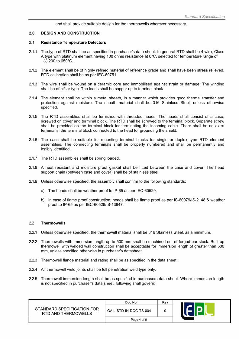
Standard Specification
STANDARD SPECIFICATION FOR RTD AND THERMOWELLS
Doc No. Rev
GAIL-STD-IN-DOC-TS-004 0
Page 4 of 6
and shall provide suitable design for the thermowells wherever necessary.
2.0 DESIGN AND CONSTRUCTION 2.1 Resistance Temperature Detectors 2.1.1 The type of RTD shall be as specified in purchaser's data sheet. In general RTD shall be 4 wire, Class
A type with platinum element having 100 ohms resistance at 0°C, selected for temperature range of (-) 200 to 650°C. 2.1.2 The element shall be of highly refined material of reference grade and shall have been stress relieved.
RTD calibration shall be as per IEC-60751. 2.1.3 The wire shall be wound on a ceramic core and immobilised against strain or damage. The winding
shall be of bifilar type. The leads shall be copper up to terminal block. 2.1.4 The element shall be within a metal sheath, in a manner which provides good thermal transfer and
protection against moisture. The sheath material shall be 316 Stainless Steel, unless otherwise specified.
2.1.5 The RTD assemblies shall be furnished with threaded heads. The heads shall consist of a case,
screwed on cover and terminal block. The RTD shall be screwed to the terminal block. Separate screw shall be provided on the terminal block for terminating the incoming cable. There shall be an extra terminal in the terminal block connected to the head for grounding the shield.
2.1.6 The case shall he suitable for mounting terminal blocks for single or duplex type RTD element
assemblies. The connecting terminals shall be properly numbered and shall be permanently and legibly identified.
2.1.7 The RTD assemblies shall be spring loaded. 2.1.8 A heat resistant and moisture proof gasket shall be fitted between the case and cover. The head
support chain (between case and cover) shall be of stainless steel. 2.1.9 Unless otherwise specified, the assembly shall confirm to the following standards:
a) The heads shall be weather proof to IP-65 as per IEC-60529. b) In case of flame proof construction, heads shall be flame proof as per IS-60079/IS-2148 & weather
proof to IP-65 as per IEC-60529/IS-13947. 2.2 Thermowells 2.2.1 Unless otherwise specified, the thermowell material shall be 316 Stainless Steel, as a minimum.
2.2.2 Thermowells with immersion length up to 500 mm shall be machined out of forged bar-stock. Built-up
thermowell with welded wall construction shall be acceptable for immersion length of greater than 500 mm, unless specified otherwise in purchaser's datasheet.
2.2.3 Thermowell flange material and rating shall be as specified in the data sheet. 2.2.4 All thermowell weld joints shall be full penetration weld type only. 2.2.5 Thermowell immersion length shall be as specified in purchasers data sheet. Where immersion length
is not specified in purchaser's data sheet, following shall govern:

Standard Specification
STANDARD SPECIFICATION FOR RTD AND THERMOWELLS
Doc No. Rev
GAIL-STD-IN-DOC-TS-004 0
Page 5 of 6
Line Size Immersion length Up to 6" 280 mm 8" and above 320 mm Equipments 400 mm The immersion length of built-up thermowells shall be as per actual requirements.
2.2.6 Tip thickness of Thermowell shall be minimum 9 MM.
2.2.7 Unless otherwise specified, the following shall govern:
a) Threaded end connections shall be NPT as per ANSI/ASME B 1.20.1 b) Flanged end connections shall be to ANSI/ASME B 16.5 c) Where ring type joint flanges shall have been specified, groove shall be suitable for octagonal
rings as per ANSI/ASME B 16.20. d) Flange face finish shall be as per clauses 6.4.5.1, 6.4.5.2 and 6.4.5.3 to ANSI/ASME B 16.5.
The face finish as specified in the datasheets, shall be as follows:
125AARH : 125 to 250AARH 63 ARH : 32 to 63 AARH
2.2.8 All the thermowells in oxygen and chlorine service shall be thoroughly degreased using reagents like trichloro-ethylene or carbon tetrachloride. 3.0 NAME PLATE
3.1 Thermowell 3.1.1 The following information shall be punched on the extension of the thermowell:
a) Tag number as per purchaser's data sheets. b) Thermowell material as per purchaser's data sheets. c) Thermowell immersion length TJ'.
3.1.2 The following information shall be punched on the thermowell flange at a visible place:
a) Nominal flange size in inches and rating in pounds. b) Flange material as per purchaser's data sheets.
4.0 INSPECTION AND TESTING 4.1 Vendor shall submit following test certificates and test reports for purchasers review.
a) Material test certificate as per clause 3.2 of EN 10204 for thermowells and flanges and as per clause 2.2 for RTDs.
b) Dimensional test report. c) For instruments with rating of 600# and above, certificate of radiography / X-ray for
welded joints. Dye penetration test certificate shall be provided for joints where Radiograph / X-ray is not possible.
d) Certificate for concentricity of bore.

Standard Specification
STANDARD SPECIFICATION FOR RTD AND THERMOWELLS
Doc No. Rev
GAIL-STD-IN-DOC-TS-004 0
Page 6 of 6
e) Hydrostatic test report as per clause 4.2 of this specification.
f) Calibration report for RTD's.
g) Certificate from any statutory authority for explosion proof and weatherproof
h) Construction of RTD's head as applicable.
4.2 Hydrostatic Test 4.2.1 Each thermowell made of bar stock or built-up type shall be subjected to hydrostatic test for a time
period of 20 minutes at the following pressures:
a) Inside of the well at 100 kg/cm2 upto 600# flange rating and at 200 kg/cm2 above 600# or up to flange rating whichever is higher
b) Outside of the well as per ANSI flange rating. During and after the hydrostatic test, the thermowell shall not show any leaks or rupture.
5.0 MATERIAL OF CONSTRUCTION ---------------------------------------------------------X-------------------------------------------------------------
SNo Item Specified Material of Construction
Thermowell SS316

GAIL INDIA LIMITED
STANDARD SPECIFICATION FOR
INSTRUMENT CABLES
GAIL-STD-IN-DOC-TS-005
0 15.01.2019 Issued As Standard RKS UNU UNU
Rev Date Purpose Prepared
By Checked
By Approved
By

Standard Specification
STANDARD SPECIFICATION FOR
INSTRUMENT CABLES
Doc No. Rev
GAIL-STD-IN-DOC-TS-005 0
Page 2 of 10
TABLE OF CONTENTS
1.0 GENERAL………………………………………………………………………………………….3
2.0 DESIGN AND CONSTRUCTION……………………………………………………………….4
3.0 NAME PLATE………………………………………………………………………………….....8
4.0 INSPECTION AND TESTING…………………………………………………………………...8

Standard Specification
STANDARD SPECIFICATION FOR
INSTRUMENT CABLES
Doc No. Rev
GAIL-STD-IN-DOC-TS-005 0
Page 3 of 10
1.0 GENERAL
1.1 Scope
1.1.1 This specification, together with the data sheets attached herewith covers the requirements for
design, materials, manufacturing, inspection, testing and shipping of signal cables.
1.1.2 Cables shall comply with latest edition of the following standards prior to the date of the purchaser's
enquiry.
ASTM D 2843 Standard Test Method for Density of Smoke from the Burning or
Decomposition of Plastics.
ASTM D 2863 Test method for measuring the minimum oxygen concentration to support
candle like combustion of plastics (oxygen index).
BS-5308 Part 1 Specification for Polyethylene insulated cables.
BS-5308 Part 2 Specification for PVC insulated cables.
IEC: 540 & 540A Test methods for insulation and sheaths of electric Cables
IEC60584-3 Extension and compensating cables - Tolerances and identification system.
IEC-60331 Testing of Fire Resistant cables.
IEC-60332 Tests on bunched wires and cables
.IEC-60092 Electrical Installations of Cables.
IEC – 60574 Test on Gases Evolved during Combustion of materials from Cables - Part 1,2.
IS-1554 PVC insulated (heavy duty) electric cables-working voltage up to and
including 1100 V.
IS-3975 Mild steel wires, formed wires and tapes for armouring of cables.
IS-5831 PVC insulation and sheath of electric cables.
IS-6380 Elastomeric insulation and sheath of electric cables
IS-6474 Polyethelene Insulation and sheath of electric cables
IS-10810 Method of test for cables.
Part 40 Method for testing uniformity of coating on zinc coated articles.
Part 41 Mass of zinc coating on steel armour
Part 58 Oxygen Index test
Part 59 Determination of halogen acid gas evolved during combustion of polymeric
material taken from cables
Part 61 Flame Retardant test
Part 62 Flame Retardance test for bunched cables
Part 63 Smoke density of electric cables under fire conditions
1.1.3 In the event of any conflict between this standard specification, data sheets, statutory
regulations, related standards, codes etc., the following order of priority shall govern:

Standard Specification
STANDARD SPECIFICATION FOR
INSTRUMENT CABLES
Doc No. Rev
GAIL-STD-IN-DOC-TS-005 0
Page 4 of 10
a) Statutory Regulations
b) Data Sheets
c) Standard Specification
d) Codes and Standards
1.3 Drawings and Data
1.3.1 Detailed drawings, data and catalogues required from the vendor are indicated by the purchaser in
the vendor data requirement sheets. The required number of reproducible, prints and soft copies
should be dispatched to the address mentioned, adhering to time limits indicated.
1.3.2 Final documentation consisting of design and constructional data submitted by the vendor after
placement of order shall include the following, as a minimum.
a) Specification sheet for each type of cable. b) Cable details giving electrical characteristics, overall diameter, diameter under armour and
diameter over armour
2.0 DESIGN AND CONSTRUCTION
2.1 Constructional requirements:
2.1.1 Cable shall be Flame Retardant Low Smoke Type.
2.1.2 Voltage Class of cables shall be 1100 V.
2.1.3 Primary insulation for PVC insulated cables, shall be 85°C polyvinyl chloride Type C as per IS
5831. Thickness of primary insulation shall be 0.5 mm as a minimum. For PE insulated cables,
primary insulation shall be of 70° C Polyethylene.
2.1.4 Inner sheath colour of signal cables shall be black. Outer sheath colour shall also be black except
for cables used in intrinsically safe systems. The outer sheath colour for all such cables used in
intrinsically safe application shall be light blue. The thickness of the sheath shall be as per IS 1554. part 1.
2.1.5 Inner and outer sheath of cable shall be Flame Retardant Low Smoke made of extruded PVC Type
ST2 (90°C) as per IS 5831 and shall meet the following requirements:
a) Minimum Oxygen index of PVC shall be 30 at 27 °C ±2°C.
b) Temperature index shall be over 250 °C.
c) Inner and Outer sheath shall meet flame retardant requirements for bunched cables as
per IS 10810 (Part 62) category AF or IEC 60332 category A.
d) A rip cord shall be provided for inner sheath.
e) Outer sheath shall be suitable for protecting the cable against rodent and termite attack.

Standard Specification
STANDARD SPECIFICATION FOR
INSTRUMENT CABLES
Doc No. Rev
GAIL-STD-IN-DOC-TS-005 0
Page 5 of 10
2.1.6 Armour over inner sheath shall be of galvanised steel wire/flat. The dimensions of armour shall be
as per IS 1554 (Part 1). Requirement and methods of tests for armour material and uniformity of
galvanisation shall be as per IS 3975 and IS 10810 (Part 40) respectively.
2.1.7 Each pair/triad shall be shielded. Shield shall be of aluminium backed by mylar / polyester tape
bonded together helically applied with metallic side down having 25% overlap on either side and
100% coverage. Minimum shield thickness shall be 0.05 mm. Drain wire shall be 0.5 mm2 multi-
strand bare tinned annealed copper conductor. The drain wire shall be in continuous contact with
aluminium side of the shield.
2.1.8 Overall shield shall be of aluminium backed up by mylar/polyester tape helically applied with the
metallic side down with either side having 25% overlap and 100% coverage. Minimum shield
thickness shall be 0.075 mm. Drain wire shall be similar to individual pair/triad drain wire and shall be
over the overall shield.
2.1.9 The cores of a pair triad shall be twisted with a minimum of 10 twists per metre of cable.
2.1.10 Sequential marking of the length of the cable in meters shall be provided on the outer sheath at
every one meter. The embossing /engraving shall be legible and indelible.
2.1.11 Tolerance in overall diameter of cable shall be within ± 2 mm over offered value.
2.1.12 The cables used in installations under the jurisdiction of Director General of Mines and Safety
(DGMS) shall meet all requirements of DGMS. The word "Mining Cable" shall be embossed on the cable outer sheath as per IS 1554 (Part 1).
2.1.13 Tinning process shall be performed over cable conductor.
2.1.14 Drum length and length tolerance
2.1.14.1 The length of the cables in each drum (drum length) shall be as specified in the purchaser
data sheets .Where no drum length is indicated in the data sheet /material requisition, the
following shall be apply:
Drum length for single pair/ single triad cable : 500 metres
Drum length for multi-pair/ multi- triad cable : 1000 metres
2.1.14.2 Actual produced drum length shall not vary by more than ± 5% from the length indicated in
purchaser's datasheet or clause 2.1.14.1 of the specification
Tolerance over the total ordered length for a type of cable shall be as follows;
a) ± 5% for total length less than 5 km.
b) ± 2% for total length more than 5 km.

Standard Specification
STANDARD SPECIFICATION FOR
INSTRUMENT CABLES
Doc No. Rev
GAIL-STD-IN-DOC-TS-005 0
Page 6 of 10
2.1.15 Specific Requirements for fire resistant cable.
a. The cables shall have circuit integrity as per IEC 60331.
b. Primary insulation shall be heat resisting elastomeric which can withstand temperature up
to 90°C such as silicon rubber/mica glass tape/EPR (medium grade) as per IS 6380.
Insulation thickness shall be 1.0mm minimum and shall confirm to IEC 60092.
c. A wrapping of tape made of PETP (polyethylene terephthalate) /woven glass shall be
provided over core insulation.
d. Individual pair triad shall be shielded. The shield shall be aluminium backed by glass
mica / PETP tape with the metallic side down helically applied with 25% overlap on either
side and 100% coverage. Minimum shield thickness shall be as per IEC 60092. Drain wire
shall be 0.5mm2 (7/0.3mm dia). Multi-stranded bare tinned annealed copper conductor.
Drain wire shall be in continuous contact with aluminium side of the shield.
e. Inner and outer sheath shall be made of low smoke, heat resistant, oil resistant and flame
retardant material with oxygen index over 30, temperature index shall be over 250°C. Acid
generation shall be maximum 20% by weight as per IEC 60754. Smoke density rating not to
exceed 60% as per ASTM D 2843.
f. The thickness of the sheath shall be as per IEC 60092. Inner and outer sheath colour shall be
orange. A rip cord shall be provided for inner sheath.
g. Armour bedding over inner sheath shall be of special high oxygen index, low smoke halogen
free fire resisting compound.
2.2 Electrical Characteristics
a. Maximum DC resistance of the conductor of the finished cable shall not exceed 12.3 Ω I km at
20°C for cables with 1.5 mm2 conductors and 39.7 Ω I km at 20°C for cables with 0.5 mm2 conductors. b. Mutual Capacitance for PVC Insulated cables. The mutual capacitance of between
pairs/triads or adjacent cores shall not exceed of 250 pF / metre at a frequency of 1 KHz.
c. Mutual Capacitance for PE Insulated cables. The mutual capacitance between the pairs/triads
shall not exceed of 100 pF / metre at a frequency of 1 KHz.
d. Capacitance between any core or screen. The capacitance between any core and screen
shall not exceed a maximum of 400 pF / meter at a frequency of 1 KHz.
e. L/R ratio of adjacent core shall not exceed 40 uH / Ω.for cables with 1.5 mm2 conductors
and 25 micro H / Ω for cables with 0.5 mm2 conductors.
f. The drain wire resistance including shield shall not exceed 30 Ω. I km.
g. Electrostatic noise rejection ratio of the finished cable shall be over 76 dB.

Standard Specification
STANDARD SPECIFICATION FOR
INSTRUMENT CABLES
Doc No. Rev
GAIL-STD-IN-DOC-TS-005 0
Page 7 of 10
2.3 Type I (Single pair / Triad shielded).
a. Each core shall be 1.5 mm2 made of 7 stranded annealed tinned electrolytic copper
conductor. Each strand shall be 0.53 mm dia.
b. Colour of core insulation shall be black and blue in pair and black, blue and brown in a triad.
c. All other specifications shall be as per clauses 2.1. and 2.2 of this specification.
2.4 Type-II (Multi-pair / Multi-triad cable with individual pair / triad shield and overall
shield)
a. Conductor sizes shall be 0.5mm2 made up of 7 strands of annealed tinned electrolytic copper
conductor. Each strand shall be of 0.3 mm diameter. Tinned conductor copper wire.
b. Overall twist of all pair / triads shall be as per vendor's standard.
c. A pair of communication wire shall be provided for multipair / multitriad cables. Each wire
shall be 0.5 mm2 of plain annealed single or multistrand copper conductor with 0.4 mm thick
85°C PVC insulation. Insulation shall be green and red colour coded.
d. A pair identification shall be with numbers at interval of not more than 250 mm.
e. All other specifications shall be as per clauses 2.1. and 2.2 of this specification.
2.5 Type-Ill (Multi-pair / Multi-triad cable with only overall shield)
The cable shall be same as type-II cable, except that the individual pair/triad shall not have
shielding.
2.6 Type-IV (Multi-pair / Multi-triad cable with individual pair shield and overall shield)
The cable shall be same as Type II, except conductor size shall be 1.5 mm2 made of 7
stranded annealed tinned electrolytic copper conductor. Each strand shall be of 0.53 mm dia.
2.7 Type-V (Multi-pair / Multi-triad cable with overall shield only) The cable shall be same as type IV except that the individual pair/triad shall not have the
shielding.
2.8 Wiring Coding The wiring shall be marked by colour code to differentiate the signal level/type according to the following table:
Function Wire Colour Outer Jacket Colour FF signals Orange (+) / Blue (-) Orange
Signals for DCS Black (+) / White (-) Grey Signals for ESD/FGS Black (+) / White (-) Red
Intrinsically safe signals Black (+) / White (-) Blue Thermocouple signals Green (+) / White (-) Green
AC power Brown (Ph) / Blue (Ne) Black DC power Red (+) / Black (-) Black
Safety earth - Green/Yellow

Standard Specification
STANDARD SPECIFICATION FOR
INSTRUMENT CABLES
Doc No. Rev
GAIL-STD-IN-DOC-TS-005 0
Page 8 of 10
Instrument earth - Black outer, Green/Yellow sheath
3.0 NAMEPLATE
3.1 Each cable drum shall be marked with the following information at a visible place;
a) Manufacturer's name
b) Type and size of the cable with cable indicated in material requisition.
c) Length of the cable in meters contained in the drum.
d) Gross weight
e) Drum number
f) Direction of rotation of drum for unwinding by means of an arrow.
g) Purchase order number.
4.0 INSPECTION AND TESTING
4.1 Unless otherwise specified purchaser reserves the right to test and inspect all the items at the
vendors work in line with the inspection test plan for signal cables..
4.2 Vendor shall furnish raw material test certificates for conductor, PVC / PE etc to prove the quality
and composition of the materials used for manufacturing the cable to the satisfaction of purchaser
or their authorised representative during various stages of expediting and inspection.
4.3 Type test, routine test and acceptance tests shall be carried out as per relevant Indian Standard
(IS), unless specified otherwise.
4.4 Type Test
4.4.1 Certificates from third party or purchaser's authorised representative for the following shall be
furnished by vendor for cables similar to those being offered ;
a) Flame retardant test on bunched cables.
b) Electrostatic noise rejection test
c) Fire resistance test
4.4.2 Vendor shall submit the following test certificates and test reports as per IS 10810 for each
batch for purchaser's review:
a) Physical tests for insulation and outer sheath as given below as minimum:
i) Tensile strength and elongation at break
ii) Ageing in air oven.
iii) Shrinkage test
iv) Hot deformation
v) Loss of mass in air oven

Standard Specification
STANDARD SPECIFICATION FOR
INSTRUMENT CABLES
Doc No. Rev
GAIL-STD-IN-DOC-TS-005 0
Page 9 of 10
vi) Heat shock test
vii) Thermal stability
b) Test for armouring wires / strips.
c) H.V. Water Immersion Tests.
4.5 Routine Tests
4.5.1 Each of the following tests shall be carried out by vendor during various stages of manufacture on
each finished cable drum.
a) Spark test as per BS 5308 Part 2.
b) Conductor resistance
c) High voltage test as per BS 5308 Part 2
d) Armour resistance test (for mining cables).
e) Mutual capacitance and capacitance between any core or screen.
f) Inductance and L/R ratio. d) Annealing test (for copper)
4.6 Acceptance Tests
4.6.1 Following acceptance tests shall be carried out by vendor on representative samples taken from
manufactured lot:
a) Finished cable dimensions
b) Conductor resistance
c) Thickness of insulation and sheath.
d) Tensile strength and elongation at break of insulation and sheath.
e) Pair twisting, laying and identification.
f) Shield overlap, drain wire resistance and continuity check.
g) Armour resistance test (for mining cables).
h) Uniformity of zinc coating on armour.
i) Insulation resistance (volume resistivity) as per BS 5308 Part 2.
j) High voltage.
k) Test for rodent and termite repulsion.
l) Mutual capacitance and capacitance between any core or screen
m) Inductance and L/R ratio
n) Oxygen and Temperature index as per ASTM D 2863.
o) Flame retardant Test on sample cable as per IS 10810 Part 61.
p) Acid Generation test IEC 60754 / IS 10810 Part 59 (for fire resistant cables)
q) Smoke density test ASTM D 2843 / IS 10810 Part 63 (for fire resistant cables)
Standard Specification
STANDARD SPECIFICATION FOR
INSTRUMENT CABLES
Doc No. Rev
GAIL-STD-IN-DOC-TS-005 0
Page 10 of 10
r) Overall finish and drum length check.
s) Swedish Chimney test
4.7 Witness Inspection
4.7.1 Vendor shall offer all cables for pre-dispatch inspection to purchaser or their authorized
representative and following test/checks shall be carried out as minimum:
a) Acceptance tests as per clause 4.6 on representative samples.
b) Review of all certificates and test reports as indicated in clause 4.0.
4.8 Immediately after completion of electrical tests, the ends of the cable shall be sealed to prevent
ingress of moisture with suitable PVC / rubber caps.
4.9 In the event no witness inspection is carried out by purchaser, the tests shall anyway be
completed by the vendor and documents for the same shall be submitted to purchaser for scrutiny.
----------------------------------------------------------------X-----------------------------------------------------------------

GAIL INDIA LIMITED
STANDARD SPECIFICATION FOR
JUNCTION BOXES & CABLE GLANDS
GAIL-STD-IN-DOC-TS-006
0 15.01.2019 Issued As Standard RKS UNU UNU
Rev Date Purpose Prepared
By Checked
By Approved
By

Standard Specification
STANDARDL SPECIFICATION FOR
JUNCTION BOXES & CABLE GLANDS
Doc No. Rev
GAIL-STD-IN-DOC-TS-006 0
Page 2 of 7
TABLE OF CONTENTS
1.0 GENERAL……………………………………………………………………………………….3
2.0 DESIGNS AND CONSTRUCTION…………………………………………………………….4
3.0 NAME PLATE…………………………………………………………………………………...6
4.0 INSPECTION AND TESTING………………………………………………………………….6

Standard Specification
STANDARDL SPECIFICATION FOR
JUNCTION BOXES & CABLE GLANDS
Doc No. Rev
GAIL-STD-IN-DOC-TS-006 0
Page 3 of 7
1.0 GENERAL
1.1 Scope
1.1.1 This standard specification, together with the data sheets attached herewith, covers the
requirements for design, materials, nameplate marking, testing and shipping of junction boxes
and cable glands which include the following types:
a) Electrical junction boxes
b) Pneumatic junction boxes
c) Cable glands (whenever specified)
1.1.2 The related standards referred to herein and mentioned below shall be of the latest editions prior
to the purchaser's enquiry;
ANSI/ASME American National Standards Institute / American Society of Mechanical
Engineers.
B 1.20.1 Pipe Threads, General Purpose (Inch).
EN 10204 Inspection Documents For Metallic Products.
IEC-60079 Electrical Apparatus for Explosive Gas Atmosphere.
IEC-60529 Degrees of Protection Provided by Enclosures. (IP Code)
IS-5 Colours for ready mixed paints and enamels.
IS-13947 Specification for Low Voltage Switchgear and Control gear.
IS-2148 Electrical Apparatus for Explosive Gas Atmospheres - Flame proof Enclosures
'd'.
1.1.3 In the event of any conflict between this specification, data sheets, related standards, codes etc.,
the following order of priority shall govern:
a) Statutory Regulations
b) Data Sheets
c) Standard Specification
d) Codes and Standards
1.2 Drawings and Data
1.2.1 Detailed drawings, data, catalogues and manuals required from the vendor are indicated by the
purchaser in vendor data requirement sheets. The required number of reproducible, prints and soft
copies, shall be sent to the address mentioned, adhering to the time limits indicated.
1.2.2 Final documentation consisting of design data and installation manual submitted by the vendor after
placement of purchase order shall include the following, as a minimum;
a) Specification sheet for each junction box and its accessories like cable glands etc.

Standard Specification
STANDARDL SPECIFICATION FOR
JUNCTION BOXES & CABLE GLANDS
Doc No. Rev
GAIL-STD-IN-DOC-TS-006 0
Page 4 of 7
b) Certified drawing sheets for each junction box and its accessories, which shall provide
dimensional details, internal constructional details (general arrangement details), and material
of construction.
c) Copy of type test certificates.
d) Copy of test certificates for all the tests indicated in clause 4.0 of this specification. e) Installation procedure for junction boxes and its accessories.
2.0 DESIGN AND CONSTRUCTION
2.1 Junction Boxes
2.1.1 Junction boxes shall be either of the following type as specified in data sheets.
a) Weather proof j unction boxes.
b) Weather proof and flameproof junction boxes.
No other type of junction boxes shall be offered / supplied unless specifically indicated otherwise.
2.1.2 Unless otherwise specified, the enclosure shall conform to the following standards:
Weatherproof housing : IP 65 to IEC-60529
Flameproof housing : Flameproof/Ex (d) as per IEC-60O79.
2.1.3 Number of entries and their location shall be as per data sheets. Junction boxes with top entries
shall not be offered. The size of cable entries shall be as per the cable sizes indicated in the data
sheet.
2.1.4 Multi-pair junction boxes shall be provided with telephone sockets and plugs for connection of hand-
powered telephone set.
2.1.5 Electrical Junction Boxes
a) The material of construction of electrical junction boxes shall be die-cast aluminium of minimum 5
mm thick (LM-6 alloy).
b) Weather proof junction box shall have hinged type door with neoprene gasket, which shall be
fixed to the box by plated countersunk screws.
c) Flameproof junction box shall have detachable cover, which shall be fixed to the box by means
of cadmium plated triangular head/hexagonal head screws.
d) Flameproof junction boxes for signal, alarm and control shall have the following warning
engraved/integrally cast on the cover;
"Isolate power supply elsewhere before opening"
e) Power junction boxes (junction boxes for power supply cable / distribution) shall have
either the warning cast or shall have warning plate with following marking;
"Isolate power supply elsewhere before opening".
Unless otherwise indicated in the job specification, power junction boxes shall be suitable for
incoming armoured power cable up to 150 sq.mm conductor size.

Standard Specification
STANDARDL SPECIFICATION FOR
JUNCTION BOXES & CABLE GLANDS
Doc No. Rev
GAIL-STD-IN-DOC-TS-006 0
Page 5 of 7
f) Terminals shall be spring loaded, vibration proof, clip-on type, mounted on nickel plated steel
rails complete with end cover and clamps for each row.
g) All terminals used in signal, alarm and control junction boxes shall be suitable for accepting
minimum 2.5sq.mm copper conductor, in general.
h) Terminal used in power junction boxes / power supply distribution box shall be suitable for
accepting conductor size of 4 Sq. mm to upto 120 sq. mm. Exact requirement shall be
specified in data sheet/job specification. Higher size of terminals provided when indicated. Bus
bar terminals shall be provided for conductor size 50 sq.mm and above. Suitable size of lugs
shall be provided to suit conductor size specified.
i) Each junction shall have minimum of 30% spare terminal of those actually required to be utilised.
Unless higher number of terminal are specified in the purchaser's data sheet, the number of terminals for various types of junction boxes shall be as follows;
24 Nos. for 6 pair junction box.
48 Nos. for 12 pair junction box
36 Nos. for 6 triad junction box.
48 Nos. for 8 triad junction box.
j) Terminals shall be identified as per the type of input signal indicated in data sheets e.g all terminal
for intrinsically safe inputs shall be blue while others shall be grey in colour.
k) Junction boxes shall be provided with external earthing lugs.
l) Sizing shall be done with due consideration for accessibility and maintenance in accordance with
the following guidelines;
i) 50 to 60 mm gap between terminals and sides of box parallel to terminal strip for upto 50
terminals and additional 25 mm for each additional 25 terminals.
j) 100 to 120 mm between two terminal strips for upto 50 terminals and additional 25 mm for each
additional 25 terminals.
iii) Bottom/top of terminal shall not be less than 100 mm from bottom / top of the junction box.
2.1.6 Pneumatic Junction Boxes
a) Pneumatic junction boxes shall be made of 3 mm thick hot rolled steel. They shall have
necessary neoprene gasket between door and body. Door shall be flush with the box and
shall be hinged type and provided with wing nuts.
b) Single tube entries shall be suitable for 6 mm O.D copper tube with bulk head fittings. Multi
tube bundle entry shall be suitable for the data furnished in data sheets.
2.1.7 Painting
a) Surface shall be prepared for painting. It shall be smooth and devoid of rust and scale.

Standard Specification
STANDARDL SPECIFICATION FOR
JUNCTION BOXES & CABLE GLANDS
Doc No. Rev
GAIL-STD-IN-DOC-TS-006 0
Page 6 of 7
b) Two coats of lead-free base primer and two final coats of lead free epoxy based paint shall
be applied both for interior and exterior surfaces.
c) The colour shall be as specified in data sheets. However, following philosophy shall be
followed, in general:
(i) Light blue for all intrinsically safe junction boxes.
(ii) Light grey for all others
2.2 Cable glands, Plugs and Reducers/Adaptors
2.2.1 Cable glands shall be supplied by vendor whenever specified. 2.2.2 Cable glands shall be double compression type for use with armoured cables.
2.2.3 The cable glands shall be of nickel plated brass, as a minimum and shall be provided with PVC
shrouds.
2.2.4 The cable glands shall be weatherproof. Whenever specified they shall also be flameproof and
certificate for the specified electrical area classification specified in the data sheets.
2.2.5 Cable glands shall be supplied to suit the cable dimensions indicated along with tolerances in data
sheets. Various components like rubber ring, metallic ring, metallic cone and the outer / inner nuts
etc. shall be capable of adjusting to the indicated tolerances of cable dimensions.
2.2.6 Reducers / adapters shall be supplied as per details indicated in data sheets. They shall be nickel-
plated brass, as a minimum. These shall also be weatherproof and / or flame proof wherever
specified and certified for the electrical area classification specified in the data sheets.
2.2.7 Plugs shall be provided wherever specified. They shall be of nickel-plated brass.
2.2.8 Plugs shall be certified flameproof when used with flameproof junction boxes.
3.0 NAME PLATE
Each junction box shall have an anodised aluminium nameplate permanently fixed to it at a visible
place furnishing the following information;
a) Tag number as per purchaser's data sheet.
b) Manufacturer's serial number and model number.
c) Manufacturer's name/trade mark.
d) Stamp of certifying agency with certificate number.
e) Electrical area classification.
4.0 INSPECTION AND TESTING
4.1 Unless otherwise specified, purchaser reserves the right to test and inspect all the items at the
vendor's works in line with inspection test plan for junction boxes and cable glands.

Standard Specification
STANDARDL SPECIFICATION FOR
JUNCTION BOXES & CABLE GLANDS
Doc No. Rev
GAIL-STD-IN-DOC-TS-006 0
Page 7 of 7
4.2 Vendor shall submit following test certificates and test reports for purchaser's review:
a) Material test certificates as per clause 2.2 of EN 10204
b) Pressure test on castings for flameproof junction boxes.
c) Dimensional test report.
d) High voltage and insulation resistance test report.
e) Air leak test report on pneumatic junction boxes.
f) Certificate from statutory body for suitability to install in specified hazardous area.
4.3 Witness Inspection
4.3.1 All junction boxes, cable glands and other accessories shall be offered for pre-dispatch inspection for
the following, as a minimum;
a) Physical dimensional verification and workmanship on representative samples.
b) High voltage and Insulation resistance test on representative samples.
c) Air leak test report on representative samples of pneumatic junction boxes.
d) Review of all certificates and test reports as indicated in clause 4.2 of this specification.
4.3.2 In the event when witness inspection is not carried out by purchaser, the tests shall anyway be
completed by the vendor and documents for the same shall be submitted for scrutiny of purchaser. ----------------------------------------------------------------X----------------------------------------------------------------------

GAIL INDIA LIMITED
STANDARD SPECIFICATION FOR
INSTRUMENT TUBE FITTINGS (STAINLESS STEEL TUBE FITTINGS)
GAIL-STD-IN-DOC-TS-007
0 15.01.2019 Issued As Standard RKS UNU UNU
Rev Date Purpose Prepared
By Checked
By Approved
By

Standard Specification
STANDARD SPECIFICATION FOR
INSTRUMENT TUBE FITTINGS (STAINLESS STEEL TUBE FITTINGS)
Doc No. Rev
GAIL-STD-IN-DOC-TS-007 0
Page 2 of 6
CONTENTS
1.0 GENERAL----------------------------------------------------------------------------------------------------------3 2.0 DESIGN AND CONSTRUCTION------------------------------------------------------------------------------3 3.0 NAME PLATE---------------------------------------------------------------------------------------------------4 4.0 INSPECTION AND TESTING------------------------------------------------------------------------------4 ANNEXURES: ANNEXURE - 1: HYDROSTATIC TEST PRESSURES FOR INSTRUMENT TUBE FITTINGS

Standard Specification
STANDARD SPECIFICATION FOR
INSTRUMENT TUBE FITTINGS (STAINLESS STEEL TUBE FITTINGS)
Doc No. Rev
GAIL-STD-IN-DOC-TS-007 0
Page 3 of 6
1.0 GENERAL
1.1 Scope
1.1.1 This standard specification, together with the data sheets attached herewith, covers the
requirements for the design, materials, inspection, testing of instrument tube
fittings which includes the following types:
a) Stainless steel compression fittings (for stainless steel tube)
b) Brass compression fittings (for copper tube)
1.1.2 The related standards referred to herein and mentioned below shall be of the latest editions
prior to the date of the purchaser's enquiry: -
ANSI/ASME American National Standards Institute/American Society of Mechanical
Engineers
B 1.20.1 Pipe Threads General Purpose (Inch).
B 16.11 Forged Steel Fittings - Socket Welding and Threaded.
BS-4368 Metallic tube connectors for fluid power and general use. Specification
for type test requirements
ASTM F 1387 Standard Specification for Performance of Piping and Tubing
Mechanically Attached Fittings
EN 10204 Inspection Documents For Metallic Products.
IS-319 Specification for free cutting Brass Bars, Rods and Sections.
ISA International Society of Automation
RP 42.1 Nomenclature for Instrument Tube Fittings.
1.1.3 In the event of any conflict between this standard specification, data sheets, statutory
regulations, related standards, codes etc., the following order of priority shall govern:
a) Statutory Regulations
b) Data Sheets
c) Standard Specification
d) Codes and Standards
2.0 DESIGN AND CONSTRUCTION
2.1 Stainless Steel Tube Fittings
2.1.1 Nomenclature of all tube fittings shall be as per ISA RP 42.1.
2.1.2 Fittings shall be of flare less compression type having four-piece (for double compression type)
construction consisting of two ferrules, nut and body or three piece (compression type) construction
consisting of single ferrule, nut and body suitable for use on tubes of specified material for example
stainless steel tubes conforming to ASTM A269 TP 316L with hardness in the range of HRB 70 to
79.

Standard Specification
STANDARD SPECIFICATION FOR
INSTRUMENT TUBE FITTINGS (STAINLESS STEEL TUBE FITTINGS)
Doc No. Rev
GAIL-STD-IN-DOC-TS-007 0
Page 4 of 6
2.1.3 All parts of the tube fittings shall be of 316 Stainless Steel unless specified otherwise.
2.1.4 Hardness of the ferrules shall be in the range of HRB 85-90 so as to ensure a hardness difference
of the order of 5 to 10 between tube and fittings for better sealing.
2.1.5 Nuts and ferrules of a particular size shall be interchangeable for each type.
2.1.6 Spanner hold shall be metric.
2.1.7 Threaded ends of fittings shall be NPT as per ANSI B 1.20.1.
2.1.8 Specific techniques like silver plating shall be used over threading in order to avoid jamming and
galling.
2.1.9 Ferrule finish and fitting finish shall be such that there is no abrasion/galling when the nut is
tightened.
2.1.10 All instrument tube fittings in oxygen and chlorine service shall be thoroughly degreased using
reagents like trichloro-ethylene or carbon tetrachloride. End connection shall be plugged after
degreasing process in order to avoid entrance of grease or oil particles.
2.2 Copper Tube Fittings
2.2.1 Nomenclature of all tube fittings shall be as per ISA RP 42.1.
2.2.2 Fittings shall be of flare less compression type and of three-piece construction consisting of ferrule,
nut
2.2.3 and body suitable for use on copper tubes conforming to ASTM B68 /B68M, hardness not exceeding
HRB 50.
2.2.4 All parts shall be manufactured from brass as per IS 319 bar stock and nickel plated.
2.2.5 For better grip, vendor shall maintain hardness difference between tube and ferrule and indicate the
same along with the offer.
Threaded ends of fittings shall be NPT as per ASME B 1.20.1
Spanner hold shall be metric.
3.0 NAMEPLATE
3.1 No separate nameplates are required on the fittings. However, manufacturer's name/trademark
should be punched on a visible place on the body of each fitting for easy identification.
4.0 INSPECTION AND TESTING
4.1 Unless otherwise specified, purchaser reserves the right to test and inspect all items at vendor's
works, inline with the inspection test plan for instrument tube fittings.
4.2 Vendor shall submit following test certificates and test reports for purchaser's review:
4.2.1 Type test reports for following tests in accordance with BS-4368 Part IV:
a) Hydrostatic proof pressure test.

Standard Specification
STANDARD SPECIFICATION FOR
INSTRUMENT TUBE FITTINGS (STAINLESS STEEL TUBE FITTINGS)
Doc No. Rev
GAIL-STD-IN-DOC-TS-007 0
Page 5 of 6
b) Minimum hydrostatic burst pressure test.
c) Disassembly and reassembly test.
d) Minimum static gas pressure (vacuum) test.
e) Maximum static gas pressure test.
f) Hydraulic impulse and vibration test.
4.2.2 Material test certificates as per clause 3.1 B of EN 10204.
4.2.3 Routine test reports for following tests:
a) Hydrostatic Test
Instrument tube fittings shall be hydrostatically tested at ambient temperature at test
pressures given in Annexure 1 of this specification. During and after the hydrostatic test,
the tube fittings shall not show any leakage or rupture.
b) Pneumatic pressure test
The fittings shall be tested at 7 kg/cm2g of dry air. There shall not be any visible leakage
when immersed in water or coated with a leak detection solution.
c) Disassembly and reassembly test.
d) Hardness verification:
Hardness test shall be carried out on each rod used for machining ferrules. Vendor shall
ensure that after machining, the finished ferrules shall meet the required hardness given
in the specification.
e) Dimensional test report
4.3 Witness Inspection
4.3.1 All fittings shall be offered for pre-dispatch inspection for the following as a minimum:
a) Physical dimensional verification and workmanship on representative samples.
b) Hydrostatic and pneumatic tests as per clause 4.2.3 of this specification on representative
samples.
c) Hardness verification as per clause 4.2.3 of this specification.
d) Diassembly and reassembly test on representative samples.
e) Review of all certificates and test reports as indicated in clause 4.2 of this specification.
4.3.2 In the event when no witness inspection is carried out by purchaser, vendor shall anyway complete
the tests and test reports for the same shall be submitted to purchaser for scrutiny.

Standard Specification
STANDARD SPECIFICATION FOR
INSTRUMENT TUBE FITTINGS (STAINLESS STEEL TUBE FITTINGS)
Doc No. Rev
GAIL-STD-IN-DOC-TS-007 0
Page 6 of 6
ANNEXURE – 1
HYDROSTATIC TEST PRESSURES FOR INSTRUMENT TUBE FITTINGS
Sr. No.
Size of Tube Fittings
Material Line Pressure Class
Max Working Pressure
Hydrostatic Test Pressure
1 6mm and 1/2" Stainless Steel < or = 600# 102 Kg/cmzg 153 Kg/cmzg
2 6mm and 1/2" Stainless Steel > or = 900# to
< or = 1500#
253 Kg/cm'g 383 Kg/cm'g
3 ¼ “ and 3/8" Brass > or = 900# to
< or = 1500#
53 Kg/cmzg 80 Kg/cmzg

GAIL INDIA LIMITED
STANDARD SPECIFICATION FOR
INSTRUMENT TUBING (STAINLESS STEEL TUBES)
GAIL-STD-IN-DOC-TS-008
0 15.01.2019 Issued As Standard RKS UNU UNU
Rev Date Purpose Prepared
By Checked
By Approved
By

Standard Specification
STANDARD SPECIFICATION FOR
INSTRUMENT TUBE (STAINLESS STEEL TUBES)
Doc No. Rev
GAIL-STD-IN-DOC-TS-008 0
Page 2 of 7
TABLE OF CONTENTS
1.0 GENERAL--------------------------------------------------------------------------------------------------3
2.0 DESIGN AND CONSTRUCTION---------------------------------------------------------------------4
3.0 NAME PLATE----------------------------------------------------------------------------------------------5
4.0 INSPECTION AND TESTING--------------------------------------------------------------------------5
ANNEXURE:
ANNEXURE - 1: MAXIMUM WORKING PRESSURE AND HYDROSTATIC TEST
PRESSURES FOR INSTRUMENT TUBING

Standard Specification
STANDARD SPECIFICATION FOR
INSTRUMENT TUBE (STAINLESS STEEL TUBES)
Doc No. Rev
GAIL-STD-IN-DOC-TS-008 0
Page 3 of 7
1.0 GENERAL
1.1 Scope
1.1.1 This standard specification, together with the data sheets attached herewith, covers the
requirements for the design, materials, inspection, testing and shipping of Instrument Tubing
which includes the following types: -
a) Stainless steel tubes
b) Copper tubes
1.1.2 The related standards referred to herein and mentioned below shall be of the latest edition
prior to the date of purchaser's enquiry;
ASTM American Society for Testing and Materials.
A269 /A269- 15A Standard Specification for Seamless and Welded Austenitic
Stainless Steel Tubing for General Services.
A632 Standard Specification for Seamless and Welded Austenitic Stainless Steel Tubing (Small Diameter) for General Services.
B 251 Specification for general requirements for wrought seamless
copper and copper alloy tube.
B 251M Specification for general requirements for wrought seamless
copper and copper alloy tube (Metric)
B 68/B68M Specification for seamless copper tube, bright annealed.
E 243 Standard Practice for Electromagnetic (Eddy - Current)
Examination of Copper and Copper - Alloy Tubes
EN 10204 Inspection Documents for Metallic Products
1.1.3 In the event of any conflict between this standard specification, job specification/data sheets,
statutory regulations, related standards, codes etc. the following order of priority shall govern:
a) Statutory regulations
b) Job specification
c) Standard specification
d) Codes and standards
1.2 Drawings and Data
1.2.1 Detailed drawings, data, catalogues and manuals required from the vendor are indicated by the
purchaser in vendor data requirement sheets. The required number of reproducible, prints and soft
copies shall be dispatched to the address mentioned adhering to the time limits indicated.

Standard Specification
STANDARD SPECIFICATION FOR
INSTRUMENT TUBE (STAINLESS STEEL TUBES)
Doc No. Rev
GAIL-STD-IN-DOC-TS-008 0
Page 4 of 7
1.2.2 Final documentation consisting of design data by the contractor after placement of purchase order
shall include the following as a minimum;
a) Specification sheet for each type of tube.
b) Copy of test certificates of all tests indicated in clause 4.0 of this specification.
2.0 DESIGN AND CONSTRUCTION
2.1 Stainless Steel Tubes
2.1.1 The tubes shall be 316L Stainless Steel fully annealed, seamless and cold drawn as per ASTM A
269/A269-15A.
2.1.2 The hardness of the tubes shall be limited to HRB 70-79. Equivalent hardness as Rockwell
superficial scale (30T/15T) or Vicker's hardness scale shall also be acceptable.
2.1.3 Tubes shall have good surface finish and shall be free from scratches burrs etc. and suitable for
bending.
2.1.4 Maximum working pressure shall be as per Annexure - 1 attached with this specification.
2.1.5 Tubes shall preferably be supplied in length of 5 to 6 metres without welding in between. Tube
length less than 5 meters shall be rejected.
2.1.6 All tubes in oxygen and chlorine service shall be thoroughly degreased using reagents like trichloro-
ethylene or carbon tetrachloride and tube ends shall be plugged after degreasing process in order
to avoid entrance of grease or oil particles.
2.2 Copper Tubes
2.2.1 Copper Tubes (PVC Jacketed)
a) The tube shall be soft annealed copper with 6mm OD and a wall thickness of 1.0mm as per
ASTM B 68/B68 M copper No. C 12200. b) The tube shall be jacketed with black PVC. The jacket thickness shall be 1.6mm. The PVC
jacket shall confirm to ASTM D-1047. c) The tube ends shall be plugged prior to transportation. d) The tube shall be continuous length without any brazing in between. e) The length of single tube shall preferably be 100 metres. However any tube length less than 70
meters shall be rejected unless specifically required otherwise in job specification. f) The dimensional tolerances shall be as per ASTM B 251/B251 M.
2.2.2 Bare Copper Tubes (For Steam Tracing)
a) The tube shall be soft annealed copper with 3/8" (10mm) OD with wall thickness of 0.049" or 6mm OD with wall thickness of 1.0mm as per ASTM B68/B68 M,copper No. C12200.

Standard Specification
STANDARD SPECIFICATION FOR
INSTRUMENT TUBE (STAINLESS STEEL TUBES)
Doc No. Rev
GAIL-STD-IN-DOC-TS-008 0
Page 5 of 7
b) The tube ends shall be plugged prior to transportation.
c) The tube shall be continuous length without any brazing in between.
d) The length of single tube shall preferably be 100 metres. However any tube length less
than 70 meters shall be rejected unless specifically required otherwise in job specification.
e) The dimensional tolerances shall be as per ASTM B 251/B 251M.
f) Maximum working pressure shall be 53.0kg/cm2g at 38°C unless specified otherwise.
3.0 NAME PLATE
The following information shall be marked on the stainless steel tubes:
a) Name of manufacturer
b) Type and material grade of tube
c) Tube outer diameter and wall thickness.
4.0 INSPECTION AND TESTING
4.1 Unless otherwise specified, purchaser reserves the right to test and inspect all the items at vendor's
works, inline with the inspection test plan for instrument tubing.
4.2 Vendor shall submit following test certificates and test reports for purchasers review:
a) Material test certificates as per clause 3. IB of EN 10204.
b) Hydrostatic test for stainless steel tube and bare copper tubes as per clause 4.3 of this
specification.
c) Pneumatic test for PVC jacketed copper tubes as per clause 4.4 of this specification.
d) Hardness / tension test for stainless steel tubes as per clause 4.5 of this specification.
e) Ball test for copper tubes as per clause 4.6 of this specification.
f) Eddy current examination of copper tubes as per ASTM E-243 g) Dimensional test report.
4.3 Hydrostatic test
4.3.1 Stainless steel and bare copper tube shall be hydrostatically tested at ambient temperature at test
pressures given in Annexure - 1 attached with this specification. During and after the hydraulic test,
the tubes shall not show any leaks or rupture.
4.4 Pneumatic test
4.4.1 PVC jacketed copper tubes shall be tested at 7.0 kg/cm2g of dry air. During and after
the test, tubes shall not show any leak or rupture.

Standard Specification
STANDARD SPECIFICATION FOR
INSTRUMENT TUBE (STAINLESS STEEL TUBES)
Doc No. Rev
GAIL-STD-IN-DOC-TS-008 0
Page 6 of 7
4.5 Hardness/Tension Test
4.5.1 All mother tubes shall be hardness tested for each heat prior to drawing for proper
quality control. The hardness of the drawn tubes shall be checked by Rockwell
Hardness Test. Following shall apply;
a) For tubing less than 0.65in (1.65mm) in wall thickness, Rockwell superficial
hardness test on 30T / 15T scale or Vicker's scale shall be equivalent to HRB
70 - 79.
b) Hardness test is not required for tubes smaller than l/4in (6.4mm) inside
diameter or tubes having a wall thickness thinner than 0.020in (0.51mm).
These tubes shall be tension tested in accordance with ASTM A632.
4.6 Ball Test
4.6.1 Ball test shall be carried on all copper tubes to ensure clear opening of the tube. The
OD of the ball shall be minimum 1.0mm for 6.0mm OD tube and 2.0mm for 3/8" (10mm)
OD tube.
4.7 Witness Inspection
4.7.1 All tubes shall be offered for pre-dispatch inspection for the following, as a minimum;
a) Physical dimensional verification and workmanship.
b) Hardness / tension test for stainless steel tubes.
c) Hydrostatic and pneumatic tests on representative samples.
d) Ball test on copper tubes on representative samples.
e) Eddy current examination of copper tubes on representative samples.
f) Review of all certificates and test reports as indicated in clause 4.2 of this
specification.
4.7.2 In the event that the witness inspection is not carried out by purchaser, contractor shall
anyway complete the tests and test reports for the same shall be submitted to
purchaser for scrutiny.

Standard Specification
STANDARD SPECIFICATION FOR
INSTRUMENT TUBE (STAINLESS STEEL TUBES)
Doc No. Rev
GAIL-STD-IN-DOC-TS-008 0
Page 7 of 7
ANNEXURE - 1
MAXIMUM WORKING PRESSURE AND
HYDROSTATIC TEST PRESSURES FOR INSTRUMENT TUBING
Sr. No.
Size of Tube (OD)
Material Line Pressure Class
Thickness Maximum Working Pressure
Hydrostatic Test Pressure
1 1/2" (12mm)
Stainless Steel
< or = 600# 0.049" (1.2mm) 102 Kg/ cmzg 153 Kg/ cmzg
2
V2" (12mm)
Stainless Steel
> or = 900# to < or =1500#
0.065" (1.65mm) 253 Kg/ cmzg 383 Kg/ cmzg
3
(6mm) Stainless Steel
< or = 600# 1.00mm 102Kg/cmzg 153 Kg/cmzg
4 ¼” (6mm) Stainless Steel
> or = 900# to < or =1500#
0.065" (1.65mm) 253 Kg/ cmzg 383 Kg/cmzg
5 3/8" (10mm)
Copper < or = 300# 0.049" 53 Kg/ cmzg 80 Kg/ cmzg
6 ¼” (6mm) Copper < or = 300# 1.00mm 53 Kg/ cmzg 80 Kg/ cmzg
GAIL INDIA LIMITED
STANDARD SPECIFICATION FOR
INSTRUMENT VALVE AND MANIFOLDS
GAIL-STD-IN-DOC-TS-009
0 15.01.2019 Issued As Standard RKS UNU UNU
Rev Date Purpose Prepared
By Checked
By Approved
By

Standard Specification
STANDARD SPECIFICATION FOR
INSTRUMENT VALVE & MANIFOLDS
Doc No. Rev
GAIL-STD-IN-DOC-TS-009 0
Page 2 of 8
TABLE OF CONTENTS
1.0 GENERAL--------------------------------------------------------------------------------------3
2.0 DESIGN AND CONSTRUCTION-------------------------------------------------------4
3.0 NAME PLATE-------------------------------------------------------------------------------6
4.0 INSPECTION AND TESTING-----------------------------------------------------------7
ANNEXURE - 1: HYDROSTATIC TEST PRESSURES FOR INSTRUMENT VALVES AND MANIFOLDS.

Standard Specification
STANDARD SPECIFICATION FOR
INSTRUMENT VALVE & MANIFOLDS
Doc No. Rev
GAIL-STD-IN-DOC-TS-009 0
Page 3 of 8
1.0 GENERAL
1.1 Scope
1.1.1 This standard specifications, together with the data sheets attached herewith, covers the
requirements for the design, materials, inspection, testing and shipping of instrument valves
and manifolds which includes the following types:
a) Miniature instrument valves
b) Instrument valve manifolds
c) Instrument air valves
1.1.2 The related standards referred to herein and mentioned below shall be of the latest edition
prior to the date of purchaser's enquiry;
ASME/ANSI American Society of Mechanical Engineers/ American National Standards Institute
B 1.20.1 Pipe threads General Purpose (Inch)
B 16.11 Forged steel fittings-socket welding and threaded.
B 16.9 Factory made Wrought Steel Butt welding fittings.
B 16.34 Valves-Flanged. Threaded and welding end.
API-598 Valve Inspection and Testing
EN 10204 Inspection Documents for Metallic Products.
MSS Manufacturers Standardization Society of the Valve and Fittings
Industry.
SP99 Instrument Valves
1.1.3. In the event of any conflict between this standard specification, job specification/data sheets,
statutory regulations, related standards, codes etc. the following order of priority shall govern:
a) Statutory Regulations
b) Data Sheets
c) Standard Specification
d) Codes and Standards
1.3 Drawings and Data
1.3.1 Detailed drawings, data, catalogue and manuals etc. required from the vendor is indicated by the
purchaser in vendor data requirement sheets attached with material requisition. The required
number of reproducible, prints and soft copies shall be dispatched to the address mentioned in the
material requisition, adhering to the time limits indicated.
1.3.2 Final documentation consisting of design data, installation and maintenance manual etc. submitted
by the vendor after the placement of purchase order shall include the following, as a minimum:

Standard Specification
STANDARD SPECIFICATION FOR
INSTRUMENT VALVE & MANIFOLDS
Doc No. Rev
GAIL-STD-IN-DOC-TS-009 0
Page 4 of 8
a) Specification sheet for type of instrument valve and manifold.
b) Certified dimensional details showing internal constructional details and material of
construction.
c) Copy of type test certificates.
d) Copy of test certificates for all the tests indicated in clause 4.0 of this specification.
e) Installation and maintenance procedures.
2.0 DESIGN AND CONSTRUCTION
2.1 The instrument valves shall be of manufacturer proprietary design. However, the minimum
requirements specified herein must be complied.
2.2 Qualification tests (hydrostatic proof and burst tests) as per MSS SP-99 shall be conducted by
vendor for each design and size of valve to establish the cold working pressure (CW.P) rating.
2.3 For all valves and manifolds with body material of carbon steel/stainless steel, the valve trim
material shall be 316 Stainless Steel, as a minimum. Whenever body material is other than that
specified above, trim material should be same as body material as a minimum.
2.4 Unless otherwise specified, the valve packing material for all valves and manifolds shall be PTFE
only. The o-ring materials wherever used shall also be of PTFE.
2.5 The finishing and tolerances of parts like stem, piston, stem threading etc. of the offered valves and
manifolds shall be properly machined to avoid problems like galling.
2.6 The hand wheel material for all valves and manifolds shall be zinc/nickel plated carbon steel. Any
other material, if provided as per standard vendor design, shall also be acceptable.
2.7 Instrument Valves (Miniature)
2.7.1 The instrument valves shall be of globe pattern needle valves forged/ bar stock with inside screwed
bonnet, with back-seated blow out proof system.
2.7.2 Body material shall be 316 Stainless Steel unless otherwise specified.
2.7.3 The minimum cold working pressure (CWP) rating of the valve shall be as per Annexure 1 of this
specification, unless otherwise specified.
2.7.4 The end connection shall be 1/2"NPTF to ANSI B 1.20.1, unless otherwise specified.
2.7.5 Flow direction shall be marked on the body.
2.7.6 The valve dimensions shall be as follows:
a) End to end dimensions 76mm (approximately). b) Height in fully open condition - 135mm maximum. These dimensions are indicative only.

Standard Specification
STANDARD SPECIFICATION FOR
INSTRUMENT VALVE & MANIFOLDS
Doc No. Rev
GAIL-STD-IN-DOC-TS-009 0
Page 5 of 8
2.8 Valve Manifolds
2.8.1 3-Valve and 5-Valve manifolds:
2.8.1.1 3-Valve manifold
a) 3-Valve manifold shall be designed for direct coupling to differential pressure transmitters
having 2 bolt flanges with 54mm (2-1/8") centre-to-centre connections and 41.3mm (1 -
5/8") bolt-to-bolt distance.
b) 3-Valve manifold shall contain two main line block valves and an equalising bypass valve.
The valves shall be needle type. They shall use self-aligning 316 Stainless Steel ball
seats, unless otherwise specified.
2.8.1.2 5-Valve manifold
a) 5-Valve manifold shall be designed for direct coupling to differential pressure transmitters
having 2 bolt flanges with 54mm (2-1/8") centre-to-centre connections and 41.3mm (1-
5/8") bolt-to-bolt distance.
b) 5-Valve manifold shall contain two main line block valves and a combination double block
and bleed for the bypass line. The valve shall of needle type or special ball with bleed
hole.
2.8.1.3 The flanges shall be integral part of manifold block.
2.8.1.4 The material of construction shall be 316 Stainless Steel, unless otherwise specified.
2.8.1.5 The minimum cold working pressure (CWP) rating of manifolds shall be as per Annexure 1 of this
specification, unless otherwise specified.
2.8.1.6 The process connection shall be '/2"NPTF to ANSI B 1.20.1.
2.8.1.7 Wherever the manifolds are specified for stanchion mounting, these shall be supplied along with
mounting accessories. The bolts and nuts shall be alloy steel as per ASTM A 193 Gr B7 and ASTM
A194 Gr. 2H (Hot dip galvanised or zinc plated) respectively. Other accessories shall be zinc
plated.
2.8.2 3 way 2 valve manifold for pressure gauges
2.8.2.1 The manifold shall be designed for use with pressure gauges with block and bleed valves. The
manifold body shall be either straight or angle type as specified in the data sheet.
2.8.2.2 The valve shall be a needle type.
2.8.2.3 The body material shall be 316 Stainless Steel, unless otherwise specified.
2.8.2.4 The minimum cold working pressure rating of the manifold shall be as per Annexure 1 of this
specification, unless otherwise specified.

Standard Specification
STANDARD SPECIFICATION FOR
INSTRUMENT VALVE & MANIFOLDS
Doc No. Rev
GAIL-STD-IN-DOC-TS-009 0
Page 6 of 8
2.8.2.5 The manifold shall have the following connections:
a) The inlet connection shall be 3/4" plain ends with a minimum of 100mm nipple extension
suitable for socket weld or butt weld as per B 16.11/ Bl 6.9 as specified in the job
specifications
b) The gauge connection shall be with union nut and tail piece threaded to 1/2"NPTF.
c) The drain connection shall be W'NPTF.
2.9 Instrument Air Valves
2.9.1 Instrument Air Isolation Valves (Miniature)
2.9.1.1 The valves shall be full-bore ball type with forged body.
2.9.1.2 Body material shall be 316 Stainless Steel.
2.9.1.3 The minimum cold working pressure rating of instrument air isolation valves shall be as per
Annexure 1 of this specification, unless specified otherwise.
2.9.1.4 The end connection shall be 1/2"NPTF to ANSI B 1.20.1, unless otherwise specified.
2.9.1.5 End to end dimensions shall be 70mm (approximately).
2.9.2 Instrument Air Needle Valves (Miniature)
2.9.2.1 The instrument valves shall be globe pattern-needle valves forged/bar stock with inside
screwed bonnet.
2.9.2.2 Body material shall be 316 Stainless Steel.
2.9.2.3 The minimum cold working pressure of Instrument Air Needle valves shall be as per Annexure
1 of this specification, unless otherwise specified.
2.9.2.4 The end connection shall be 1/2" NPTF to ANSI B1.20.1, unless otherwise specified.
2.9.2.5 Flow direction shall be marked on the body.
2.9.2.6 The valve dimensions shall be as follows:
a) End to end dimensions - 54 mm (approximately).
b) Height in fully open condition - 49 mm maximum. These dimensions are tentative only.
2.10 All instrument valves in oxygen and chloride service shall be thoroughly degreased using reagents like trichloroethylene or carbon tetrachloride. End connection shall be plugged after degreasing process in order to avoid entrance of grease or oil particles.
3.0 NAME PLATE
3.1 Following information shall be punched on the body of each of these items;
a) Material of construction to the same standards as in purchaser's data sheets.
b) Cold working pressure of each item to the same standards as in purchaser's data sheets.

Standard Specification
STANDARD SPECIFICATION FOR
INSTRUMENT VALVE & MANIFOLDS
Doc No. Rev
GAIL-STD-IN-DOC-TS-009 0
Page 7 of 8
c) Manufacturer's identification and model number.
d) Flow direction (if applicable)
e) Material of construction.
4.0 INSPECTION AND TESTING
4.1 Unless otherwise specified, purchaser reserves the right to test and inspect all the items at vendor's
works, inline with the inspection test plan for instrument valve and manifolds.
4.2 Vendor shall submit following test certificates and test reports for purchaser's review:
a) Material test certificates as per clause 3. IB of EN 10204 for body and bonnet and as per
clause 2.2 for other parts.
b) Dimensional test report.
c) Pressure test report as per clause 4.3 of this specification.
d) Hydrostatic proof and burst tests as per MSS-SP-99 for each design and size of valve.
4.3 Pressure Test Requirements
4.3.1 Each valve and manifold shall be subjected to hydrostatic pressure test at ambient temperature for
both seat and shell leakage at test pressures given in Annexure-1 of this specification. During and
after the hydrostatic test there shall not be any visible leakage.
4.3.2 Pneumatic Test
Each valve and manifold shall be subjected to pneumatic test for both shell and seat leakage at 7.0
kg/cm2g with testing medium as air at ambient temperature. There shall not be any visible leakage
when immersed in water or coated with a leak detection solution.
4.4 Witness Inspection
4.4.1 All valves and manifolds shall be offered for pre-dispatch inspection for following, as a
minimum:
a) Physical dimensional verification and workmanship.
b) Pressure test as per clause 4.3 of this specification on representative samples.
c) Review of all certificates and test reports as indicated in clause 4.2 of this specification.
4.4.2 In the event, when witness inspection is not carried out by purchaser, the tests shall anyway
be completed by the vendor and documents for the same shall be submitted to purchaser for
scrutiny.

Standard Specification
STANDARD SPECIFICATION FOR
INSTRUMENT VALVE & MANIFOLDS
Doc No. Rev
GAIL-STD-IN-DOC-TS-009 0
Page 8 of 8
ANNEXURE-1 HYDROSTATIC TEST PRESSURES FOR INSTRUMENT VALVES AND MANIFOLDS
SL.NO. ITEM LINE PRESSURE
MIN. COLD WORKING PRESSURE
HYDROSTATIC TEST PRESSURE FOR SEAT LEAKAGE
SHELL LEAKAGE TEST
1.
Instrument Valves (Miniature)
A) < or = 600# 102kg/cmzg 112kg/cmzg 153kg/ cmzg B) > or = 900#
to < or = 1500#
253kg/cm2g 278kg/cm2g 383kg/cm2g
2. Instrument Valve Manifold
A) < or = 600# 102kg/ cm2g 112kg/cmzg 153kg/ cm2g B) > or = 900#
to < or = 1500#
253kg/cm2g 278kg/cm2g 383kg/cm2g
3. Instrument Air Isolation Valves
< or = 300# 27kg/cm2g
30kg/cm2g
41kg/cmzg
4. Instrument Air Needle Valves
< or = 300# 27kg/cm2g
30kg/cm2g
41kg/cmzg

GAIL INDIA LIMITED
STANDARD SPECIFICATION FOR
FIRE & GAS DETECTION SYSTEM
GAIL-STD-IN-DOC-TS-011
0 14.01.2019 Issued As Standard RKS UNU UNU
Rev Date Purpose Prepared
By Checked
By Approved
By

Standard Specification
STANDARD SPECIFICATION FOR
FIRE & GAS DETECTION SYSTEM
Doc No. Rev
GAIL-STD-IN-DOC-TS-011 0 Page 2 of 9
CONTENTS
1.0 GENERAL
2.0 FIRE DETECTION SYSTEMS
3.0 GAS DETECTION SYSTEM
4.0 FIELD ANNUNCIATION DEVICES
5.0 FIRE AND GAS ALARM /MONITORING PANEL
6.0 PORTABLE CALIBRATOR
7.0 AREA CLASSIFICATION
8.0 POWER SUPPLY
9.0 FIRE DETECTION LOCATION PLAN

Standard Specification
STANDARD SPECIFICATION FOR
FIRE & GAS DETECTION SYSTEM
Doc No. Rev
GAIL-STD-IN-DOC-TS-011 0 Page 3 of 9
1. GENERAL 1.1.1 This document defines the technical requirements for Design, engineering, Fabrication /
manufacturing, assembly, testing at works, packing and supply of:
A. Fire Detection systems B. Gas Detection systems
a. Statutory Regulations

Standard Specification
STANDARD SPECIFICATION FOR
FIRE & GAS DETECTION SYSTEM
Doc No. Rev
GAIL-STD-IN-DOC-TS-011 0 Page 4 of 9
b. Data Sheets c. Standard Specifications d. Codes and standards
2. FIRE DETECTION SYSTEMS 2.1 SMOKE DETECTION
Smoke detectors shall be provided in control building. The detectors shall be installed in control room inside cable trenches, inside building in various rooms, electrical equipment room. High sensitivity photo cell type (optical type) smoke detectors shall be provided. All smoke detectors shall have self checking facility. Each detector shall have a LED indicating the status of the detector. For smoke Detectors installed above false ceiling and in cable trenches remote indicator shall be provided in fire and gas panel. Circuit type: 2 wire. Open and short circuit shall be monitored by end of line resistor. All smoke detectors shall have facility for remote reset. Mounting type: on ceiling with base. Alarm indication shall be LED.
2.2 HEAT DETECTORS
Heat detectors shall be provided in battery room. Rate of temp. rise type detectors shall be provided as these provide rapid response while the ambient temp. is subject to fluctuations. Quantity and installation requirements are given in data provided in this specification. Temp set point: 85 Deg C. Mounting: on ceiling with base. Circuit type: 2 wire. Alarm indication: LED. Open and short circuit shall be monitored by end of line resistor. All heat detectors shall be auto reset type.
2.3 Manual Call Points:
Manual Call Points (MCP) shall be positioned in such a way that they stand out against the Background i.e. they shall be clearly recognizable from a distance either by day or Night.
Manual call points shall be located;
a) Two nos at each end outside control building b) Outside guard room (one no.) c) One no. as decided in field by Project Manager.
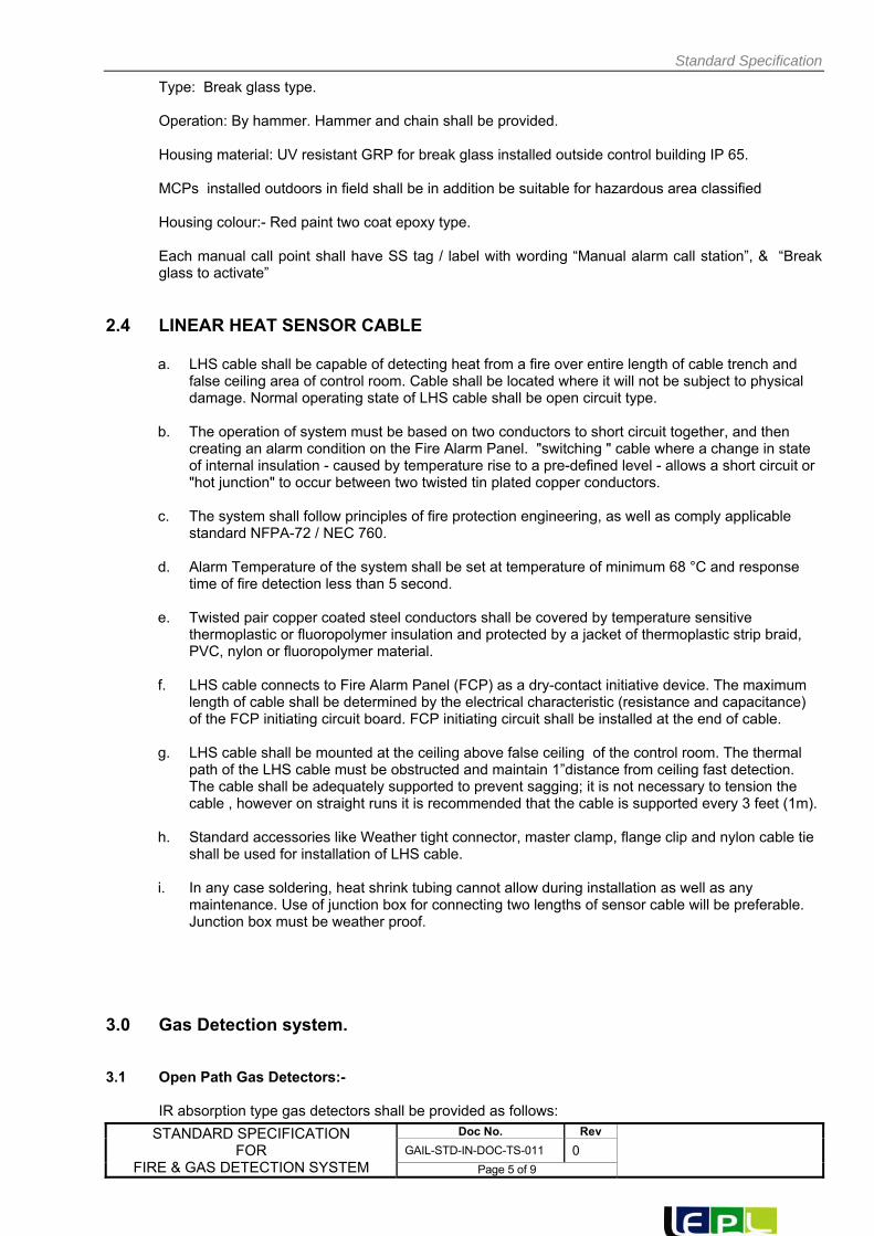
Standard Specification
STANDARD SPECIFICATION FOR
FIRE & GAS DETECTION SYSTEM
Doc No. Rev
GAIL-STD-IN-DOC-TS-011 0 Page 5 of 9
Type: Break glass type.
Operation: By hammer. Hammer and chain shall be provided. Housing material: UV resistant GRP for break glass installed outside control building IP 65. MCPs installed outdoors in field shall be in addition be suitable for hazardous area classified Housing colour:- Red paint two coat epoxy type. Each manual call point shall have SS tag / label with wording “Manual alarm call station”, & “Break glass to activate”
2.4 LINEAR HEAT SENSOR CABLE
a. LHS cable shall be capable of detecting heat from a fire over entire length of cable trench and false ceiling area of control room. Cable shall be located where it will not be subject to physical damage. Normal operating state of LHS cable shall be open circuit type.
b. The operation of system must be based on two conductors to short circuit together, and then
creating an alarm condition on the Fire Alarm Panel. "switching " cable where a change in state of internal insulation - caused by temperature rise to a pre-defined level - allows a short circuit or "hot junction" to occur between two twisted tin plated copper conductors.
c. The system shall follow principles of fire protection engineering, as well as comply applicable
standard NFPA-72 / NEC 760. d. Alarm Temperature of the system shall be set at temperature of minimum 68 °C and response
time of fire detection less than 5 second. e. Twisted pair copper coated steel conductors shall be covered by temperature sensitive
thermoplastic or fluoropolymer insulation and protected by a jacket of thermoplastic strip braid, PVC, nylon or fluoropolymer material.
f. LHS cable connects to Fire Alarm Panel (FCP) as a dry-contact initiative device. The maximum
length of cable shall be determined by the electrical characteristic (resistance and capacitance) of the FCP initiating circuit board. FCP initiating circuit shall be installed at the end of cable.
g. LHS cable shall be mounted at the ceiling above false ceiling of the control room. The thermal
path of the LHS cable must be obstructed and maintain 1”distance from ceiling fast detection. The cable shall be adequately supported to prevent sagging; it is not necessary to tension the cable , however on straight runs it is recommended that the cable is supported every 3 feet (1m).
h. Standard accessories like Weather tight connector, master clamp, flange clip and nylon cable tie
shall be used for installation of LHS cable. i. In any case soldering, heat shrink tubing cannot allow during installation as well as any
maintenance. Use of junction box for connecting two lengths of sensor cable will be preferable. Junction box must be weather proof.
3.0 Gas Detection system. 3.1 Open Path Gas Detectors:-
IR absorption type gas detectors shall be provided as follows:

Standard Specification
STANDARD SPECIFICATION FOR
FIRE & GAS DETECTION SYSTEM
Doc No. Rev
GAIL-STD-IN-DOC-TS-011 0 Page 6 of 9
2 nos detectors near each pig launcher / pig receiver 2 nos around isolation valve in SV station. 4 nos detectors around metering skid. Power supply: 24 VDC. Area classification:-Zone1,Gr IIA,IIB,T3. Weather proof protection: IP65. Out put :-4-20 ma DC. Accuracy:-+/-3% full scale. Response time:-T 95<5 secs. Range :8 LEL meters /100 meters minimum. Housing Material:- SS 316. Mounting: Swivel mounting. Lens cleaning fluid shall be supplied by contractor.
Beam blockage more than 10 secs. Shall give “BEAM BLOCKED” warning after 60 secs Shall give fault alarm. Calibration Accessories. Hand held calibrator suitable for area classified with battery and charging unit, TEST FILM etc; Tag plate :-SS 316.
3.2 Fixed Point Gas Detectors.: IR absorption type detectors shall be provided as follows: 2 nos detectors near each pig launcher/pig receiver. 2 nos around isolation valve in SV station 4 nos detectors in metering skid. Power supply: 24 V DC. Area classification :- Zone 1,Gr. II A.IIB.T3. Weather proof protection:-IP65. Detection Range:-100% LEL. Out put: 4-20 mA DC Accuracy : +/- 3% full scale. Response time : T90< 15 Secs. Housing material: SS 316. Tag plate: SS required with tag details.

Standard Specification
STANDARD SPECIFICATION FOR
FIRE & GAS DETECTION SYSTEM
Doc No. Rev
GAIL-STD-IN-DOC-TS-011 0 Page 7 of 9
Each detector shall be equipped with facilities for site calibration and testing. The detection Range shall be adjustable between 0 and 100% LEL.
3.3 Control Card and Controller for Gas Detection System shall be of OEM make only. 4.0 Field Annunciation Devices.
Alarm Beacons / Flash Lights.
Alarm beacons shall be rotating type with a coloured lens and dual high intensity halogen Bulbs. One no. red (for fire alarm) and one no. blue (for gas alarms) shall be supplied and installed at highly visible location outside control building.
5.0 Fire Alarm / Monitoring Panel and Gas Alarm / Monitoring Panel.
Fire Alarm monitoring Panel and separate Gas Alarm monitoring Panel shall be supplied and installed in each control room. This panel shall have following minimum facilities / equipment.
a) Gas Alarm / Monitoring Panel:: For gas detectors Single channel gas monitors shall be
provided with 0-100% LEL indication (LCD) ,alarms adjustable over 100% LEL range ) for low and high LEL.,AND fault alarm.(LEDs). Shall have test/acknowledge alarm, reset push buttons.
Control Card and Controller for Gas Detection System shall be of OEM make only
b) Fire Alarm / Monitoring Panel: Alarm annunciator showing zone wise fire alarms, and
remote indication for smoke Detectors installed above false ceiling and inside cable trenches.
c) A horn installed above fire /gas alarm panel, and high sound level (120 DbA) installed
Guard room.
d) The panel shall be wall mounting type suitable for safe area installation.
e) Siren with range of 1 KM shall be provided at the top of the building with acknowledge, Test and Reset provision in panel.
6.0 Portable Calibrator:
a. Portable calibrator for fixed point detectors consisting of all accessories like volume bottles, containing known gas / mixture, a pressure regulator, a flexible hose adapter cap shall be supplied to enable field calibration of the sensors/detectors without dismantling them from the field.
b. Calibration range shall be suitable for the sensors supplied, 0-100% LEL.
c. 6Sufficient quantity of calibration gas shall be supplied to enable calibration of all the
Sensors / detectors at least twice.

Standard Specification
STANDARD SPECIFICATION FOR
FIRE & GAS DETECTION SYSTEM
Doc No. Rev
GAIL-STD-IN-DOC-TS-011 0 Page 8 of 9
7.0. Area Classification
The Hazardous area classification is Zone 1, gas Group IIA/IIB, Temp. Class T3. For Certification requirement for instruments items are as below:
For all flame proof equipment / instrument / systems, which is manufactured abroad (outside India) certification by any approving authority like BASEEFA, FM, UL, PTB, LCIE. ATEX etc shall be required. For units manufactured in India certificate from CMRI will be required.
8.0 Power Supply Power supply available is 24V DC, Contractor to convert from this level to other levels.

Standard Specification
STANDARD SPECIFICATION FOR
FIRE & GAS DETECTION SYSTEM
Doc No. Rev
GAIL-STD-IN-DOC-TS-011 0 Page 9 of 9
9.0 FIRE DETECTOR ALLOCATION PLAN
Sl. no
Area Description OSD MHSD MulticriteriaHeat Detectors
MCP (Break Glass Unit)
LHS CABLE
Hooter Flashlight
ZONE
1
Control room / UPS room a) above false ceiling b) Below false ceiling
2
2
__
-
1
Zone-1 Zone-2
2
Inside cable trench in a) Control room
b) Electrical room.
__
1 1
Zone-3
3 Battery room _ 2 - Zone-4
4 Electrical Room 1 1 __ - Zone-5
5
Manual Call points (Break Glass Unit)
a) Control room
b) Electrical room
c) Store Room
d) Battery Room
__
__ 1 1 - 1
Zone-6
6. Store Room 1 Zone-7
7 Guard Room 1 Zone-8
8
Hooter + Flash Light
a) Control Room
b) Guard Room
2 -
1 1
Zone-9
OSD -- Optical Smoke Detector MHSD – Multicriteria Heat & Smoke Detectors MCP – Manual Call Point
NOTES: 1. Above mentioned numbers are tentative, However same shall be finalized during detail
Engineering. 2. Hooter / Flash lights / Beacons – Shall be different from Fire suppression system.

GAIL INDIA LIMITED
STANDARD SPECIFICATION FOR
CONTROL PANEL
GAIL-STD-IN-DOC-TS-012
0 14.01.2019 Issued As Standard RKS UNU UNU
Rev Date Purpose Prepared
By Checked
By Approved
By

Standard Specification
STANDARD SPECIFICATION FOR
CONTROL PANEL
Doc No. Rev
GAIL-STD-IN-DOC-TS-012 0 Page 2 of 9
CONTENTS
1.0 GENERAL
2.0 CONTROL PANEL CONSTRUCTION
3.0 DIMENSIONS AND MATERIAL OF CONSTRUCTION
4.0 WIRING
5.0 DELETED
6.0 BULK POWER SUPPLY UNIT
7.0 SPECIFICATIONS FOR ACCESSORIES
8.0 INDICATORS
9.0 SIGNAL DISTRIBUTION CARDS
10.0 ZENER BARRIERS/ ISOLATORS
11.0 DRAWINGS AND DATA.

Standard Specification
STANDARD SPECIFICATION FOR
CONTROL PANEL
Doc No. Rev
GAIL-STD-IN-DOC-TS-012 0 Page 3 of 9
1.0 GENERAL
1. 1 Pipeline and location of panels (Local control panel, fire alarm panel, gas alarm/monitoring panel, telecom interface panel).
1.2 Location of control panel and accessories: Indoor
1.3 Floor : Concrete Floor with Trench
1.4 Air conditioning :- YES
1.5 Control Panels Size : - Local control panel (Size 2100mmX1000mmX800mm) Wall mounted Fire and gas monitoring panels,Telecom interface panel.
(Approx size 600mmX600mmX300mm) 1.6 Contractor shall provide an alarm annunciator for fire and gas alarms, in fire and gas monitoring
panels.
2.0 CONTROL PANEL CONSTRUCTION
2.1 Type: Self supported, Free standing, enclosed cubicle.
2.2 Lighting: Required inside Panel with door switch
2.3 Ventilation: Required with louvers backed by wire fly screen & fan. Fan failure alarm required.
2.4 Doors: Rear double removable hinged doors with flush pull type handles & with locking arrangement.
2.5 Cable Entry: Bottom, Cable glands shall be single compression type. All unused entries are plugged.
2.6 Receptacles: Required for 230VAC UPS.
2.7 Painting: The finish should include sand blasting, grinding, chemical cleaning’s finishing by suitable filler and two coats of paint. Panel colour shall be Non-glossy high strain finish. Panel colour shall be RAL 7032.
2.8 Channel Base : 100*50*6 MM, MS material
2.9 Name Plates: Front of panel instrument name plates shall be black laminated plastic white core. Name plate shall be provided on rear of panel also.
3.0 DIMENSION & MATERIAL OF CONSTRUCTION
3.1 Panel Dimension: 800(w) mm X 2100(H)mm X 800(D)mm including channel base

Standard Specification
STANDARD SPECIFICATION FOR
CONTROL PANEL
Doc No. Rev
GAIL-STD-IN-DOC-TS-012 0 Page 4 of 9
3.2 Control Panels : 3.0 CRCA / 5.0 mm thick HRCA steel welded to frame
3.3 Side & Top plates : 2mm thick CRCA steel welded to frame.
3.4 Door of Panel: 1.6 mm thick CRCA steel. Rear side door shall be double door type. Concealed Hinges and Flush pull chrome plated handles.
3.5 Cable Gland Plate: 3mm thick CRCA steel
3.6 Anchor Bolt Size: By contractor
3.7 Frame: 50 mm * 50 mm * 3mm Formed section
3.8 Lifting Eye Bolt : Required
4.0 WIRING
4.1 Type : General Purpose
4.2 Wiring details (Power) 230 V AC UPS Wiring : Min, 3* 2.5 mm2 copper conductor PVC insulated armoured (Outside cabinet)
Low Voltage Inside the Cabinet: Min 19 strands,16 AWG copper conductor PVC insulated. (24V DC)
230V AC Non UPS : Min,3* 2.5 mm2 copper conductor PVC insulated armoured (outside cabinet)
4.3 Signal Wiring :
External to cabinet : 1.0 mm2 twin twisted, individual shielded/overall Shielded with overall drain PVC insulated, armoured.
Inside the cabinet : Multi strand min 1.0mm2 copper conductor PVC Insulated. Terminal Type : Screw clamp with pressure plate Terminal Size for signal : Suitable for min. 2.5mm2 size conductor.
Terminal size for power dist : Suitable for min 4.0 mm2 size conductor and higher as per actual cable sizes.
Terminal Block : Clip on type.
Wiring colour code Power supply : Hot-Red Neutral-Black Earth-green
DC Wiring : Positive-Red Negative Black Alarm System : White

Standard Specification
STANDARD SPECIFICATION FOR
CONTROL PANEL
Doc No. Rev
GAIL-STD-IN-DOC-TS-012 0 Page 5 of 9
Control and shutdown : Yellow
Analog Signals( IS ) : Light Blue
5.0 Deleted
6.0 BULK POWER SUPPLY UNIT
6.1 Input : As per Scope of Work
6.2 Output : 24V DC _+ 5 % or as required for instruments.
6.3 Rating : By Contractor 6.4 Mounting : DIN Rail mounted
6.5 Qty : 2 nos. for each Panel (Dual Redundant)
7.0 SPECIFICATIONS FOR ACCESSORIES
7.1 ALARM ANNUCIATOR No. of Window 12 (4X3) Type Solid State Mounting Flush Panel Enclosure General Purpose IP 41 Window Size 50 mm X 60 mm Make / Model No. By Contractor
Annunciator alarm sequence shall be as per F3A of ISA. The design of the alarm annunciator system shall be such that transient alarms of less than
330 milliseconds duration shall be automatically rejected. 7.2 LAMPS Type Miniature filament Rating By Contractor Voltage 24V DC Make/Model No. By Contractor Lamps shall be provided with series resistor to increase life of lamp.
7.3 Push Buttons Type Spring return Contacts 2NO + 2NC Contact Rating 2A 24V DC Make By Contractor Color As per standard
7.4 Selector Switch
Type As per functional switching and logic requirement

Standard Specification
STANDARD SPECIFICATION FOR
CONTROL PANEL
Doc No. Rev
GAIL-STD-IN-DOC-TS-012 0 Page 6 of 9
Specification Silver alloy gold plated contacts with SS shaft dust covers with water proof covering and contact shall be made before break type. Rating 2A, 24V DC Make KAYCEE/Eqv.
7.5 Relays Type Plug in relays Contact Type Potential free contact Contact nos. 3NO + 3NC Rating 24V DC , 5.0 AMP Make OEN/Eqv.
7.6 SUGGESTIVE PANEL ARRANGEMENT
1. All dimensions are in mm 2. Panel front arrangement is tentative only
Panel layout shall be designed considering ease of operation. No push button or hand switch shall be located below 600 mm. Instrument Mounting heights, in general, shall be as follows:-
a) Annunciators - 1950 mm b) Indicators - 1400 mm c) Electric push buttons / Switches, lamps etc. - 1000 mm
8.0 INDICATORS

Standard Specification
STANDARD SPECIFICATION FOR
CONTROL PANEL
Doc No. Rev
GAIL-STD-IN-DOC-TS-012 0 Page 7 of 9
8.1 Type : Single Channel Microprocessor Based Fluorescent Display with Engineering units
8.2 Mounting : Flush Panel 8.3 Enclosure : General Purpose 8.4 To be used in intrinsically safe : With exit. Zener barrier / Isolator cum Repeater System 8.5 Inputs : 4-20 mA DC (2 wires) 8.6 Outputs : 4-20 mA DC 8.7 Facia : Bar graph display of PV (with digital display) 8.8 Scan time : 500 msec. Max 8.9 A/D Convertor resolution : 1500 steps min 8.10 D/A Convertor resolution : 1500 steps min 8.11 Load driving capacity : 750 ohms 8.12 Online diagnostics : Required 8.13 Power Supply : 24V DC 8.14 QTY : AS Required
Note: One number spare indicator (dual channel) shall be provided. 9.0 SIGNAL DISTRIBUTION CARDS
9.1 Type Dual output current isolator 9.2 Input 4-20 mA DC 9.3 Output Two nos 4-20m A isolated outputs as minimum 9.4 Isolation Between input & output, Between power supply and between output and input 9.5 Accuracy _+ 0.1 % 9.6 Power Supply 24V DC 9.7 Transmitter Power 24V DC Supply 9.8 Output load driving 550ohms min for each output capacity 9.9 Qty As Required

Standard Specification
STANDARD SPECIFICATION FOR
CONTROL PANEL
Doc No. Rev
GAIL-STD-IN-DOC-TS-012 0 Page 8 of 9
10.0 ZENER BARRIERS / ISOLATORS CUM REPEATER
10.1 Type Active 10.2 Application Instrument Type
a) 4-20 m A Analog I/P from 2 wire transmiter .
b) RTD (4wire) Input output 4-20 mA analog O/P c) Limit switch ( SPDT snap acting micro type ) Output Pot. free contact d) Proximity switch (inductive type) output Pot. Free contacts e) solenoid valves 24V DC.
10.3 Hazardous Area Classification Zone 1 Gr IIA,IIB,T3
10.4 Approval FM/Basseefa/CSA/ATEX/CCOE/BIS/CMRI
10.5 Supply Volt 20-35V DC
10.6 Qty. As Required
ZENER BARRIERS/ISOLATORS CUM REPEATER AND SIGNAL DISTRIBUTION CARDS MAY BE COMBINED INTO ONE CARD.
10.7 MAKE MTL/P&F.
11.0 Drawings and Data
11.1 Detailed drawings, data, catalogues and manuals required from the vendor are indicated by the purchaser in vendor data requirement sheets. The required number of prints, soft copies and reproducible shall be provided by contractor.
11.2 Basic engineering drawings required for preparation of detail panel drawings are provided in the
tender.
11.3 Final documentation consisting of design data, installation manual, maintenance manual etc. submitted
by the contractor after placement of purchase order shall include the following, as a minimum;
a) Specification sheet for control panels, instruments and accessories.
b) Certified drawings for each control panel, which shall provide following details:
i) Control panel front arrangement drawing showing all dimensions including
bezel/cut out dimensions.
ii) Loop wiring drawings showing the terminal numbers of each instrument/
accessory used in the wiring.
iii) Ladder drawings and relay wiring drawings showing terminal numbers for
interlock/shutdown.
iv) Power supply distribution drawings with terminal numbers, incoming/
outgoing feeder size, fuse and isolator rating etc.

Standard Specification
STANDARD SPECIFICATION FOR
CONTROL PANEL
Doc No. Rev
GAIL-STD-IN-DOC-TS-012 0 Page 9 of 9
c) Contractor shall provide test certificates for all the tests as per approved QAP.
d) Calibration and maintenance procedure including replacement of instruments and
accessories in contractor’s scope, whenever it is applicable

GAIL INDIA LIMITED
STANDARD SPECIFICATION FOR PIG SIGNALLERS
GAIL‐STD‐IN‐DOC‐TS‐013
0 14.01.19 Issued for Standard RKS UNU UNU
Rev Date Purpose Prepared
By Checked
By Approved
By

Standard Specification for Pig Signalers
Doc No. Rev
GAIL-STD-IN-DOC-TS-013 0
Page 2 of 4
CONTENTS
1. SCOPE ............................................................................................................................. 3
2. MATERIALS .................................................................................................................... 3
3. DESIGN AND CONSTRUCTION REQUIREMENTS ....................................................... 3
4. INSPECTION AND TESTS .............................................................................................. 3
5. TEST CERTIFICATES ..................................................................................................... 3
6. PAINTING, MARKING AND SHIPMENT ......................................................................... 4

Standard Specification for Pig Signalers
Doc No. Rev
GAIL-STD-IN-DOC-TS-013 0
Page 3 of 4
1. SCOPE
This specification covers the basic requirements for the design and manufacture testing & supply of pig signallers, used for the detection of passage of scraper and instrumented gauging pigs, to be installed in pipeline systems handling RLNG.
2. MATERIALS
2.1 All materials used in the manufacture of the main components of the pig signalers shall be as indicated in the data sheets. Other components shall be as per manufacturer’s standard suitable for the service conditions indicated in data sheets which will be subject to approval by Purchaser.
3. DESIGN AND CONSTRUCTION REQUIREMENTS
3.1 Pig signallers shall be Bi‐directional, Non‐Intrusive, Magnetic type.
3.2 Pig signallers shall be designed to meet the requirements of pipeline diameter indicated in the data sheet.
3.3 Pig signallers shall be provided with a visual indicator to indicate the passage of pigs.
3.4 Pig signallers shall be fitted with sealed, weather‐proof and explosion proof micro switch for remote
signal indication. The area classification and rating of micro switch shall be as indicated in data sheet. Suitable for installation in IEC‐ Zone II, Gas Group‐IIA & IIB, T3 hazardous area, Micro switch shall have the following rating;
2 Amp, 240 Volts, 50 Hz, Type: SPDT,
4. INSPECTION AND TESTS
4.1 Manufacturer shall perform all inspection and tests required to supply the signallers as per the requirements of this specification.
4.2 All pig signallers shall be visually inspected.
4.3 Chemical composition & mechanical properties including hardness shall be checked for each heat of
steel used.
4.4 All welds shall be non destructively examined. 4.5 Manufacturers shall perform functional tests to establish satisfactory performance of both manual
and electrical indications.
5. TEST CERTIFICATES
5.1 Manufacturer shall supply the test certificates for material compliance as per the relevant Material Standards.
5.2 Certificate for hydrostatic test and functional test
5.3 Test reports on heat treatment carried out, if any.

Standard Specification for Pig Signalers
Doc No. Rev
GAIL-STD-IN-DOC-TS-013 0
Page 4 of 4
6. PAINTING, MARKING AND SHIPMENT
6.1 Exterior surface of the pig signallers shall be thoroughly cleaned, freed from rust and grease and applied with sufficient coats of corrosion resistant paint. Manufacturer shall indicate the type and corrosion resistant paint used in the drawings submitted for approval. The minimum dry film thickness shall be 300 microns.
6.2 A corrosion resistant metal tag shall be permanently attached with each unit, with the following
marking:‐
i) Manufacturer’s name ii) Serial No. iii) Tag No.
6.3 Each unit shall be suitably protected to avoid any damage during transit. Care shall be exercised
during packing to prevent any damage to the welding ends. All machined surfaces subject to corrosion shall be well protected by a coat of grease or other suitable materials.

0
REV
GAIL‐STD‐IN‐DOC‐DS‐001
GAIL INDIA LIMITED
DATASHEET FOR PRESSURE TRANSMITTER (PT)
Lyons Engineering Pvt. Ltd
14.01.2019 Issued for Bid RKS UNU UNU
Date Purpose of Issue Prepared By Checked By Approved By

1
2
3
4
5
6
7
8
9 20
10 21
11 22
12 23
13 24
14 25
15 26
16 a)
17 b)
18 c)
d)
19 27
1
2
3
4
5
6
7
8
9
10
11
12
1
2
3
4
5
6
7
8
9
a, c & dABU‐4002‐PT‐01001 Note 6 0 ~ 150 60 ~ 95
a, c & d
ITC‐7006‐PT‐06001B Note 6 0 ~ 150 10 ~ 19 a, c & d
98 (‐)20 ~ 65 Gas Natural Gas
98 (‐)20 ~ 65
ITC‐7006‐PT‐06001A Note 6 0 ~ 150 10 ~ 19
Gas Natural Gas
98
2 Nos cable entries shall be provided with one cable entry plugged with weather proof plug.
PRESSURE TRANSMITTERS
DOCUMENT NO. Rev.
GAIL‐STD‐IN‐DOC‐DS‐001 0
SHEET 1 of 1
NOTES:‐ (*) Vendor to furnish
Accuracy includes the combined effect of repeatability, linearity, hysterisis etc.
Operating principle of transmitters shall be capacitance / peizo resistance
Transmitter shall be Intrinsically safe.
Transmitters shall have Lightning Protection.
Transmitter Load Resistance shall be Max 600Ω @ 24 V DC
Contractor shall develop detailed datasheets with all the required information like span, make/model etc. during detailed engineering.
Manifold Shall be of Swgelok or Parker Only.
PESO/CCOE certificate for specified hazardous area classification is required with transmitters.
PIN‐4004‐PT‐04001 Note 6 0 ~ 150 10 ~ 19 98 (‐)20 ~ 65 Gas Natural Gas
a, c & dNote 6 0 ~ 150 75 ~ 95
Gas Natural Gas a, c & d
a, c & d
a, c & d
a, c & d
a, c & d
a, c & dPIN‐4004‐PT‐01001 Note 6 0 ~ 150 60 ~ 95 98 (‐)20 ~ 65 Gas Natural Gas
ABU‐4002‐PT‐04001 Note 6 0 ~ 150 04 ~ 19 a, c & d
SHI‐1276‐PT‐04001 Note 6 0 ~ 150 10 ~ 19 98 (‐)20 ~ 65
SHI‐1276‐PT‐01001
ITC‐7006‐PT‐01001 Note 6 0 ~ 150 60 ~ 95
ITC‐7006‐PT‐04001 Note 6 0 ~ 150 10 ~ 19
ITC‐7006‐PT‐01002A Note 6 0 ~ 150 10 ~ 19
Wetted Parts Material (*)
Bill of Material (BOM)
S.NO. TAG NO. Options
Span Set
Range
(Barg) Operating
Pressure (Barg)Service
Pressure (Barg)
Maximum Operating
Temperature (°C)
Fluid
Process Connection Location Bottom 2 Way manifold:‐ Yes
Diaphagram Seat (*) Model (*)
Element Materials SS 316 L Air Filler Regulator
Process Connection 1/2" NPT (F) thru flange adapter with plug. Mounting Accessories suitable for 2" NB pipe :‐ Yes
Element Diaphagram Options (*)
Body Materials SS 316 Output meter :‐ Yes (LCD in Engg. Unit)
MEASURING UNIT MISCELLANEOUS
Service Natural Gas Over Range Protection Yes
Transmitter Output 4‐20mA DC Adapter "O" ring PTFE
Load Driving Capability (*) Body Rating (*)
Accuracy "+/‐" 0.075% or better of span (Note 1)Zero Suppression &
Elevation100% of span
Repeatability 40:1 or better Zero & span adjustmentContinuously adjustable externally,
non interactive type
Power Supply (*) Capillary Length (*)
Cable Entry 1/2 " NPT(F) with SS plug Fill Fluid Silicone Oil
Enclosure WP to IP 65 as per IEC 60529 Armour Flexible (*)
Ex‐Proof NOTE ‐ 3 Armour flexible material (*)
Mounting Yoke Facing & finish (*)
Elec. Area Class. IEC Zone 1, Gr. II A/IIB, Temp. class T3 Capillary Material (*)
Type 2 Wire, Electronic smart transmitter with HART Protocol. Process Connection (*)
Case Mfr. Std. Size & Rating (*)
CLIENT:
QUANTITY: AS PER P&ID
Function Transmission & Indication Other Material (*)
Natural Gas
98 (‐)20 ~ 65 Gas Natural Gas
98 (‐)20 ~ 65 Gas Natural Gas
98 (‐)20 ~ 65 Gas
(‐)20 ~ 65 Gas Natural Gas
98 (‐)20 ~ 65 Gas Natural Gas
98 (‐)20 ~ 65 Gas Natural Gas
ITC‐7006‐PT‐01002B Note 6 0 ~ 150 10 ~ 19 98 (‐)20 ~ 65 Gas Natural Gas a, c & d

GAIL‐STD‐IN‐DOC‐DS‐002
0
REV Lyons Engineering Pvt. Ltd
14.01.2019 Issued for Bid RKS UNU UNU
Date Purpose of Issue Prepared By Checked By Approved By
GAIL INDIA LIMITED
DATASHEET FOR TEMPERATURE TRANSMITTER (TT)

CLIENT:
1
2
3
4
5
6
7
8
9
10
11
12
13
14
15
16
17
18
19
1
2
3
4
5
6
7
8
9
10
11
12
1)
2)
3)
4)
5)
(‐) 20 ~ 65 Natural Gas a,b
Natural Gas a,b
PIN‐4004‐TT‐01001 Note 5 (‐) 20 ~ 100 20 (‐) 20 ~ 65 Natural Gas a,b
20
20
20
20
SHI‐1276‐TT‐01001 Note 5 (‐) 20 ~ 100 20
SHI‐1276‐TT‐04001 Note 5 (‐) 20 ~ 100 20
PIN‐4004‐TT‐04001 Note 5 (‐) 20 ~ 100 20
QUANTITY: AS PER P&ID
Function Transmission & Indication
Elec. Area Class. IEC Zone 1, Gr. II A/IIB, Temp. class T3
Enclosure WP to IP 65 as per IEC 60529 / IS 2147
Intrinsically Safe Yes
Type 2 Wire, Electronic smart transmitter with HART Protocol.
Case Mfr. Std.
Mounting Yoke & Remote
Self Diagnostic Facility Yes
Cold Junction Compensation (*)
Transmitter Output 4‐20 mA DC
Power Supply 24 VDC, 2 Wire
Cable Entry 1 Nos 1/2" NPTF for output signal + 1 Nos. 1/2" or 3/4" NPTF for RTD signal wire
Accuracy ±0.18º or better of span
Options (*)
Mount. Accessories for 2" NB Pipe Yes
Integral output meter Yes (In engg. Unit)
Load Capability (*)
Sensor Element (*)
Calibration As per DIN 43760
a)
b)
Model (*)
Quantity (*)
Bill of Material (BOM)
S.NO. TAG NO.Temperature (°C)
SERVICE OPTIONSDesign (Max)
Range (°C)
Adustable Operating (Nor)Set
ITC‐7006‐TT‐01001 Note 5 (‐) 20 ~ 100 (‐) 20 ~ 65 Natural Gas a,b
ITC‐7006‐TT‐04001 Note 5 (‐) 20 ~ 100 (‐) 20 ~ 65 Natural Gas a,b
20
20
ITC‐7006‐TT‐01002A Note 5 (‐) 20 ~ 100 (‐) 20 ~ 65 Natural Gas a,b
ITC‐7006‐TT‐01002B Note 5 (‐) 20 ~ 100 (‐) 20 ~ 65 Natural Gas a,b
20
20
Natural Gas a,bITC‐7006‐TT‐06001A Note 5 (‐) 20 ~ 100 (‐) 20 ~ 65
ABU‐4002‐TT‐04001 Note 5 (‐) 20 ~ 100 (‐) 20 ~ 65
Natural Gas a,b
ITC‐7006‐TT‐06001B Note 5 (‐) 20 ~ 100 (‐) 20 ~ 65 Natural Gas a,b
ABU‐4002‐TT‐01001 Note 5 (‐) 20 ~ 100 (‐) 20 ~ 65 Natural Gas a,b
Natural Gas a,b
TEMPERATURE TRANSMITTERS
DOCUMENT NO. Rev.
GAIL‐STD‐IN‐DOC‐DS‐002 0
SHEET 1 of 1
NOTES:‐ (*) Vendor to furnish
PESO/CCOE certificate for specified hazardous area classification is required with transmitters.
Transmitters shall have Lightning Protection.
Transmitter Load Resistance shall be Max 600Ω @ 24 V DC
Temperature transmitter shall be dual compartment type.
Contractor shall develop detailed datasheets with all the required information like span, make/model etc. during detailed engineering.
(‐) 20 ~ 65
(‐) 20 ~ 65

GAIL‐STD‐IN‐DOC‐DS‐003
0
REV Lyons Engineering Pvt. Ltd
14.01.2019 Issued for Bid RKS UNU UNU
Date Purpose of Issue Prepared By Checked By Approved By
GAIL INDIA LIMITED
DATASHEET FOR TEMPERATURE ELEMENT (RTD) WITH THERMOWELL

1 12
2 13
3 14
4
5 15
6 16
7 17
8 18
20
21
9
10
11
1
2
3
4
5
6
7
8
9
10
11
12
1)
2)
3)
4)
RESISTANCE TEMPERATURE DETECTORS (RTD) WITH THERMOWELL
DOCUMENT NO. Rev.
GAIL‐STD‐IN‐DOC‐DS‐003 0
SHEET 1 of 1
NOTES:‐ (*) Vendor to furnish
Element length shall be suitable for thermowell.
Thermowell immersion length shall be selected in such a way that tip of thermowell shall preferably be at the centre of pipe to sense temperature properly.
RTD element shall be 4‐wire, duplex type, Class A tolerance, Pt‐100
Vendor to furnish GAD of complete assembly (TG with T/W), WFC Calculation as per the latest PTC 19.3.
ABU‐4002‐TE‐04001 (‐) 20 ~ 65 SS 316L
ABU‐4002‐TE‐01001 (‐) 20 ~ 65 SS 316LNote 1 20 (*) (*)
Note 1 20 (*) (*) (*) Natural Gas
ITC‐7006‐TE‐06001B (‐) 20 ~ 65 SS 316L
ITC‐7006‐TE‐06001A (‐) 20 ~ 65 SS 316LNote 1 20 (*) (*) (*) Natural Gas
Note 1 20 (*) (*) (*) Natural Gas
(*) Natural Gas
ITC‐7006‐TE‐01002B (‐) 20 ~ 65 SS 316L
ITC‐7006‐TE‐01002A (‐) 20 ~ 65 SS 316L
Note 1 20 (*) (*)
Note 1 20 (*) (*) (*) Natural Gas
(*) Natural Gas
ITC‐7006‐TE‐04001 (‐) 20 ~ 65 SS 316L
ITC‐7006‐TE‐01001 (‐) 20 ~ 65 SS 316LNote 1
Note 1 20 (*)
(*) (*) (*) Natural Gas20
(*) (*) Natural Gas
S.NO. TAG NO. Options
Design (Max)
Element Length
Operating (Nor)
Thermowell
N T L
Bill of Material (BOM)
Temperature (°C)
Material
Dimension Service
MEASURING UNIT
Head Cover Type Screw Cap of Die Cast Aluminium with SS chain
No. of Wires Four Wires b)
HEAD c)
b) Material SS 316 Options (*)
Nipple & Union Material SS 316 a)Extra nipple
extents150 mm
Sheath (*) Inst. Connection 1/2" NPT
a) O.D. 8 mm Thermowell Dwg
Resistance at 0 deg. Celsius 100 Ω Construction
Drilled bar stock upto imme‐
rsion length 500 mm,
otherwise fabricated
Leads Hermatically Sealed Process Connection 2" But‐Weld
Calibration As per DIN 43760 / IEC 60751 THERMOWELL
Element Material Pt‐100, Class A Material SS 316
Element 4 Wire RTD Class A type No. of Entries Two
No. of Elements Duplex Enclosure TypeWP to IP 65 as per IEC 60529
/ IS 2147 and Ex‐Proof (IS 2148)
CLIENT:
QUANTITY: AS PER P&ID
Assembly As per drawing Cable Entry 1/2" NPT
SHI‐1276‐TE‐04001 Note 1 20 (‐) 20 ~ 65 SS 316L (*) (*) (*) Natural Gas
SHI‐1276‐TE‐01001 Note 1 20 (‐) 20 ~ 65 SS 316L (*) (*) (*) Natural Gas
PIN‐4004‐TE‐04001 Note 1 20 (‐) 20 ~ 65 SS 316L (*) (*) (*) Natural Gas
PIN‐4004‐TE‐01001 Note 1 20 (‐) 20 ~ 65 SS 316L (*) (*) (*) Natural Gas

0
REV Lyons Engineering Pvt. Ltd
14.01.2019 Issued for Bid RKS UNU UNU
Date Purpose of Issue Prepared By Checked By Approved By
GAIL‐STD‐IN‐DOC‐DS‐004
GAIL INDIA LIMITED
DATASHEET FOR GAS DETECTOR

CLIENT:
1
2
3
4
5
6
7
8
9
10
11
12
13
14
15
16
17
18
19
20
21
22
23
24
25
26
27
28
29
S.NO.
1
2
3
4
5
6
7
8
9
10
11
12
1)
2)
14.01.2019
PINSHI‐4004‐GDPA‐01002 Point Gas Detector
Protection IP 65 as per IEC 60529
Accuracy ± 2% LEL
SHI‐1276‐GDPA‐01002 Point Gas Detector
PINSHI‐4004‐GDPA‐01001 Point Gas Detector
High concentration alarm Required
TAG NO. Type of Gas Detector
Point Gas Detector
ITC‐7006‐GDPA‐06002 Point Gas Detector
ABU‐4002‐GDPA‐01001 Point Gas Detector
ABU‐4002‐GDPA‐01002 Point Gas Detector
SHI‐1276‐GDPA‐01001 Point Gas Detector
Not Required
(*)
QUANTITY: AS PER P&ID
Tag Number Refer below BOM
Ambient Tempertaure 25 ~ 30°C
Electrical Certification Intrinsically Safe(Ex 'ia') or Ex 'd'
IR basedTechnology
GIGL‐ENG‐7006‐PR‐DWG‐PID‐002/003/007/011/013P&ID Number
Zone‐1, Div. 1, Group IIA & IIB, T3Hazardous area Classification
12 Nos.Qty.
Required
Housing material Stainless steel 316, Flameproof
Low Explosive Limit (LEL) 1 (% v/v in Air)
Range 0 ~ 100% LEL and Detection Range upt 15 feet.
Cable Entry 3/4" NPTF
Immunity to catalytic poisoning Required
Temperature compensation
Output 4~20 mA DC HART
Power supply 24V DC
Type of wiring 3‐Wire
Response time Less than T90 < 12 sec
Sensor life 5 Years
Self diagnostic facility Required
Fail safety Required
Mounting Accessories Refer Note 2
Dustguard & Splashguard Required
Integral meter Digital LED type
Make (*)
Bill of Material (BOM)
Remarks
High concentration switch
Model No.
ITC‐7006‐GDPA‐01001 Point Gas Detector
ITC‐7006‐GDPA‐01002 Point Gas Detector
ITC‐7006‐GDPA‐01003 Point Gas Detector
ITC‐7006‐GDPA‐01004 Point Gas Detector
POINT GAS DETECTOR
DOCUMENT NO. Rev.
GAIL‐STD‐IN‐DOC‐DS‐004 0
SHEET 1 of 3
NOTES:‐ (*) Vendor to furnish
Instrument shall be tested by any recognised authority like BASEEFA, FM, PTB, CMRI etc. and certified by Petroleum and Explosives Safety Organisation (PESO) / Chief Controller of Explosives (CCOE)
in india.
Mounting Brackets shall be suitable to 2" pipe mounting.The bolts and nuts shall be alloy steel as per ASTM A193 Gr. B7 and ASTM A194 Gr. 2H (Hot dipped Galvanized or zinc Plated) respectively.
Other accessories shall be zinc Plated.

CLIENT:
1
2
3
4
5
6
7
8
9
10
11
12
13
14
15
16
17
18
19
20
21
22
23
24
25
26
27
28
29
S.NO.
1
2
3
4
5
6
7
8
9
10
11
12
1)
2)
3)
4)
OPEN PATH GAS DETECTOR
DOCUMENT NO. Rev.
GAIL‐STD‐IN‐DOC‐DS‐004 0
SHEET 2 of 3
NOTES:‐ (*) Vendor to furnish
Instrument shall be tested by any recognised authority like BASEEFA, FM, PTB, CMRI etc. and certified by Petroleum and Explosives Safety Organisation (PESO) / Chief Controller of Explosives
(CCOE) in india.
Mounting Brackets shall be suitable to 2" pipe mounting.The bolts and nuts shall be alloy steel as per ASTM A193 Gr. B7 and ASTM A194 Gr. 2H (Hot dipped Galvanized or zinc Plated) respectively.
Other accessories shall be zinc Plated.
Detector able to operate even when obscured by fog, rain, dust, snow or blowing sand.
Detector shall be based on Transmitter module & Receiver Module.
PINSHI‐4004‐AE(T/R)‐01002 Open Path Gas Detector
SHI‐1276‐AE(T/R)‐01002 Open Path Gas Detector
PINSHI‐4004‐AE(T/R)‐01001 Open Path Gas Detector
ABU‐4002‐AE(T/R)‐01002 Open Path Gas Detector
SHI‐1276‐AE(T/R)‐01001 Open Path Gas Detector
ITC‐7006‐AE(T/R)‐06002 Open Path Gas Detector
ABU‐4002‐AE(T/R)‐01001 Open Path Gas Detector
ITC‐7006‐AE(T/R)‐01004 Open Path Gas Detector
14.01.2019 Open Path Gas Detector
ITC‐7006‐AE(T/R)‐01002 Open Path Gas Detector
ITC‐7006‐AE(T/R)‐01003 Open Path Gas Detector
Bill of Material (BOM)
TAG NO. Type of Gas Detector Remarks
ITC‐7006‐AE(T/R)‐01001 Open Path Gas Detector
High concentration switch Not Required
Model No. (*)
Make (*)
Dustguard & Splashguard Required
Integral meter Digital LED type
High concentration alarm Required
Self diagnostic facility Required
Fail safety Required
Mounting Accessories Refer Note 2
Cable Entry 3/4" NPTF
Response time Less than T90 < 5 sec
Sensor life 5 Years
Output 4~20 mA DC HART
Power supply 24V DC
Type of wiring 3‐Wire
Protection IP 65 as per IEC 60529
Technology IR based (Transmitter & Receiver type)
Accuracy ± 2% LEL
Immunity to catalytic poisoning Required
Temperature compensation Required
Housing material Stainless steel 316, Flameproof
Low Explosive Limit (LEL) 1 (% v/v in Air)
Range 0 ~ 100% LEL and Detection Range 5 to 100 mtrs.
QUANTITY: AS PER P&ID
Tag Number Refer below BOM
Ambient Tempertaure 25 ~ 30°C
Electrical Certification Intrinsically Safe(Ex 'ia') or Ex 'd'
GIGL‐ENG‐7006‐PR‐DWG‐PID‐002/003/007/011/013P&ID Number
Zone‐1, Div. 1, Group IIA & IIB, T3Hazardous area Classification
12 Nos.Qty.

DATA SHEET ‐
IR TYPE PORTABLE GAS DETECTOR
CLIENT:
DOCUMENT NO. Rev.
0GAIL‐STD‐IN‐DOC‐DS‐004
SHEET 3 of 3
25 Accessories Travel Charger, AC Adapter, Calibration Adapter
Note: (*) Vendor to furnish
1. Required certificates has to be submitted by Contractor.
23 Dimensions
24 Mounting
21 Storage Temp. Range ‐ 20 to 50 deg C
MECHANICAL CHARACTERSTICS
22 Total Weight
19 Operating Humidity 0 to 95% RH (Non‐Condensing)
20 Operating/Ambient Temp. Range ‐ 20 to 50 deg C
ENVIRONMENTAL PROTECTION
17 Hazardous Area Classification II 2G Ex ia d IIC T4 Gb
18 Ingress Protection IP 65
17 Calibration
Pre‐Calibrated with Methane (Valid Calibration Certificate
shall be provided).
O2 (with valid calibration certificates).
18 Self Test & Diagnostics Fitted
15 Monitoring Object Natural Gas Leak, O2
16 Calibration Gas Methane
13 Alarms
Multi‐tone audible (95 db @30 cm), Vibration, Visible
(flashing bright red LEDs), on‐screen indication of alarm
conditions and Man Down Alarm with pre‐alarm.
14 Datalogging
Continuous datalogging (six months for 5 sensors at 1‐
minute intervals, 24/7) or User configurable datalogging
interval (from 1 to 3600 seconds).
11 Display
Monochrome graphical LCD display (128 X 160) with
backlighting (activated automatically in dim ambient
lighting conditions when monitor is in alarm or with a
button press), Automatic screen flipping.
12 Display Readout
Real‐time reading of gas concentrations; battery status;
datalogging on/off; STEL, TWA, Peak, and minimum
values, Various instrument status related information.
9 Response Time ≤ 15 Secs.
10 Battery Rechargeable Li‐ion Type, Battery back up time is 18
hours and recharge time is < 6 hours.
7 Detector Range 0 to 100% Vol. CH4, 0‐30% vol. O2
8 Warm Up Time Less than 5 Mins.
DETECTOR CHARACTERSTICS
5 Sensor Type Non‐Dispresive Type IR Absorption
6 Detection Method Diffusion Type
TECHNICAL DATA SHEET
‐ IR TYPE PORTABLE GAS DETECTORQUANTITY ‐ AS PER REQUIREMENT
Sr No. Parameter Typical requirements
3 Part No. (*)
4 Quantity 5 Nos.
GENERAL CHARACTERSTICS
1 Manufacture (*)
2 Model (*)

0
REV
GAIL INDIA LIMITED
DATASHEET FOR PRESSURE GAUGES (PG)
GAIL‐STD‐IN‐DOC‐DS‐005
Lyons Engineering Pvt. Ltd
14.01.2019 Issued for Bid RKS UNU UNU
Date Purpose of Issue Prepared By Checked By Approved By

CLIENT:
1
2
3
4
5
6
7
8
9
10 17
11 18
12 19
13 a) b)
14 c) d)
e) f)
15 g)
16
1
2
3
4
5
6
7
8
9
10
11
12
13
14
15
16
17
18
19
0 ~ 100 c, d, f, g
MDR-4003-PG-06002 0 ~ 160
c, d, f, gABU-4002-PG-07001 0 ~ 100
c, d, f, g
ABU-4002-PG-18001 0 ~ 100 c, d, f, g
ABU-4002-PG-15002 0 ~ 100
c, d, f, g
ABU-4002-PG-06001
c, d, f, g
ABU-4002-PG-15001 0 ~ 100 c, d, f, g
04 ~ 19 49
ITC-7006-PG-09001 0 ~ 160 c, d, f, g
ITC-7006-PG-09002 0 ~ 160 c, d, f, g
MDR-4003-PG-01001 0 ~ 160 c, d, f, g
98 (-) 20 ~ 65°C Gas Natural Gas
MDR-4003-PG-06001 0 ~ 160 c, d, f, g
60 ~ 95 98 (-) 20 ~ 65°C Gas Natural Gas
60 ~ 95 98 (-) 20 ~ 65°C Gas Natural Gas
(-) 20 ~ 65°C Gas Natural Gas
04 ~ 19 49 (-) 20 ~ 65°C
Mounting Local Other Material
Colour White with black inscription Size & rating
Pressure Element Bourdon Flushing/filling connection with
Accuracy "+/-" 1% of FSD Options
Zero Adjustment Micropointer - External Type Scrubber Syphon
Element Material
(*)
Dial Size 150 mm Process Connection 1/2"
QUANTITY: AS PER P&ID
Type Direct Wetted Parts Material (*)
(*)
Case Material SS 316 Facing & finish (*)
Enclosure WP to IP 65 as per IEC 60529/IS 2147 Capillary Length (*)
(*)
Bezel Ring Beyonnet type SS 316 Capillary Material (*)
Window Material Shatterproof glass Armour Flexible Material (*)
SS 316 Over range protection 130 % of FSD
Socket Material SS 316 Blow out protection Yes
Connection 1/2" NPT(M) Gauge Saver Liquid filled casing
Connection location Bottom Vaccum protection Solid front
Type (*)
Bill of Material (BOM)
Sl. No. Tag No.Range (Barg)
Movement SS 316 Three valve manifold Yes (*)
Diaphagram Seat Rigid
c, d, f, g
ITC-7006-PG-01003B 0 ~ 160
ITC-7006-PG-01003A 0 ~ 160
c, d, f, gGas Natural Gas
Options
0 ~ 01 98 (-) 20 ~ 65°C
c, d, f, g
ITC-7006-PG-06001 0 ~ 160 c, d, f, g
10 ~ 19 98 (-) 20 ~ 65°C Gas Natural Gas
10 ~ 19 98 (-) 20 ~ 65°C Gas Natural Gas
ITC-7006-PG-01002A 0 ~ 160
0 ~ 100
ITC-7006-PG-06002B 0 ~ 160 0 ~ 01 98 (-) 20 ~ 65°C Gas Natural Gas
c, d, f, g
ITC-7006-PG-06002A 0 ~ 160 c, d, f, g
10 ~ 19 98 (-) 20 ~ 65°C Gas Natural Gas
10 ~ 19 98 (-) 20 ~ 65°C Gas Natural Gas
ITC-7006-PG-06002 0 ~ 160
c, d, f, g
ABU-4002-PG-07002 0 ~ 100 c, d, f, g
ABU-4002-PG-13002
Operating Pressure
(Barg)
Maximum Service
Pressure (Barg)
Temperature (°C)
Fluid Service
Gas Natural Gas10 ~ 19 98 (-) 20 ~ 65°C
0 ~ 01 98 (-) 20 ~ 65°C Gas Natural Gas
0 ~ 01
12 ~ 19 98 (-) 20 ~ 65°C Gas Natural Gas
04 ~ 19 49 (-) 20 ~ 65°C Gas Natural Gas
04 ~ 19 49 (-) 20 ~ 65°C Gas Natural Gas
04 ~ 19 49 (-) 20 ~ 65°C Gas Natural Gas
Gas Natural Gas
04 ~ 19 49 (-) 20 ~ 65°C Gas Natural Gas
04 ~ 19 49 (-) 20 ~ 65°C Gas Natural Gas

20
21
22
23
24
25
26
1)
2)
3)
PIN-4004-PG-06002 0 ~ 160 c, d, f, g
c, d, f, g
SHI-1276-PG-06002 0 ~ 160 c, d, f, g
SHI-1276-PG-06001 0 ~ 160
PIN-4004-PG-06001 0 ~ 160 10 ~ 19 98 (-) 20 ~ 65°C Gas Natural Gas c, d, f, g
c, d, f, g
ABU-4002-PG-08002 0 ~ 100 c, d, f, g
ABU-4002-PG-08001 0 ~ 100
04 ~ 19 49 (-) 20 ~ 65°C Gas
ABU-4002-PG-18002 0 ~ 100 c, d, f, g
NOTES:- * Vendor to furnish
Gauge Saver shall be provide with Low Pressure Gauges on Pig Launcher & Receiver.
Manifold shall be of Swgelok or Parker Only.
Contractor shall develop detailed datasheets with allthe required information like make/model etc during detailed engineering.
04 ~ 19 49 (-) 20 ~ 65°C Gas Natural Gas
04 ~ 19 49 (-) 20 ~ 65°C Gas Natural Gas
PRESSURE GAUGE
10 ~ 19 98 (-) 20 ~ 65°C Gas Natural Gas
Natural Gas
10 ~ 19 98 (-) 20 ~ 65°C Gas Natural Gas
10 ~ 19 98 (-) 20 ~ 65°C Gas Natural Gas
DOCUMENT NO. Rev.
GAIL-STD-IN-DOC-DS-005 0
SHEET 2 of 2

0
REV Lyons Engineering Pvt. Ltd
14.01.2019 Issued for Bid RKS UNU UNU
Date Purpose of Issue Prepared By Checked By Approved By
GAIL‐STD‐IN‐DOC‐DS‐006
GAIL INDIA LIMITED
DATASHEET FOR TEMPERATURE GAUGES (TG)

1 17
2 18
3 19
4
5
6
7 20
8
9 21
10 21
11 22
23
12 24
25
26
27
13 a)
b)
14 c)
15
16
1
2
3
4
5
6
7
8
9
U
T
1)
2)
20°C (*) (*)
(*)
(*) (*)
(*) (*)
20°C (*) (*)
20°C (*) (*)
PIN-4004-TG-06002 (-) 20°C ~ 100°C (-) 20°C ~ 65°C (*) Natural Gas
SHI-1276-TG-06002 (-) 20°C ~ 100°C (-) 20°C ~ 65°C (*)
20°C
Natural Gas
ABU-4002-TG-18001 (-) 20°C ~ 100°C (-) 20°C ~ 65°C (*)20°C
Natural Gas
Well Required Bulb diameter To suit thermowell
Mounting Local Capillary MaterialWP to IP 65 as per IEC 60529/IS 2147
Dial Size 150 mm Armour flexible (*)
QUANTITY: AS PER P&ID
Type Bimetalic Extension Type Rigid
CLIENT:
Armour Material (*)
Conn. Location Bottom THERMOWELL
Accuracy "+/-" 1% of FSD Material SS 316
Case Material Cast Aluminium Capillary Length (*)
Window Material Shatter proof glass Over Range protection
Colour White with black inscription
BIMETAL Process Connection Welded
Stem Gauge Connection 1/2" NPT(F)
Enclosure WP to IP 65 as per IEC 60529 / IS 13947 Options (*)
Zero adj. screw Required External Type ConstructionDrilled bar stock upto immersion length 500mm, otherwise fabricated
Type (*) Thermowell Dwg. (*)
Material (*) Over Range protection (*)
Filled System (*)
SAMA class V
Size (*) Options (*)
Stem Diameter (*) Liquid Filled Yes
Bulb Material SS 316
Bulb Union Threaded to 1/2" NPT(M)
Compensation Case
Bulb Type Adjustable Union
Bill of Material (BOM)
Temperature (°C) Thermowell
DimensionSl. No. Tag No.
ITC-7006-TG-09001 (-) 20°C ~ 100°C (-) 20°C ~ 65°C
RangeOperating (Nor) Design (Max) Material
N T L
Service Options
MDR-4003-TG-06001 (-) 20°C ~ 100°C (-) 20°C ~ 65°C
(-) 20°C ~ 65°C
20°C
20°C
20°C
(*) Natural Gas
(*) Natural Gas
Natural Gas
(*) (*)
20°C (*) (*)
(*) (*)
(*) (*)
(*) Natural GasABU-4002-TG-06002 (-) 20°C ~ 100°C (-) 20°C ~ 65°C
ABU-4002-TG-07001 (-) 20°C ~ 100°C
ABU-4002-TG-15001 (-) 20°C ~ 100°C (-) 20°C ~ 65°C (*) Natural Gas
Natural Gas
ABU-4002-TG-08001 (-) 20°C ~ 100°C (-) 20°C ~ 65°C (*)
DOCUMENT NO. Rev.
GAIL-STD-IN-DOC-DS-006 0
SHEET 1 of 1
NOTES:- (*) Vendor to furnish
Immersion length
Lagging Extension
Element length shall be suitable for thermowell.
U-length shall be selected in such a way that the thermowell tip shall be preferably at the centre of pipe to sense the temperature accurately.
TEMPERATURE GAUGE

0
REV Lyons Engineering Pvt. Ltd
14.01.2019 Issued for Bid RKS UNU UNU
Date Purpose of Issue Prepared By Checked By Approved By
GAIL‐STD‐IN‐DOC‐DS‐007
GAIL INDIA LIMITED
DATASHEET FOR PRESSURE SAFETY VALVE (PSV)

1 Tag No. Quantity ITC‐7006‐PSV‐01001 / 06001 2 nos.2 Line No. Schedule X"‐NG‐01013‐6D1‐P / X"‐NG‐06010‐6D1‐P 600# / 150#3 Vessel No. ITC‐7006‐PL‐01001 / ITC‐7006‐PR‐060014 Safety / Relief Pressure Safety Valve5 Full Nozzle Full Lift/Mod. Nozzle Full nozzle full lift6 Bonnet type Closed7 Conv./Bellows/Pilot Operated Conventional8 Inlet Conn. Size & Rating As per P&ID9 Facing & Finish *10 Outlet Conn. Size & Rating As per P&ID11 Facing & Finish *12 Cap Over Adj. Bolt Yes13 Screwed / Bolted Bolted14 Lifting Gear ‐ Type15 Test Gag Yes16 Lever(Plain/Packed) *1718 Body and Bonnet A352 Gr LCC / A 350 LF2 / A 351 CF8M19 Nozzle and Disc SS31620 Spring As per API 52621 Bellows ‐‐222324 Resilient Seat Seal ‐‐
252627 Code ASME / API
282930 Fluid State Natural Gas Gas31 Corrosive Constituent32 Required Flow Capacity 0.578 MMSCMD
33 Mol.Wt. S.G. at Rel. Temp 17.95
34 Oper. Pressure Normal 10 ~ 19
35 Oper. Temp. Rel. Temp. (‐) 20 ~ 65°C
36 Valve Discharges to Atmosphere
37 Back Press. Const. Or Variable Constant
38 Set Pressure (Barg) 98
39 Cold Bend Test Pressure
40 % Over Pressure % Blow Down As per API / ASME
41 Cp/Cv (k) Compressibility Factor 1.29% 0.97
42 Viscosity @ Rel. Temp. mPas(cP)
43 Vess. Wall Temp. Surf.Area‐m2
44 Max & Min Pressure (Barg) 10 ~ 19
45 Calculated Area cm2 *
46 Sel. Area cm2 Orifice Design * *
47 No. of Valves Reqd. for capacity *
48 Tota Area ‐ cm2 *
49 Actual Flow Capacity *
50
51 Model No. *
52 CCOE Yes
53 Radiography
54 ASME UV/NB Yes
NOTES:
'*' : Vendor to furnish
1 At the time of approval, vendor shall furnish sizing calculation and catalogues of PSV.
2 Test GAG Required for safety valve & Pressure Safety valve shall be fire case type.
3 Vendor to submit Sizing sheet, Model Decodifiation sheet, Catalogue,Drawings and QAP for approval.
Basis
CLIENT:
QUANTITY: As Per P&ID
PSV
UNITS: Flow<‐> Liquid‐ m*3/hr Gas‐ Sm*3/hr Steam‐ kg/hr Pressure‐>Barg Temperature<‐> Deg C Level/Length<‐> mm
General
Valve
Material
Options
Service
conditions
21%
Orifice
100%
Data Sheet of Pressure Safety ValveDOCUMENT NO. Rev.
GAIL‐STD‐IN‐DOC‐DS‐007 0

0
REV
GAIL INDIA LIMITED
DATASHEET FOR SCRAPPER/PIG SIGNALLER/DETECTOR ‐ INTRUSIVE
TYPE
GAIL‐STD‐IN‐DOC‐DS‐008
Lyons Engineering Pvt. Ltd
14.01.2019 Issued for Bid RKS UNU UNU
Date Purpose of Issue Prepared By Checked By Approved By

1
2
3
4
5
6
7
8
9
10
11
12
13
14
15
16
17
18
19
20
21
22
23
24
25
26
27
28
29
30
31
32
33
34
35
36
37
38
39
Max.
1
2
3
4
1
2
3
4
5
(*) To be provided by Vendor.
Pig Signallers shall be with isolation valve (Full Bore) for On‐line repair. Valve material shall be LTCS.
Visual Indicator with manual reset shall be provided.
ITC Food Park ‐ Kapurthala (New
Receiving TerminalITC‐7006‐XXS‐06002 ITC‐7006‐PR‐06001
NOTES:‐
ITC Food Park ‐ Kapurthala (New
Receiving TerminalITC‐7006‐XXS‐06001 6"‐NG‐06005‐X52‐P
Sr. No. Station No. Tag No. Line Size
Normal Max.
Line Gas pressure (barg)
Normal
Bill of Material(BOM)
Required
Sensing Elemen
t
Jacking bracket for removal of scraper detector Required
Switch
Barrel Specification
Others
Setting Adjustable (Factory set for Scrapper passage/detection signal)
Body Material ASTM A 350 LF 2
Corrosion Allowance 1.6 mm
Potential free contact SPDT (2 NOS.)/ DPDT (1 NO.)
Mounting On Above Ground Pipe
By Vendor
Welded on Scrapper Barrel
DATASHEET FOR SCRAPPER/PIG SIGNALLER/DETECTOR ‐ INTRUSIVE TYPE
DOCUMENT NO. Rev.
GAIL‐STD‐IN‐DOC‐DS‐008 0
SHEET 1 of 1
Gen
eral
Process Condition
Pig Details
Detection Speed
Connection
Internals SS 316 or better
Type of neck Short neck
Body enclosure Anti‐corrosive epoxy painted
Enclosure type EEx 'd', IP 65
Electrical Entry 1/2” NPTF(Note‐3)
Signal Output
Material Compliance as per EN 10204 3.2 Certificate.
Painting shall be suitable for Corrosive Industrial environment.
Response Time (*)
Type Limit switch / Proximity Switch Hermatically sealed; auto reset (restores to normal Position after actuation). Make – As per vendor list
Contact Rating 24 VDC, 2A
Operating temp (°C)Remarks
Pipeline Diameter (NB) 6"
Pipeline wall Material API 5L Gr. (PSL‐2) X‐52
Wall Thickness (mm) 6.4 mm (Main Pipeline)
Min. Pipeline Coating Thickness (External‐3 Layer
Polyethylene)Minimum 2.7 mm
Local Indicator Mechanical visual (flag) with manual reset
Local Reset Buton Black Colour, Eexd, IP65
Ball valves for removing scraper detector for servicing
Existing SV ‐ 7006 of BJPL (New
Despatch TerminalITC‐7006‐XXS‐01002 6"‐NG‐01019‐X52‐P
Existing SV ‐ 7006 of BJPL (New
Despatch TerminalITC‐7006‐XXS‐01001 ITC‐7006‐PL‐01001
Multiphase Product No
Process Fluid Natural Gas
Gas Temperature (Design) (‐)20~60 (Under Ground); (‐)20~65 (Above Ground)
Line gas Pressure (Design) (*)
Area Classification Zone‐2, IIA/IIB T3
Pig Diameter (O. D.) 95% ~ 100 % of Pipeline ID
Pig Velocity (Max.) 8 m/Sec
Type Intrusive (Bi‐directional)
Pig Material Carbon Steel (*)
Pig Length (*)
QUANTITY: AS PER P&ID
Tag No. & Quantity As per BOM below
Ambient temp. 0°C ~55°C
Relative Humidity 0.98
CLIENT:
Make (*)
Model (*)
Service Outdoor,unprotected

0
REV
GAIL INDIA LIMITED
DATASHEET FOR GAS OVER OIL ACTUATOR VALVES (GOOV)
GAIL‐STD‐IN‐DOC‐DS‐009
Lyons Engineering Pvt. Ltd
14.01.2019 Issued for Bid RKS UNU UNU
Date Purpose of Issue Prepared By Checked By Approved By

Doc. No. GAIL‐STD‐IN‐DOC‐DS‐009 Page 1 of 4
1 Location Class Confirm later 51 Type Gas Over Oil Actuator ,Quarter Turn Operation
2 Press. / Temp. Rating ANSI Class 600# 52 Min. Pressure For Actuator Sizing 15 barg Or Specified in PTS
3 Pipe Class 6D1 (ASTM A333 Gr. 6) 53 Supply Pressure Min. / Nor / Max. bar(g) As per Process Parameters given in Tender
4 Design Standard API 6D 54 Power Gas supply Connection Vendor to Provide
5 Location After Pig Launcher (ITC‐7006‐PL‐01001) 55 Tubing Material SS316L
6 Valve Type & Size ON/OFF‐Ball & 6” 56 Tubing Size Vendor to Provide
7 Area Classification Zone‐1, Gr. A / B, T3‐4 or Better 57 Filter Regulator Required
8 P&ID No. 58 Filter regulator Material \ Filter Element SS316 / 2‐5 Micron
9 Make VTA 59 Valve Position Indicator Required
10 Model VTA 60 Manual Override Required on The Actuator local Control Panel
11 Weight / Dimension VTA 61 Failure Position Stay Put
12 Body Top entry 62 Painting As per Painting Specification
13 Stem Quarter Turn Design/Anti Blow Out 63 Control Panel Material SS316
14 Ball Solid Ball 64 Logic / Tubing Components SS316L (SWAGELOK/PARKER )
16 Body Stud Fully Threaded 65 Panel Enclosure ClassWP‐ IS 2147 to IP‐66 ‐ IEC 60529 & Flame Proof as per IS
2148
17 Body Nuts Two Hexagonal Nuts 66 Gas Storage and Hydraulic Cylinder CapacityMin Two Open & close operations in case of loss of line
pressure
18 Body Seat Ring Renewable 67 Stroke Time/Response TimeVendor to Provide for Opening & Closing @ specified
Pressure
19 Type of Bore Full Bore 68 Safety Factor
Actuator torque shall be minimum 1.25 times the
maximum valve break torque required at full rated
differential pressure of valve
20 Type of Support Trunion Mounted 69 Position Switches Required for both open and close positions
21 Body ASTM A 350 Gr. LF2 / Equivalent 70 Solenoid Valves Required Asper Attached Data sheet
22 Stem (No Casting ‐ Single Piece)ASTM A276 Type 410 (SS 410) / A 564 Type 630 (17‐4 PH) / ASTM A
479 Gr. 31671 Relief Valve Required ‐ Material: SS316
23 Ball ASTM A 182 Gr. F 316 / A 351 Gr. CF8M / A 350 Gr. LF2 + 75 Micron
ENP) / ASTM A 479 SS 31672 Pressure Gauge Required ‐ Material: SS316
24 Stud Bolts ASTM A 320 Gr. L7 73 Differential Pressuer SwitchesRequired As per Attached Data sheet integral with
system
25 Nuts ASTM A 194 Gr. 4 / Gr. 7 74 Adjustable Stoppers for Actuator Required for both opening and closing
26 Body Seat Ring ASTM A 182 Gr. F 316 / A 350 Gr. LF2 + 75 Micron ENP 75 Stem Extension As per Approved P&ID's
27 Spring Inconel X‐750 76 Certification As menitoned below
28 Line Size 6” 77 Gas Consumption \ Displacement Vendor to Provide
29 Pipe Material ASTM A 333 Gr. 6 78 Oil Displacement Vendor to Provide
30 End connection Butt Weld 79 Tank Capacity Vendor to Provide
31 Schedule of Pup piece ASTM A 333 Gr. 6, Sch. 80 80 Oil Content Vendor to Provide
32 End to End Dimensions As per API 6D 81 Hydraulic Fluid Cleanliness As per NAS 1638 / ISO 4406 ‐ Latest Editions
82 Hand Pump Required
33 Fluid Type / Phase Natural Gas / Gas 83 Area Classification Zone‐1, Gr.II A/B, T3‐T4 or Better
34 Corrosive / Erosive constituent CO2 (0.24%) 84 Switch Type Proximity Type(Namur Certified)
35 Flow Rate: Min./Max. 1.5 MMSCMD 85 Form DPDT / SPDT
36 Pressure Drop @ Normal flow, bar (g) 2.93 86 Contact Rating Vendor to Provide
37 Operating Pressure: Min./Max. 19 bar (g) / 87 Cable Entry 1/2" NPTF (2 Nos.)
38 Operating Temperature: Min./Max. 20°C 88 Switch Quantity Two
DATASHEET FOR GOOV
Rev. 0
Tag No. ITC‐7006‐GOV‐6"‐0101 / 0601 General
ACTU
ATO
R
VALVE
MATERIAL
END CONNEC
TIONS
NDITIONS
FLUID PROPERTIES
OSITION SWITCH

39 Design Pressure 98 bar (g) 89 Enclosure Material SS 304 or Equivalent (Mfr Std Subject to Approval)
40 Design Temperature: Min./Max. ‐20°C / 65°C 90 Enclosure Class WP to IP‐65
41 Density, Kg/M3: Min./Max. 91 Certification Required
42 Molecular Weight 19 Kg/Kmol 92 Certifying Agency CCOE/UL / FM / BASEEFA/ATEX or Equal
43 Viscosity, Cp: Min./Max.
44 Specific Heat Ratio, Cp/Cv: Min./Max.
45 Compressibility Factor: Min/Max.
46 Break to Open (BTO) Vendor to Provide
47 End to Open Vendor to Provide
48 Running Vendor to Provide
49 Break to Close Vendor to Provide
50 End to Close Vendor to Provide
PROCESS CON
VALVES PO
JUNCTION
BOX
Documents Required:1) Electrical Wiring Diagram2) Interconnection Loop Diagram3) Pnuematic Operating Diagram4) Overall Dimension Drawing5) Actuator GA Drawing6) Technical Summary Table of OEM7) Tank Sizing Calculation of OEM8) Junction Box Details with GA Drawing
Above mentioned details are bare minimum ther than as specified in Instrument Design Basis are also applicable
The control logic shall enable the following:
a) Local and remote selection in field.
b) Maintenance / panel / SCADA selection in local panel.
C) Logic function shall include open / close facilities. Logic may be implemented using relay logic in control panel. Panel / SCADA contacts shall be momentary, hold on contacts shall be used in logic.
d) Remote function shall facilitate remote closure and opening of valve (without any manual intervention if all process interlocks are met). In case electrical signal to solenoid valves fail,
e) Manual local hydraulic operation of valve , with hand pumps, in case of non availability of pneumatic (gas) operation.
f) High differential pressure inhibit switch shall inhibit the remote operation of the valve, when differential becomes high (more than 3 bars). However it shall be possible to operate the valve locally.
g) Close command (or open command) shall be inhibited during valve opening (or valve closing) and be made effective only after 100% opening (or closing ) is achieved.
h) Opposite movement inhibitor shall be provided.
93 Junction Box (JB) As per PTS\GTS\Data Sheet of Junction BoxPER
FORMANCE TA
BLE /
TORQUE DETAILS
CABLE
GLA
ND
94 Cable Gland1) As per PTS\GTS\Data Sheet of Junction Box
2) Double Compression Type
Certification required :
1) Flame Proof / Ex. Proof Certificates, 2) Weather Proof Certificates, 3) Functional Test Reports, 4) Test Certificates for
Actuator, 5) Calibration Report of Relief Valve with Serial No marked on Valve, 6) Calibration Report of Pressure Gauge with
Serial No marked, 7) Blasting , Surface Preparation & Painting Report, 8) Operational , Maintenace & Installation Manual, 9)
Catalogues for all the accessories.

Page 3 of 4
1
2
3
4
5
6
7
8
9
10
11
12
13
14
15
16
17
18
19
20
21
22
23
24
25 Process Fluid State Natural Gas Gas
26
27
28
29
30
DATASHEET FOR SOLENOID VALVES (SOV)
Doc. No. GAIL‐STD‐IN‐DOC‐DS‐009
Tag No. ITC‐7006‐GOV‐6"‐XXXX/ XXXX Rev. 0
General
Tag Numbers XX‐XSV‐XXXX
Make \ Model Vendor to provide
Quantity Vendor to provide
Location Mounted on Actuator Cabinet
Service Natural Gas
Area Classification Zone‐0,1, Gr.II A/B,T3‐T4 or Better,Exia
Enclosure Calss WP to IP‐66
Operating Mode NC/NO/UNIVERSAL Vendor to provide
Certification Required (Note‐1)
VALV
E
Configuration (See Figure) Vendor to provide
Body Size/ Rating Vendor to provide
Body Material SS316L
Process Connection Vendor to provide
Trim Material SS316L
Operation :Direct/Pilot Vendor to provide
On Energised Condition,Ports Vendor to provide
ACTU
ATO
R
Style of Coil Vendor to provide
Coil Voltage 24 VDC
Coil Insulation Class Vendor to provide
Electrical Connection Required
Cable Entry 1/2" NPTF
Volts Vendor to provide
On De‐Energised Condition, Port Vendor to provide
Manual Reset Not Required
END CONNEC
TIONS
Flow Vendor to provide
Temperature Vendor to provide
Upstream Pressure Vendor to provide
Down stream Pressure
Notes:
1) The Solenoid valves shall be intrinsically safe to specified area classification. The Certificate from a statutory body like UL /FE / BASEEFA\ATEX or equal shall be submitted along with the bid.
2) Flying Leads are not acceptable and shall be terminated in a termination box.
3) Solenoid valves shall be Operated by open/close command from SCADA system or Local Panel.
4) This is a Part of main line Valve/Emergency Isolation Valve Actuators and shall be supplied by main line valve Actuator Vendor.
Vendor to provide
Density Vendor to provide
CONFIGURATION

Page 4 of 4
1
2
3
4
5
6
7
8
9
10
11
12
13
14
15
16
17
18
19
20
21
22
23
24
25
26
27
28
29
30
31
General
XX‐PDSH‐XXXX
As per latest P&ID's
Natural gas
Electric ,Differential Pressure
Surface mounted
Zone 0, 1, GR.II A/B,T3‐T4 or Better, Exia
WP to IP‐66
LM‐6 Cast Aluminum
Tag No.
Quantity
Service
Type
Mounting
Area Classification
Enclosure Class
Tag No. ITC‐7006‐GOV‐6"‐XXXX/ XXXX
DATASHEET FOR DIFFERENTIAL PRESSURE
SWITCH (DPSH)
Doc. No. GAIL‐STD‐IN‐DOC‐DS‐009
Rev. 0
Housing Material
Two
Required
Electrical output
Type
Current
Load Type
Conduit conn.
SWITCH
Set Point adjustment Internal
Differential Range Fixed
Accuracy ±1% of Span
No. of Entries
Terminal Block
Form
Contact
DPDT
Micro Switch, Hermetically Sealed
Vendor to provide
Inductive
1/2"NPTF
1/2" NPTF, Bottom
Repeatability ±1% of Span
Hysterisis / Dead Band Details Vendor to provide
MEA
SURING UNIT
Make Vendor to provide
Manifold Material SS316
Manifold Connection 1/2" NPTF
Over Range Protection 150% of FSD
Manifold Type 5 Valve Manifold
Pressure Element Diaphragm
Element Material SS316L
Process Connection
Notes:
1) The Switch Enclosure Shall be Weather Proof To NEMA 4X and it shall be intrinsic Safe for Zone‐0,1 group II A/B and temperature class T3‐ T4.
2) Vendor shall select the suitable model for each Tag no. such that the switch differential shall be with in the following limits. The sum of the differential & repeatability (in Engg.Units) Shall be less
than the difference between the set point and the normal operating pressure .In other words, it shall be ensured that at no point of time the switch shall remain in Alarm status while the process is
within the normal operating range.
3) 5 ‐way valve Manifold in 316SS shall be provided for all Tags.
4) Differential Pressure Switches Shall withstand maximum Static/Design Pressure Without affecting calibration, 150% Full Scale Deflection or design pr. Whichever is higher.
5) Differential pressure Switch shall be mounted on Valve Actuator and electrical/pneumatic connections shall be shown in respective drawings.
6) Calibration Report.
Model no. Vendor to provide
OTH
ERS

QAP FOR TEMPERATURE TRANSMITTERS
GAIL‐STD‐IN‐DOC‐QAP‐001
0
REV Lyons Engineering Pvt. Ltd
15.01.2019 Issued for Bid RKS UNU UNU
Date Purpose of Issue Prepared By Checked By Approved By
GAIL INDIA LIMITED

Sr No. Component Operation Characteristics Class Type of Check Quantum of Check Reference document Acceptance norm Format of Record Remarks
Vendor TPI Client
1 Internal test/Inspection
Physical Verification of
‐General Finishing
‐Model no. & Serial no.
‐Tag no.
‐Certification
‐Accessories
‐Range
‐Accuracy
‐Calibration
‐Communication with HART
Major
Critical
Visual
Electrical
100%
100%
Approved Datasheet /
Job Specification
Approved Datasheet /
Job Specification
Test and Calibration
Report
P
P
R
R
R
R
2 Final Test/ Inspection
Physical Verification of
‐Model No.,Serical no
‐Tag No
‐Electrical / Conduit Entry
‐connection check
‐Accesories Check
‐ Dimensional Check
‐Visual Inspection
‐Calibration Test
‐Indicator Operation Check(If Meter Display)
‐Configuration of Range
‐Communication with HART configurator
‐Accuracy
‐Repeatability
‐Power supply variation test
‐Reverse Polarity Test
‐Load Variation Test
Major
Critical
Critical
Visual
Electrical
Electrical
100%
100%
100%
Approved Datasheet /
Job Specification
Approved Datasheet /
Job Specification
COC
T&C
P
P
P
W
W
W
W / R
W / R
W / R
3 Review Documents
‐Review of internal test report & MTC
‐Hazardous Area Classification Report
‐ Test & Calibration Report
‐ Certification for Compliance
‐ CCOE certificate
‐Degree of protection certificate
Major Visual 100%Approved Datasheet /
Job Specification
Approved Datasheet /
Job SpecificationT&C and COC H R R
4TPI Inspection Report & Inspection Release
NoteH P R
P ‐ Performance, R ‐ Review, W ‐ Witness, COC ‐ Certificate of Conformance, T&C ‐ Test & Calibration Report, H ‐ Hold
Notes:
1). Material and Type shall be as per tender specification / datasheet.
2). Acceptance Norms/ Acceptance Criteria for all the activities shall be as per specification/ data sheets/ applicable codes & standards etc.
3). GAIL and/or his representative reserve right for inspection at any stage of manufacturing of materails as per approved QAP.
4). All Testing & Measuring Instruments shall have valid Calibration with Calibration Certificates & Traceabilities.
Agency
STANDARD QUALITY ASSURANCE PLAN FOR TEMPERATURE TRANSMITTER
CUSTOMER:‐ END USER:‐ QAP NO.:‐ REV.:‐
SO NO:‐ DATE:‐
VENDOR LOGO
PO NO.:‐
PROJECT:‐
REF DOCUMENT:‐

0
REV
GAIL‐STD‐IN‐DOC‐QAP‐002
GAIL INDIA LIMITED
QAP FOR RTDs AND THERMOWELLS
Approved By Lyons Engineering Pvt. Ltd
15.01.2019 Issued for Bid RKS UNU UNU
Date Purpose of Issue Prepared By Checked By
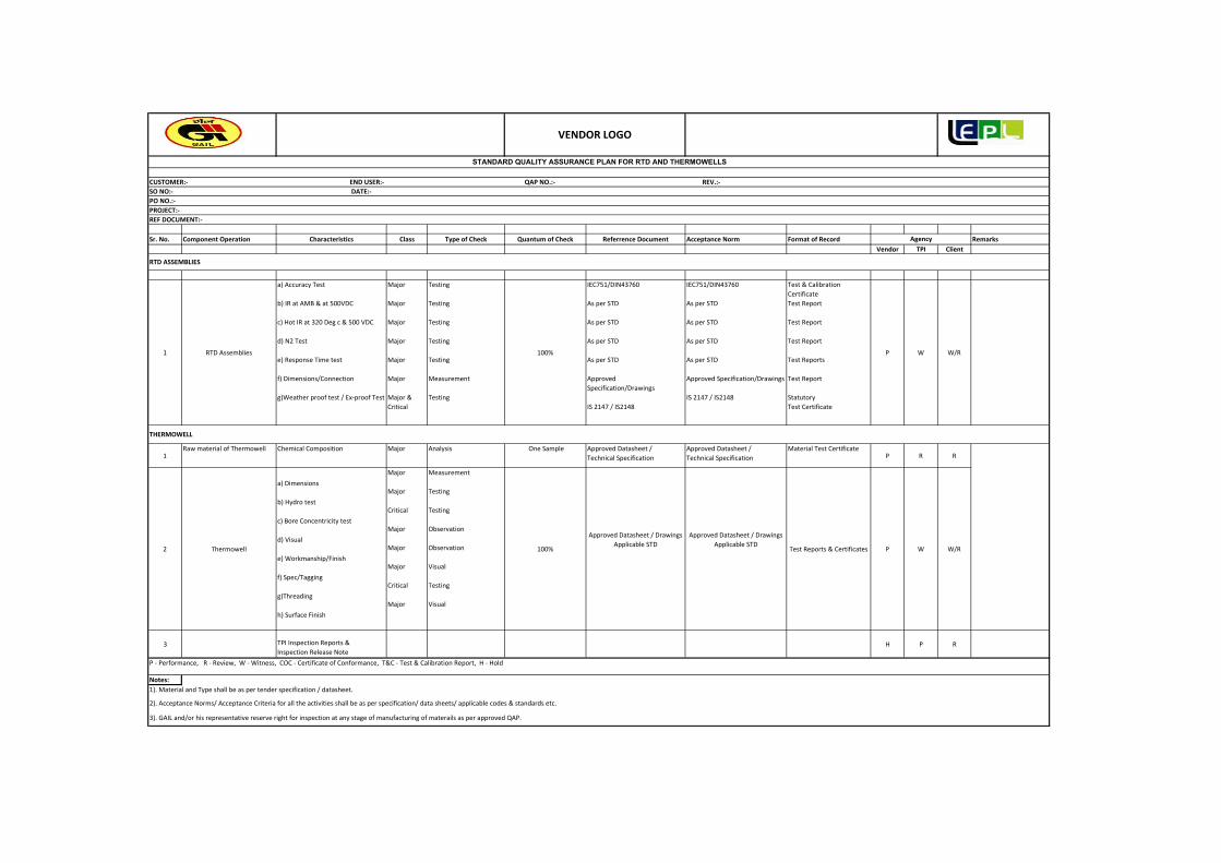
Sr. No. Component Operation Characteristics Class Type of Check Quantum of Check Referrence Document Acceptance Norm Format of Record Remarks
Vendor TPI Client
1 RTD Assemblies
a) Accuracy Test
b) IR at AMB & at 500VDC
c) Hot IR at 320 Deg c & 500 VDC
d) N2 Test
e) Response Time test
f) Dimensions/Connection
g)Weather proof test / Ex‐proof Test
Major
Major
Major
Major
Major
Major
Major &
Critical
Testing
Testing
Testing
Testing
Testing
Measurement
Testing
100%
IEC751/DIN43760
As per STD
As per STD
As per STD
As per STD
Approved
Specification/Drawings
IS 2147 / IS2148
IEC751/DIN43760
As per STD
As per STD
As per STD
As per STD
Approved Specification/Drawings
IS 2147 / IS2148
Test & Calibration
Certificate
Test Report
Test Report
Test Report
Test Reports
Test Report
Statutory
Test Certificate
P W W/R
1Raw material of Thermowell Chemical Composition Major Analysis One Sample Approved Datasheet /
Technical Specification
Approved Datasheet /
Technical Specification
Material Test CertificateP R R
2 Thermowell
a) Dimensions
b) Hydro test
c) Bore Concentricity test
d) Visual
e) Workmanship/Finish
f) Spec/Tagging
g)Threading
h) Surface Finish
Major
Major
Critical
Major
Major
Major
Critical
Major
Measurement
Testing
Testing
Observation
Observation
Visual
Testing
Visual
100%
Approved Datasheet / Drawings
Applicable STD
Approved Datasheet / Drawings
Applicable STDTest Reports & Certificates P W W/R
3 TPI Inspection Reports &
Inspection Release NoteH P R
P ‐ Performance, R ‐ Review, W ‐ Witness, COC ‐ Certificate of Conformance, T&C ‐ Test & Calibration Report, H ‐ Hold
Notes:
1). Material and Type shall be as per tender specification / datasheet.
2). Acceptance Norms/ Acceptance Criteria for all the activities shall be as per specification/ data sheets/ applicable codes & standards etc.
3). GAIL and/or his representative reserve right for inspection at any stage of manufacturing of materails as per approved QAP.
THERMOWELL
PO NO.:‐
PROJECT:‐
REF DOCUMENT:‐
Agency
RTD ASSEMBLIES
STANDARD QUALITY ASSURANCE PLAN FOR RTD AND THERMOWELLS
CUSTOMER:‐ END USER:‐ QAP NO.:‐ REV.:‐
SO NO:‐ DATE:‐
VENDOR LOGO

0
REV
GAIL‐STD‐IN‐DOC‐QAP‐003
Lyons Engineering Pvt. Ltd
15.01.2019 Issued for Bid RKS UNU UNU
Date Purpose of Issue Prepared By Checked By Approved By
GAIL INDIA LIMITED
QAP FOR PRESSURE TRANSMITTERS

Sr No. Component Operation Characteristics Class Type of Check Quantum of Check Reference document Acceptance norm Format of Record Remarks
Vendor TPI Client
1 Internal test/Inspection
Physical Verification
‐General Finish
‐Model no. & Serial no.
‐Tag no.
Certification
‐Accessories
‐Calibration
‐Range
‐Accuracy
‐Leak Check Process
Connection
‐‐Communication with
HART
Major
Critical
Visual
Electrical
100%
100%
Approved Datasheet /
Job Specification
Test and Calibration
ReportP R R
Physical Verification of
‐Model no., Serial no.,
Tag no.,
‐Process connection
check
‐Electrical/Conduit Entry
Connection check
‐Accessories check
Major
Visual 100%Approved Datasheet /
Job Specification
Approved Datasheet /
Job SpecificationCOC P W W / R
Calibration Critical Electrical 100%Approved Datasheet /
Job Specification
Approved Datasheet /
Job SpecificationT&C P W W / R
‐Accuracy
‐Repeatability
‐Indicator Operation
Check(if Meter display)
‐Communication with
Field Communicator
‐Power supply variation
test
‐Reverse Polarity Test
‐Load Variation Test
Critical Electrical 100%Approved Datasheet /
Job Specification
Approved Datasheet /
Job SpecificationCOC P W W / R
3 Review of Documents
‐Review of internal test
report & MTC
‐Hazardous Area
Classification Report
‐ Test & Calibration
Report
‐ Certification for
Compliance
‐ CCOE certificate
‐Degree of protection
certificate
MajorVisual 100%
Approved Datasheet /
Job Specification
Approved Datasheet /
Job Specification
Test Certificate &
COCP R R
4TPI Inspection Report &
Inspection Release NoteH P R
P ‐ Performance, R ‐ Review, W ‐ Witness, COC ‐ Certificate of Conformance, T&C ‐ Test & Calibration Report, H ‐ Hold
Notes: 1). Material and Type shall be as per tender specification / datasheet.
VENDOR LOGO
2
PO NO.:‐
PROJECT:‐
REF DOCUMENT:‐
Agency
STANDARAD QUALITY ASSURANCE PLAN FOR PRESSURE TRANSMITTER
2). Acceptance Norms/ Acceptance Criteria for all the activities shall be as per specification/ data sheets/ applicable codes & standards etc.
3).GAIL and/or his representative reserve right for inspection at any stage of manufacturing of materails as per approved QAP.
CUSTOMER:‐ END USER:‐ QAP NO.:‐ REV.:‐
SO NO:‐ DATE:‐
Final Test/ Inspection

GAIL‐STD‐IN‐DOC‐QAP‐004
0Rev.
GAIL INDIA LIMITED
QAP FOR PRESSURE GAUGES
Lyons Engineering Pvt. Ltd
15.01.2019 Issued for Bid RKS UNU UNUDate Purpose of Issue Prepared By Checked By Approved By
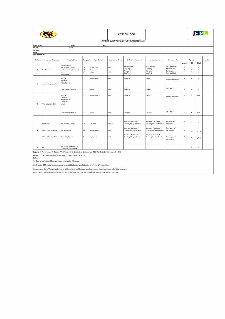
Sr. No. Component Operation Characteristics Category Type of Check Quantum of Check Reference Document Acceptance Norm Format of Plan Remarks
Vendor TPI Client
1 Raw Material
a) Dimensions
b) Chemical Analysis
c) Dial Marking, Unique, Srl.
No.
D) Dial Color
MA
MA
MA
Mechanical
Chemical
Visual
100%
Sample
100%
PO approved
Spec/Drg.
Approved
Spec/PO
PO approved
Spec/Drg.
Approved
Spec/PO
Test Certificate
Material Test
Certificate
Test Certificate
P
P
P
R
R
R
R
R
R
2 Internal Test/Inspection
Accuracy
Hystresis
Repeatability
Over range protection
CR
CR
Measurement
Visual
100%
100%
EN 837‐1
EN 837‐1
EN 837‐1
EN 837‐1
Calibration Report
Test Report
P
P
R
R
R
R
3 Final Test/Inspection
Accuracy
Hystresis
Repeatability
Dimension
Visual
Over range protection
CR
CR
Measurement
Visual
100%
100%
EN 837‐1
EN 837‐1
EN 837‐1
EN 837‐1
Calibration Report
Test Report
P
P
W
W
W/R
W/R
4
Accessories
Gauge Saver in SS 316
2‐Way Valve Manifold
1) Chemical Analysis
2) Dimensions
3) Leak Tightness
MA
MA
CR
Chemical
Measurement
Hydrotest
Sample
100%
100%
Approved Datasheet/
Drawing/Job Specification
Approved Datasheet/
Drawing/Job Specification
Approved Datasheet/
Drawing/Job Specification
Approved Datasheet/
Drawing/Job Specification
Approved Datasheet/
Drawing/Job Specification
Approved Datasheet/
Drawing/Job Specification
Material Test
Certificate
Test Reports/
Certificates
Test Reports/
Certificates
P
P
P
R
W
W
R
W / R
W/ R
3 IRNTPI Inspection Reports &
Inspection Release NoteP R
Legends: P ‐ Performance, R ‐ Review, W ‐ Witness, COC ‐ Certificate of Conformance, T&C ‐ Test & Calibration Report, H ‐ Hold
Category:
Notes:
1). Material and Type shall be as per tender specification / datasheet.
2). All Testing & Measuring Instruments shall have valid Calibration with Calibration Certificates & Traceabilities.
3). Acceptance Norms/ Acceptance Criteria for all the activities shall be as per specification/ data sheets/ applicable codes & standards etc.
4). GAIL and/or his representative reserve right for inspection at any stage of manufacturing of materails as per approved QAP.
SO NO:‐ DATE:‐
STANDARD QUALITY ASSURANCE PLAN FOR PRESSURE GUAGE
CUSTOMER:‐ QAP NO.:‐ REV.:‐
VENDOR LOGO
PO NO.:‐
PROJECT:‐
REF DOCUMENT:‐
Agency
CR ‐ Characteristics affecting safety of equipment and personnel

GAIL‐STD‐IN‐DOC‐QAP‐005
0
Rev.
GAIL INDIA LIMITED
QAP FOR TEMPERATURE GAUGES
Lyons Engineering Pvt. Ltd
15.01.2019 Issued for Bid RKS UNU UNU
Date Purpose of Issue Prepared By Checked By Approved By

Sr No. Components & Operation Characteristics Class Type of Check Quantum of Check Reference document Acceptance normVendor TPI Client
1 Raw Materials
1.1 Ring Chemical composition Major Chemical Analysis 100% As per Specification/data sheet Approved Documents P R R
1.2 Case Chemical composition Major Chemical Analysis 100% As per Specification/data sheet Approved Documents P R R
1.3 Movement Chemical composition Major Chemical Analysis 100% As per Specification/data sheet Approved Documents P R R
1.4 S.S. Socket Chemical composition Major Chemical Analysis 100% As per Specification/data sheet Approved Documents P R R
1.5 Dial Chemical composition Major Visual 100% As per Specification/data sheet Approved Documents P R R
1.6 Rubber Parts Oil Test Major Oil Test Sample As per Relevant Std Approved Documents P R R
2 Routine & Acceptance Testa
2.1 Thermometers Dimensions, Connections & Mounting Measurement, Visual 100% EN 13190 Std Approved Documents P R R
2.2 Calibration Test (5 points) Accuracy and Repeatability Calibration Check 100% Approved test procedure Approved Documents P R R
2.3 Response Time Test Response 10% Approved Documents P R R
3 In Process Inspection
3.1 Dimensional check Physical Measurement Major Measurement 100% As per Relevant Std Approved Drawings P R R
3.2 Leakage test Leak Test
Critical
Hydro test 100% As per Relevant Std As per Relevant Std P R R
4 Final Test Inspection
Performance check & Calibration P W W/R
a) Accuracy +/‐ 1% of FSD P W W/R
b) Repeatability P W W/R
c) Leakage P W W/R
4.2 Finished Gauge Protection Over Range Protection Major 130% of FSD 100% P W W/R
4.3 Casing Dimension, Enclosure Type Major Measurement 100% P W W/R
4.4 Finished GaugeIdentification, Name plate
detail,appearance & CleanlinessMinor Visual 100% P W W/R
5 Review of Documents Weather Proof TestMajor
Environmental Type test report IS 2147 / IEC 60529 As per Relevant Std P R R
1 Raw material of Thermowell Chemical Composition Major Analysis One SampleApproved Datasheet /
Technical Specification
Approved Datasheet /
Technical SpecificationP R R
THERMOWELL
QUALITY ASSURANCE PLAN FOR TEMPERATURE GAUGE WITH THERMOWELL
Agency
Major Measurement 100%
As per Relevant StdApproved Documents /
Relevant Std
VENDOR LOGO
4.1 Finish Product check for completeness

2 Thermowell
a) Dimensions
b) Hydro test
c) Bore Concentricity test
d) Visual
e) Workmanship/Finish
f) Spec/Tagging
g)Threading
h) Surface Finish
Major
Major
Critical
Major
Major
Major
Critical
Major
Measurement
Testing
Testing
Observation
Observation
Visual
Testing
Visual
100%
Approved Datasheet / Drawings
Applicable STD
Approved Datasheet / Drawings
Applicable STDP W W/R
3TPI Inspection Reports &
Inspection Release NoteH P R
4). GAIL and/or his representative reserve right for inspection at any stage of manufacturing of materails as per approved QAP.
Notes:
LEGEND: R: Review, W: Witness, P: Perform, H: Hold
1). Material and Type shall be as per tender specification / datasheet.
2). All Testing & Measuring Instruments shall have valid Calibration with Calibration Certificates & Traceabilities.
3). Acceptance Norms/ Acceptance Criteria for all the activities shall be as per specification/ data sheets/ applicable codes & standards etc.

QAP FOR INSTRUMENT CABLES
GAIL‐STD‐IN‐DOC‐QAP‐006
0Rev.
GAIL INDIA LIMITED
Approved By Lyons Engineering Pvt. Ltd15.01.2019 Issued for Bid RKS UNU UNU
Date Purpose of Issue Prepared By Checked By

1.2
Insulation &
Sheathing
compound
1. Tensile & Elongation before
& after ageingA Visual P R R
2. Type of compound C Visual P R R
3. Thermal Stability C Physical P R R
FR Test for FR PVC
only1. Oxygen Index C Enviro Min. 30% P R R
2. Temperature Index C Enviro Min 250deg C P R R
1.3 Armour 1. Surface Condition A Visual P R R
2. Uniformity of Zinc Coating C Chemical P R R
3. Mass of zinc coating B Chemical P R R
4. Tensile strength &
elongationB Physical P R R
5. Wrapping B Physical P R R
6. Torsion/ Winding B Physical P R R
2 Process Inspection
2.0 Insulated core 1. Type of Material B Visual P R R
2. Thickness of Insulation
(Avg. Min.)C Physical P R R
CUSTOMER:‐ QAP NO.:‐ REV.:‐
SO NO:‐ DATE:‐
PO NO.:‐
PROJECT:‐
BS 5308(P‐2) &
One sample per
batch
IS 3975/ BS 5308(P‐2)
Relevant Standard as per
Specification
IS 3975/ BS 5308(P‐2)
Relevant Standard as
per Specification
Each setting & BS 5308(P‐2) & Relevant
One sample per
batch
IS 5831/ BS 5308(P‐
2)Relevant Standard as
per Specification
IS 5831/ BS 5308(P‐
2)Relevant Standard
as per Specification
ASTM‐D2863
VENDOR LOGO
REF DOCUMENT:‐
QAP for Instrument Cables

3. Core Identification C Visual P R R
4. Surface Finish B Visual P R R
5. Volume Resistivity C Electrical P R R
2.1 Pair/Triad 1. Sequence of laying C Visual P R R
2. Continuity of conductor C Electrical P R R
3. Lay Length B Physical P R R
2.2 Pair/Triad screeing 1. Tape thickness B Physical P R R
2. Tape overlap B Visual P R R
3. Drain wire size B Physical P R R
2.3 Pair/Triad Laying 1. Sequence of laying B Visual P R R
2. Lay Length B Physical P R R
3. Dimension B Physical P R R
4. Continuity of conductor C Electrical P R R
5. HV C Electrical P R R
6. Continuity of common pair C Electrical P R R
2.4 Overall screeing 1. Tape thickness B Physical P R R
2. Tape overlap B Visual P R R
3. Drain wire size B Physical P R R
2.5 Inner sheath 1. Type of PVC B Visual P R R
2. Dimension B Physical P R R
3. Thickness of Inner Sheath C Physical P R R
4. Surface finish & Colour B Visual
BS 5308(P‐2)/Should
be smooth & free
from porosity &
Relevant Standard as
per Specification
P R R
Setting & During
Process
BS 5308(P‐2) & Relevant
Standard as per
Specification
BS 5308(P‐2) &
Relevant Standard as
per Specification
Each setting & at
the running of
M/c
BS 5308(P‐2) & Relevant
Standard as per
Specification
BS 5308(P‐2) &
Relevant Standard as
per Specification
Setting & During
Process
BS 5308(P‐2) & Relevant
Standard as per
Specification
BS 5308(P‐2) &
Relevant Standard as
per Specification
Setting & During
Process
BS 5308(P‐2) & Relevant
Standard as per
Specification
BS 5308(P‐2) &
Relevant Standard as
per Specification
100% Drum
( )
Relevant Standard as
per Specification
Setting & During
Process
BS 5308(P‐2) & Relevant
Standard as per
Specification
BS 5308(P‐2) &
Relevant Standard as
per Specification
g
during run of
M/c
( )
Standard as per
Specification

2.6 Armouring 1. No. of strips/wires B Visual P R R
2. Dimension of strips/wires B Physical P R R
3. Direction of lay B Visual P R R
2.5 Conductor 1. Make up B Visual P R R
2. Size/Dimensions B Physical P R R
3. DC Resistance at 20deg C C Electrical P R R
2.6 Outer Sheath 1. Type of PVC Compound C Physical P R R
2. Thickness
Average/MinimumC Physical P R R
3. Dia over Outer sheath B Physical P R R
4. Colour B Visual P R R
5. Surface finish B Visual P R R
6. Embossing/
Printing/Sequential MarkingB Visual P R R
3 Routine Test P
1. Conductor Resistance B Electrical 100% Drums
IS 8130/ BS 5308(P‐2) &
Relevant Standard as per
Specification
IS 8130/ BS 5308(P‐2)
& Relevant Standard
as per Specification
P R R
2. Mutual Capacitance B Electrical 10% Drums P R R
3. Capacitance between core
& screenB Electrical 10% Drums P R R
4. L/R Ratio B Electrical 10% Drums P R R
5. HV Test a) Core
to core b) Core to
shield/Armour
C Electrical 100% Drums P R R
6. Spark Test
a. Core
b. Sheath
BS 5308(P‐2) / BS 5099
& Relevant Standard as
per Specification
Relevant Standard as
per SpecificationP R R
7. Test for rodent & termite
repulsionP R R
4 Final Test
Setting & During
running of M/c
BS 5308(P‐2) & Relevant
Standard as per
Specification
BS 5308(P‐2) &
Relevant Standard as
per Specification
BS 5308(P‐2) & Relevant
Standard as per
Specification
BS 5308(P‐2) &
Relevant Standard as
per Specification
Starting of M/c &
during process
BS 5308(P‐2) & Relevant
Standard as per
Specification
BS 5308(P‐2) &
Relevant Standard as
per Specification
100% spools at
start & end
IS 8130/ BS 5308(P‐2) &
Relevant Standard as per
Specification
IS 8130/ BS 5308(P‐2)
Relevant Standard as
per Specification

1. HV Test a) Core
to core b) Core to
shield/Armour
C Electrical 10% Sample
BS 5308(P‐2) & Relevant
Standard as per
Specification
BS 5308(P‐2) &
Relevant Standard as
per Specification
P W W/R
2. Conductor Resistance B Electrical 10% Sample
IS 8130/ BS 5308(P‐2) &
Relevant Standard as per
Specification
IS 8130/ BS 5308(P‐2)
& Relevant Standard
as per Specification
P W W/R
3. Continuity test B Electrical 10% Sample P W W/R
4. Insulation Resistance
(Before & After HV)
a. Individual Conductor
b. Individual Screens
C ElectricalOne sample per
lotP W W/R
5. Tensile Strength &
Elongation for Insulation &
sheath before ageing
B Physical 10% Sample P W W/R
6. Dimension B Visual 10% Sample P W W/R
7. Electrostatic noise
reduction ratioB Electrical
One sample per
lotP W W/R
8. Cable capacitance & L/R
ratio testB Electrical 10% Sample P W W/R
9. Spark Test
a. Core
b. Sheath
BS 5308(P‐2) / BS 5099
& Relevant Standard as
per Specification
Relevant Standard as
per SpecificationP W W/R
Flammability Test
for FRLS PVC only1. Oxygen Index C Enviro Min. 30% P W W/R
2. Temperature Index C Enviro Min 250deg C P W W/R
3. Flammability test C Fire IEC 332‐1 Shall Pass P W W/R
4. Smoke Density As
Applicable
As
ApplicableASTM 2843 P W W/R
5. Acid Gas GenerationAs
Applicable
As
ApplicableIEC‐754‐1 P W W/R
6. Swedish Chimmney TestAs
Applicable
As
Applicable
As per Relevant
StaandardP W W/R
One sample per
lot
ASTM‐D2863
BS 5308(P‐2) & Relevant
Standard as per
Specification
BS 5308(P‐2) &
Relevant Standard as
per Specification

5 Type Test
5.0Tests For
Conductor1. Conductor Resistance B Electrical
One sample per
lot
IS 8130/ BS 5308(P‐2) &
Relevant Standard as per
Specification
IS 8130/ BS 5308(P‐2)
& Relevant Standard
as per Specification
P R R
2. Annealing Test on Cu Physical
BS 6360 & Relevant
Standard as per
Specification
BS 6360 & Relevant
Standard as per
Specification
P R R
5.1Test on Armour
wire/strip1. Tensile strength B Physical P R R
2. % Elongation B Physical P R R
3. Torsion/Winding B Physical P R R
4. Wt. of zinc coating B Chemical P R R
5. Dimensions B Physical P R R
6. Uniformity of coating C Chemical P R R
5.2
Thickness of
Insulation &
Sheath
Thickness of Insulation &
SheathB Physical
One sample per
lot
BS 5308(P‐2) & Relevant
Standard as per
Specification
BS 5308(P‐2) &
Relevant Standard as
per Specification
P R R
5.3
Physical tests on
Insulation & Outer
Sheath
1. Elongation & T. S. Before &
After AgeingB Physical P R R
2. Ageing in Air oven B Physical P R R
3. Shrinkage test B Physical P R R
4. Hot Deformation B Physical P R R
5. Heat Shock B Physical P R R
6. Thermal stability B Physical P R R
7. Flammability Test B Physical P R R
8. Loss of Mass B Physical P R R
5.4
Insulation
Resistance test at
room & rated
temperature
Volume resistivity C ElectricalOne sample per
lot
BS 5308(P‐2) & Relevant
Standard as per
Specification
BS 5308(P‐2) &
Relevant Standard as
per Specification
P R R
5.5H.V. test at room
temperatureH.V. test at room temperature B Electrical
One sample per
lot
BS 5308(P‐2) & Relevant
Standard as per
Specification
BS 5308(P‐2) &
Relevant Standard as
per Specification
P R R
BS 5308(P‐2) &
Relevant Standard as
per Specification
One sample per
lot
One sample per
lot
BS 5308(P‐2) & Relevant
Standard as per
Specification
BS 5308(P‐2) & Relevant
Standard as per
Specification
BS 5308(P‐2) &
Relevant Standard as
per Specification

5.7 Flammability test FRLS Tests (FR PVC Only)Relevant Standard as per
Specification
Relevant Standard as
per SpecificationP R R
1. Oxygen Index ASTM 2863 Min. 30% P R R
2. Temperature Index ASTM 2863 Min 250deg C P R R
4. Smoke Density ASTM 2843 ASTM 2843 P R R
5. Acid Gas Generation IEC‐754‐1 IEC‐754‐1 P R R
6. Swedish Chimmney TestAs per Relevant
Staandard
As per Relevant
StaandardP R R
LEGENDS:
Notes:
1). All Testing and Measuring Equipments / Instruments shall have valid Calibration with Calibration Certificate & their Traceabilities.
3). GAIL and/or his representative reserve right for inspection at any stage of manufacturing of materails as per approved QAP.
4). All Testing & Measuring Instruments shall have valid Calibration with Calibration Certificates & Traceabilities.
2). Acceptance Norms/ Acceptance Criteria for all the activities shall be as per specification/ data sheets/ applicable codes & standards etc.
C EnviroOne sample per
lot
R: Review of Docs., A: Minor, B: Major, C: Critical, W: Witness

QAP FOR PRESSURE SAFETY VALVESGAIL‐STD‐IN‐DOC‐QAP‐007
0REV
GAIL INDIA LIMITED
Approved By Lyons Engineering Pvt. Ltd15.01.2019 Issued for Bid RKS UNU UNU
Date Purpose of Issue Prepared By Checked By

Sr No. Components & Operation Characteristics Class Type of Check Quantum of Check Reference document Acceptance norm
Vendor TPI Client
1 Raw Materials
1.1
Incoming materials like
Forgings and castings for
body, Bonnet & Nozzle,
Springs, Bellows etc.
i. Material
Properties
(Mechanical &
Chemical )
ii. Size
iii. Rating
iv. Make
v. Type
Major Visual 100%
As per clause 3.1 of EN
10204 for each valve body
& Bonnet/forging, nozzle
and clause 2.2 for stem,
disc etc.
Manufacturers
certificate of
conformity
P R R
1.2Machining of components
& their assembly.Dimensions, Finish Major Visual/Physical 100%
Data sheet/Standard
specification/Relevant
code
Data sheet/Standard
specification/Relevan
t code
P R R
i. Radiography of
valve castingsMajor Visual/Physical 100% ANSI B16.34 ANSI B16.34 annex.B P R R
ii. Bend test &
Magnetic Particle
Inspection of Body
& Bonnet casting
Major Visual/Physical 100% P R R
iii. Charpy V ‐notch
impact testing (If
specified)
Major Visual/Physical 100% P R R
iv. Visual check,
Verification of tag
plate/Marking,
Accessories.
Major visual 100% P R R
v. Helium Leak test Major Physical 100% P R R
vi. Dye Penetrant
test of Welds.Major Physical 100% P R R
vii. Hydrostatic
test.Major Physical 100% P R R
viii. Cold bench set
pressureMajor Physical 100% P R R
ix. Seat Leakage
testMajor Physical 100% API RP 527 API RP 527 P R R
x. Valve lift test. Major Visual/Physical 100% P R R
xi. Blow down/
Reclosing pressure
test
Major Physical 100% P R R
xii. Capacity test Major Physical 100% P R R
xiii. Post weld Heat
treatment of weld
joints
Major Physical 100% P R R
i. Dimensional,
Finish, Visual
check, Verification
of tag
plate/Marking,
Accessories.
Major
Visual/Physical P W W/R
ii. Helium Leak test Critical Physical P W W/R
iii. Dye Penetrant
test of Welds.Major Physical P W W/R
iv. Hydrostatic test. Major Physical P W W/R
v. Cold bench set
pressureMajor Physical P W W/R
vi. Seat Leakage
testMajor Physical API RP 527 API RP 527 P W W/R
vii. Valve lift test. Major Visual/Physical
Data sheet/Standard
specification/Relevant
code
Data sheet/Standard
specification/Relevan
t code
P W W/R
i. Review of IBR
certificate & Type
test report for
valves under IBR
regulation (If
Applicable)
Critical Visual 100%
Data sheet/Standard
specification/Relevant
code
Data sheet/Standard
specification/Relevan
t code
P R R
ii. PWHT report/
Radiography
reports/MPI
reports
Critical Visual 100%
Data sheet/Standard
specification/Relevant
code
Data sheet/Standard
specification/Relevan
t code
P R R
VEDOR LOGO
Data sheet/Standard
specification/Relevant
code
Data sheet/Standard
specification/Relevan
t code
Internal test/Inspection
Agency
QUALITY ASSURANCE PLAN FOR PRESSURE SAFETY VALVE
4 Review of Documents
Data sheet/Standard
specification/Relevant
code
Data sheet/Standard
specification/Relevan
t code
3 Final Inspection Test 100%
Data sheet/Standard
specification/Relevant
code
Data sheet/Standard
specification/Relevan
t code
1.3

iii. Capacity test as
per ASME (Type
test report)
Critical Visual 100%
Data sheet/Standard
specification/Relevant
code
Data sheet/Standard
specification/Relevan
t code
P R R
iv. Material test
certificate Major Visual 100%
As per clause 3.1 of EN
10204 for each valve body
& Bonnet/forging, nozzle
and clause 2.2 for stem,
disc etc.
Data sheet/Standard
specification/Relevan
t code
P R R
LEGENDS: R: Review of Docs W: Witness
Notes:
2). GAIL and/or his representative reserve right for inspection at any stage of manufacturing of materails as per approved QAP.
3). All Testing & Measuring Instruments shall have valid Calibration with Calibration Certificates & Traceabilities.
P: Perform
1). Acceptance Norms/ Acceptance Criteria for all the activities shall be as per specification/ data sheets/ applicable codes & standards etc.

QAP FOR PIG SIGNALLER
GAIL‐STD‐IN‐DOC‐QAP‐008
0
REV
GAIL INDIA LIMITED
Approved By Lyons Engineering Pvt. Ltd
15.01.2019 Issued for Bid RKS UNU UNU
Date Purpose of Issue Prepared By Checked By
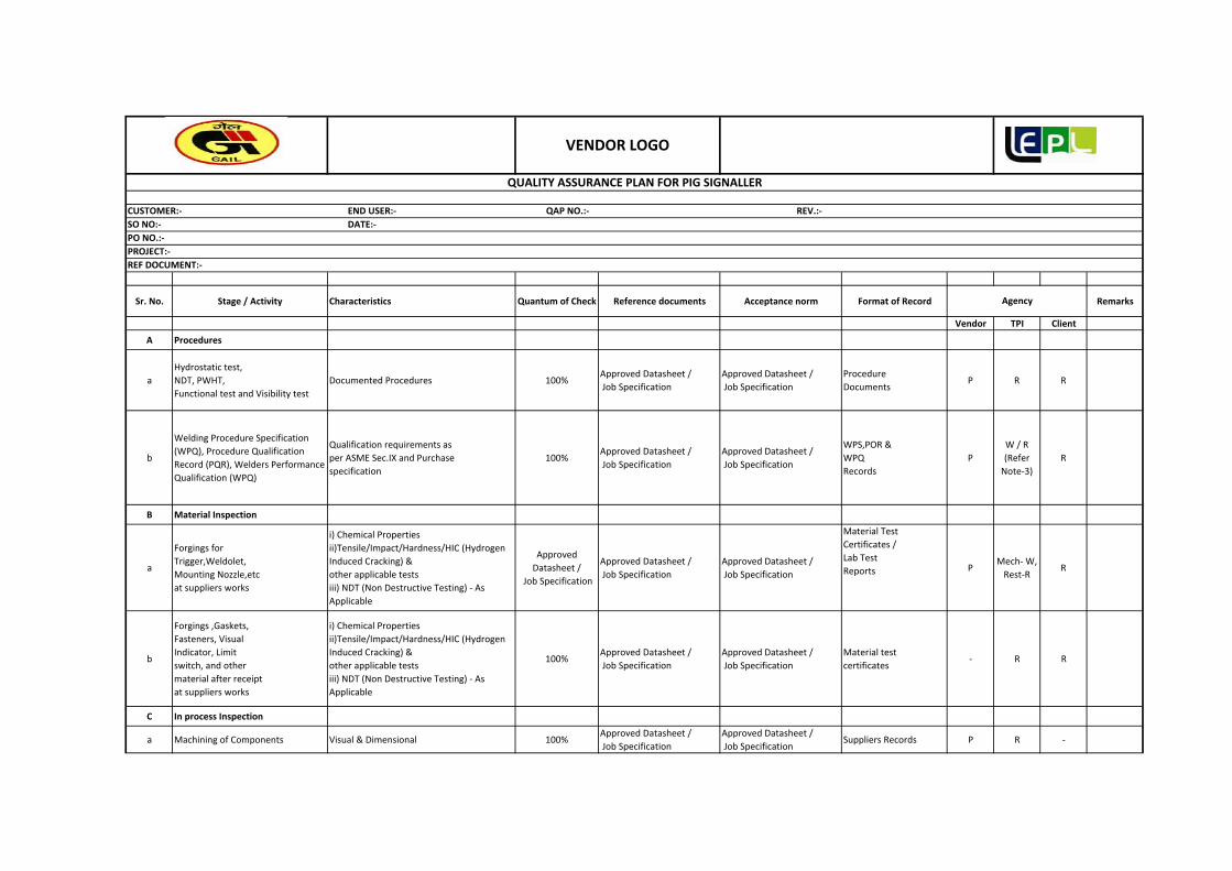
Sr. No. Stage / Activity Characteristics Quantum of Check Reference documents Acceptance norm Format of Record Remarks
Vendor TPI Client
A Procedures
a
Hydrostatic test,
NDT, PWHT,
Functional test and Visibility test
Documented Procedures 100%Approved Datasheet /
Job Specification
Approved Datasheet /
Job Specification
Procedure
DocumentsP R R
b
Welding Procedure Specification
(WPQ), Procedure Qualification
Record (PQR), Welders Performance
Qualification (WPQ)
Qualification requirements as
per ASME Sec.IX and Purchase
specification
100%Approved Datasheet /
Job Specification
Approved Datasheet /
Job Specification
WPS,POR &
WPQ
Records
P
W / R
(Refer
Note‐3)
R
B Material Inspection
a
Forgings for
Trigger,Weldolet,
Mounting Nozzle,etc
at suppliers works
i) Chemical Properties
ii)Tensile/Impact/Hardness/HIC (Hydrogen
Induced Cracking) &
other applicable tests
iii) NDT (Non Destructive Testing) ‐ As
Applicable
Approved
Datasheet /
Job Specification
Approved Datasheet /
Job Specification
Approved Datasheet /
Job Specification
Material Test
Certificates /
Lab Test
Reports PMech‐ W,
Rest‐RR
b
Forgings ,Gaskets,
Fasteners, Visual
Indicator, Limit
switch, and other
material after receipt
at suppliers works
i) Chemical Properties
ii)Tensile/Impact/Hardness/HIC (Hydrogen
Induced Cracking) &
other applicable tests
iii) NDT (Non Destructive Testing) ‐ As
Applicable
100%Approved Datasheet /
Job Specification
Approved Datasheet /
Job Specification
Material test
certificates‐ R R
C In process Inspection
a Machining of Components Visual & Dimensional 100%Approved Datasheet /
Job Specification
Approved Datasheet /
Job SpecificationSuppliers Records P R ‐
PO NO.:‐
PROJECT:‐
REF DOCUMENT:‐
Agency
QUALITY ASSURANCE PLAN FOR PIG SIGNALLER
CUSTOMER:‐ END USER:‐ QAP NO.:‐ REV.:‐
SO NO:‐ DATE:‐
VENDOR LOGO

b Inspection of Weldsi) Visual
ii) Applicable NDT100%
Approved Datasheet /
Job Specification
Approved Datasheet /
Job SpecificationTest Reports P
W/R
(Refer
Note‐1)
R
c Heat Treatment Heat treatment as applicable 100%Approved Datasheet /
Job Specification
Approved Datasheet /
Job SpecificationHT Chart/Record P R
D Final Inspection
a Functional Test Satisfactory Performance 100%Approved Datasheet /
Job Specification
Approved Datasheet /
Job SpecificationTest Reports P W W/R
b Hydrostatic Test Leak Check 100%Approved Datasheet /
Job Specification
Approved Datasheet /
Job SpecificationTest Reports P W W/R
c Visual and Dimensional InspectionDimensions & Completeness of
Assembly100%
Approved Datasheet /
Job Specification
Approved Datasheet /
Job Specification
Inspection
RecordP W W/R
E Painting
a
Corrosion Resistant
Painting & / or Antifouling Coating
(As Applicable)
i) Painting Scheme
ii) Visual Check
iii) Final DFT Check
100%Approved Datasheet /
Job Specification
Approved Datasheet /
Job Specification
Inspection
RecordP R R
F Documentation and IC
aFinal Documentation
& Inspection Certificate(IC)
Issue of IC & Final document
completeness certificateAs per PR
Approved Datasheet /
Job Specification
Approved Datasheet /
Job Specification
IC & Document
completeness
certificate
H P R
Legend:
H‐ Hold (Do not proceed without approval), Random ‐10% (min. 1 no.) of each size and type of Bulk item, R‐Review, W‐Witness (Give due notice, work may proceed after scheduled date).
Notes:
1). Inspection Engineer shall decide the option to be exercised for the particular stage and Suppliers
2). Forgings for Trigger, Weldolet, Mounting Nozzle, etc Shall be procured duly inspected by TPIA appointed by Supplier.
3). Witness‐If New PQR / Applicable PQR is not qualified under reputed TPIA. Review‐If Applicable PQR is qualified under reputed TPIA.
4) Supplier’s in house procedures may be accepted in case TPIA is satisfied with adequacy of procedures to comply with Purchase Order/Specifications requirements; in case of non availability of suitable procedure s fresh
procedures may be qualified under EIL witness.
5). In case of conflict between purchase specification, contract documents and QAP more stringent conditions shall be applicable.
6). This document describes generally the requirements pertaining to all types of the item. Requirements specific to PO and the item are only applicable.
7). Acceptance Norms/ Acceptance Criteria for all the activities shall be as per relevant/ job specification / Standard specifica tion/ data sheets/applicable codes & Standards etc. referred there in /Job Specification /Approved
Documents.

QAP FOR GAS DETECTOR
GAIL‐STD‐IN‐DOC‐QAP‐009
0REV
GAIL INDIA LIMITED
Approved By Lyons Engineering Pvt. Ltd15.01.2019 Issued for Bid RKS UNU UNU
Date Purpose of Issue Prepared By Checked By

Sr No.Components &
OperationCharacteristics Class Type of Check Quantum of Check Reference document Acceptance norm
Vendor TPI GSPL
1 Raw Materials
1.1Gas detectors, Portable gas detectors & Power supply units,
i. Material Properties ii. Size iii. Rating iv. Make v. Type/Model No.
Major Visual 100%Clause 2.2 of DIN 50049/BS EN-
50054 & 50057Manufacturers certificate of
conformityP R R
2 In Process Inspection
2.2 Internal test/Inspection i. Calibration check of gas detectors including alarm. ii. General Finish &Physical Verification of-Model no. - Range - Serial no.-Tag no.- Certification label- Accessories iii. Bill of material check iv. Interface with RTUv. Checking of all power wiring for continuity. vi. Checking of all control wiring for continuity & Polarity
Critical
Major
Major
Electrical/Physical
Visual
VisualPhysical / Electrical Electrical/Physical Physical Physical
100%BS EN-50054/BS EN-
50057/Relevant DrawingBS EN-50054/BS EN-
50057P R R
i. Calibration check of gas dtectors including alarm. Critical Electrical/Physical P W W/R
ii. Interface with SCADA/RTU Critical Physical P W W/R
i. Statuary approval certificates (BIS or equivalent) for gas detectors, portable detectors etc. for use in specified Hazardous area.
Critical Visual 100% IS-2148/IEC-79 IS-2148/IEC-79 P R R
ii. Certificates from testing agencies like BASEEFA, CENELEC, CMRI, FM, PTB, CCOE/PESO or equivalent for gas detectors, portable detectors, Junction boxes etc. for use in specified Hazardous area.
Critical Visual 100% IS-2148/IEC-79 IS-2148/IEC-79 P R R
iii. Degree of Protection Critical Visual 100% IS-2147/IEC-529 IS-2147/IEC-530 P R R
iv. Material test certificate with detailed chemical analysis (MIL certificate)
Critical Visual 100%Clause 2.2 of DIN 50049/BS EN-
50054 & 50057
Clause 2.2 of DIN 50049/BS EN-50054 &
50057P R R
LEGENDS: R: Review of Docs, W: Witness, P: Perform
Notes:
1). Acceptance Norms/ Acceptance Criteria for all the activities shall be as per relevant specification/ data sheets/ applicable codes & standards etc. referred there in /Job Specification /Approved Documents.
PO NO.:‐
PROJECT:‐
3
Agency
REF DOCUMENT:‐
Witness Test Inspection
4 Review of Documents
QUALITY ASSURANCE PLAN FOR GAS DETECTOR
VENDOR LOGO
CUSTOMER:‐ END USER:‐ QAP NO.:‐ REV.:‐
SO NO:‐ DATE:‐
GAS OVER OIL ACTUATOR
GAIL‐STD‐IN‐DOC‐QAP‐010
0REV
GAIL INDIA LIMITED
Approved By Lyons Engineering Pvt. Ltd15.01.2019 Issued for Bid RKS UNU UNU
Date Purpose of Issue Prepared By Checked By

Remarks
Sub Suppliar suppliar
1 Procedures -- -- -- -- --
2 Material Description
2.1
Incoming material like Control Valves, Solenoid Valves,Gaskets,Junction Boxes, Flow regulators, Hydraulic filters, Gas Filters, Limit Switches, Instrument tubing,Cables,Hydraulic
Pumps,Limit Valves, Pressure Gauges, etc.
1. Matreial Identification & Chemical Composition2. Mechanical & Physical propserties3. Operational Checks4. Caliberation Checks (As applicable)
100% by Supplier
Refer note -6 Refer note -5Material test Certificate
p H
2.2 Oil TanksHydrostatic Pressure test 100% by Sub
SupplierRefer note -6 Refer note -5
Material test Certificate
p H
2.3 Gas Buffer Tanks Hydrostatic Pressure test 100% by Sub Supplier
Material test Certificate
p H
2.4 Hydraulic Fluid 1.Chemical Composition2. Cleanliness Levels
100% by Sub Supplier
Refer note -6 Refer note -5Material test Certificate
p H
3 In Process Inspection
3.1 Castings of pressure Contating Parts Radiographt test 100% by Supplier
Refer note -6 Refer note -5Supplier's test
record- H
3.2 Forgings Ultrasonic testing 100% by Supplier
Refer note -6 Refer note -5Supplier's test
record- H
3.3 Machined Surface Liguid Penetrent test 100% by Supplier
Refer note -6 Refer note -5Supplier's test
record- H
Sealing areas within the actuator body Magnetic particle Testing 100% by Supplier
Refer note -6 Refer note -5Supplier's test
record- H
Actuator body Pressure test for Flame proff Enclosuere
100% by Supplier
Refer note -6 Refer note -5Supplier's test
record- H
Complete Assembly 1. Visual, Dimensional & BOM2.Operation Checks
100% by Supplier
Refer note -6 Refer note -5Supplier's test
record- H
4 Final Inspection
Reference DocumentCharacterstics
Inspection ByQuantum of
CheckFormat Of
RecordsSr. No.
QUALITYASSURANCEPLANGASOVEROILACTUATOR
Stage /Activity
DOC.No.GAIL‐STD‐IN‐DOC‐QAP‐010
Acceptance Norms
Page 2 of 4

Remarks
Sub Suppliar suppliarReference DocumentCharacterstics
Inspection ByQuantum of
CheckFormat Of
RecordsSr. No.
QUALITYASSURANCEPLANGASOVEROILACTUATOR
Stage /Activity
DOC.No.GAIL‐STD‐IN‐DOC‐QAP‐010
Acceptance Norms
4.1
Final Inspection ( At Actuator Manufacturer's Works)
1. Visual, Dimensional Checks2. Bill of Material2.Verification of Tag no. and Plate no.4.Hydrostatics test at 1.5 times the actuator Design pressure for min. 2 hrs.5.Check for Actuator torque or Thrust6. Seal test of Hydraulic Circuits7. Verification of opening and closing time and contriol of operating time8. Actutaor functional test including open close operations ( at Least 5 times) Remote operation of actuatorand checking of all remote feedbacks and signals, Local operation of actuator, operation of linit switches and position indicators (mechanical & Electrical)9. Check for Emergency manual override.
100% by Supplier and on random
basis by EIL/TPIA
Refer note -6 Refer note -5Supplier's test
record- P
4.2 Integral Testing Valve/Actuator assembly test at valve manufacturer's work.The following as a minmum shall be Carried out- Open/Close Operations. ( at min. & Max. Pressure.-Stroke time ( if applicable)-No Load test or Load operations with the min. Required feeding pressure.- Electrical and Mechanical Operation test.
100% of each type and rating
Refer note -6 Refer note -5Supplier's test
record- P
5 Painting
Page 3 of 4

Remarks
Sub Suppliar suppliarReference DocumentCharacterstics
Inspection ByQuantum of
CheckFormat Of
RecordsSr. No.
QUALITYASSURANCEPLANGASOVEROILACTUATOR
Stage /Activity
DOC.No.GAIL‐STD‐IN‐DOC‐QAP‐010
Acceptance Norms
5.1 Painting & Packing 1. Visual2. Suitable protection to prevent entry of foreign material3. Protection against damage during transportation4. Suitable packing for outdoor storage areas with heavy rains/high ambient temprature ubnless otherwise agreed
100% Refer note -6 Refer note -5Supplier's test
record- W
6 Documentation and IC
6.1 Documentation and IC
1. Certificate for testing agency like ATEX,CIMFR,BASEEFA,FM/UL, PTB etc. for suitablity in specified hazardeous area.2. Statutory approval certificates from CCE/PESO for use in specifiesd hazardeous area.3. Degree of protection certificate for actutaor enclosure, JB, Solenoid Enclosure, Limit switches etc.4. Flameproof Certification for cable glands, Relays, Valves etc from independent testing agency.4. A valid BIS license for inmdegenious supply.5. Operation and maintenace manual
100% Refer note -6 Refer note -5Supplier's test
record- R
M : Manufacturer C : Client (GAIL) A : Approval H : Hold R : ReviewNA : Not Applicable W / R : Witness of Test & Review of Certificates & Documents as per QAP W : Witness RW : Random Witness
Notes: -1
2
3
4
5 Reference documents are relevent Job specifications /standard specifications/data sheets/applicable codes & standards
Legend :
wherever W/R or H/W is indicated, inspection Engineer shall decide the option to be exercised for the particular stage and supplier.
- Supplier to submit internal test reports, type test reports before offereing items for ispection to TPIA.*Radiography Films shall be reviewed
In case of conflict between purchase specification, cotract documents and ITP, more stringent conditions shall be applicable.
This documnets describes genreally the requirements pertaining to all types of the items. Requirements specific to PO and the item are only applicable
Acceptance norms/ acceptance criteria for all the activities shall be as per relevent/job specification/standard specification/data sheets/applicable codes & standard etc. refered there in /job specification/approved documents.
Page 4 of 4

LYONS ENGINEERING PVT. LTD.
NEW DELHI

LYONS ENGINEERING PVT. LTD.
NEW DELHI

LYONS ENGINEERING PVT. LTD.
NEW DELHI

LYONS ENGINEERING PVT. LTD.
NEW DELHI

LYONS ENGINEERING PVT. LTD.
NEW DELHI

LYONS ENGINEERING PVT. LTD.
NEW DELHI

LYONS ENGINEERING PVT. LTD.
NEW DELHI

LYONS ENGINEERING PVT. LTD.
NEW DELHI

LYONS ENGINEERING PVT. LTD.
NEW DELHI
FLOW METER
INSTALLATION
SCOPE OF WORK

LYONS ENGINEERING PVT. LTD.
NEW DELHI
FLOW METER
INSTALLATION
SCOPE OF WORK

LYONS ENGINEERING PVT. LTD.
NEW DELHI
FLOW METER
INSTALLATION
SCOPE OF WORK

LYONS ENGINEERING PVT. LTD.
NEW DELHI
FLOW METER
INSTALLATION
SCOPE OF WORK

LYONS ENGINEERING PVT. LTD.
NEW DELHI
FLOW METER
INSTALLATION
SCOPE OF WORK

LYONS ENGINEERING PVT. LTD.
NEW DELHI
FLOW METER
INSTALLATION
SCOPE OF WORK

LYONS ENGINEERING PVT. LTD.
NEW DELHI
FLOW METER
INSTALLATION
SCOPE OF WORK

LYONS ENGINEERING PVT. LTD.
NEW DELHI
FLOW METER
INSTALLATION
SCOPE OF WORK

LYONS ENGINEERING PVT. LTD.
NEW DELHI

LYONS ENGINEERING PVT. LTD.
NEW DELHI

LYONS ENGINEERING PVT. LTD.
NEW DELHI

LYONS ENGINEERING PVT. LTD.
NEW DELHI

LYONS ENGINEERING PVT. LTD.
NEW DELHI

LYONS ENGINEERING PVT. LTD.
NEW DELHI

LYONS ENGINEERING PVT. LTD.
NEW DELHI

LYONS ENGINEERING PVT. LTD.
NEW DELHI

LYONS ENGINEERING PVT. LTD.
NEW DELHI

LYONS ENGINEERING PVT. LTD.
NEW DELHI

LYONS ENGINEERING PVT. LTD.
NEW DELHI

LYONS ENGINEERING PVT. LTD.
NEW DELHI

LYONS ENGINEERING PVT. LTD.
NEW DELHI

LYONS ENGINEERING PVT. LTD.
NEW DELHI

LYONS ENGINEERING PVT. LTD.
NEW DELHI

LYONS ENGINEERING PVT. LTD.
NEW DELHI

LYONS ENGINEERING PVT. LTD.
NEW DELHI

LYONS ENGINEERING PVT. LTD.
NEW DELHI

LYONS ENGINEERING PVT. LTD.
NEW DELHI

LYONS ENGINEERING PVT. LTD.
NEW DELHI

LYONS ENGINEERING PVT. LTD.
NEW DELHI

LYONS ENGINEERING PVT. LTD.
NEW DELHI

LYONS ENGINEERING PVT. LTD.
NEW DELHI

LYONS ENGINEERING PVT. LTD.
NEW DELHI