Gageview Pro v3.5 (Epoch Xt)
113
GageView Pro v3.5 Installation and Operation for the EPOCH XT Revision Date: March 2008
description
ut tester
Transcript of Gageview Pro v3.5 (Epoch Xt)

GageView Pro v3.5Installation and Operation for the EPOCH XT
Revision Date: March 2008

GageView Pro v3.5Installation and System Requirements

GageView Pro System RequirementsThe GageView Pro interface program requires the following computer system features (dependent on
Windows operating software version):
� Windows 2000 Professional system requirements– 133 MHz or more Pentium microprocessor (or equivalent). Windows 2000 Professional supports up to two processors on a single
computer. – 64 megabytes (MB) of RAM recommended minimum. 32 MB of RAM is the minimum supported. 4 gigabytes (GB) of RAM is the
maximum. – A 2 GB hard disk that has 650 MB of free space. If you are installing over a network, more free hard disk space is required. – VGA or higher-resolution monitor. – Keyboard. – Mouse or compatible pointing device (optional).
� Windows XP Home Edition system requirements– Pentium 233-megahertz (MHz) processor or faster (300 MHz is recommended) – At least 64 megabytes (MB) of RAM (128 MB is recommended) – At least 1.5 gigabytes (GB) of available space on the hard disk – CD-ROM or DVD-ROM drive – Keyboard and a Microsoft Mouse or some other compatible pointing device – Video adapter and monitor with Super VGA (800 x 600)or higher resolution
� Windows XP Professional Edition system requirements– Pentium 233-megahertz (MHz) processor or faster (300 MHz is recommended) – At least 64 megabytes (MB) of RAM (128 MB is recommended) – At least 1.5 gigabytes (GB) of available space on the hard disk – CD-ROM or DVD-ROM drive – Keyboard and a Microsoft Mouse or some other compatible pointing device – Video adapter and monitor with Super VGA (800 x 600) or higher resolution
� Serial Port Requirements: The EPOCH 4 and EPOCH 4B instruments communicate with a PC via RS232 serial communication. When possible, the PC running GageView Pro should have a dedicated serial port.
– If the PC does NOT have a dedicated serial port, co ntact Olympus NDT for recommendations on the best US B-to-serial adapter. Some adapters will not allow proper commu nication between GageView Pro and the EPOCH 4 or EP OCH 4B

GageView Pro InstallationUse the following procedure to install GageView Pro:
� Insert the installation CD into the CD-Rom drive. The CD will automatically open the installation screen, shown below:
� For first time installation, select the Install All option.
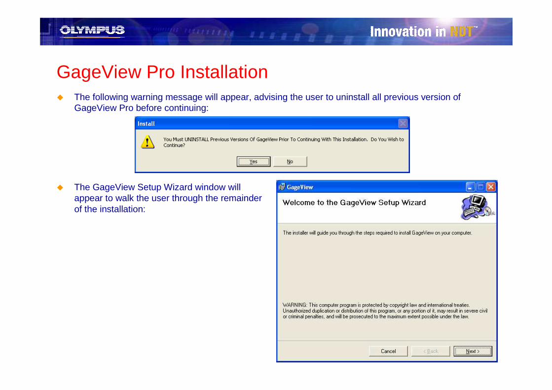
GageView Pro Installation� The following warning message will appear, advising the user to uninstall all previous version of
GageView Pro before continuing:
� The GageView Setup Wizard window will appear to walk the user through the remainder of the installation:
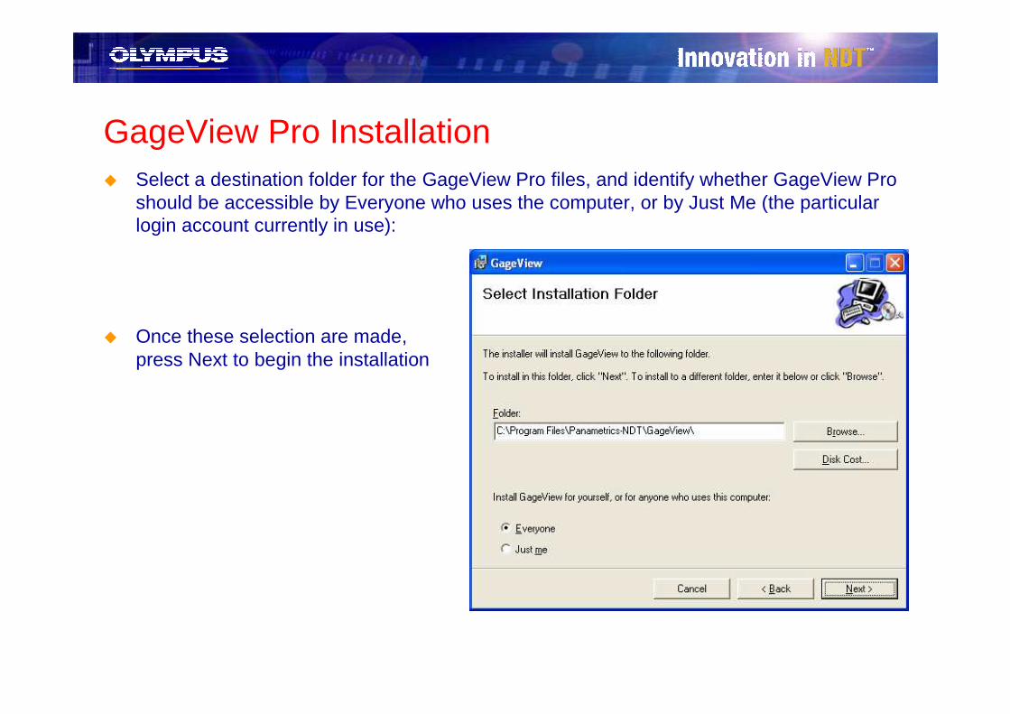
GageView Pro Installation� Select a destination folder for the GageView Pro files, and identify whether GageView Pro
should be accessible by Everyone who uses the computer, or by Just Me (the particular login account currently in use):
� Once these selection are made, press Next to begin the installation

GageView Pro Installation (USB Driver)� After installation of GageView Pro is complete, USB devices require the installation of
other resources.
– EPOCH 4PLUS and EPOCH LT require the installation of a USB driver. Follow the directions included with the GageView Pro installation CD to properly install this driver (see document: Install Device Driver Procedure Pro.rtf)
– EPOCH XT requires installation of Microsoft ActiveSync 4.1. This installation will occur automatically if the user has selected Install All from the main installation menu. ActiveSync can also be installed by running install.exe from the GageView Pro installation CD and selecting Install ActiveSync from the installation menu.

GageView Pro v3.5 Overview

GageView Pro v3.5 Overview
GageView Pro version 3.5 incorporates many new features and updated functionality for the EPOCH series instruments:
� NEW BSCAN review and reporting tools the EPOCH XT and EPOCH 4
� NEW Remote Display updates with useful training and reporting functionality for the EPOCH XT
� NEW EPOCH XT custom measurement setup tool
� NEW Export format overhaul for both EPOCH 4 series and EPOCH XT instruments
3.5.0.0
For Windows 2000/XPCopyright 2004 Olympus NDT
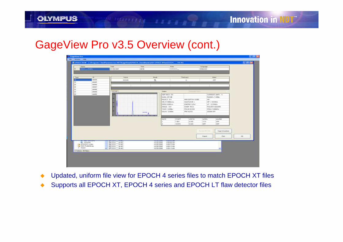
GageView Pro v3.5 Overview (cont.)
� Updated, uniform file view for EPOCH 4 series files to match EPOCH XT files� Supports all EPOCH XT, EPOCH 4 series and EPOCH LT flaw detector files
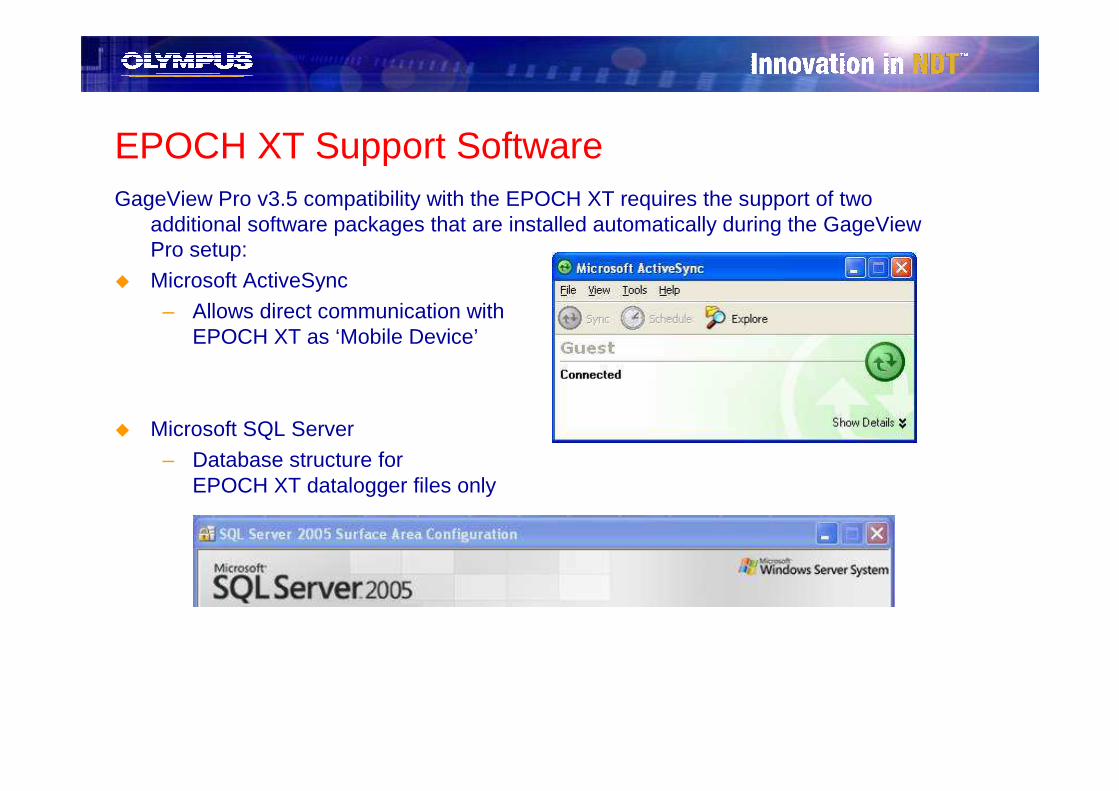
EPOCH XT Support SoftwareGageView Pro v3.5 compatibility with the EPOCH XT requires the support of two
additional software packages that are installed automatically during the GageView Pro setup:
� Microsoft ActiveSync
– Allows direct communication withEPOCH XT as ‘Mobile Device’
� Microsoft SQL Server
– Database structure forEPOCH XT datalogger files only

GageView Pro v3.5 and the EPOCH XT
GageView Pro v3.5 provides full compatibility with the EPOCH XT. Features include:
� Download files from the EPOCH XT to PC
� View and Print XT files through GageView Pro� Export data from Survey Files to Microsoft Excel
� Upgrade EPOCH XT embedded software
� Adjust XT settings such as Editable Parameters and Splash Screen display� Monitor the live display of the XT through GageView Pro*
� Directly control all XT functions through GageView Pro
� Create custom DGS/AVG probes for the EPOCH XT probe library
*Live display update rate is between 5-10Hz and is not intended for inspection purposes

Device Initialization
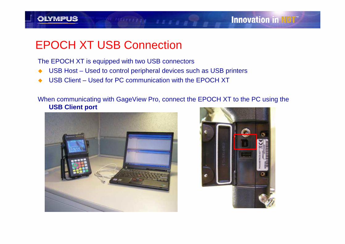
EPOCH XT USB ConnectionThe EPOCH XT is equipped with two USB connectors� USB Host – Used to control peripheral devices such as USB printers
� USB Client – Used for PC communication with the EPOCH XT
When communicating with GageView Pro, connect the EPOCH XT to the PC using the USB Client port
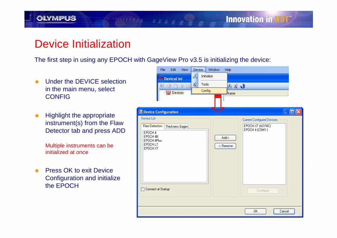
Device InitializationThe first step in using any EPOCH with GageView Pro v3.5 is initializing the device:
� Under the DEVICE selection in the main menu, select CONFIG
� Highlight the appropriate instrument(s) from the Flaw Detector tab and press ADD
Multiple instruments can be initialized at once
� Press OK to exit Device Configuration and initialize the EPOCH

Device Initialization (cont.)Once the EPOCHs have been properly initialized, they will appear as icons under the Device
list in the top frame. Files stored on the instruments are displayed by highlighting the device icon:
Contents of Datalogger on EPOCH XT
File Wizard
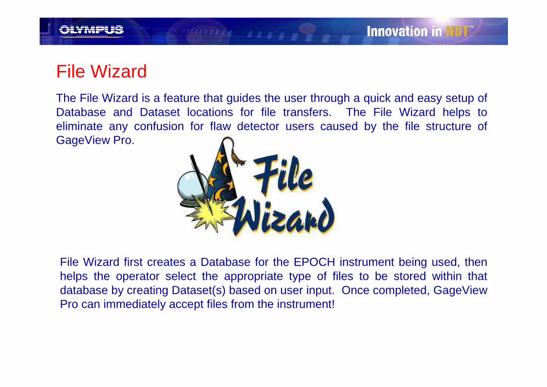
File WizardThe File Wizard is a feature that guides the user through a quick and easy setup of Database and Dataset locations for file transfers. The File Wizard helps to eliminate any confusion for flaw detector users caused by the file structure of GageView Pro.
File Wizard first creates a Database for the EPOCH instrument being used, then helps the operator select the appropriate type of files to be stored within that database by creating Dataset(s) based on user input. Once completed, GageView Pro can immediately accept files from the instrument!
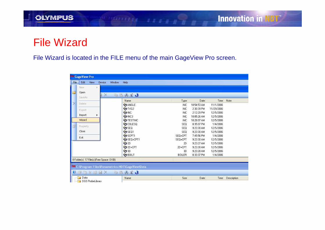
File WizardFile Wizard is located in the FILE menu of the main GageView Pro screen.

File Wizard – STEP 1� Select the instrument or instruments that will be connected to GageView Pro for file
downloads
– Highlight the instrument(s) in the left column
– Press the ADD button to select the instrument(s) for setup
– Press NEXT to continue
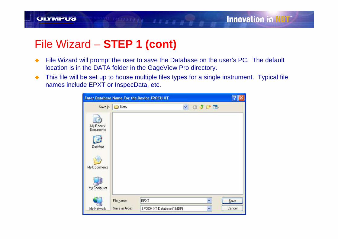
File Wizard – STEP 1 (cont)� File Wizard will prompt the user to save the Database on the user’s PC. The default
location is in the DATA folder in the GageView Pro directory.
� This file will be set up to house multiple files types for a single instrument. Typical file names include EPXT or InspecData, etc.
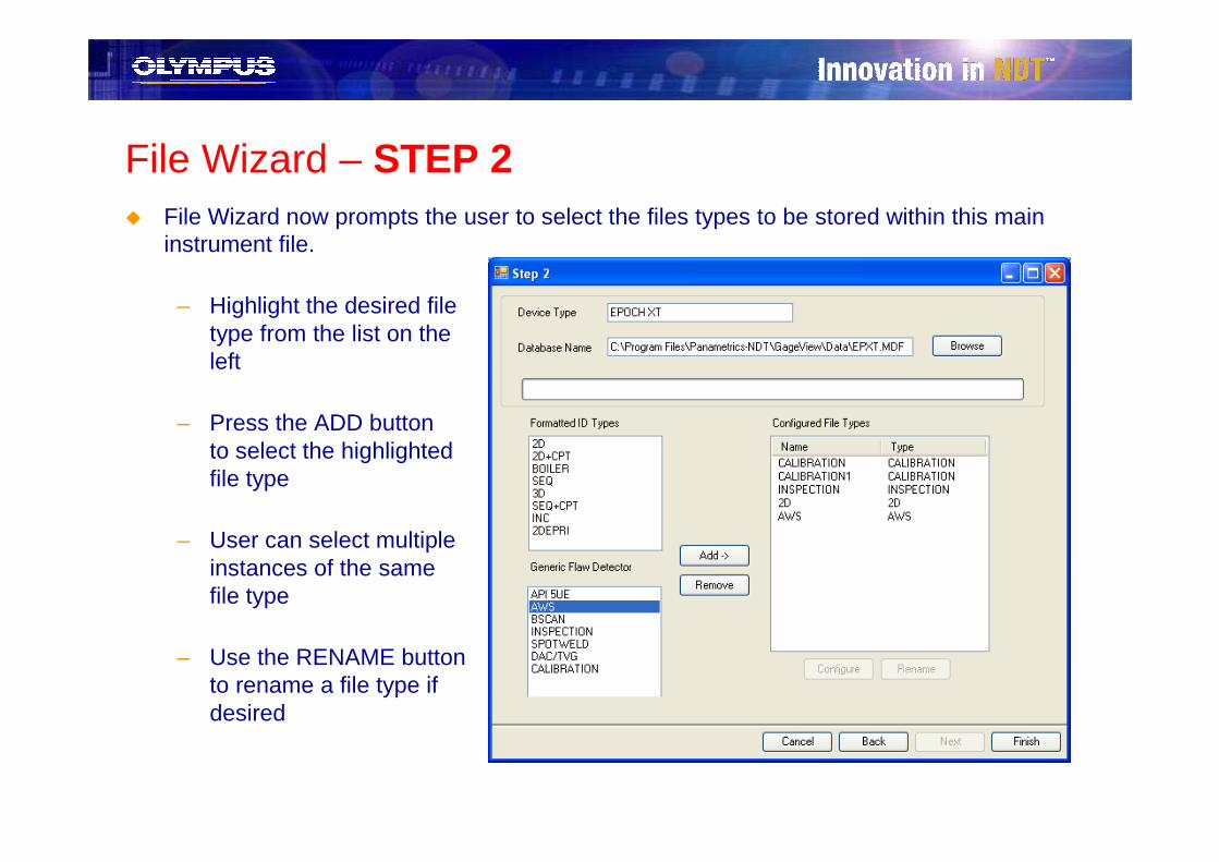
File Wizard – STEP 2� File Wizard now prompts the user to select the files types to be stored within this main
instrument file.
– Highlight the desired filetype from the list on theleft
– Press the ADD buttonto select the highlightedfile type
– User can select multipleinstances of the samefile type
– Use the RENAME buttonto rename a file type ifdesired

File Wizard – STEP 2� Generic Flaw Detector file types will accept all files from the EPOCH XT and are used
as a general storage space for any EPOCH XT information stored in the datalogger.
� Formatted ID Types have specific, user-defined file structures that require additional setup. When a Formatted ID Type is selected, the user is immediately brought to a new setup screen that requires user input to define the file criteria
*Example to the right shows the setup for a 2D file type
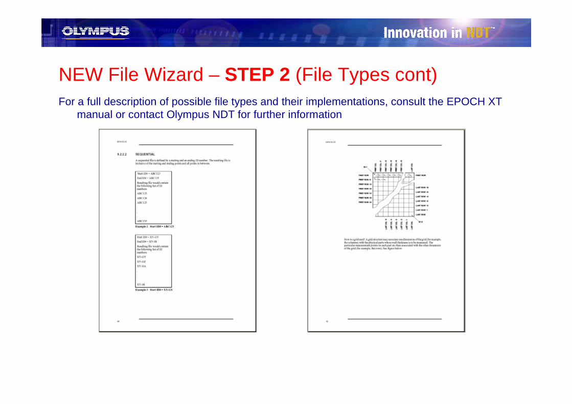
NEW File Wizard – STEP 2 (File Types cont)For a full description of possible file types and their implementations, consult the EPOCH XT
manual or contact Olympus NDT for further information

File Wizard - FINISH� When all desired file types have been selected and properly setup, press the FINISH
button to create the corresponding Database and Datasets
� The Database name created in STEP 1 displays below the Data folder in GageView Pro
� The Datasets created in STEP 2 display within the Database and are ready to receive file transfers from the instrument (EPOCH XT in the above example)
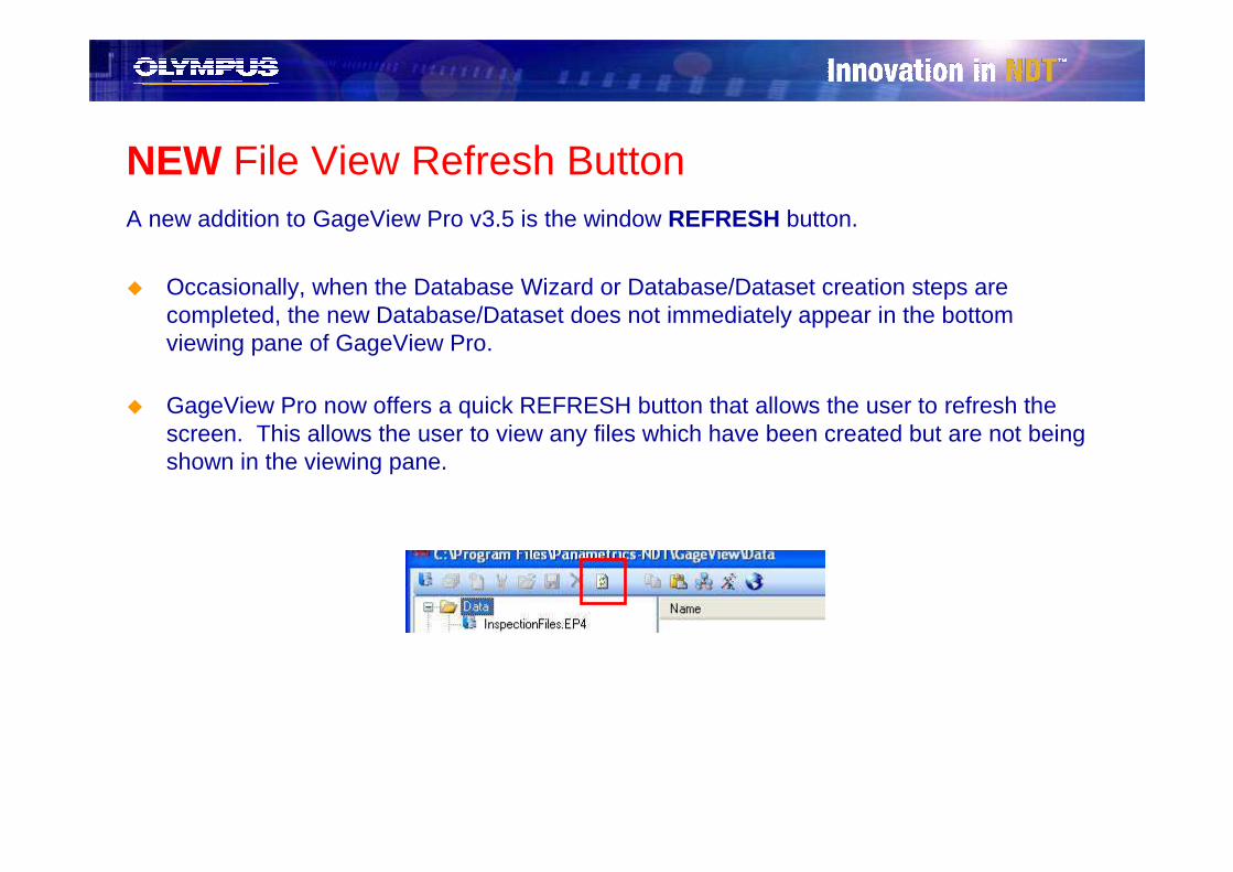
NEW File View Refresh ButtonA new addition to GageView Pro v3.5 is the window REFRESH button.
� Occasionally, when the Database Wizard or Database/Dataset creation steps are completed, the new Database/Dataset does not immediately appear in the bottom viewing pane of GageView Pro.
� GageView Pro now offers a quick REFRESH button that allows the user to refresh the screen. This allows the user to view any files which have been created but are not being shown in the viewing pane.

Manual File Structure Setup

Database Setup - ManualThe GageView Pro Database houses various file types and file structures for a particular
instrument. Each Database is unique to its particular instrument*, and within the Database, an operator must set up file locations to allow file transfers.
� GageView Pro allows the operator to manually set up a Database location on the PC where new Datasets and/or files can be transferred. To set up a new Database:
– Under the FILE menu, selectNEW>DATABASE,
-or-
– Click the NEW DATABASEicon in the lower GageViewPro view pane
or
*EPOCH 4 and EPOCH LT instruments use the SAME Data base structure
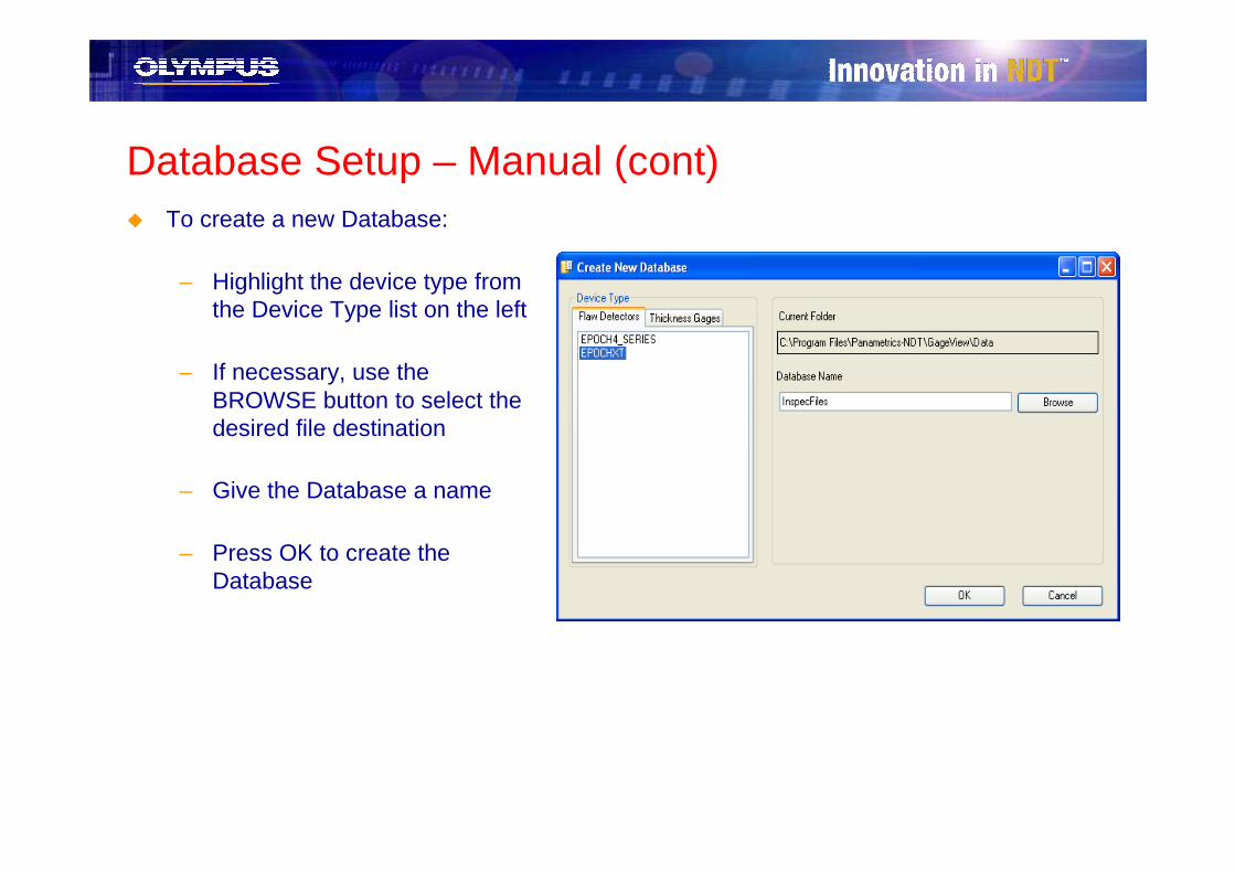
Database Setup – Manual (cont)� To create a new Database:
– Highlight the device type from the Device Type list on the left
– If necessary, use the BROWSE button to select the desired file destination
– Give the Database a name
– Press OK to create the Database

Database Setup – Manual (cont)
The Database is now created and should appear in the lower GageView Pro view pane

Dataset Setup - ManualGageView Pro Datasets are specific file storage locations. Generic flaw detector Datasets
allow the user to transfer any flaw detector file for a particular instrument to and from GageView Pro. Datasets can also specifically define the structure of files stored within a particular Database, such as a 2D or 3D grid file. New blank template files, often called SURVEYs, can also be created within a Dataset.
� GageView Pro allows the operator to manually set up Datasets within a Database where files can be stored and/or created. To set up a new Dataset:
– Highlight the desired Database location for thenew Dataset
– Under the FILE menu, selectNEW>DATASET,
-or-
– Click the NEW DATASETicon in the lower GageViewPro view pane
or

Dataset Setup – Manual (STEP 1)� Create a Dataset Name:
Dataset names are typically chosen to reflect either the structure of the files within the Dataset (i.e. 2D) or the type of files to be stored within the Dataset (i.e. CALIBRATION)
� Define the FORMAT of the files within the Dataset (Dataset Type) from the drop down menu
� Use the NOTE field to adda short description to the Dataset (optional)
� Press the NEXT button to proceed to the next step
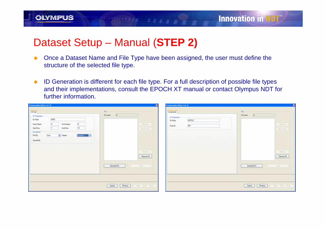
Dataset Setup – Manual (STEP 2)� Once a Dataset Name and File Type have been assigned, the user must define the
structure of the selected file type.
� ID Generation is different for each file type. For a full description of possible file types and their implementations, consult the EPOCH XT manual or contact Olympus NDT for further information.
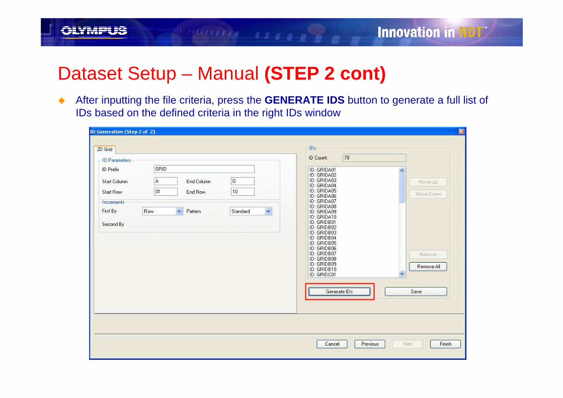
Dataset Setup – Manual (STEP 2 cont)� After inputting the file criteria, press the GENERATE IDS button to generate a full list of
IDs based on the defined criteria in the right IDs window

Dataset Setup – FINISH� If satisfied with the generated ID list
– Press the SAVE button to save the current list of IDs
– Press the FINISH button to complete the Dataset setup process
� The new Dataset will appear under its assigned Database in the lower GageView Pro view pane
� The Dataset is now ready to accept file transfers of files from the EPOCH XT
� IMPORTANT Datasets will ONLY store files that match the Dataset file typecriteria EXACTLY.
– Example: A 3D grid file cannot be stored in a 2D grid Dataset– Example: A 2D grid file with 10 columns cannot be stored in a 2D Dataset defined
with 5 columns
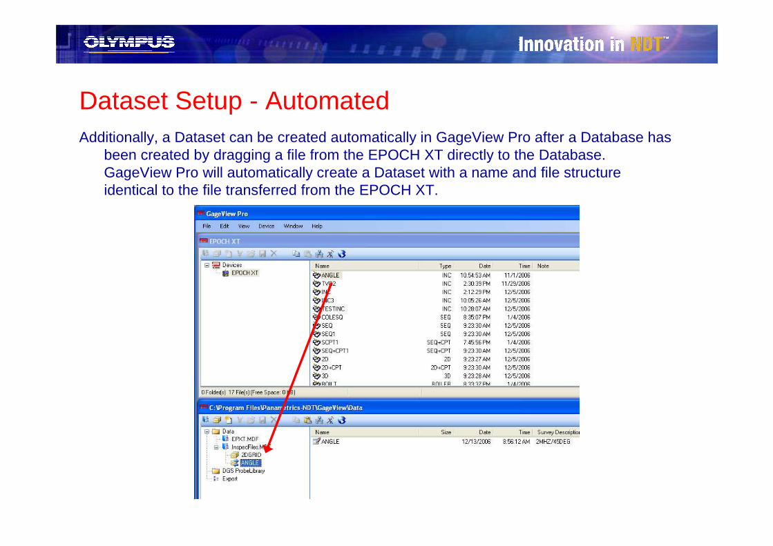
Dataset Setup - AutomatedAdditionally, a Dataset can be created automatically in GageView Pro after a Database has
been created by dragging a file from the EPOCH XT directly to the Database. GageView Pro will automatically create a Dataset with a name and file structure identical to the file transferred from the EPOCH XT.

NEW File View Refresh ButtonA new addition to GageView Pro v3.5 is the window REFRESH button.
� Occasionally, when the Database Wizard or Database/Dataset creation steps are completed, the new Database/Dataset does not immediately appear in the bottom viewing pane of GageView Pro.
� GageView Pro now offers a quick REFRESH button that allows the user to refresh the screen. This allows the user to view any files which have been created but are not being shown in the viewing pane.

Files and File Transfers

File TransfersOnce a Database and Dataset are setup in GageView Pro (see previous sections), files can
easily be transferred between GageView Pro and the attached EPOCH(s)
� To download files from an instrument
– Highlight the file in the topGageView Pro view pane
– Click and drag this file fromthe EPOCH to theDataset* created in thebottom GageView Pro viewpane
*IMPORTANT EPOCH XT Datasets will ONLY store files that match the Dataset file type criteria EXACTLY (Examples: A 3D grid file cannot be stored in a 2D grid Dataset, and a 2D gri d file with 10 columns cannot be stored in a 2D Dat aset defined with 5 columns)

File Transfers (cont)� To upload files from GageView Pro to an EPOCH
– Highlight the file in the bottomGageView Pro view pane
– Click and drag this file fromGageView Pro to the EPOCH in the top GageView Pro viewpane
WARNING Some files, such as large grid files, have complicated structures and may take longer to transfer to an EPOCH XT! Please allow up to a few minutes for the upload to be completed!
Survey Files
� When a new Dataset is created with file criteria/structure, a blank data file is automatically generated within that Dataset
� This blank file is called a Survey file and is named after the Dataset
� Survey files are template files that have the same file structure as their parent Datasets but have NO inspection data stored in the file
� Survey files can be renamed and uploaded to the EPOCH instrument multiple times to create empty inspection files on the instrument ready to acquire data within the file structure of a particular Dataset
– Allows for easy downloading to the same Dataset for multiple inspections
– Allows for logical layout of inspection plan prior to field work
� Survey files are NOT created with Generic Flaw Detector datasets (see File Wizard setup)
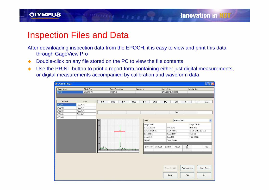
Inspection Files and DataAfter downloading inspection data from the EPOCH, it is easy to view and print this data
through GageView Pro
� Double-click on any file stored on the PC to view the file contents
� Use the PRINT button to print a report form containing either just digital measurements, or digital measurements accompanied by calibration and waveform data
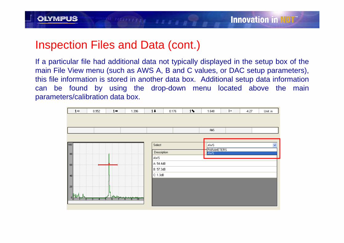
Inspection Files and Data (cont.)If a particular file had additional data not typically displayed in the setup box of the main File View menu (such as AWS A, B and C values, or DAC setup parameters), this file information is stored in another data box. Additional setup data information can be found by using the drop-down menu located above the main parameters/calibration data box.
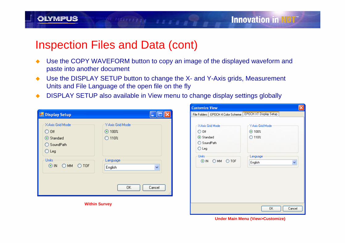
Inspection Files and Data (cont)� Use the COPY WAVEFORM button to copy an image of the displayed waveform and
paste into another document
� Use the DISPLAY SETUP button to change the X- and Y-Axis grids, Measurement Units and File Language of the open file on the fly
� DISPLAY SETUP also available in View menu to change display settings globally
Within Survey
Under Main Menu (View>Customize)
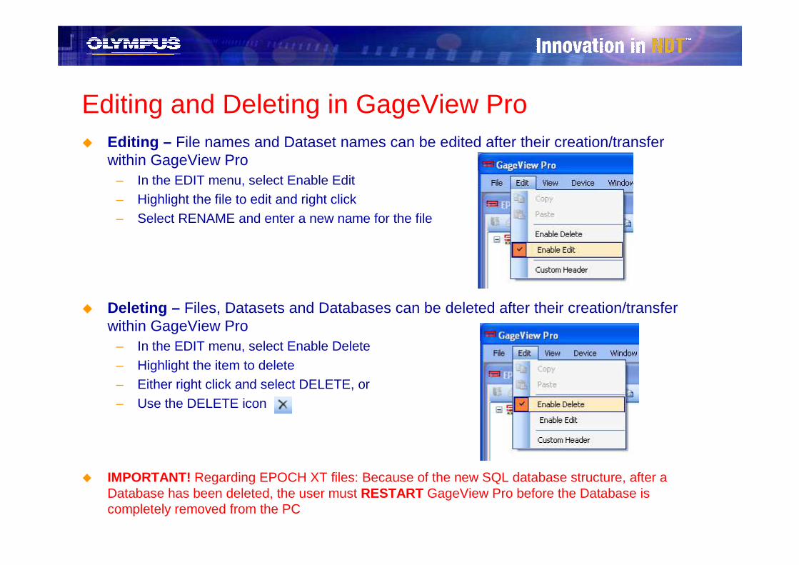
Editing and Deleting in GageView Pro� Editing – File names and Dataset names can be edited after their creation/transfer
within GageView Pro– In the EDIT menu, select Enable Edit– Highlight the file to edit and right click– Select RENAME and enter a new name for the file
� Deleting – Files, Datasets and Databases can be deleted after their creation/transfer within GageView Pro
– In the EDIT menu, select Enable Delete– Highlight the item to delete– Either right click and select DELETE, or– Use the DELETE icon
� IMPORTANT! Regarding EPOCH XT files: Because of the new SQL database structure, after a Database has been deleted, the user must RESTART GageView Pro before the Database is completely removed from the PC

Survey Data Exporting
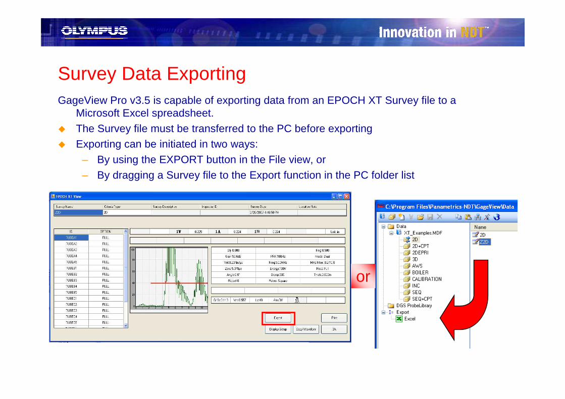
Survey Data ExportingGageView Pro v3.5 is capable of exporting data from an EPOCH XT Survey file to a
Microsoft Excel spreadsheet.
� The Survey file must be transferred to the PC before exporting� Exporting can be initiated in two ways:
– By using the EXPORT button in the File view, or
– By dragging a Survey file to the Export function in the PC folder list
or
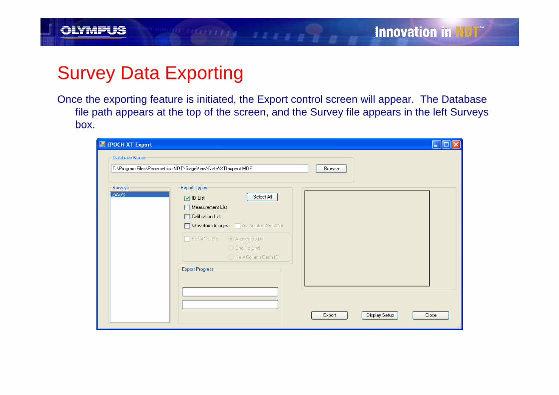
Survey Data ExportingOnce the exporting feature is initiated, the Export control screen will appear. The Database
file path appears at the top of the screen, and the Survey file appears in the left Surveysbox.
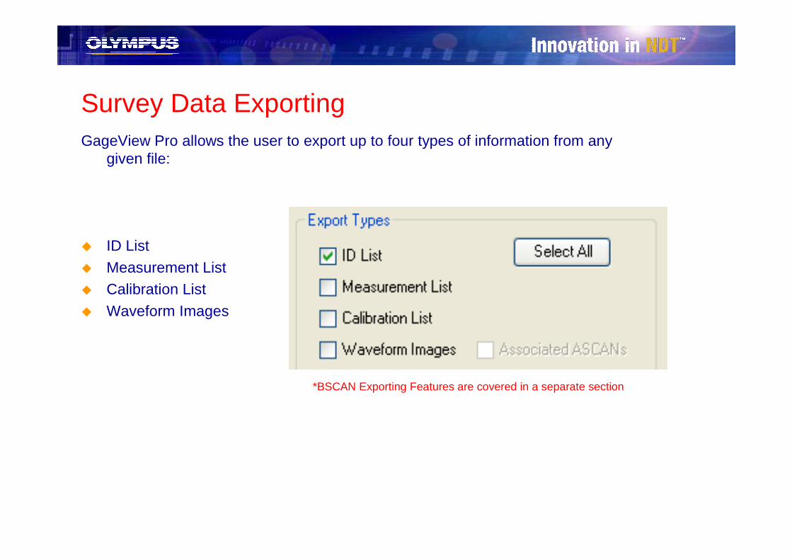
Survey Data ExportingGageView Pro allows the user to export up to four types of information from any
given file:
� ID List
� Measurement List� Calibration List
� Waveform Images
*BSCAN Exporting Features are covered in a separate section

Survey Data: Export Types – ID List� ID List: This export type provides all digital measurements (up to five) saved
on the EPOCH XT within the current survey (data) file.
– The information for each ID is listed in a separate row, and each column contains measurement information for the ID
– Numeric measurements are separated from their corresponding units of measurement by column
– Alarm conditions are included if present
– Leg information is displayed for angle inspection– Special data (such as A, B and C values for AWS inspections) is also listed
– NEW Clicking on the hyperlink in the Type category will jump the user to the waveform view of the corresponding ID name, when one exists

Survey Data: Export Types – Measurement List� Measurement List: This export type provides descriptions of the digital
measurements made for each ID. Since the EPOCH XT allows up to five customizable digital measurements, the user may need to correlate the numerical measurements from the ID List export with the definitions from the Measurements List export.
– The information for each ID is listed in a separate row, and each column contains measurement information for the ID
– Gate measurement mode (Peak, Edge or 1st Peak) is included for each ID

Survey Data: Export Types – Calibration List� Calibration List: This export type details the instrument calibration settings for
each ID at the time of save. – Data for each ID is separated by column
– Each calibration parameter is separated by row
– Each calibration parameter row is consistent across all IDs, despite setup, for easy comparison of settings from ID to ID
– NEW Clicking on the hyperlink in the cell containing the ID name will jump the user to the waveform view of the corresponding ID name, when one exists
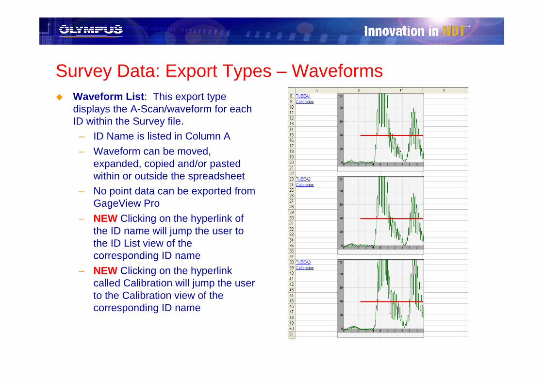
Survey Data: Export Types – Waveforms� Waveform List: This export type
displays the A-Scan/waveform for each ID within the Survey file.
– ID Name is listed in Column A
– Waveform can be moved, expanded, copied and/or pasted within or outside the spreadsheet
– No point data can be exported from GageView Pro
– NEW Clicking on the hyperlink of the ID name will jump the user to the ID List view of the corresponding ID name
– NEW Clicking on the hyperlink called Calibration will jump the user to the Calibration view of the corresponding ID name
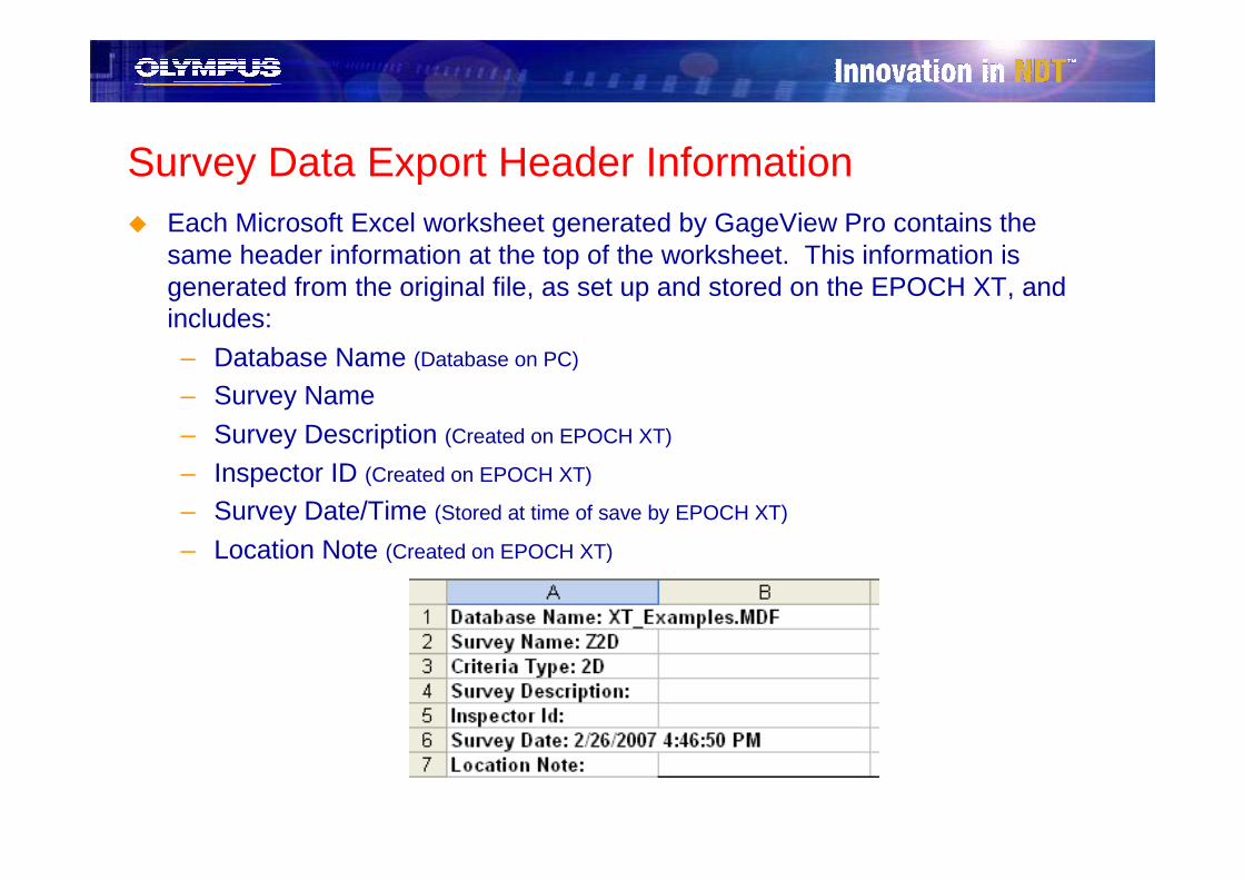
Survey Data Export Header Information� Each Microsoft Excel worksheet generated by GageView Pro contains the
same header information at the top of the worksheet. This information is generated from the original file, as set up and stored on the EPOCH XT, and includes:
– Database Name (Database on PC)
– Survey Name
– Survey Description (Created on EPOCH XT)
– Inspector ID (Created on EPOCH XT)
– Survey Date/Time (Stored at time of save by EPOCH XT)
– Location Note (Created on EPOCH XT)

BSCAN Review and Export

NEW EPOCH XT BSCAN CompatibilityIn March 2008, Olympus NDT released BSCAN capabilities on the EPOCH XT flaw detector. An important component of BSCAN for nearly every customer using the technique is data collection, analysis, and reporting.
GageView Pro has been updated to be fully compatible with the EPOCH XT’s BSCAN feature, and to provide enhanced reporting and analysis functions.

NEW BSCAN – File ManagementEPOCH XT BSCAN files are managed and viewed using the same procedures as any other EPOCH XT data file.
� BSCAN data can be stored in any of the file types available on the EPOCH XT, including Incremental, Sequential, 2D Grid, etc. The same file criteria rules apply when downloading BSCAN data to a Dataset in GageView Pro as any other file.
� Functions such as Print, Export, Copy Waveform, etc, are all accessed in the same way as file types discussed in previous sections of this presentation.
� This presentation section will cover only functionality unique to BSCAN data files.

NEW BSCAN – File ViewThe File View of an EPOCH XT BSCAN data file has some additional components as compared to a more standard inspection file.
Compressed BSCAN Image
Review BSCAN Launch Button
File Info Drop-Down Menu
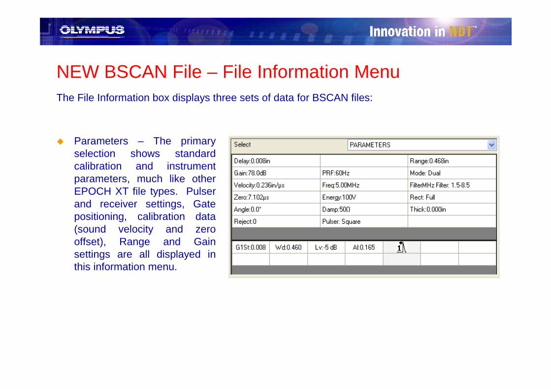
NEW BSCAN File – File Information MenuThe File Information box displays three sets of data for BSCAN files:
� Parameters – The primary selection shows standard calibration and instrument parameters, much like other EPOCH XT file types. Pulser and receiver settings, Gate positioning, calibration data (sound velocity and zero offset), Range and Gain settings are all displayed in this information menu.
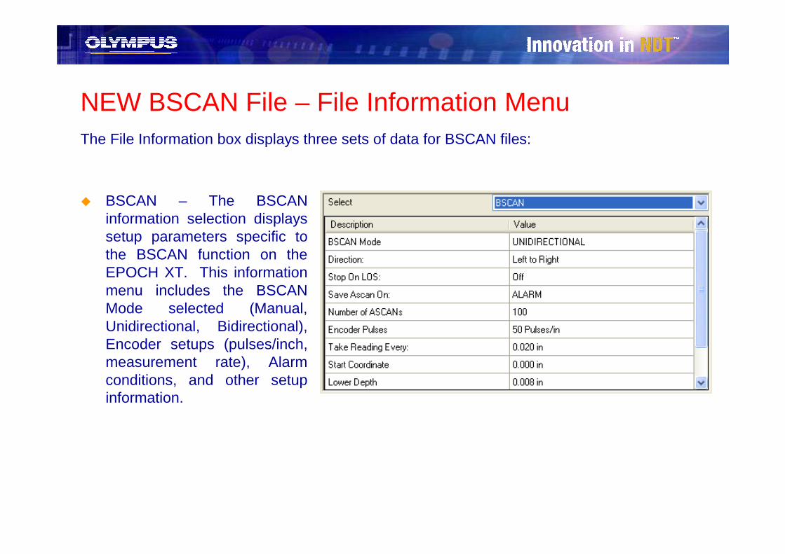
NEW BSCAN File – File Information MenuThe File Information box displays three sets of data for BSCAN files:
� BSCAN – The BSCAN information selection displays setup parameters specific to the BSCAN function on the EPOCH XT. This information menu includes the BSCAN Mode selected (Manual, Unidirectional, Bidirectional), Encoder setups (pulses/inch, measurement rate), Alarm conditions, and other setup information.
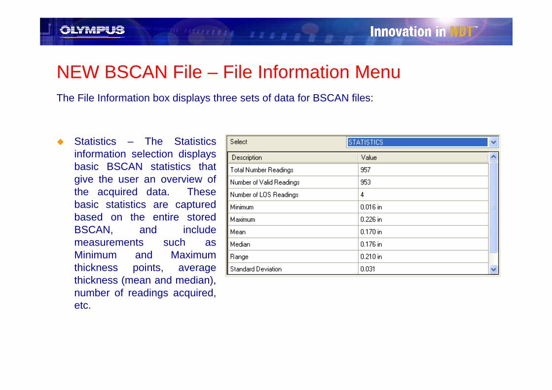
NEW BSCAN File – File Information MenuThe File Information box displays three sets of data for BSCAN files:
� Statistics – The Statistics information selection displays basic BSCAN statistics that give the user an overview of the acquired data. These basic statistics are captured based on the entire stored BSCAN, and include measurements such as Minimum and Maximum thickness points, average thickness (mean and median), number of readings acquired, etc.

NEW BSCAN File – BSCAN Data ReviewGageView Pro also provides a more detailed analysis of acquired BSCAN data. The Review BSCAN button allows access to this detailed review of BSCAN data and statistics.

NEW BSCAN File – Statistics BoxThe Review BSCAN window includes an extensive Statistics box, including:
� Overall Stats– Number of acquired points– Average thickness– Standard Deviation, Variance, etc
� Thickness Data– Point by point thickness data– Listed by Index number and Distanced
Travelled (when available)
� Min Data Points� Max Data Points
� LOS Data Points
� ASCAN Data Points– List of Index/DT points where an
ASCAN was acquired
� Min Depth Data Point(s)
� Alarm Data Points– List of Index/DT points where an Alarm
was triggered

NEW BSCAN File – Statistics Box (cont.)The data displayed in each tab of the Statistics Box is collected and calculated based on eitherthe entire saved BSCAN, or an uncompressed window of the BSCAN. The user can select which segment of data to display using two radio buttons next to the Statistics Box.
Thickness Data point list for the entire BSCAN (All Data button selected)
Thickness Data point list for segment of overall BSCAN (Displayed Region button selected)

NEW BSCAN File – BSCAN Image ViewsThe Review BSCAN window provides two views of the acquired BSCAN:
� Compressed – This view shows the entire acquired BSCAN saved within the file. Depending on the length of the BSCAN, some data cannot be displayed in this view because the window only allows a finite number of points to draw the BSCAN.
� Uncompressed – This view shows a segment of the overall acquired BSCAN. Everythickness point of data acquired in the BSCAN is displayed in this view, but the whole BSCAN is not necessarily displayed all at once.
Compressed BSCAN Uncompressed BSCAN
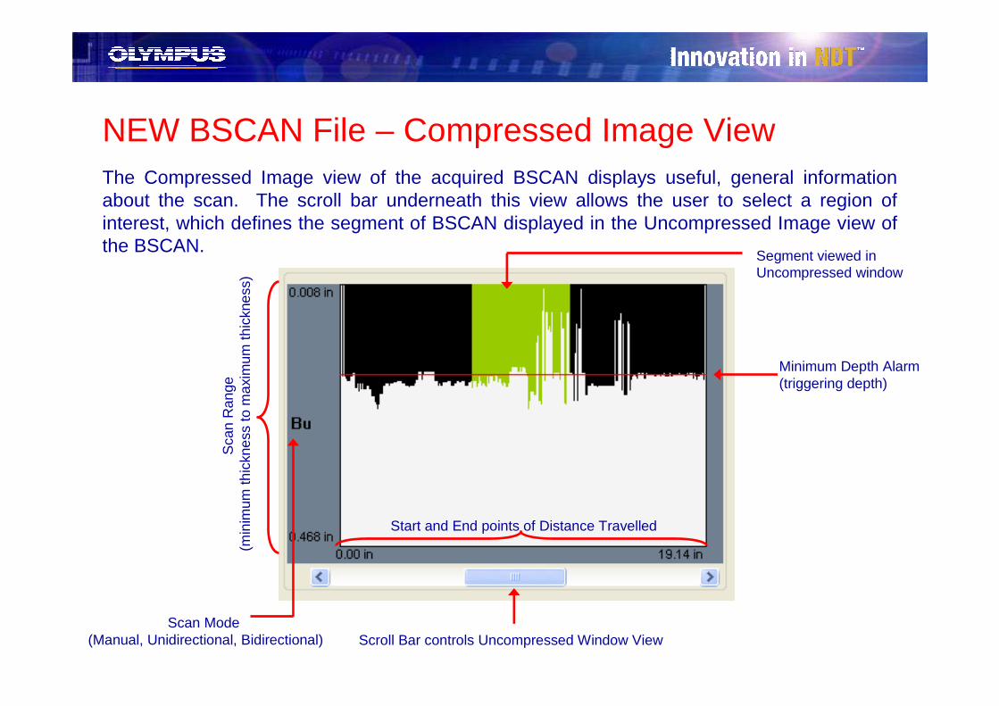
NEW BSCAN File – Compressed Image ViewThe Compressed Image view of the acquired BSCAN displays useful, general informationabout the scan. The scroll bar underneath this view allows the user to select a region of interest, which defines the segment of BSCAN displayed in the Uncompressed Image view of the BSCAN.
Scroll Bar controls Uncompressed Window View
Start and End points of Distance Travelled
Sca
n R
ange
(m
inim
um th
ickn
ess
to m
axim
um th
ickn
ess)
Minimum Depth Alarm(triggering depth)
Scan Mode (Manual, Unidirectional, Bidirectional)
Segment viewed in Uncompressed window
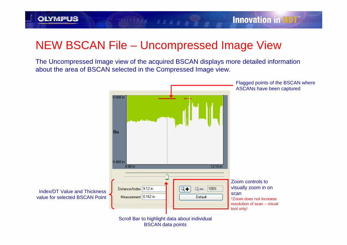
NEW BSCAN File – Uncompressed Image ViewThe Uncompressed Image view of the acquired BSCAN displays more detailed information about the area of BSCAN selected in the Compressed Image view.
Flagged points of the BSCAN where ASCANs have been captured
Scroll Bar to highlight data about individual BSCAN data points
Index/DT Value and Thickness value for selected BSCAN Point
Zoom controls to visually zoom in on scan*Zoom does not increase resolution of scan – visual tool only!

NEW BSCAN File – ASCAN DisplayFor BSCANs where ASCANs are also stored (based on alarm conditions, minimum depth triggers, or other), these ASCANs are also viewed through the Review BSCAN window. IMPORTANT: The user must use the scroll button below the Uncompressed View box to select a unique point where an ASCAN has been saved, and the corresponding ASCAN will appear in the ASCAN window.

NEW BSCAN File – Display StatisticsThe Review BSCAN window features a graphical way of viewing basic BSCAN statistics.
� Use the Show Selected radio buttons to choose a type of statistic to graphically view on the Uncompressed Image view.
� The Review BSCAN window will draw colored lines on the Uncompressed Image view of the BSCAN that correspond with point data or thickness values that match the selected statistic.
� Graphical representation of statistics can be viewed for All Data or Displayed Range, depending on Compute Statistics radio button selection.
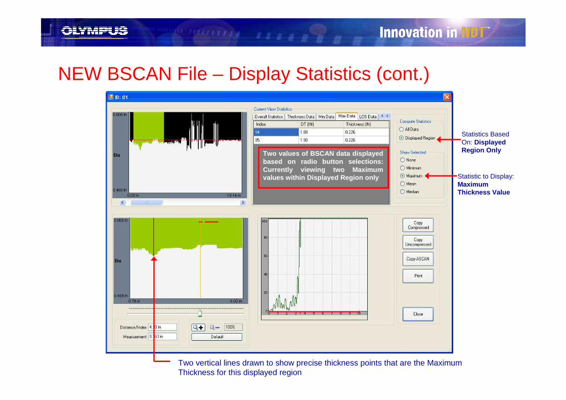
NEW BSCAN File – Display Statistics (cont.)
Statistic to Display: Maximum Thickness Value
Statistics Based On: Displayed Region Only
Two vertical lines drawn to show precise thickness points that are the Maximum Thickness for this displayed region
Two values of BSCAN data displayed based on radio button selections: Currently viewing two Maximumvalues within Displayed Region only
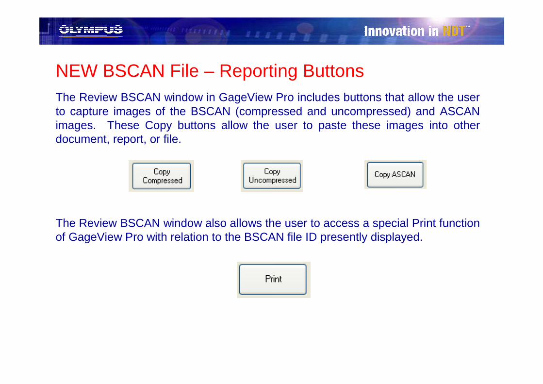
NEW BSCAN File – Reporting Buttons The Review BSCAN window in GageView Pro includes buttons that allow the user to capture images of the BSCAN (compressed and uncompressed) and ASCAN images. These Copy buttons allow the user to paste these images into other document, report, or file.
The Review BSCAN window also allows the user to access a special Print function of GageView Pro with relation to the BSCAN file ID presently displayed.

NEW BSCAN File – BSCAN PrintThe Print function in GageView Pro has been expanded for BSCAN data files to include pertinent information about the BSCAN data. This specialized view is only available when Print is accessed using the button in the Review BSCAN window.
The user can customize this direct print report into four views:
� Images Only (Single Page)– Includes Compressed, Uncompressed and ASCAN images, as well as basic file
information such as Filename and ID name� Images and Calibration Data (2 Pages)
– Includes Compressed, Uncompressed and ASCAN images– Includes all Calibration and ultrasonic setup parameters– Includes all BSCAN setup parameters
� Images and Statistics (2 Pages)– Includes Compressed, Uncompressed and ASCAN images– Includes general Statistics for overall BSCAN
� Images, Calibration Data and Statistics (2 Pages)– Includes Compressed, Uncompressed and ASCAN images– Includes instrument and BSCAN setup/calibration parameters– Includes general Statistics for overall BSCAN

NEW BSCAN File – BSCAN Print
BSCAN Print Example of all data, including images, calibration data and statistics

NEW BSCAN File - ExportThe Export function of GageView Pro has been enhanced to provide more information for BSCAN data files. Users can access this Export feature in the same ways as other Survey files.

NEW BSCAN File – Export (Setup)The Export setup for BSCAN data files is very similar to a standard EPOCH XT file, but with
a few key additions:
� Checking the Waveform Images box will only export Compressed BSCAN images! The user must select to export Associated ASCANs to export stored ASCAN images
� Checking the BSCAN Data box will create a worksheet of BSCAN point data (thickness data) with corresponding index or distance travelled (DT) values
� When exporting BSCAN Data, the operator must choose a method of arranging data:
– Aligned by DT will export point data for every ID in the file. Each ID of point data will be exported side-by-side in columns in the spreadsheet. One column will represent the DT values for all IDs in the file, and the point data will be exported to line up to its corresponding DT value (see example).
– End To End will export point data for every ID in the selected file. The point data will be exported into the same column in the spreadsheet, with each ID’s data exported sequentially
– New Column Each ID will export point data for every ID in the selected file. Each ID will have it’s own column of data and a second column of corresponding DT values. The DT/point data for each ID will not relate, but will be generated row by row.

NEW BSCAN File – Export (Spreadsheet)The export feature for BSCAN files in GageView Pro follows the new, enhanced format of
other EPOCH XT file exports. The BSCAN data files include extra worksheets of exported data, when selected, to display extra BSCAN information.
� ID List – Displays Digital thickness measurements captured during scan, along with alarm conditions
– NEW Click the hyperlink labeled BSCAN in the Type column to jump directly to the BSCAN image of that ID name in the Waveforms worksheet
� Measurement List – Displays labels for digital measurements exported in the ID List worksheet
ID List Worksheet
Measurement List Worksheet

NEW BSCAN File – Export (Spreadsheet)� Calibration List – Displays instrument setup and calibration data for each ID.
– NEW Click the hyperlink labeled as the ID number to jump directly to the BSCAN image of that ID name in the Waveforms worksheet
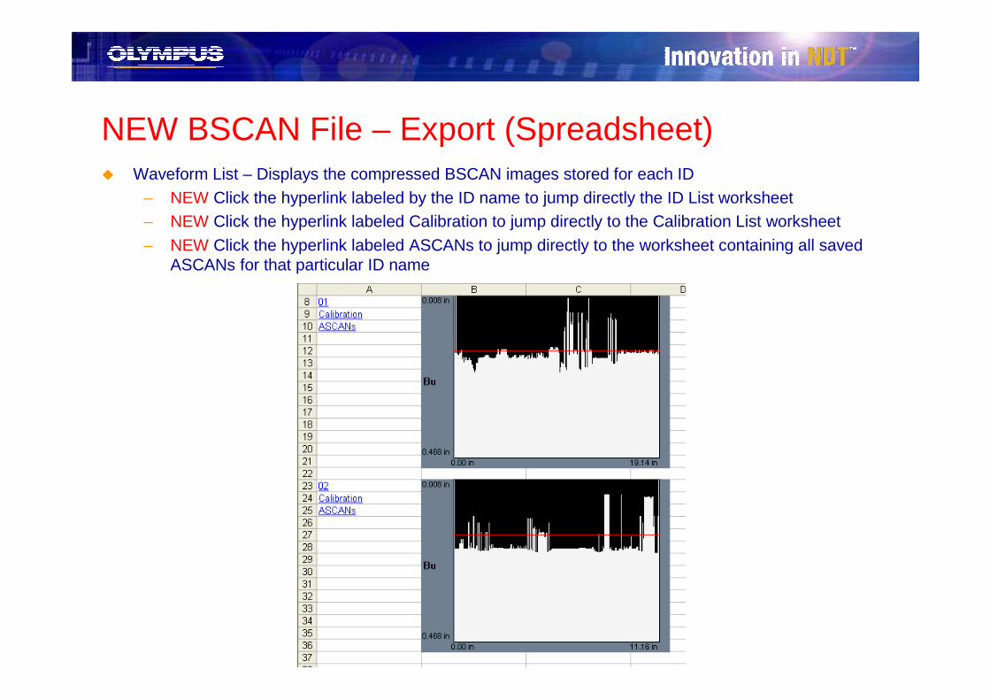
NEW BSCAN File – Export (Spreadsheet)� Waveform List – Displays the compressed BSCAN images stored for each ID
– NEW Click the hyperlink labeled by the ID name to jump directly the ID List worksheet– NEW Click the hyperlink labeled Calibration to jump directly to the Calibration List worksheet– NEW Click the hyperlink labeled ASCANs to jump directly to the worksheet containing all saved
ASCANs for that particular ID name

NEW BSCAN File – Export (Spreadsheet)� ASCANs Worksheet – For every ID that has saved ASCANs, GageView Pro will create a separate
worksheet within the export file (named for the corresponding ID name) that contains:– The compressed BSCAN image– ASCAN images for all saved ASCANs in
that ID– ASCAN images are listed with their
Index/DT point to allow the user to correlate the image to a position on the scan

NEW BSCAN File – Export (Spreadsheet)� BSCAN List – Displays all point data for every BSCAN ID in the exported file.
– Point data listed next to corresponding index/DT value– Data arranged according to user preference in the Export Setup menu (see previous export setup
description)
Two BSCAN IDs exported as New Column Each ID NOTE: Each ID has its own corresponding DT column
Two BSCAN IDs exported as Aligned By DT NOTE: Both IDs correspond to same DT column – when values in ID 01 are not present for DT values in ID 02, blank (LOS) cells are inserted into ID 01 data so scans continue to correspond

Device Tools Menu

Tools MenuGageView Pro’s Device Tools menu has been enhanced for the EPOCH XT. The menu now includes:
� NEW Measurement Setup
� Splash Screen
� Device Info
� Set Options Key
� Remote Display New Features!
� DGS Probe Library
� Editable Parameters
� Upgrade Device Software

Tools Menu – Splash ScreenSplash Screen Tool allows the operator to edit the EPOCH XT’s splash screen
from GageView Pro with multiple lines of information
� Receive the current splash screen from the unit
� Edit the splash screen in GageView Pro
� Transmit the new splash screen to the unit
� Save the splash screen settings in GageView Pro for later use
� Open a saved splash screen file to load onto other units
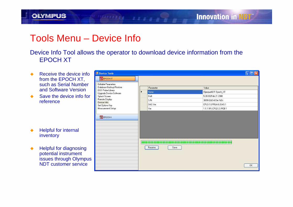
Tools Menu – Device InfoDevice Info Tool allows the operator to download device information from the
EPOCH XT
� Receive the device info from the EPOCH XT, such as Serial Number and Software Version
� Save the device info for reference
� Helpful for internal inventory
� Helpful for diagnosing potential instrument issues through Olympus NDT customer service
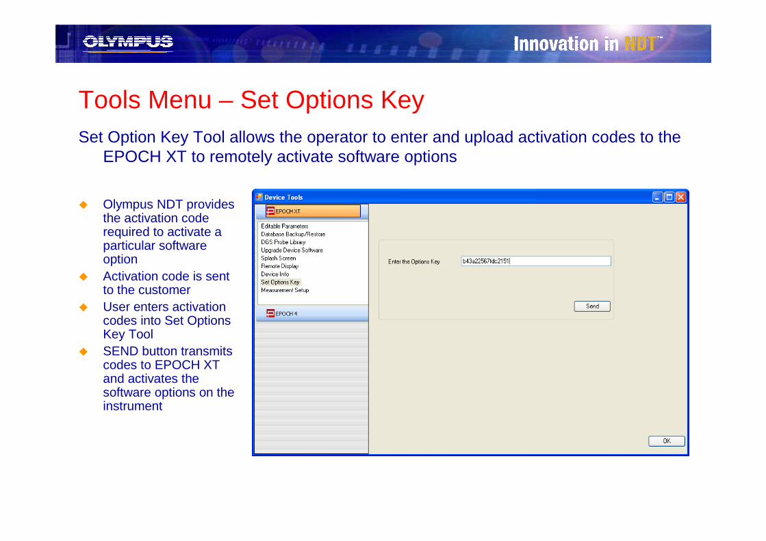
Tools Menu – Set Options KeySet Option Key Tool allows the operator to enter and upload activation codes to the
EPOCH XT to remotely activate software options
� Olympus NDT provides the activation code required to activate a particular software option
� Activation code is sent to the customer
� User enters activation codes into Set Options Key Tool
� SEND button transmits codes to EPOCH XT and activates the software options on the instrument
Tools Menu – Remote DisplayRemote Display Tool is an exciting feature in GageView Pro, and now contains
NEW features!
� Allows the operator to directly control the EPOCH XT through a representation of the XT keypad shown in GageView Pro
� Provides a live, on-screen view of the EPOCH XT display* for viewing on a computer or projector
� Allows the operator to take direct screen captures of the EPOCH XT screen
� Operator can view the live Display and/or EPOCH XT Keypad
� Perfect for training classes, presentations and demonstrations
*Display update in GageView Pro is between 5-10Hz. Not intended for inspection purposes.
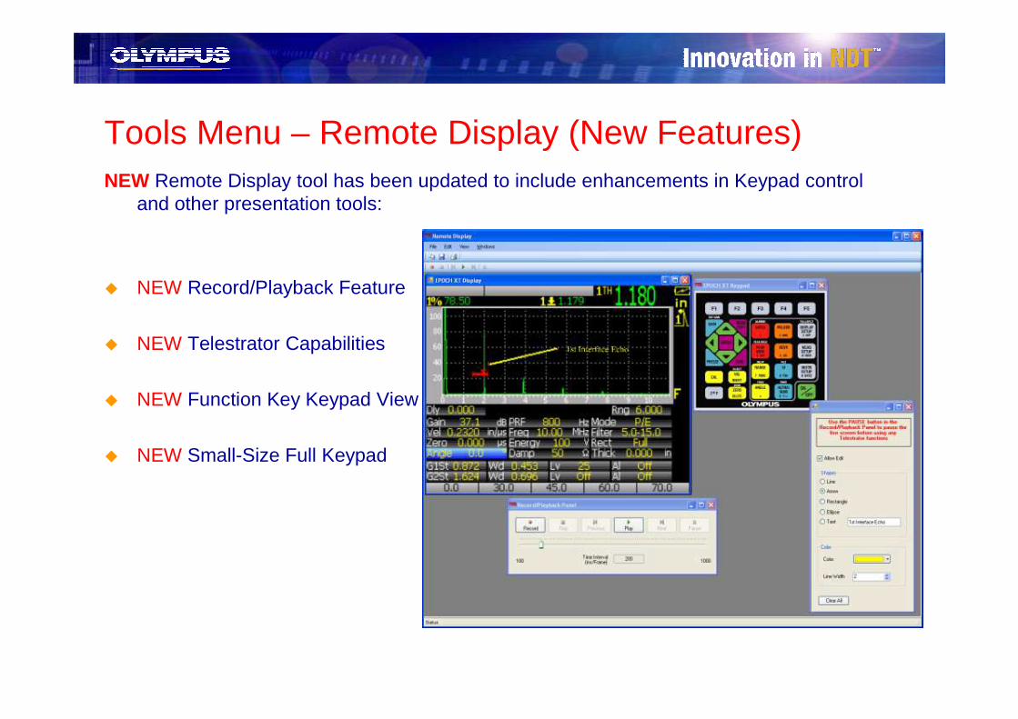
Tools Menu – Remote Display (New Features)NEW Remote Display tool has been updated to include enhancements in Keypad control
and other presentation tools:
� NEW Record/Playback Feature
� NEW Telestrator Capabilities
� NEW Function Key Keypad View
� NEW Small-Size Full Keypad
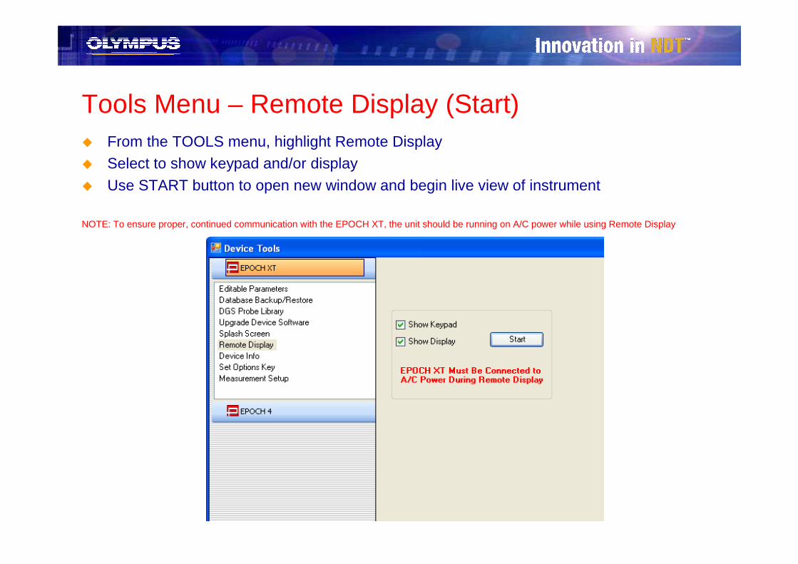
Tools Menu – Remote Display (Start)� From the TOOLS menu, highlight Remote Display� Select to show keypad and/or display
� Use START button to open new window and begin live view of instrument
NOTE: To ensure proper, continued communication with the EPOCH XT, the unit should be running on A/C power while using Remote Display
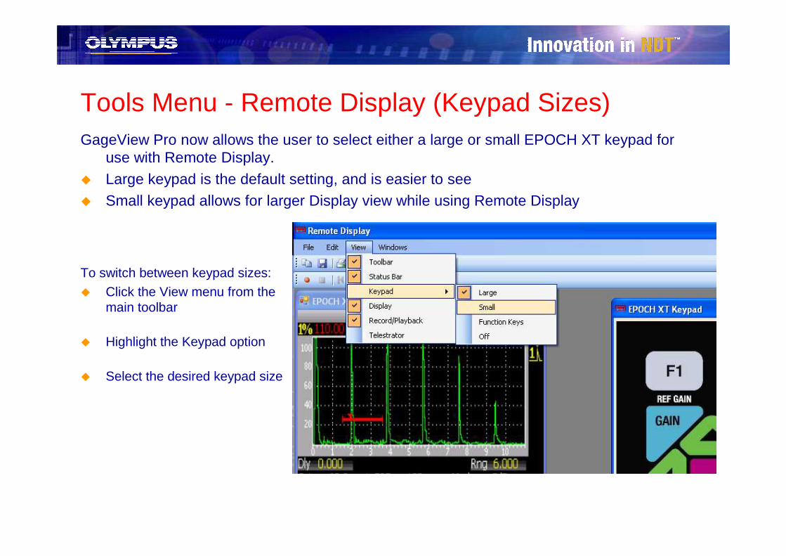
Tools Menu - Remote Display (Keypad Sizes)GageView Pro now allows the user to select either a large or small EPOCH XT keypad for
use with Remote Display.
� Large keypad is the default setting, and is easier to see� Small keypad allows for larger Display view while using Remote Display
To switch between keypad sizes:� Click the View menu from the
main toolbar
� Highlight the Keypad option
� Select the desired keypad size

Tools Menu - Remote Display (‘F’ Function Keypad)GageView Pro now allows the user to only view and operate the ‘F’ Function Keys while in
Remote Display
� Stretch ‘F’ Function Key window to match the width of Display
� Use ‘F’ Function Keys as remote control for EPOCH XT

Tools Menu - Remote Display (Record/Playback)GageView Pro can now capture a live recording of a scan* or procedure using Remote Display
� Record button activates recording
– User is prompted to store the file(s) in a folder*It is recommended to create a unique folder for each individual recording!
� User can select to Use Timed Recording
– Live recording will end after the desired duration of time has expired
� Recording beings when user presses the OK button
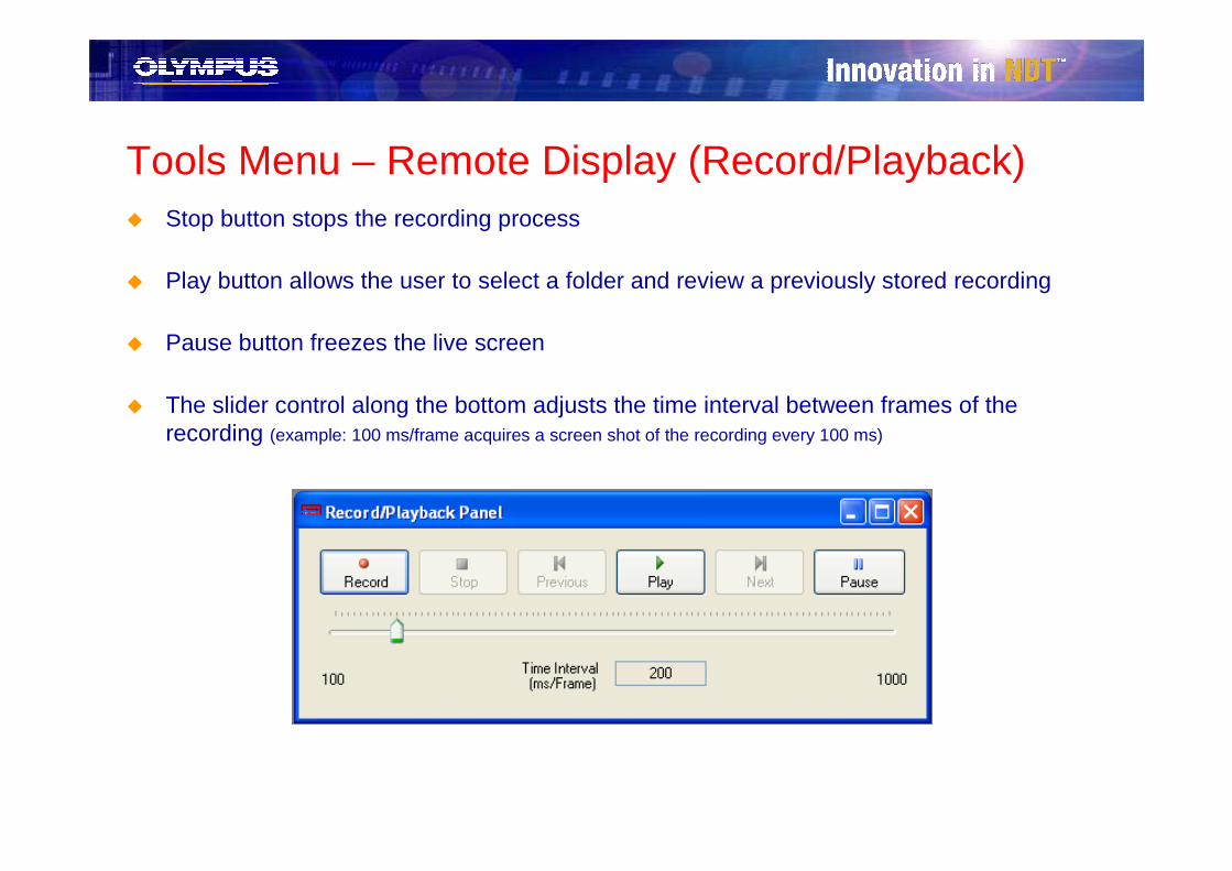
Tools Menu – Remote Display (Record/Playback)� Stop button stops the recording process
� Play button allows the user to select a folder and review a previously stored recording
� Pause button freezes the live screen
� The slider control along the bottom adjusts the time interval between frames of the recording (example: 100 ms/frame acquires a screen shot of the recording every 100 ms)

Tools Menu – Remote Desktop (Telestrator)GageView Pro features Telestrator capabilities using Remote Desktop.
� Useful training tool!� Highlight particular screen captures with
– Arrows
– Text– Circles
– Rectangles
– Lines
� Copy edited screen shot into reports!
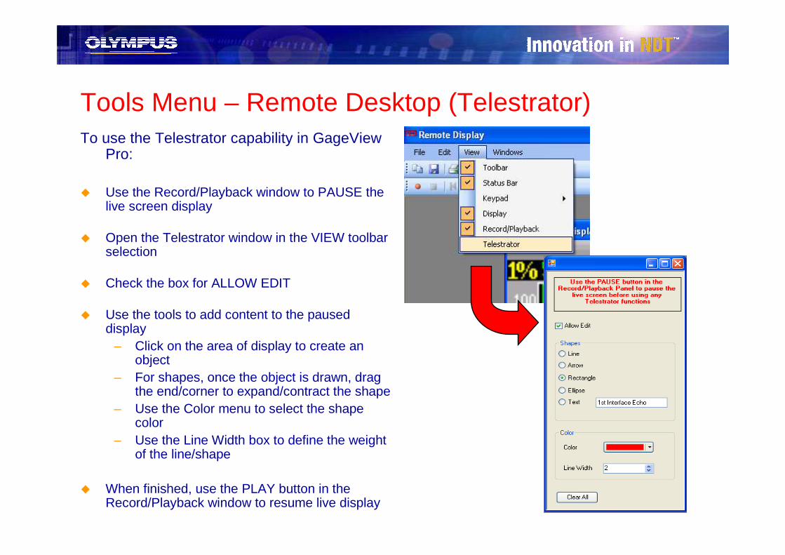
Tools Menu – Remote Desktop (Telestrator)To use the Telestrator capability in GageView
Pro:
� Use the Record/Playback window to PAUSE the live screen display
� Open the Telestrator window in the VIEW toolbar selection
� Check the box for ALLOW EDIT
� Use the tools to add content to the paused display
– Click on the area of display to create an object
– For shapes, once the object is drawn, drag the end/corner to expand/contract the shape
– Use the Color menu to select the shape color
– Use the Line Width box to define the weight of the line/shape
� When finished, use the PLAY button in the Record/Playback window to resume live display

NEW Tools Menu – Measurement Setup
The EPOCH XT now allows the user to choose to automatically adjust its five digital measurement settings based on the instrument setup. This automatic feature displays the most common digital reading settings for inspections such as angle/shearwave, echo-to-echo, and thickness, without forcing the user to manually define which readings should be displayed and saved.
GageView Pro now allows EPOCH XT users to define custom measurement setups on the EPOCH XT! Using the Measurement Setup selection in the Tools menu, the user can set up multiple custom setups to upload to the EPOCH XT. Once uploaded, the user simply has to select that custom measurement set to reset all five digital readings!
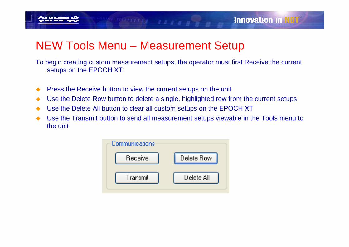
NEW Tools Menu – Measurement SetupTo begin creating custom measurement setups, the operator must first Receive the current
setups on the EPOCH XT:
� Press the Receive button to view the current setups on the unit
� Use the Delete Row button to delete a single, highlighted row from the current setups
� Use the Delete All button to clear all custom setups on the EPOCH XT
� Use the Transmit button to send all measurement setups viewable in the Tools menu to the unit
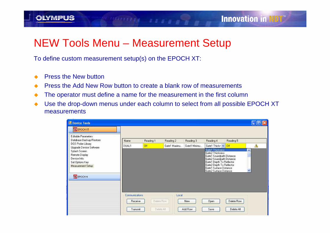
NEW Tools Menu – Measurement SetupTo define custom measurement setup(s) on the EPOCH XT:
� Press the New button
� Press the Add New Row button to create a blank row of measurements� The operator must define a name for the measurement in the first column
� Use the drop-down menus under each column to select from all possible EPOCH XT measurements
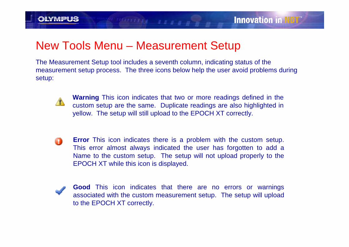
New Tools Menu – Measurement SetupThe Measurement Setup tool includes a seventh column, indicating status of the measurement setup process. The three icons below help the user avoid problems during setup:
Warning This icon indicates that two or more readings defined in the custom setup are the same. Duplicate readings are also highlighted in yellow. The setup will still upload to the EPOCH XT correctly.
Error This icon indicates there is a problem with the custom setup. This error almost always indicated the user has forgotten to add a Name to the custom setup. The setup will not upload properly to the EPOCH XT while this icon is displayed.
Good This icon indicates that there are no errors or warnings associated with the custom measurement setup. The setup will upload to the EPOCH XT correctly.

NEW Tools Menu – Measurement SetupOnce a set of measurements has been created in the Tools menu, the operator can:
� Use the Save button to store the current configuration of measurement setups for later use. These files are stored with the file extension *.MSU, and can only be viewed using GageView Pro.
� Use the Transmit button to send the current configuration of measurement setups to the EPOCH XT.
� Use the Delete Row or Delete All buttons to remove unwanted setups.
� Use the New button to start over.
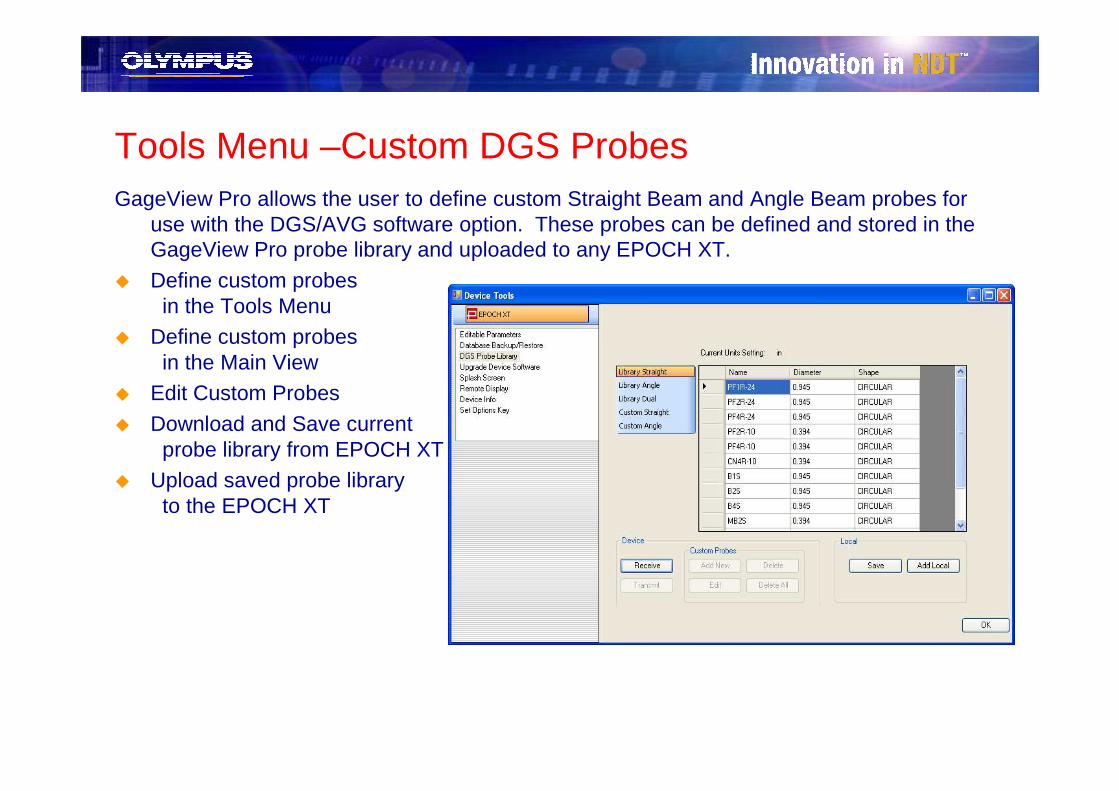
Tools Menu –Custom DGS ProbesGageView Pro allows the user to define custom Straight Beam and Angle Beam probes for
use with the DGS/AVG software option. These probes can be defined and stored in the GageView Pro probe library and uploaded to any EPOCH XT.
� Define custom probes in the Tools Menu
� Define custom probes in the Main View
� Edit Custom Probes
� Download and Save current probe library from EPOCH XT
� Upload saved probe library to the EPOCH XT
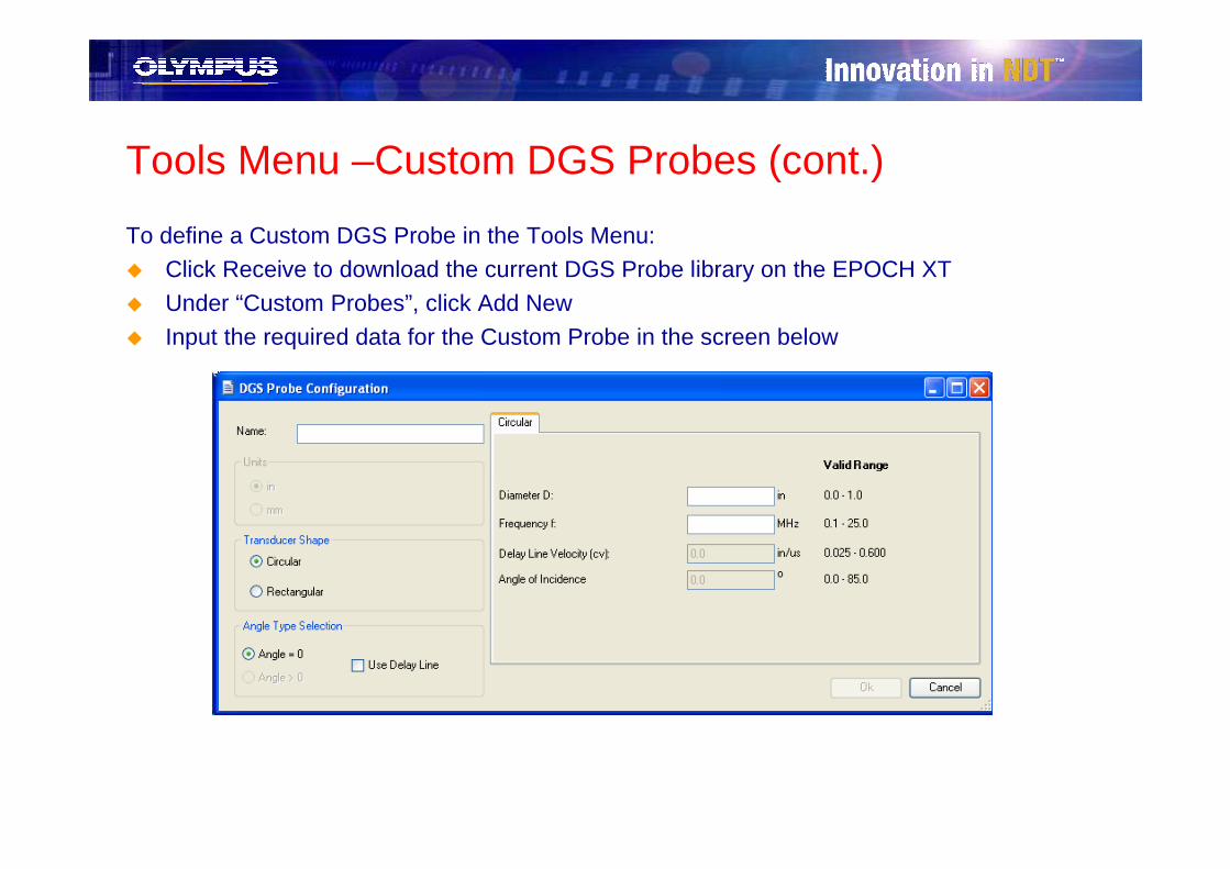
Tools Menu –Custom DGS Probes (cont.)
To define a Custom DGS Probe in the Tools Menu:� Click Receive to download the current DGS Probe library on the EPOCH XT
� Under “Custom Probes”, click Add New
� Input the required data for the Custom Probe in the screen below
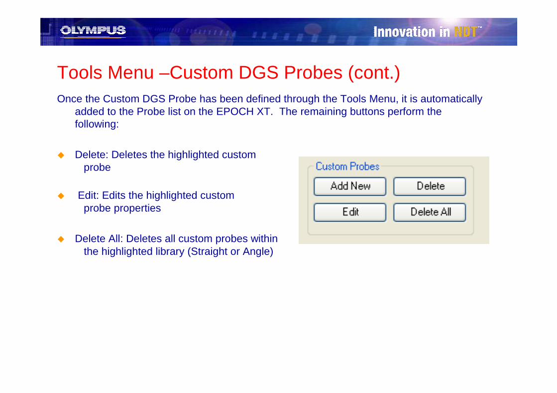
Tools Menu –Custom DGS Probes (cont.)Once the Custom DGS Probe has been defined through the Tools Menu, it is automatically
added to the Probe list on the EPOCH XT. The remaining buttons perform the following:
� Delete: Deletes the highlighted custom probe
� Edit: Edits the highlighted custom probe properties
� Delete All: Deletes all custom probes within the highlighted library (Straight or Angle)

Custom DGS Probes Setup – Main ViewCustom DGS Probes can also be set up in the main GageView Pro window. The PC
pane of this main view contains a folder (under the Data folder) called Probe Library.
� The standard DGS Probe Library is stored in this location for reference under an EPOCH XT Database called Probe.MDF.
� A new Database called LocalProbe.XTPexists to store any custom DGS probes even when they are not loaded on the EPOCH XT.
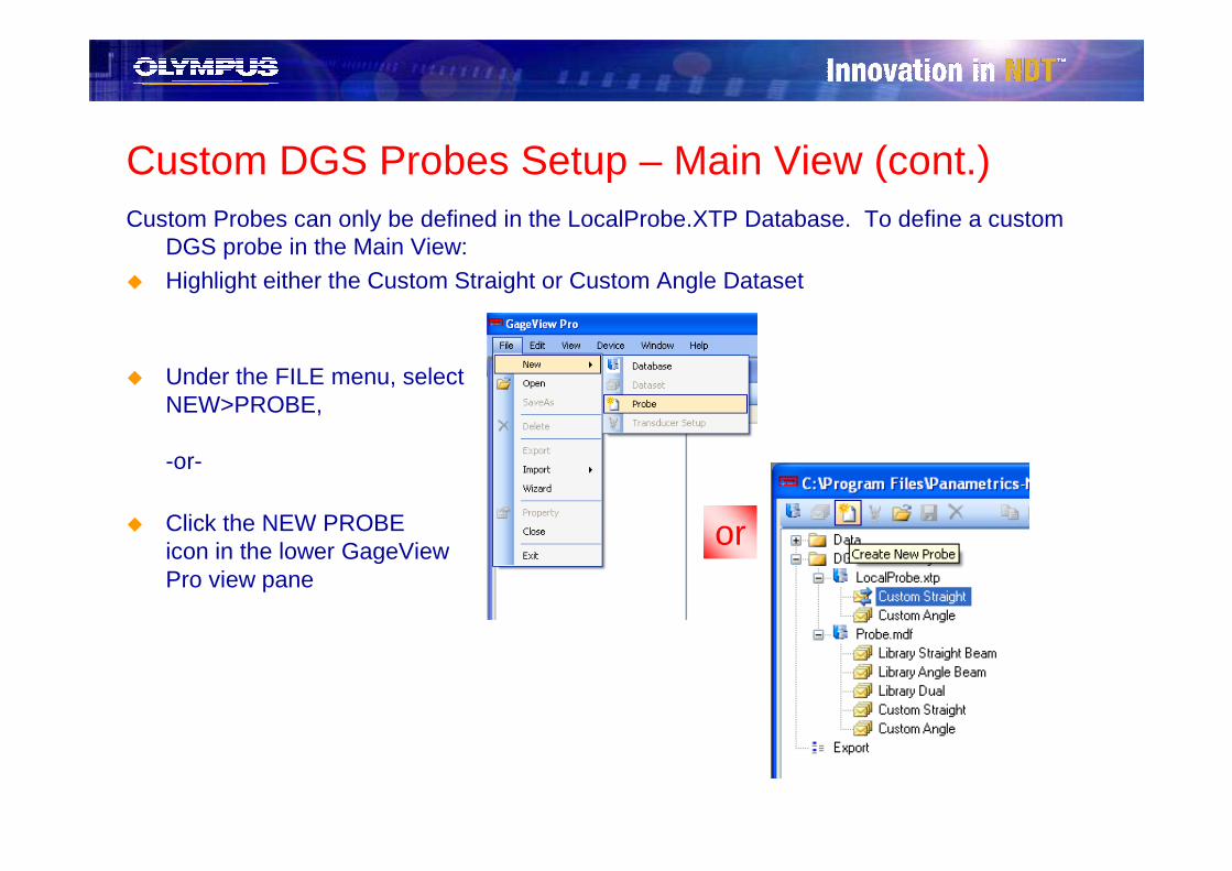
Custom DGS Probes Setup – Main View (cont.)Custom Probes can only be defined in the LocalProbe.XTP Database. To define a custom
DGS probe in the Main View:
� Highlight either the Custom Straight or Custom Angle Dataset
� Under the FILE menu, selectNEW>PROBE,
-or-
� Click the NEW PROBEicon in the lower GageViewPro view pane
or
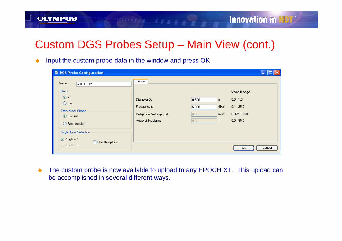
Custom DGS Probes Setup – Main View (cont.)� Input the custom probe data in the window and press OK
� The custom probe is now available to upload to any EPOCH XT. This upload can be accomplished in several different ways.
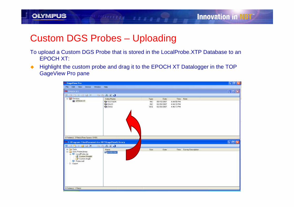
Custom DGS Probes – Uploading To upload a Custom DGS Probe that is stored in the LocalProbe.XTP Database to an
EPOCH XT:
� Highlight the custom probe and drag it to the EPOCH XT Datalogger in the TOP GageView Pro pane
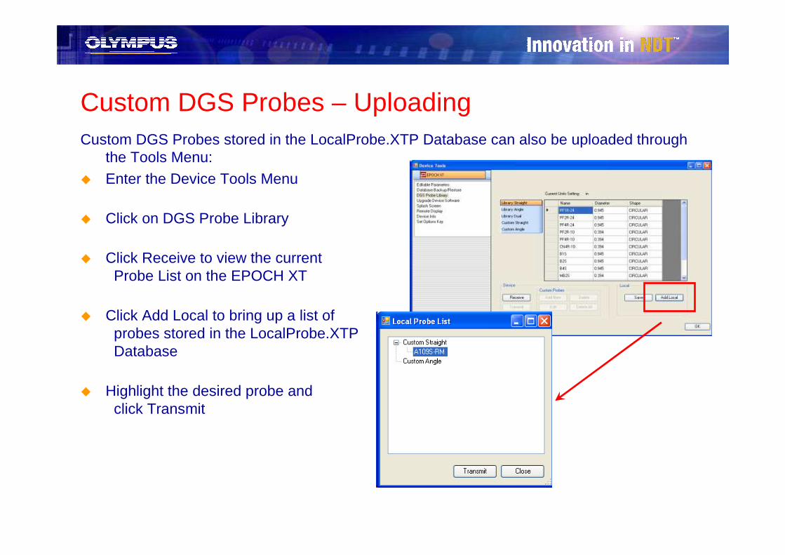
Custom DGS Probes – Uploading Custom DGS Probes stored in the LocalProbe.XTP Database can also be uploaded through
the Tools Menu:
� Enter the Device Tools Menu
� Click on DGS Probe Library
� Click Receive to view the current Probe List on the EPOCH XT
� Click Add Local to bring up a list of probes stored in the LocalProbe.XTPDatabase
� Highlight the desired probe and click Transmit

Custom DGS Probes� Clicking Save in the DGS Probe Library selection of the Tools Menu updated the
Probe.MDF Database in GageView Pro with any custom probes or edits from the connected EPOCH XT. Probes can be copied from Probe.MDF to LocalProbe.XTP
Notes:
� If a DGS calibration or inspection file is stored on a PC via GageView Pro, it can be uploaded to any other EPOCH XT even if the probe definition for that file uses a custom probe not located on the EPOCH XT.
� If a DGS calibration or inspection file is transferred to GageView Pro and includes a custom probe definition not stored in GageView Pro, the file can still be transferred and viewed in GageView Pro without first storing the new probe.

Tools Menu – Editable Parameters� Editable Parameters feature allows the user to:
– Receive the Editable Parameters settings from EPOCH XT
– Edit settings in GageView Pro
– Transmit new or saved settings to EPOCH XT– Store settings for later use
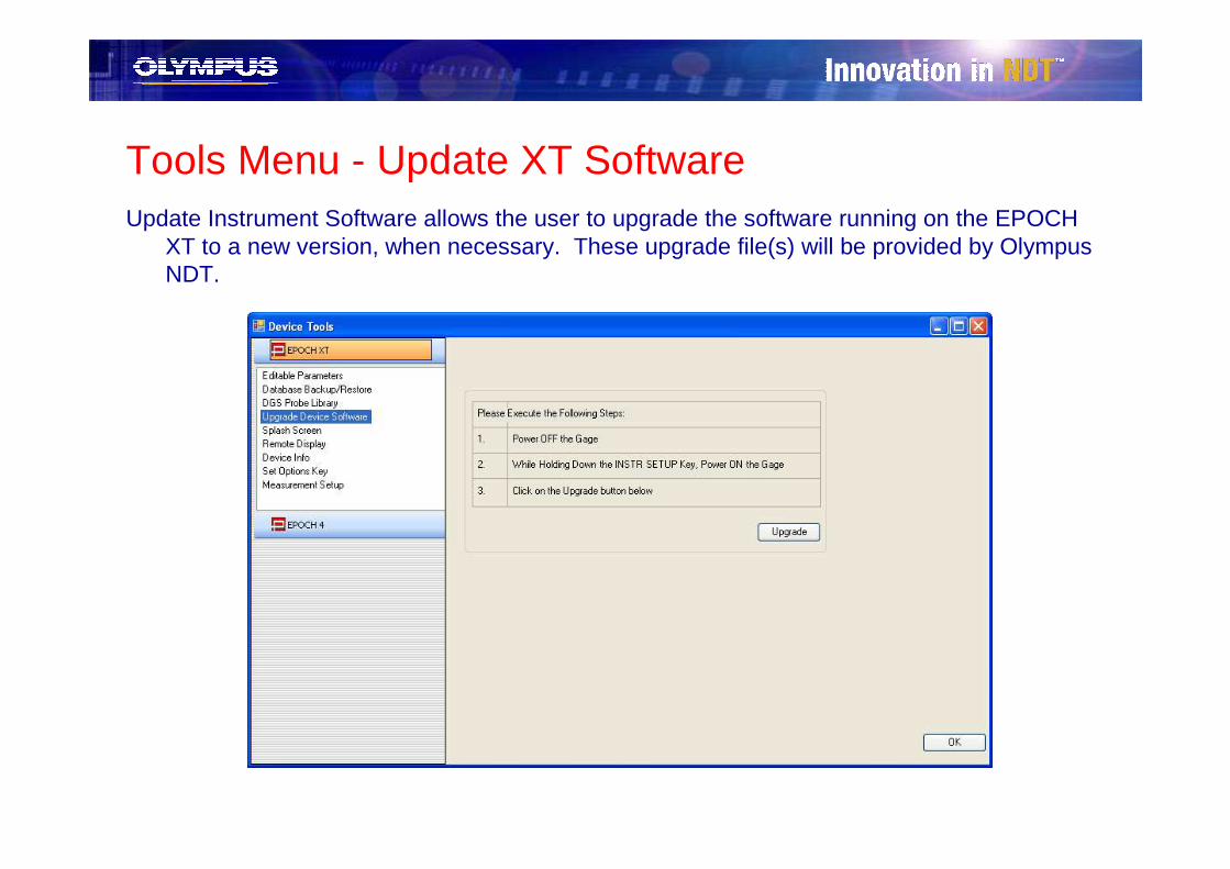
Tools Menu - Update XT SoftwareUpdate Instrument Software allows the user to upgrade the software running on the EPOCH
XT to a new version, when necessary. These upgrade file(s) will be provided by Olympus NDT.
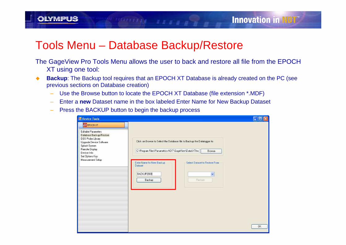
Tools Menu – Database Backup/RestoreThe GageView Pro Tools Menu allows the user to back and restore all file from the EPOCH
XT using one tool:� Backup: The Backup tool requires that an EPOCH XT Database is already created on the PC (see
previous sections on Database creation)– Use the Browse button to locate the EPOCH XT Database (file extension *.MDF)– Enter a new Dataset name in the box labeled Enter Name for New Backup Dataset– Press the BACKUP button to begin the backup process
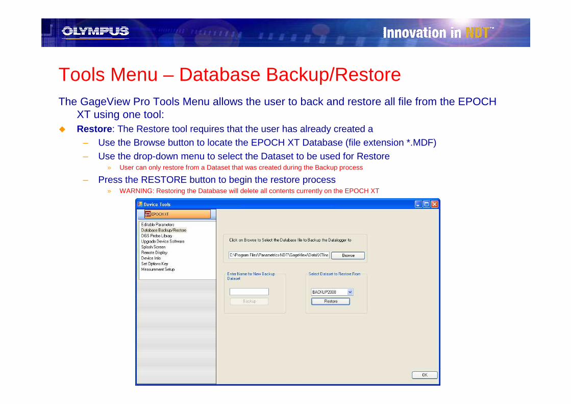
Tools Menu – Database Backup/RestoreThe GageView Pro Tools Menu allows the user to back and restore all file from the EPOCH
XT using one tool:� Restore: The Restore tool requires that the user has already created a
– Use the Browse button to locate the EPOCH XT Database (file extension *.MDF)– Use the drop-down menu to select the Dataset to be used for Restore
» User can only restore from a Dataset that was created during the Backup process
– Press the RESTORE button to begin the restore process» WARNING: Restoring the Database will delete all contents currently on the EPOCH XT

Please contact the Flaw Detector group at Olympus NDT with any questions or comments