g4suws 2009 Jun Jeoandg4
27
Jupiter Europa Orbiter The NASA Element of the Europa Jupiter System Mission Insoo Jun Jet Propulsion Laboratory California Institute of Technology Jupiter Europa Orbiter and Geant4 Copy Right 2009 California Institute of Technology. ACKNOWLEDGEMENT: The research described in this presentation was carried out at the Jet Propulsion Laboratory, California Institute of Technology, under a contract with the National Aeronautics and Space Administration
-
Upload
pedro-leon -
Category
Documents
-
view
13 -
download
2
Transcript of g4suws 2009 Jun Jeoandg4

Jupiter Europa OrbiterThe NASA Element of the Europa Jupiter System Mission
Insoo JunJet Propulsion Laboratory
California Institute of Technology
Jupiter Europa Orbiter and Geant4
Copy Right 2009 California Institute of Technology.
ACKNOWLEDGEMENT: The research described in this presentation was carried out at the Jet Propulsion Laboratory, California Institute of Technology, under a contract with the National Aeronautics and Space
Administration
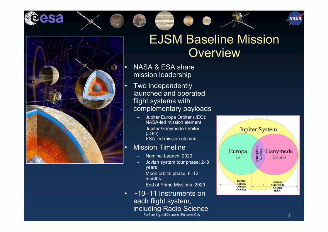
EJSM Baseline Mission Overview
• NASA & ESA share mission leadership
• Two independently launched and operated flight systems with complementary payloads
– Jupiter Europa Orbiter (JEO):NASA-led mission element
– Jupiter Ganymede Orbiter (JGO):ESA-led mission element
• Mission Timeline– Nominal Launch: 2020– Jovian system tour phase: 2–3
years– Moon orbital phase: 6–12
months– End of Prime Missions: 2029
• ~10–11 Instruments on each flight system, including Radio Science
2For Planning and Discussion Purposes Only

JGO Baseline Mission Overview• ESA-led portion of EJSM• Objectives: Jupiter System, Callisto, Ganymede • Launch vehicle: Arianne 5• Power source: Solar Arrays• Mission timeline:
– Launch: 2020• Uses 6-year Venus-Earth-Earth gravity assist trajectory
– Jovian system tour phase: ~28 months• Multiple satellite flybys
– 9 Ganymede– 21 Callisto
– Ganymede orbital phase: 260 days– End of prime mission: 2029– Spacecraft final disposition: Ganymede surface impact
• 10 Instruments, including radio science• Radiation: Current estimated TID for whole mission after 260 days in
Ganymede orbit ~85 krad behind 320 mils of Al (requirement to keep it below 100 krad)
3For Planning and Discussion Purposes Only
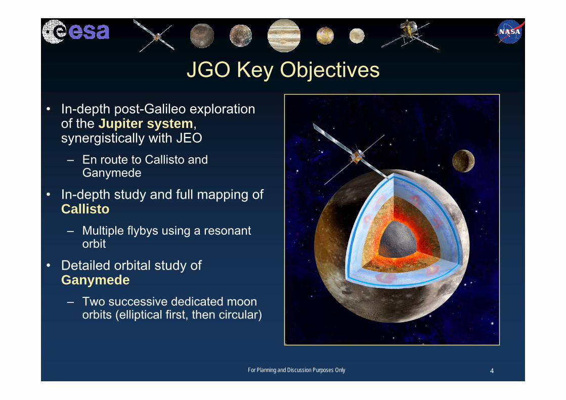
JGO Key Objectives
• In-depth post-Galileo exploration of the Jupiter system, synergistically with JEO – En route to Callisto and
Ganymede
• In-depth study and full mapping of Callisto– Multiple flybys using a resonant
orbit
• Detailed orbital study of Ganymede– Two successive dedicated moon
orbits (elliptical first, then circular)
4For Planning and Discussion Purposes Only

JGO Science HighlightsA major step forward in our understanding of the two “icy” Galilean satellites, Ganymede and Callisto:
• Ocean detection/characterisation• State of internal differentiation• Global surface mapping: morphology and chemistry• Comprehensive study of Ganymede’s magnetism• Relations between thermal history, geology,
oceans and the Laplace resonance
The first global description of the Jovian World as an “integrated system”, together with JEO:
• Jupiter’s atmosphere 3D meteorology and coupling processes,
• Jupiter’s magnetosphere as an “astrophysical object”,
• A major step toward untangling the history of the chemical evolution of the Jupiter system, from formation to potential habitability
5For Planning and Discussion Purposes Only

73 kg core payload:
Wide Angle and Medium Resolution CameraV/NIR Imaging SpectrometerEUV/FUV Imaging SpectrometerKa-band transponderUltra Stable Oscillator Magnetometer Radar SounderMicro Laser Altimeter Thermal IR Mapper Sub-millimeter wave sounder Plasma Package
JGO Reference Model Payload
Imaging
Planetary fields and internal
structure
Atmosphere
Magnetosphere
6For Planning and Discussion Purposes Only

Heritage of Europa Mission Concepts• Europa Orbiter (1997–2001)• Jupiter Icy Moons Orbiter (2002–2005)• Europa Geophysical Explorer (2005) • Europa Explorer (2006)• Europa Explorer (2007)• Jupiter System Observer (2007)• Laplace Cosmic Vision Proposal (2007)• Jupiter Europa Orbiter
– Combines EE 2007, JSO 2007, andEuropa flight element of Laplace
7For Planning and Discussion Purposes Only

JEO Baseline Mission Overview• NASA-led portion of EJSM extensively studied in 2007–2008• Objectives: Jupiter System, Europa • Launch vehicle: Atlas V 551• Power source: 5 MMRTG or 5 ASRG• Mission timeline:
– Launch: 2018 to 2022, nominally 2020• Uses 6-year Venus-Earth-Earth gravity assist trajectory
– Jovian system tour phase: 30 months• Multiple satellite flybys: 4 Io, 6 Ganymede,
6 Europa, and 9 Callisto – Europa orbital phase: 9 months– End of prime mission: 2029– Spacecraft final disposition: Europa surface impact
• 11 Instruments, including radio science• Optimized for science, cost, and risk• Radiation dose: 2.9 Mrad (behind 100 mils of Al)
– Handled using a combination of rad-hard parts and tailored component shielding– Key rad-hard parts are available, with the required heritage– Team is developing and providing design information and approved parts list for
prospective suppliers of components, including instruments8For Planning and Discussion Purposes Only
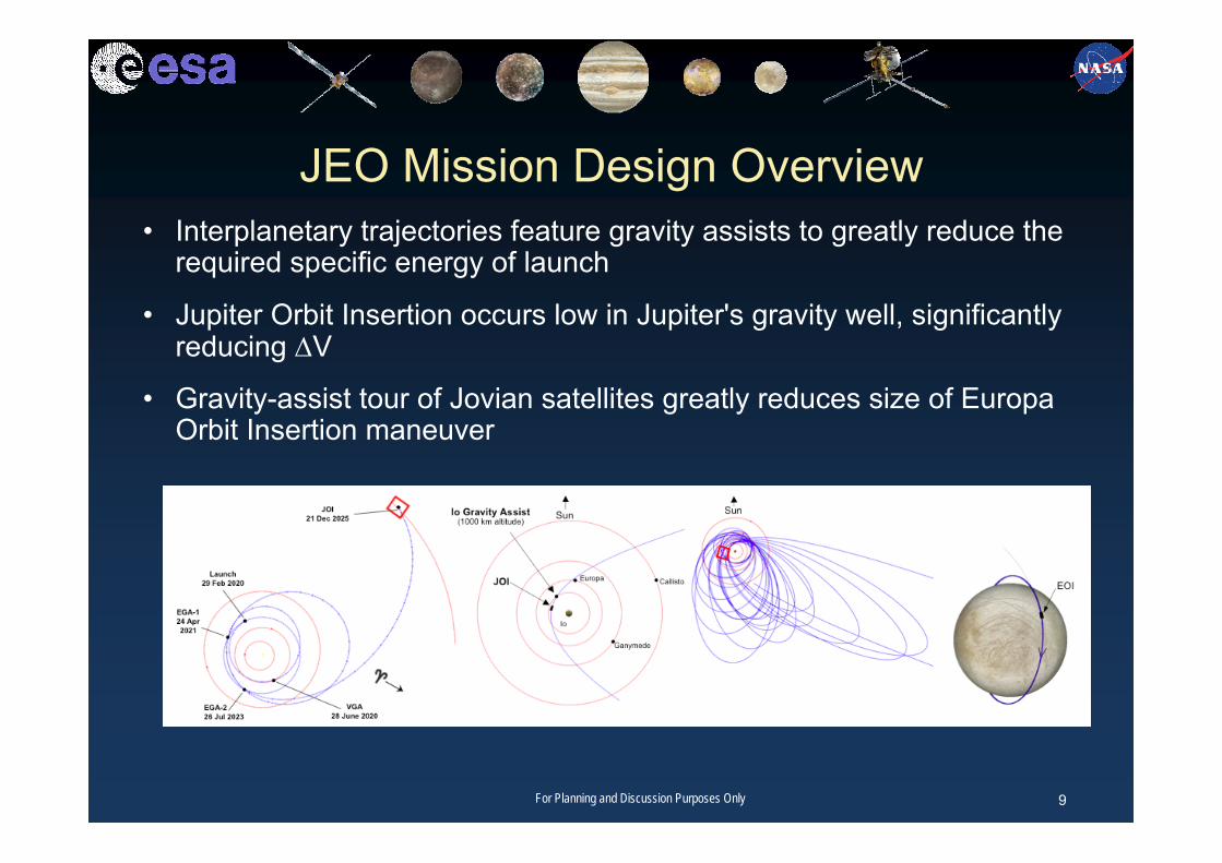
JEO Mission Design Overview• Interplanetary trajectories feature gravity assists to greatly reduce the
required specific energy of launch
• Jupiter Orbit Insertion occurs low in Jupiter's gravity well, significantly reducing ΔV
• Gravity-assist tour of Jovian satellites greatly reduces size of Europa Orbit Insertion maneuver
9For Planning and Discussion Purposes Only

JEO Goal: Explore Europa to Investigate Its Habitability
Objectives:• Ocean and Interior• Ice Shell• Chemistry and Composition• Geology• Jupiter System
– Satellite surfaces and interiors– Satellite atmospheres– Plasma and magnetospheres– Jupiter atmosphere– Rings
Europa is the archetype of icy world habitability 10For Planning and Discussion Purposes Only

JEO Model PayloadJEO Instrument Similar InstrumentsRadio Science New Horizons USO, Cassini KaTLaser Altimeter MESSENGER MLA, NEAR NLRIce Penetrating Radar MRO SHARAD, Mars Express MARSISVIS-IR Spectrometer MRO CRISM, Chandrayaan MMMUV Spectrometer Cassini UVIS, New Horizons AliceIon & Neutral Mass Spectrometer Rosetta ROSINA RTOFThermal Instrument MRO MCS, LRO Diviner Narrow-Angle Camera New Horizons LORRI, LRO LROCCamera Package MRO MARCI, MESSENGER MDISMagnetometer MESSENGER MAG, Galileo MAGParticle and Plasma Instrument New Horizons PEPSSI, Deep Space 1 PEPE
11For Planning and Discussion Purposes Only
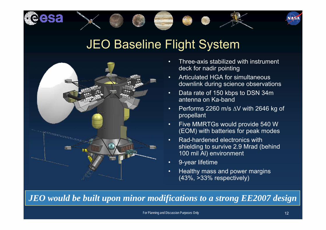
JEO Baseline Flight System• Three-axis stabilized with instrument
deck for nadir pointing• Articulated HGA for simultaneous
downlink during science observations• Data rate of 150 kbps to DSN 34m
antenna on Ka-band• Performs 2260 m/s ∆V with 2646 kg of
propellant• Five MMRTGs would provide 540 W
(EOM) with batteries for peak modes• Rad-hardened electronics with
shielding to survive 2.9 Mrad (behind 100 mil Al) environment
• 9-year lifetime• Healthy mass and power margins
(43%, >33% respectively)
JEO would be built upon minor modifications to a strong EE2007 design12For Planning and Discussion Purposes Only

Power Assembly
Balanced Bus Grounding Hardware
RPS Protection Diodes
Battery Control FET Board
Pyro and Prop Enable Relays
Shunt Limiter FETs
Wheel Drive Electronics (4)
Star Trackers (2)
25 Nms RWA (4) w/ electronics
2-Channel Gimbal Drive Electronics (3)4-Channel Gimbal
Drive Electronics (2)
SIRU (1)
12 A-Hr Li-Ion
Batteries (2)
Lightning Suppression
Assembly
Power Distribution Unit
Power Bus Controller
Power Switch Cards (8)
Power Switch Cards (8)
Power Switch Cards (8)
Power Switch Cards (8)
Power Switch Cards (8)
Power Switch Cards (8)
Power Switch Cards (8)
Power Switch Cards (8)
Prop Drive Electronics (4)
Prop Drive Electronics (4)
Prop Drive Electronics (4)
Prop Drive Electronics (4)
Pyro Driver Cards (6)
Pyro Driver Cards (6)
Pyro Driver Cards (6)
Pyro Driver Cards (6)
Pyro Driver Cards (6)
Pyro Driver Cards (6)
Remote Engineering
Unit (2)
Remote Engineering
Unit (2)
Power Conditioning
Unit (2)
Power Conditioning
Unit (2)
Temp Sensors & Heaters
MLI
Model Payload
C&DH*
Power
Telecom
GHe GHe
Fuel Tank
Gimbaled 890 N HiPATMain Engine
L
16 (8 coupled clusters) 4.5 N ACS Thrusters
Ox Tank
Propulsion
To S/C Loads
U/L, D/L
10m Magnetometer Boom
HGA Gimbal
Variable RHUs (24)
Linear Separation AssemblyLouvers
Main Engine Gimbal
X 4 TWTA
Ka-band
TWTAX-band
25W RF Ka-Band TWTA
(2)
25W RFX-band
TWTA (2)
HYB
X 4
Filter
WTS (2)
WTS
X-Band LGA (2)
3m Ka/X HGA
WTS
HYB
X-Band MGA
WTS
CTS
USO
T
TELECOM ENCLOSURES BEHIND HGA
High-Rate Instruments
IR Spectrometer (VIRIS)
Ice Penetrating Radar (IPR)
Wide Angle & Medium Angle Cameras (WAC + MAC)
Narrow Angle Camera (NAC)
Low-Rate Instruments
Ultraviolet Spectrometer (UVS)
Laser Altimeter (LA)
Ion and Neutral Mass Spectrometer (INMS)
Dual Magnetometer (MAG)
Thermal Instrument (TI)
Particle and Plasma Instrument (PPI)
Shunt Radiator
Computer Chassis (2)cP
CI B
ackp
lane
CEPCU
MTIF
BAE RAD750 (2 slot width)
Custom JEO Card
MREU
Computer Chassis (2)cP
CI B
ackp
lane
MTIF
BAE RAD750 (2 slot width)
Custom JEO Card
MREU
CEPCU
Wheel Drive Electronics (4)Wheel Drive
Electronics (4)Sun Acquisition
Detectors (3)
SDST (2)
X/Ka-bandExciter
X-bandExciter
X-bandReceiver
SDST (2)
X/Ka-bandExciter
X-bandExciter
X-bandReceiver
MMRTG (5)
MMRTG (5)
MMRTG (5)
MMRTG (5)
MMRTG (5)
Waste Heat
Mechanical & Thermal
KaT
Rad Monitoring
Rad Monitoring 6U Electronics Card (Physically
in C&DH Chassis)
3m HGA Boom
Pressure Transducers (10)
DiplexerKa Diplexer (2)
HYB
DiplexerX Diplexer (2)
Sensor 1
Sensor 3
Sensor 2
Hybrid SSR:1Gb CRAM
16 Gb SDRAM Science Memory
JEO Flight System Block Diagram
RHUs (20)
*Note: All C&DH interfaces are cross-strapped.
To MTIF Card in C&DH
Atlas V 551
LV Adapter (LV provides)
T-0 Umbilical
AACS
13For Planning and Discussion Purposes Only
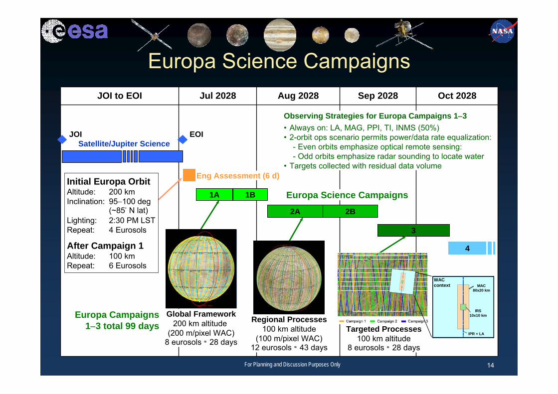
JOI to EOI Jul 2028 Aug 2028 Sep 2028 Oct 2028
Observing Strategies for Europa Campaigns 1−3• Always on: LA, MAG, PPI, TI, INMS (50%)• 2-orbit ops scenario permits power/data rate equalization:
- Even orbits emphasize optical remote sensing:- Odd orbits emphasize radar sounding to locate water
• Targets collected with residual data volume
4
10° x 10°
Eng Assessment (6 d)Initial Europa OrbitAltitude: 200 kmInclination: 95−100 deg
(~85° N lat) Lighting: 2:30 PM LSTRepeat: 4 Eurosols
After Campaign 1Altitude: 100 kmRepeat: 6 Eurosols
3
Targeted Processes100 km altitude
8 eurosols ≈ 28 days
MAC80x20 km
IRS10x10 km
IPR + LA
WAC context
Europa Campaigns 1−3 total 99 days
Europa Science Campaigns
Regional Processes100 km altitude
(100 m/pixel WAC)12 eurosols ≈ 43 days
2A 2B
Global Framework200 km altitude
(200 m/pixel WAC)8 eurosols ≈ 28 days
1A 1B Europa Science Campaigns
EOIJOISatellite/Jupiter Science
14For Planning and Discussion Purposes Only

2008 JEO Design Baseline
Current design practices produce significant marginsand high probability of success through end of mission
• Using traditional methodologies– Current design has an RDF = 7 when JEO begins Endgame– RDF is ~1.25 at end of Prime Mission
A2026 2027 2028
D J F M A M J J A S O N D J F M A M J J A S O N D J F M A M J J A S O N D
JOI EOI
Ganymede Encounters
Callisto Encounters
Europa Encounters
Io Encounters
End of Prime Mission
Europa Science
J F M
Estimated Mean Total Ionizing Dose (TID)
2029Jovian Tour
2.9 Mrads (Si)(Design Point)
System Survival
99%
80%
Rad
iatio
n D
esig
n Fa
ctor
Rad
iatio
n D
ose
(Mra
d)
15For Planning and Discussion Purposes Only

System Design Process
Input Variables
• Science Objectives
• Mission Design—Environment
• Launch Vehicle Capabilities
• Part Capabilities
Dependent Components• Shielding Design• Instrument and Circuit Design• Margin Assessment• Risk Analysis• Cost Analysis
Iteration• System design iterative process continues through Phase B as capabilities
evolve and science instrument capabilities solidify• Acceptable cost and risk posture is a joint discussion between project and
NASA Headquarters
Analysis
16For Planning and Discussion Purposes Only

Mission Design—Environment• The JEO mission design takes advantages of better radiation
knowledge than available for Galileo design– The JEO dose-depth curve is similar to that of Galileo at end of its
mission (J35)– Environment is modeled statistically based primarily on Galileo data– The JEO peak flux is comparable to or lower than that of Juno– Data available from Juno will be incorporated when available
• Io flyby strategy is a better engineering solution than the Ganymede strategy used in 2007 Europa Explorer Mission Study– ΔV savings of 200 m/s at first-flyby altitude of 1000 km– Tour strategy involves ~0.4 Mrad increase– A net dry-mass increase to Europa orbit of approximately 100 kg
17For Planning and Discussion Purposes Only

JEO vs. GLL vs. Juno Mean Dose-Depth Curves
1.E+03
1.E+04
1.E+05
1.E+06
1.E+07
1.E+08
10 100 1000 10000aluminum shield thickness, mil
rad(
Si)
JEO 2008 Reference
GLL
Juno
End of Mission (J35)
Mission Duration : 14 months
Mission Duration : 39 months
The estimated TID radiation design environment for JEO is similar tothe estimated end-of-mission Galileo environment
18For Planning and Discussion Purposes Only

Peak Flux Comparison: JEO vs. Juno
The radiation flux design environment for JEO is less than that for Juno
19For Planning and Discussion Purposes Only

Detector Radiation Effects Analysis• A Detector Working Group (DWG) comprised of experienced detector,
instrument, and radiation experts from JPL and APL was formed to evaluate the radiation tolerance of existing detector technologies
• The DWG also assessed the response of detectors to incident electron and proton radiation to determine the impact on science measurement quality
• Silicon used by NAC, MAC, WAC• HgCdTe (MCT) used by VIRIS• Microchannel plate (MCP) used by PPI, INMS, UVS• Avalanche photodiode (APD) used by LA
– The incident radiation flux reaching the detector through various levels of radiation shielding, with the response of the detector to that radiation flux, was used to determine the amount of radiation shielding required for acceptable science measurement quality
• The DWG found that detector radiation shielding requirements are driven by electron-induced transient noise, not total dose
– Shielding to mitigate transient noise effectively mitigates total-dose effects
Existing detectors, shielded to mitigate background radiation noise,meet JEO mission dose and science measurement requirements
20For Planning and Discussion Purposes Only

2008 JEO Detector Working Group
Insoo Jun For Planning and Discussion Purposes Only 21
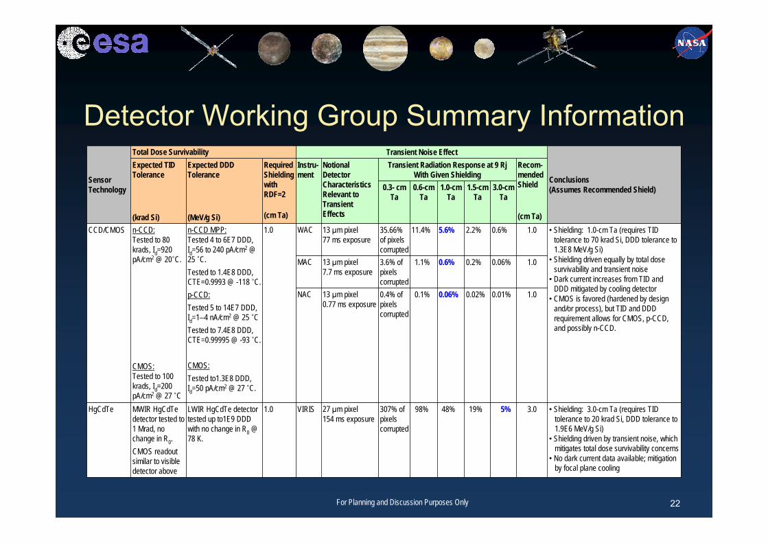
Detector Working Group Summary Information
Sensor Technology
Total Dose Survivability Transient Noise Effect
Conclusions (Assumes Recommended Shield)
Expected TID Tolerance
(krad Si)
Expected DDD Tolerance
(MeV/g Si)
Required Shielding with RDF=2
(cm Ta)
Instru-ment
Notional Detector Characteristics Relevant to Transient Effects
Transient Radiation Response at 9 Rj With Given Shielding
Recom-mended Shield
(cm Ta)
0.3- cm Ta
0.6-cm Ta
1.0-cm Ta
1.5-cm Ta
3.0-cm Ta
CCD/CMOS n-CCD:Tested to 80 krads, Id=920 pA/cm2 @ 20˚C.
CMOS:Tested to 100 krads, Id=200 pA/cm2 @ 27 ˚C
n-CCD MPP: Tested 4 to 6E7 DDD, Id=56 to 240 pA/cm2 @ 25 ˚C. Tested to 1.4E8 DDD, CTE=0.9993 @ -118 ˚C. p-CCD: Tested 5 to 14E7 DDD, Id=1–4 nA/cm2 @ 25 ˚C Tested to 7.4E8 DDD, CTE=0.99995 @ -93 ˚C.
CMOS:Tested to1.3E8 DDD, Id=50 pA/cm2 @ 27 ˚C.
1.0 WAC 13 µm pixel77 ms exposure
35.66% of pixels corrupted
11.4% 5.6% 2.2% 0.6% 1.0 • Shielding: 1.0-cm Ta (requires TID tolerance to 70 krad Si, DDD tolerance to 1.3E8 MeV/g Si)
• Shielding driven equally by total dose survivability and transient noise
• Dark current increases from TID and DDD mitigated by cooling detector
• CMOS is favored (hardened by design and/or process), but TID and DDD requirement allows for CMOS, p-CCD, and possibly n-CCD.
MAC 13 µm pixel7.7 ms exposure
3.6% of pixels corrupted
1.1% 0.6% 0.2% 0.06% 1.0
NAC 13 µm pixel0.77 ms exposure
0.4% of pixels corrupted
0.1% 0.06% 0.02% 0.01% 1.0
HgCdTe MWIR HgCdTe detector tested to 1 Mrad, no change in R0. CMOS readout similar to visible detector above
LWIR HgCdTe detector tested up to1E9 DDD with no change in R0 @ 78 K.
1.0 VIRIS 27 µm pixel154 ms exposure
307% of pixels corrupted
98% 48% 19% 5% 3.0 • Shielding: 3.0-cm Ta (requires TID tolerance to 20 krad Si, DDD tolerance to 1.9E6 MeV/g Si)
• Shielding driven by transient noise, which mitigates total dose survivability concerns
• No dark current data available; mitigation by focal plane cooling
22For Planning and Discussion Purposes Only

Parts CapabilitiesRadiation Requirements Comparison
JEO parts requirements are similar to MEO Military Satellites, though shielding limitations and planetary protection pose significant challenges
Aspect Military GEO* Military MEO* JEO
Mission Duration 15 yr 6 to 10 yr 9 yr
Parts TID Capability <100 krad 100 to 300 krad 300 krad desired
Mission Dose 500 krad@100 mil Al
800 krad@100 mil Al
2.9 Mrad@100 mil Al
Shielding Effectiveness Down to <10 krad Down to ~20 krad <100 krad
very massive
DD Dose Up to 6x10¹¹ eq.N/cm2 >2x10¹² eq. N/cm2 2x10¹² eq. N/cm2
Planetary Protection No Requirement No Requirement Required
* GEO: Geostationary Earth Orbit; MEO: Medium Earth Orbit
23For Planning and Discussion Purposes Only

Geant4 for JEO• Simulation of signal to noise ratios in sensors and
detectors in high energy electron environment
• Computation of response function (e.g., geometric factor) for particle detectors
• Shielding analysis– Material selection criteria (e.g., low-Z, high-Z, or combination of
them
• Particle trajectory analysis in the Jovian magnetosphere (or in the vicinity of Europa)
Insoo Jun For Planning and Discussion Purposes Only 24

Example: Model Layers for Transient Estimates
• 5 Layers in GEANT4
• Detector Array with 7 elements– Cylindrical Geometry Assumed– Initial results similar to results in
Pickel’s 2005 NSREC paper
• Semi-infinite shielding slabs
• Shield Material– WCu, Al, Ta– Thickness ∼ 1.6, 8 and 16g/cm2
• Ceramic and Cu layers used to account for backscatter
Shield Material
D D D D D D D
Alumina Backing
Copper Layer
Shield Material
Initial BeamElectron beam (mono-energetic)
Courtesy of D. Roth (APL)

Example: Geant4 Simulation of Shields• One dimensional analysis to define the shield thickness of
a dosimeter “channel”. – For example, we’d like to obtain the shield thickness, behind which
a “RadFET” will predominantly measure >10 MeV electrons.
26
100k electronsincident
Courtesy of D. Haggerty (APL)

Summary• An overview of Jupiter Europa Orbiter is presented.
• The challenges associated with harsh radiation environment were discussed.– Mission fluence– Peak flux
• It is emphasized that detector survivability (or operability) in this environment is a key for the mission success.– Early identification of the problems through analyses and tests is
important.– Geant4 can be very useful for this purpose with its comprehensive
physics packages and modeling capabilities.– Geant4 will be one of the tools that the Project plans to use heavily
in the detector modeling effort.Insoo Jun For Planning and Discussion Purposes Only 27