G110D - Suzuki Perúsuzuki.com.pe/motos/wp-content/uploads/2016/12/GD110HUL0_99500H23131H... ·...
130
G 110 D 99500H23131H000 SERVICE MANUAL SERVICE MANUAL
Transcript of G110D - Suzuki Perúsuzuki.com.pe/motos/wp-content/uploads/2016/12/GD110HUL0_99500H23131H... ·...
G 110D
99500H23131H000
SERVICE MANUALSERVICE MANUAL
GD110

GROUPINDEX
GENERAL INFORMATION
PERIODIC MAINTENANCE ANDTUNE-UP PROCEDURES
ENGINE
ELECTRICAL SYSTEM
CHASSIS
SERVICING INFORMATION
FOREWORD
JIANGMEN DACHANGJIANG GROUP CO., LTD.
JUNE 2010
(The First Edition)
FUEL AND LUBRICATIONSYSTEM
1
2
3
4
5
6
7
8
This Service Manual is mainly prepared for the
distributors and maintenance technicians of Haojue
motorcycles for the convenience of the repair and
maintenance of GD110 motorcycles. This Service
Manual excludes the general repair knowledge of
motorcycles, so it is suitable for the people who have
known the basic repair knowledge of Haojue
motorcycles and can offer helpful references for
repair of the motorcycles of similar models.
All materials, illustrations, pictures and parameters
collected in this Service Manual are the latest when it
is published. However, the motorcycles reaching you
may differ slightly with the content herein due to the
continuous improvement and technical upgrade of
products. Our company will promptly inform the
distributors of Haojue motorcycles about this. If
necessary, you may consult with them directly.
We shal l have the r ight to conduct product
improvement at any time without prior notice and will
assume no responsibilities about this.
No reproduction of any contents of this Service
Manual without permission.

SYMBOLThe following symbols are instructions and necessary information for maintenance.
SYMBOL
OIL
Note:All symbols are shown in the table above, including those not used in this Service Manual.
SYMBOLDEFINITION DEFINITION
No.4
APPLY SUPER SILICONE GREASE
APPLY SUPER GREASE “A”
APPLY MOLY PASTE
Apply BOND No.4
APPLY THREAD LOCK “1322”
APPLY THREAD LOCK SUPER “1342”
APPLY SUPER GREASE “C” APPLY THREAD LOCK SUPER “1360”
APPLY THREAD LOCK SUPER “1303”
APPLY HEAT TRANSFER OIL
APPLY SEALANT THREE
BOND “1215”
APPLY SEALANT THREE
BOND “1216”
APPLY SEALANT THREE
BOND “1207B”
APPLY OR USE COOLANT
APPLY MOLYBDENUM OIL SOLUTION.
Mix engine oil and MOLY PASTE at a
ratio of 1:1.
APPLY oil. Use engine oil unless
otherwise specified.
Torque control required.
Data beside it indicates specified
torque.
APPLY OR USE BREAK FLUID
MEASURE IN VOLTAGE RANGE
MEASURE IN RESISTANCE RANGE
MEASURE IN CURRENT RANGE.
MEASURE THE TESTING RANGE OF
THE DIODE
MEASURE THE BREAK OVER RANGE
USE SPECIAL TOOL
It refers to the date of
maintenance.
APPLY OR USE FRONT DAMPER OIL

1
CONTENTS
1
1-1
1-1
1-2
1-3
1-3
1-4
GENERAL INFORMATION
WARNING/CAUTION/NOTICE/NOTE
GENERAL PRECAUTIONS
SERIAL NUMBER LOCATIONS
FUEL AND OIL RECOMMENDATIONS
BREAK-IN PROCEDURE
SPECIFICATIONS

WARNING
CAUTION
1-1
WARNING/CAUTION/NOTICE/NOTE
Please read this manual and follow its instructions carefully. Toemphasize special information, the symbol
and the words WARNING, CAUTION, NOTICE AND NOTE have special meanings.Pay particular
attention to messages highlighted by these signal words:
NOTICE
Indicates a potential hazard that could result in death or serious injury.
Indicates a potential hazard that could result in minor or moderade injury.
Indicates a potential hazard that could result in vehicle or equipment damage.
NOTE:
Indicates special information to make maintenance easier or instructions clearer.
Please note, however, that the warnings and cautions contained in this manual cannot possibly cover all
potential hazards relating to the servicing, or lack of servicing, of the motorcycle. In addition to the
WARNINGS and CAUTIONS stated, you must use good judgment and basic mechanical safety principles.
If you are unsure about how to perform a particular service operation, ask a more experienced mechanic
for advice.
GENERAL PRECAUTIONS
WARNING
● Proper service and repair procedures are important for the safety of the service mechanic and
thesafety and reliability of the vehicle.
When 2 or more persons work together, pay attention to safety of each other.
When it is necessary to run the engine indoors, make sure that exhaust gas is forced outdoor.
When working with toxic or flammable materials, make sure that the area you work in is well-
ventilated and that you follow all off the material manufacturer's instructions.
Never use gasoline as a cleaning solvent.
To avoid getting burned, do not touch the engine, engine oil or exhaust system during or for a
while after engine operation.
After servicing fuel, oil, exhaust or brake system, check all lines and fittings related to the
system for leaks.
●
●
●
●
●
●
GENERAL INFORMATION

1-2
●
.
If parts replacement is necessary, replace the parts with HAOJUE GENUINE PARTS or their equivalent.
When removing parts that are to be reused, keep them arranged in an orderly manner so that they may
be reinstalled in the proper order and orientation
Be sure to use special tools when instructed.
Make sure that all parts used in reassembly are clean, and also lubricated when specified.
When use of a certain type of lubricant, bond, or sealant is specified, be sure to use the specified type.
When performing service to electrical parts, if the service procedures not require used of battery power,
disconnect the positive terminal.
When removing the battery, disconnect the negative cable first and then the positive cable.
When reconnecting the battery, connect the positive cable first and then the negative cable, and
replace the terminal cover on the positive terminal.
Tighten cylinder head and case bolts and nuts, beginning with larger diameter and ending with smaller
diameter, from inside to outside diagonally, to the specified tightening torque.
Whenever you remove oil seals, gaskets, packing, O-rings, locking washers, cotter pins, circlips, and
certain other parts as specified, be sure to replace them with new ones. Also, before installing these
new parts, be sure to remove any left over material from the mating surfaces.
Never reuse a circlip. When installing a new circlip, take care not to expend the end gap larger than
required to slip the circlip over the shaft. After installing a circlip, always ensure that it is completely
seated in its groove and securely fitted.
Do not use self-locking nuts a few times over.
Use a torque wrench to tighten fasteners to the torque values when specified. Wipe off grease or oil if a
thread is smeared with them.
After reassembly, check parts for tightness and operation.
●
●
●
●
●
●
●
●
●
●
●
●
●
NOTICE
NOTE:
●
●
To protect environment, do not unlawfully dispose of used motor oil and other fluids, batteries and tires.
To protect Earth's natural resources, properly dispose of used vehicles and parts.
SERIAL NUMBER LOCATIONSThe frame serial number is stamped on on the steering stem. The engine serial number is located on
the right side of the crankcase.
These numbers are required especially for registering the machine and ordering spare parts.
① ②
2
1
GENERAL INFORMATION

1-3
FUEL AND OIL RECOMMENDATION
FUELUse nonleaded gasoline with a rating of 90-97.
ENGINE OILOil quality is a major contributor to your engine’s performance and
life. Always select good quality engine oil. Use oil with an API
classi-fication of SF/SG or SH/SJ, or with JASO classification of
MA.
BREAK-IN PROCEDURES
During manufacture only the possible materials are used and
all machined parts are finished to a very high standard but it is
still necessary to allow the moving parts to “BREAK-IN” before
subjecting the engine to maximum stresses. The future
performance and reliability of the engine depends on the care
and restraint exercised during its early life. The general rules
are as follows.
●
●
The break-in mileage is 500 km.
The throttle must not be opened to the full during the new
motorcycle's break-in period. Throttle opening should be
limited to 3/4 of its maximum, while snap-acceleration
should be avoided.
≦
GENERAL INFORMATION
NOTE:
Using nonleaded can extend the life of spark plug.gasoline
NOTE:
Dispose used engine oil to avoid environment pollution. We
suggest you to collect the used oil in a sealed container and take it to
a nearby recycling facility.
Do not place it into a trash bin and do not pour it onto the ground.
properly
ENGINE OIL
TEMP.
SF/SG
SAE
SH/SJ
API
10W-40
JASO
-
10W-40 MA
API :American Petroleum Institute
JASO: Japanese Automobile Standards Organization
SAE ENGINE OIL VISCOSITYSuzuki recommends the use of SAE 10W-40 engine oil. If SAE 10W-
40 engine oil is not available, select an alternative according to the
following chart.

1900
750
050
15
40
08
mm
mm
1 mm
12 mm
1 mm
1 kg
four-stroke, air-cooled, Single-cylinder vertical type
1
51mm
55.2mm
112.8ml
9.5:1
Vacuum diaphragm type
Polyurethane foam and paper filter
Kick starting
Pressure splash lubrication
Wet multi-plate
4-speed gear transmission
3.666
500
3.000
923
375
052
0 Nodes
2.
1.
1.
1.
428H,1 4
1-4
GENERAL INFORMATION
SPECIFICATIONS
DIMENSIONS AND CURB WEIGHT
Overall length
Overall width
Overall height
Wheelbase
Ground clearance
Curb weight
ENGINE
Type
Number of cylinders
Bore
Stroke
Piston displacement
Compression ratio
Carburetor
Air cleaner
Starter system
Lubrication system
TRANSMISSION
Clutch
Transmission
Primary reduction
Final reduction
Gear ratios, low
2nd
3rd
4th
Drive chain

DC-
15°B.T.D.C. Below 1500r/min and
35°B.T.D.C. above 4000r/min
NGK CR6HSA
5
5
12V,2W
12V,2W
CDI
12V Ah
15A
12V,35W/35W
12V,5W/21W
12V,10W
12V, W
12V,3W
12V,2W
12V,2W
Telescopic, coil spring, oil dampened
Swing arm, oil dampened
spring 5-way adjustable
1840m
Drum
Drum
50 7 38L
2.75-17 41P
00
m
2. -1
1 mm
9.2
1.8
1 100
06
L
L
mL
1 mL
1-5
GENERAL INFORMATION
ELECTRICAL
Ignition type
Ignition timing
Spark plug
Battery
Fuse
Headlight
Tail/Brake light
Turn signal light
Position light
Speedometer light
Gear position indicator light
Gear indicator
High beam indicator light
Turn signal indicator light
light
Fuel tank including reserve
Engine oil
Front shock absorber oil
reserve
CHASSIS
Front suspension
Rear suspension
Turning radius
Front brake
Rear brake
Front tire size
Rear tire size
Stroke of front absorber
CAPACITIES

2
2-1
2-3
2-3
2-4
2-5
2-5
2-6
2-7
2-7
2-8
2-8
2-8
2-8
2-9
2-9
2-9
2-10
2-10
2-12
2-13
2-13
2-13
2-14
2-16
PERIODIC MAINTENANCE
CONTENTS
PERIODIC MAINTENANCE
MAINTENANCE PROCEDURES
BATTERY/
VALVE CLEARANCE
SPARK PLUG
FUEL FILTER
DRIVE CHAIN
BRAKES
TIRES
STEERING
FRONT/REAR SUSPENSION
CHASSIS AND ENGINE MOUNTING BOLTS AND NUTS
COMPRESSION PRESSURE INSPECTION
TUBE FUSE (FUSE)
BOLTS/NUTS OF THE CYLINDER HEAD & CYLINDER
THROTTLE CABLE PLAY
ILLUMINATION AND SIGNAL
AIR CLEANER ELEMENT
ENGINE OIL
ENGINE OIL FILTER
OIL SUMP FILTER
CLUTCH CABLE
CARBURETOR ( )
FUEL HOSE AND
MUFFLER BOLTS AND NUTS
IDLE SPEED
2ND AIR HOSE

2-3
2-5
2-9
2-8
2-4
2-7
2-6
2-5
2-1
2-8
2-8
2-9
2-9
2-14
2-10
2-10
2-12
2-13
2-13
2-13
2-5
2-16
2-7
PERIODIC MAINTENANCEThe chart below lists recommended intervals for all the required periodic service work necessary to keep
the motorcycle operating at peak performance and economy. Mileages are expressed in terms of
kilometer, miles and time for your convenience.
NOTE:
More frequent servicing may be performed on motorcycles that are used under severe conditions.
PERIODIC MAINTENANCE CHART
PERIODIC MAINTENANCE
INTERVAL
ITEM month
1000 3000 6000
3 6 12PAGE
Replace every four years
Initial replacement after the first 500 km, the second replace-ment at 1,000km total mileage, while further replacement forevery 2,000-3,000 km (adjust according to driving conditions)
Clean every 12000 km
Clean & lubricate for every 1,000 km
Inspect Inspect
Clean after the first 1,000 km and every 2,000-3,000 km afterwards
Inspect Inspect
Inspect Inspect
Inspect Inspect
Inspect Inspect
Replace Replace
Inspect Inspect
Inspect Inspect
Inspect Inspect
Inspect Inspect
Inspect Inspect
Inspect Inspect
Inspect Inspect
Inspect
InspectInspect
Inspect
InspectInspect
Inspect Inspect
Replace every 10 000 km
Battery/tube fuse (fuse)
Air filter (filter element)
Muffler bolts and nuts
Bolts and nuts of cylinder
head and cylinder
Valve clearance (cold engine)
Spark plug
Engine oil
Engine oil filter
Oil sump filter
Clutch cable
Carburetor (idle speed)
Throttle cable play
Fuel hose and 2nd air hose
Fuel filter
Drive chain
Brake
Tires
Steering
Front and rear suspension
Illumination and signal
Chassis and engine
mounting bolts and nuts
Compression pressure
Km

2-2
_
_
_
_
_
_
12
LUBRICATION CHART
The following is a basic lubrication requirement for a motorcycle operated in an economical manner and
based on the mileage displayed by the odometer.
INTERVAL
ITEM
km
month
Initial and every 5000 km Every 10000 km
6
Motor oil
Grease
Motor oil every 1000 km
Grease or oil
Grease every 2 years or 20000 km
Grease
Grease
Grease
NOTE:
“-"stands for not required
Do not apply too much lubrication grease on the brake cam to prevent the brake from slipping.
WARNING
Throttle cable
Throttle grip
Clutch cable
Brake cable
Soft axle for
Gear box for speedometer
Transmission Chain
Brake pedal axle
Brake camshaft
Steering bearing
Bearing bush for rear rocker arm
speedometer
When driving on wet roads or under rainy conditions, lubricate the parts with engine oil or grease to avoid
rust. Be sure to remove oily contamination or rust.
PERIODIC MAINTENANCE
Motor oil
Motor oil
_
_

1.28 0.01 20℃
2-3
2
09900-28403 : HYDROMETER
Breatherpipe
Battery
1
PERIODIC MAINTENANCE
MAINTENANCE PROCEDURES
BATTERY/TUBE FUSE (FUSE)
Inspect Initial 1 000 km and Every 3 000 km
When assemble the battery, fix the “+” positive pole firstand the “-” negative pole then.
This section introduces the maintenance and adjustment
methods of each part during regular maintenance.
BATTERY
Inspect the electrolyte's level and specific gravity, the
battery must be removed.
Dismount the right cover.
Dismount the “-” negative pole of the battery.
Dismount the “+” positive pole of the battery.
Dismount the band of the battery.
Take the battery down from the battery holder.
Inspect the electrolyte level. If necessary, add some
distilled water to make the electrolyte level higher than the
“LOWER LEVERL” and lower than the “UPPER
LEVERL” . Use a hydrometer to inspect the electrolyte's
specific gravity to see the charging situation of the battery.
If the data is below 1.28 (20 ), it means that the battery
should be charged now. During charge, the battery should
be dismounted and charged with a charger. If not, the
rectifier may be damaged.
①②
℃
●
●
●
●
●
●
●
Standard specific gravity
Assemble the battery in the opposite order of the
disassembly.
●
NOTICE
TUBE FUSE (FUSE)
The tube fuse (fuse) box locates on the band of the battery.
In case of engine stop suddenly or the circuit non-through,
the tube fuse (fuse) must be inspected.
●
WARNING
Do not use fuses without the specified specification;otherwise it will have ill effect on the electric system,or even result in fire, burn the motorcycle or loss powerof the engine, which is very dangerous.
NOTICE
Do use the tube fuse (fuse) with the specified ratedcurrent (15A) and do not use substitutes like aluminumfoil, iron wire and so on. In case of fusing, it suggeststhat the electric system has malfunction and should beinspected.

2-4
PERIODIC MAINTENANCE
AIR CLEANER ELEMENT
Clean after the first 1,000 km and every 2,000-3,000 kmafterwards
If the air cleaner is clogged with dust, intake resistance will be
increased with a resultant decrease in power output and an
increase in fuel consumption.
The air filter should be inspected and cleaned according to the
following order:
Take off the left cover.
Unscrew the bolts from the cover and take off the cover.
Take out the straining sponge.
●
●
●
Unscrew the fastening screw of the air filter and take off the
air filter.
●
Blow the dust on the air filter with an air hose.●
NOTE:
Blowing air should be from the interior of the air filter, otherwise
the dust will be blown into the pores of the air filter, and block
the air filter.
If paper filter is damaged or the filtration pores have become
bigger, the air filter should be replaced.
Assemble the cleaned air cleaner or a new one in reverse
order of disassembly.
●
When riding in a dusty environment, should replace the
air cleaner more frequently to avoid premature abrasion
of the engine.
NOTICE

2-5
3
1
2
4
PERIODIC MAINTENANCE
MUFFLER BOLTS AND NUTS
Inspect Initial 1 000 km and Every 3 000 km
Tighten the muffler bolts and with the specified
torque.
① ②●
Muffler bolt 20~24N m① :Muffler bolt 40~45N m② :
BOLTS/NUTS OF THE CYLINDER HEAD &CYLINDER
Inspect Initial 1 000 km and Every 3 000 km
NUTS OF THE CYLINDER HEAD
Take off the seat and the fuel tank (see content on page 3-2).
Tighten the four M10 nuts with the specified torque
through a torque wrench under cool engine conditions.
③
●
●
Nuts on the cylinder head 23~27N m:
BOLTS OF THE CYLINDER
Tighten the bolts on side of the cylinder head with the
specified torque.
④●
Bolts on the cylinder 8~12N m:
VALVE CLEARANCE
Inspect Initial 1 000 km and Every 3 000 km
Too big valve clearance will result in valve noise; and too
small valve clearance will lead to valve damage and power
output decrease. The valve clearance should be inspected at
the mileages mentioned above, and adjusted by following
order.
Remove spark plug, valve timing inspection plug and
inlet/exhaust valve plug.
Unscrew the plug of the generator cover, and rotate the
generator rotor anticlockwise with a box wrench till the “T”
scribed line on the generator rotor aligns with the center
(the position pointed by the arrow) of the valve timing
inspection plug hole on the crankcase, to set the piston at
TDC of compression stroke.
Insert the thickness gauge of the standard specification
into the space between the valve end and the adjusting
screw of the rocker arm.
●
●
●
09900-20803 Thickness gauge:
0.03-0.08mm
0.08-0.13mm
●
2-6
11F14-016 : Adjustment wrench
0.6-0.7mm
PERIODIC MAINTENANCE
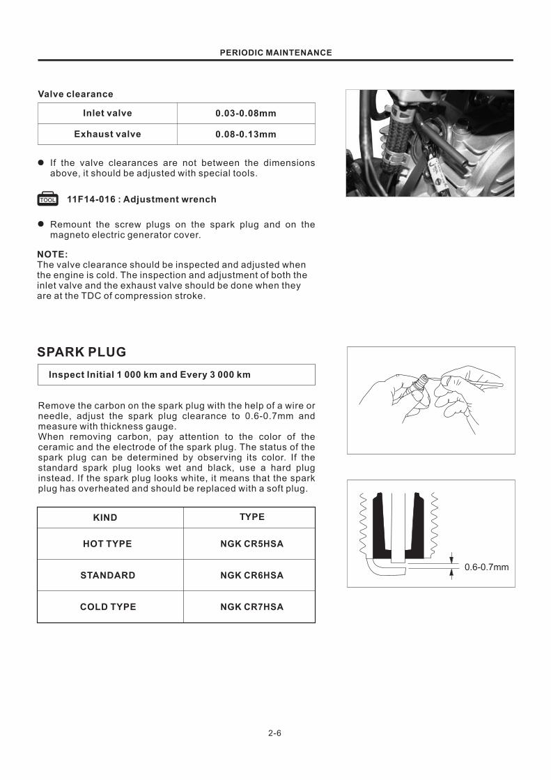
Valve clearance
Inlet valve
Exhaust valve
If the valve clearances are not between the dimensions
above, it should be adjusted with special tools.
Remount the screw plugs on the spark plug and on the
magneto electric generator cover.
●
NOTE:The valve clearance should be inspected and adjusted when
the engine is cold. The inspection and adjustment of both the
inlet valve and the exhaust valve should be done when they
are at the TDC of compression stroke.
SPARK PLUG
Inspect Initial 1 000 km and Every 3 000 km
Remove the carbon on the spark plug with the help of a wire or
needle, adjust the spark plug clearance to 0.6-0.7mm and
measure with thickness gauge.
When removing carbon, pay attention to the color of the
ceramic and the electrode of the spark plug. The status of the
spark plug can be determined by observing its color. If the
standard spark plug looks wet and black, use a hard plug
instead. If the spark plug looks white, it means that the spark
plug has overheated and should be replaced with a soft plug.
TYPEKIND
STANDARD
COLD TYPE
HOT TYPE NGK CR5HSA
NGK CR6HSA
NGK CR7HSA
2-7
2
1
3
2
1
PERIODIC MAINTENANCE
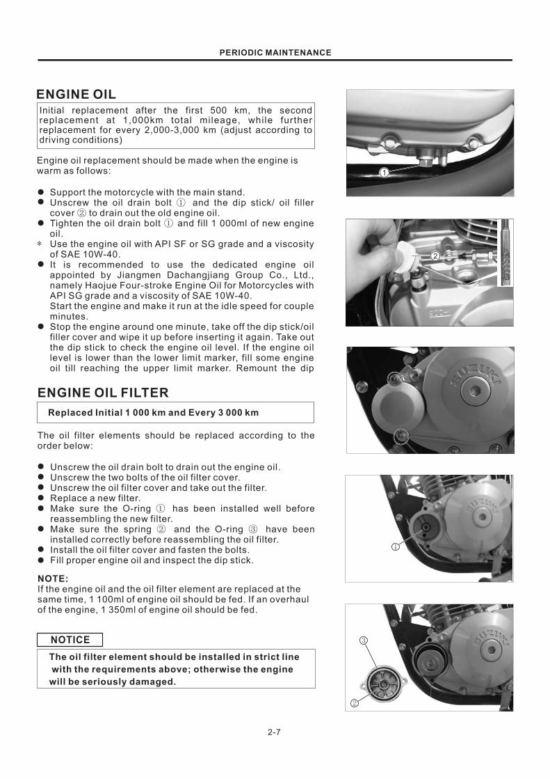
ENGINE OILInitial replacement after the first 500 km, the second
replacement at 1,000km total mileage, while further
replacement for every 2,000-3,000 km (adjust according to
driving conditions)
Engine oil replacement should be made when the engine is
warm as follows:
Support the motorcycle with the main stand.
Unscrew the oil drain bolt and the dip stick/ oil filler
cover to drain out the old engine oil.
Tighten the oil drain bolt and fill 1 000ml of new engine
oil.
Use the engine oil with API SF or SG grade and a viscosity
of SAE 10W-40.
It is recommended to use the dedicated engine oil
appointed by Jiangmen Dachangjiang Group Co., Ltd.,
namely Haojue Four-stroke Engine Oil for Motorcycles with
API SG grade and a viscosity of SAE 10W-40.
Start the engine and make it run at the idle speed for couple
minutes.
Stop the engine around one minute, take off the dip stick/oil
filler cover and wipe it up before inserting it again. Take out
the dip stick to check the engine oil level. If the engine oil
level is lower than the lower limit marker, fill some engine
oil till reaching the upper limit marker. Remount the dip
①②
①
●
●
●
●
●
*
ENGINE OIL FILTER
Replaced Initial 1 000 km and Every 3 000 km
The oil filter elements should be replaced according to the
order below:
Unscrew the oil drain bolt to drain out the engine oil.
Unscrew the two bolts of the oil filter cover.
Unscrew the oil filter cover and take out the filter.
Replace a new filter.
Make sure the O-ring has been installed well before
reassembling the new filter.
Make sure the spring and the O-ring have been
installed correctly before reassembling the oil filter.
Install the oil filter cover and fasten the bolts.
Fill proper engine oil and inspect the dip stick.
①
② ③
●
●
●
●
●
●
●
●
NOTE:If the engine oil and the oil filter element are replaced at the
same time, 1 100ml of engine oil should be fed. If an overhaul
of the engine, 1 350ml of engine oil should be fed.
The oil filter element should be installed in strict line
with the requirements above; otherwise the engine
will be seriously damaged.
NOTICE

2-8
1
2 3
4 5
1
PERIODIC MAINTENANCE
OIL SUMP FILTER
Clean Every 12 000 km
Take off the clutch cover and the gasket (Refer to page 3-
19).
Clean the oil strainer to remove the deposits. Check
whether the oil strainer is damaged and, if it is, replace it
●
●
Inspect Initial 1 000 km and Every 3 000 km
CLUTCH CABLE
Take off the protecting cover of the clutch cable.
Loosen the nut and rotate clockwise the adjusting screw
till the end.
Loosen the clutch cable regulator, and fasten the nut .
Rotate the adjusting screw , and adjust the handle
opening to be around 4mm.
The adjusting screw may be used for inching. After all
items are properly adjusted, fasten the nut and nut
,and lubricate the clutch cable with engine oil.
②③
⑤④
①③
⑤ ②
●
●
●
The adjustment of the clutch is realized through adjustment of
the clutch cable free play . There should be a 4mm free play
before you grasp the clutch handle and feel that friction disc is
cut off. If the free play is improper, it may be adjusted
according to the methods below:
①
●
●
Inspect Initial 1 000 km and Every 3 000 km
CARBURETOR (IDLE SPEED)
IDLING ADJUSTMENT
Start the engine; let it run idle until it is fully pre-heated,
Once the engine has pre-heated release the throttle; turn
the adjusting screw right and left to keep the speed within
1400~1600 r/min.
①
●
●
NOTE:Adjusting the idle speed of the engine should be done when
the engine has fully pre-heated.
1500 100r/minIdle speed of the engine

2-9
12
A
PERIODIC MAINTENANCE
WARNING
THROTTLE CABLE PLAY
The regulator of the throttle cable may be used for
adjusting the free stroke of the throttle grip.
Take down the dust cover, loosen the nut and rotate the
regulator to reach the needed free stroke.
After adjustment, tighten the nut and remount the dust
cover.
Recheck whether the throttle grip can work smoothly, no
matter which direction it is on.
①②
①
●
●
●
0.5~1.0 mmThrottle cable play
After the adjustment of throttle cable is done, check thethrottle grip movement. Make sure that adjusting thethrottle has not raised the engine idle speed. In themeantime, the throttle grip position should be able toreturn freely.
Inspect Initial 1 000 km and Every 3 000 km
As shown in the picture, adjust the throttle cable free play
to be 0.5-1.0mm.
A
●
FUEL HOSE AND 2ED AIR HOSE
Inspect the first 1 000km and every 3 000km afterwardand replace every four years.
Inspect whether the joint of the fuel hose and the secondary
air hose is damaged or fuel leakage. If it is, replace the fuel
hose.
Inspect Initial 1 000 km and Every 3 000 km
FUEL FILTER
The fuel filter is installed under the fuel cock. The fuel filter
element should be replaced or cleaned at regular intervals.
During its replacement or cleaning, pay attention to its
direction of installation.

2-10
1
2
4
3 22
1
PERIODIC MAINTENANCE
DRIVE CHAIN
●
●
●
ADJUSTMENT
●
●
●
●
Clean & lubricate for every 1,000 km
Check (eyeballing) whether the drive chain has the following
defects (support the motorcycle with the main stand to make
the rear wheel leave the ground. Pull out the access hole plug
at the neutral position, and rotate the rear wheel slowly by
hand to check).
1. The chain pins are loose;
2. The roller is damaged;
3. The chain links are rusty;
4. The chain links are twisted or block;
5. The wear is excessively serious.
If any defect above, please replace the drive chain.
Clean the driven chain with kerosene. If the drive chain is
rusty too fast, the cleaning interval should be shortened.
After being cleaned and dried, the drive chain should be
applied with chain oil or SAE #90 gear oil for lubrication.
●
Loosen the rear wheel shaft nut and the lock nut .
Loosen the regulator of drive chain to adjust the drive
chain carefully.
Loosen the regulator to make 10-20mm chain sag between
the engine and the rear chain wheel.
The mark on both sides of the regulator should be on the
same position for centering of the front wheel and the rear
wheel.
After adjustment of the drive chain, tighten the rear wheel
shaft nut.
After adjustment, inspect the rear brake gap (Refer to page
2-11).
① ②③
④
259.0mmDrive chain 20pitchlength service limit
WEAR OF DRIVE CHAIN
There are 21 pins on the drive chain. Measure their lengths. If
their length is over 259.0mm, the drive chain should be
replaced.
09900-20101: Slide caliper
10-20mm
Inspect Initial 1 000 km and Every 3 000 km
BRAKES
Measure the free travel of the front brake grip and the end of
the brake grip.
FREE TRAVEL OF THE BRAKE GRIP
Free travel
2-11
2
3
4
5
8
PERIODIC MAINTENANCE
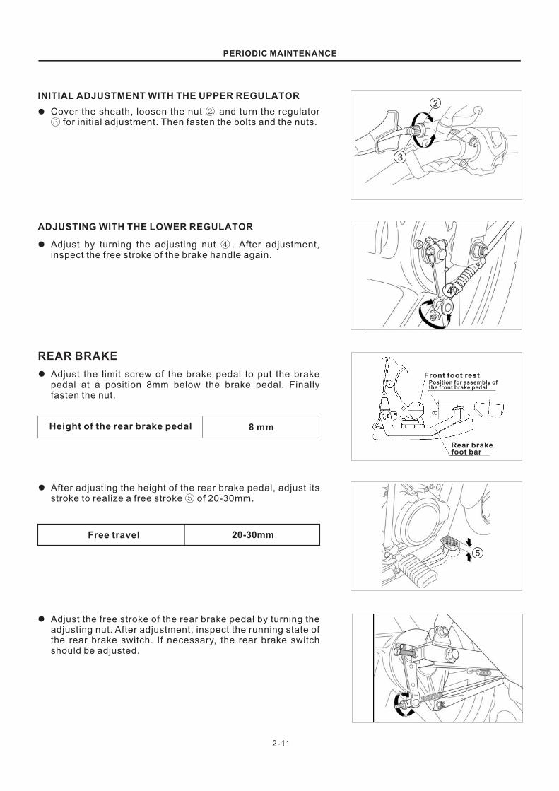
INITIAL ADJUSTMENT WITH THE UPPER REGULATOR
Cover the sheath, loosen the nut and turn the regulator
for initial adjustment. Then fasten the bolts and the nuts.
②③
●
ADJUSTING WITH THE LOWER REGULATOR
Adjust by turning the adjusting nut . After adjustment,
inspect the free stroke of the brake handle again.
④●
REAR BRAKE
Adjust the limit screw of the brake pedal to put the brake
pedal at a position 8mm below the brake pedal. Finally
fasten the nut.
●
20-30mmFree travel
8 mmHeight of the rear brake pedal
After adjusting the height of the rear brake pedal, adjust its
stroke to realize a free stroke of 20-30mm.⑤
●
Adjust the free stroke of the rear brake pedal by turning the
adjusting nut. After adjustment, inspect the running state of
the rear brake switch. If necessary, the rear brake switch
should be adjusted.
●
Front foot restPosition for assembly ofthe front brake pedal
Rear brakefoot bar

2-12
③
②
①
PERIODIC MAINTENANCE
Wear-off limit
Inspect Initial 1 000 km and Every 3 000 km
BRAKE WEAR-OFF
Inspect whether the brake system has been properly
adjusted.
After the adjustment, inspect whether the extension line is
within the range of the angle carved on the brake drum
when the braking-system is working.
If the extension line is beyond the range of the angle carved
on the brake drum (as shown in the right picture), the brake
shoe should also be replaced.
BRAKE LIGHT SWITCH
Step on the rear brake pedal to inspect the brake light switch.
If the brake light switch works inflexible, it may be adjusted by
turning the adjusting nut of the brake switch.
TIRES
There are multiple indicators of the wear sign position on
the peripheral direction of the tyre. Inspect the wear signs (the
bosses in the grooves) near the indicators , to make sure
the tread depth is enough and, if they have been worn, replace
the tyre.
Eyeballing the worn conditions and the damages (piercing
or cracks) of the tires surfaces. Excessive wear of tires or too
much damage on surfaces will lower the stability of riding. In
this case, please replace the tires.
①
② ①
③
As shown in the right picture, the wear limitation of the brake
shoe for a GD110HU motorcycle is carved on the brake drum.
Under normal wear conditions, the extension line of the brake
cam shaft should be within the range of the angle carved on
the brake drum. Inspect the wear situation of the brake shoe
by following the order.
●
●
●
1.75kg/cm2175KPa
2.00 kg/cm2200KPa
2.00 kg/cm2200KPa
2.25 kg/cm2225KPa
TIRE PRESSURE
SOLD RIDING DUAL RIDING
FRONT
REAR
Inspect the tyre pressure and check whether the valve cock
has air leakage.

2-13
PERIODIC MAINTENANCE
Inspect Initial 1 000 km and Every 3 000 km
STEERING
Properly adjust the bearing of the steering to make the
steering rotate flexibly and ensure safety during riding.
Too tight steering will make the rotation of the steering
inflexible.
Too loose steering will result in vibration and further damage
to the bearing. Inspect the steering to make sure it has no
shaking.
If the steering has shake, adjust it with the method stated in
(Refer to page 5-12).
Inspect Every 3 000 km
FRONT/REAR SUSPENSION
Grip the front brake, squeeze the front suspension to check
its motion, check for leaks or damage.
Replace damaged parts and tighten all bolts and nuts.
FRONT SUSPENSION●
REAR SUSPENSION
Press down the rear of the motorcycle repeatedly to check
the performance of the rear suspension
Check for leaks or damage; tighten all bolts and nuts.
●
●
●
ILLUMINATION AND SIGNAL
Inspect Initial 1 000 km and Every 3 000 km
Inspect the headlight, the left and right turn signal indicator
lights, the taillights or the brake lights and the signal lights on
the dashboard. If any problem, replace relevant light(s) in time
(Refer to page 6-6).

2-14
PERIODIC MAINTENANCE
Inspect Initial 1 000 km and Every 3 000 km
Check the tightening torque of the bolts and nuts for the motorcycle according to the table below:
CHASSIS AND ENGINE MOUNTING BOLTS AND NUTS
F
R
Front axle nut
Handlebar lock-up bolt/nut
ITEM
1
2
3
4
6
7
8
9
36~52
12~20
35~55
25~40
20~24
22-35
35~55
45~70
6-8
33-39
33-39
33-39
3.6~5.2
1.2~2.0
3.5~5.5
2.5~4.0
2.0~2.4
2.2-3.5
3.5~5.5
4.5~7.0
0.6-0.8
3.3-3.9
3.3-3.9
3.3-3.9
N m Kg m
5
60~100 6.0~10.0
10
11
12
13
14
15
22~33
22~33
2.2~3.3
2.2~3.3
T
F
T
Clamping bolt of the stem head
Steering bolt
Stem bolt (clamping bolt of the front absorber)
Bolt of the muffler cylinder head
Rear shock absorber bolt/nut
Rear axle nut
Bolt/nut of the rear swing arm shaft
Brake cam lever bolt/nut
Engine mounting bolt/nut
Bolt/nut of the engine plate

2-15
1 33
4
2
5
6
7
8
9
13
11
12
10
14
15
PERIODIC MAINTENANCE

2-16
2
1
PERIODIC MAINTENANCE
09915-64510 : Compression gauge
09915-63210 : Adapter
①
②
10-14kgf/cm2
8 kgf/cm2
COMPRESSION PRESSURE
INSPECTION
NOTE:Before testing the compression pressure of the engine, be
sure that the nuts and bolts of the cylinder head are securely
tightened with specified torque, and the air valve clearance is
correct.
Keep the engine running idle for several minutes before
carrying-out the test.
Remove spark plug.
Fit the compression gauge and adapter to the plug
hole, taking care to make the connection absolutely tight.
Twist the throttle grip into wide-open position.
Crank the engine several times with the starter motor, and
read the highest gauge indication as the compression of
the cylinder.
① ②
●
●
●
Compression pressure
Standard Limit
A low compression pressure may indication any of the
following malfunctions:
* Excessively worn cylinder wall.
* Worn piston or piston rings.
* Piston rings stuck in the grooves.
* Poor seating contact of valves.
* Defective cylinder head gasket.
When the compression pressure noted is down to or below the
limit indication above, the engine must be disassembled,
inspected and repaired as required.
Inspect Every 6 000 km
●

3
3 - 1
3 - 2
3 - 6
3-15
3-19
3-26
3-29
3-37
ENGINE
CONTENTS
REMOVING ENGINE PARTS WITH ENGINE UN-REMOVED
ENGINE REMOVAL AND REMOUNTING
CYLINDER HERD AND VALVE
CYLINDER AND PISTON
CLUTCH AND
GENERATOR
CRANKSHAFT, TRANSMISSION AND KICK START DEVICE
SECONDARY AIR SYSTEM
GEAR SHIFT MECHANISM
3-1
3-6
3-6
3-7
3-19
3-19
3-19
3-19
3-24
3-26
3-26
3-26
3-26
3-27
REMOVING ENGINE PARTS WITH ENGINE UN-REMOVED
The following parts can be removed and remounted without removing the engine. Refer to sections about
parts removing and remounting.
UPPER PART OF THE ENGINE
Engine sprockets cover
Cam chain tensioner
Engine sprocket
RIGHT SIDE OF ENGINE
LIFT SIDE OF ENGINE
Kick starter lever
Clutch cover
Clutch
Oil strainer
Gear shifting fork shaft
Gear lever
Oil filter
Generator cover
Generator rotor
Generator stator
ENGINE

3-2
ENGINE
ENGINE REMOVAL AND REMOUNTING
ENGINE REMOVALBefore taking the engine out of the frame, thoroughly clean
the engine with a suitable cleaner.
Open the lock and Remove the left and right covers.
Remove the leads of and terminals of the battery.
●
●
●
●
●
●
●
Unscrew the fixing bolts of the seat first and then Remove
the seat.
NOTICE
Remove the lead of terminal first.
Put the fuel cock onto position “ ”.
Remove the fuel hose.
●
Pull out the plug-terminals of the leads of the generator and
the gear indicator.
Unscrew the mounting bolts of the fuel tank, and disconnect
the plug connector of the fuel gauge and take off the fuel
tank.
1
2
3-3
ENGINE
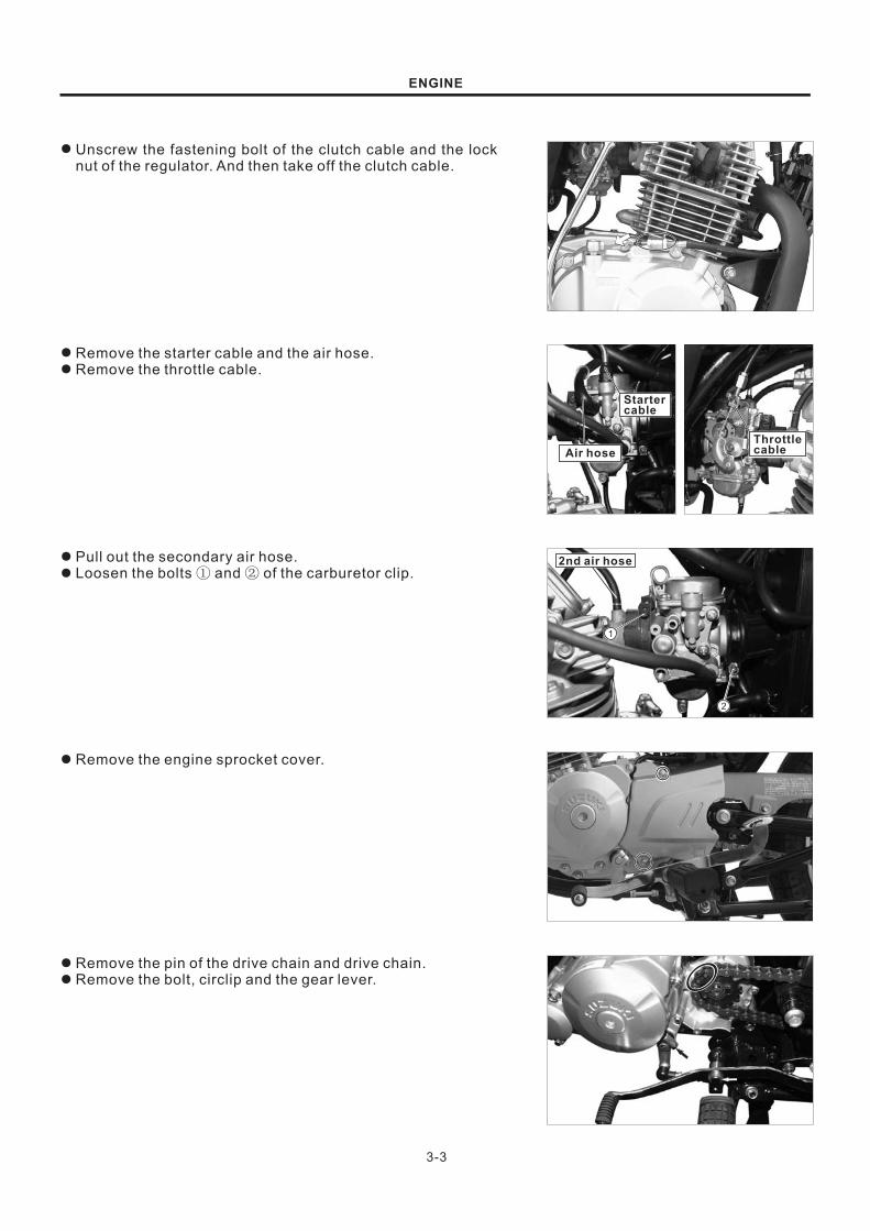
Unscrew the fastening bolt of the clutch cable and the lock
nut of the regulator. And then take off the clutch cable.
●
Remove the starter cable and the air hose.
Remove the throttle cable.
●
●
Pull out the secondary air hose.
Loosen the bolts and of the carburetor clip.① ②
●
●
Remove the engine sprocket cover.●
Remove the pin of the drive chain and drive chain.
Remove the bolt, circlip and the gear lever.
●
●
Startercable
Air hose
Throttlecable
2nd air hose

3-4
ENGINE
Pull out the air hose of the engine crankcase.●
Pull out the spark plug cap.●
Remove the bolt of muffler and the muffler.●
Pull out the secondary air hose.●
Unscrew the mounting bolts and nuts of the engine.
Take down the engine from the right side of the chassis.
Unscrew the bolt of the engine and Remove the plate of the
engine.
●
●
●
NOTE:
The engine must be taken out from the right side of the chassis.

Mounting bolt (front) ① 33-39 N m
Mounting bolt (rear) ② 33-39 N m
Mounting bolt (top) ③ 33-39 N m
Bolt of the rear swingarm shaft ④ 45-70 N m
Overhang bolt (top) ⑤ 22-33N m
Overhang bolt (front) ⑥ 22-33N m
3-5
ENGINE
ENGINE REMOUNTINGThe mounting of the engine may follow the steps opposite the
Removing steps.
Pre-fix the plate of the engine before inserting the mounting
bolt.
NOTE:If Remove this mounting nut. Replace a new one, and
tightened till the specified torques.
●
The tightening torques of the mounting bolts:
Tighten the bolt and nut of the muffler.
After an overhaul of the engine, fill 1.1L engine oil of grade
SAE 10W-40, SF or SG into the crankcase.
Start the engine and make it run at the idle for couple
seconds.
Stop the engine for about one minute, Remove the dip stick
or the oil filler cover, and clean it before inserting it again.
Take out the dip stick to check the engine oil level. If the
engine oil level is lower than the lower limit, fill some engine
oil till it reaches the upper limit. Remount the dip stick.
●
●
●
●
After remounting the engine, inspections should be done for
the following parts:
* Clutch cable (Refer to page 2-8)
* Throttle cable (Refer to page 2-9)
* Idle speed (Refer to page 2-8)
* Drive chain (Refer to page 2-10)
●
1
6
355
2
4

3-6
ENGINE
CYLINDER HEAD AND VALVE
CYLINDER HEAD REMOVAL
Remove the engine (Refer to page 3-2).
Drain out the engine oil.
Remove the bolt of chain tensioner and the tensioner.
●
●
●
Remove the timing inspection screw plug of valve and the
screw plug of the generator rotor.
●
Remove the bolts of the engine sprocket cover and the
sprocket cover.
●
Remove the access hole covers of the inlet valve and the
exhaust valve as well as the spark plug.
●
Raise the piston to the TDC (Refer to page 2-5).
NOTE:When take down the cylinder head cover, the piston must
locate at the TDC of the compressions stroke.
●
3-7
Pin
ENGINE
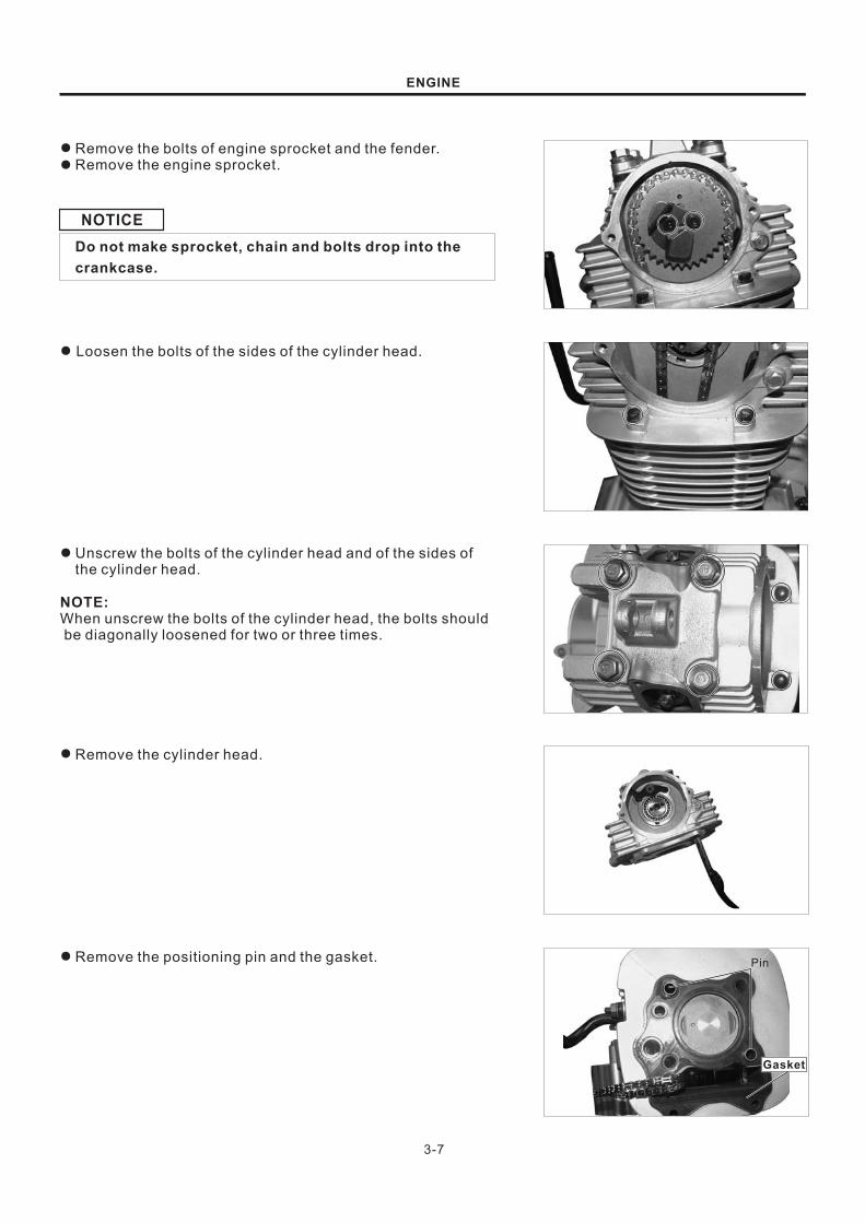
Remove the bolts of engine sprocket and the fender.
Remove the engine sprocket.
●
●
NOTICE
Do not make sprocket, chain and bolts drop into the
crankcase.
Loosen the bolts of the sides of the cylinder head.●
Unscrew the bolts of the cylinder head and of the sides of
the cylinder head.
●
NOTE:When unscrew the bolts of the cylinder head, the bolts should
be diagonally loosened for two or three times.
Remove the cylinder head.●
Remove the positioning pin and the gasket.●
Gasket

3-8
ENGINE
CYLINDER HEAD DISASSEMBLY
Remove the bolt of the cam chain guide and the cam chain
guide.
●
Remove the camshaft, bolt of the swing arm shaft, and
Remove the positioning plate.
Pull out the camshaft, rocker arm shaft and then Remove
the arm valve rocker.
Remove the valve spring with specified tools.
Loosen the valve detacher and Remove the following parts:
Spring seat
Internal and external valve springs
Spring retainers
Inlet valve and exhaust valve
Valve oil seals .
●
NOTE:In order to make the mounting correct, all Removeed parts
should be marked.
●
●
●
11F14-018 : Valve spring knocked-down tool

3-9
1
Standard 9.981~9.990mm
09900-20205 : Micrometer (0-25mm)
ENGINE
Remove the carbon deposit in the combustion chamber.●
CYLINDER HEAD INSPECTIONSWING ARM SHAFT
Measure the outer diameter of the swing arm shaft.
SWING ARM
Measure the inner diameter of the swing arm, and inspect
the wear situation of the swing arm contact surface with the
cam.
10.003~10.018mm
09900-20605: Internal micrometer
Standard
CAMSHAFT
If the engine has abnormal sound, shaking or insufficient
output power, should inspect the cam wear situation and the
camshaft run-out.
The wear of the camshaft always results in the poor
operation of the inlet valve and the exhaust valve and
further declined engine power. The wear loss of the
camshaft is determined by the heights of the inlet cam
and the exhaust cam. If the wear losses of the cams exceed
the limit values, please replace the camshaft.
①
Inlet cam 27.54mm
Exhaust cam 27.35mm
09900-20202: Micrometer (25-50mm)
Height
(limit)
①
●
●
●
●

34.20 mm
34.20 mm
3-10
09900-20201: Slide caliper (150mm)
ENGINE
VALVE SPRING
Measure the free lengths of the valve springs.●
Service limitIN
EX
CYLINDER HEAD
Inspect whether the spark plug hole and the valve base
have scratches.
Inspect the cylinder head with a thickness gauge to see
whether it has deformed.
●
●
0.05 mm
09900-20803: Thickness gauge
Service limit
NOTE:Do not damage the gasket plane.
VALVES
Inspect whether the valves suffer from bending, ablation,
drag marks or abnormal abrasion.
Measure the outer diameters of the valves.
●
●
4.975-4.990mm
4.955-4.970mm
IN
EX
Standard
09900-20205 : Micrometer (0-25mm)
As shown in the right picture, support valves with a V-
shaped block and measure its run-out with a dial indicator.
If the measured value exceeds the limit value, the valves
should be replaced.
●
09900-20701: Magnetic stand09900-20606: Dial indicator09900-21304: V-shaped block
0.05 mmService limit
INSPECTION OF THE VALVE SEAT
Clean valve seat thoroughly to remove the carbon deposit.
Apply gently a coat of Prussian blue onto the valve seats.
Grind valves with a rubber stick or other tools.
●
●
●
3-11
0.9-1.1mm
���
30o
45o
60o
ENGINE
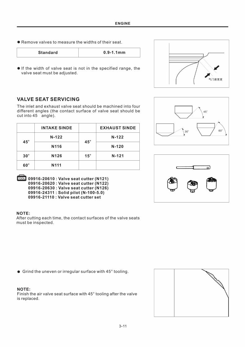
Remove valves to measure the widths of their seat.●
Standard
If the width of valve seat is not in the specified range, the
valve seat must be adjusted.
●
VALVE SEAT SERVICING
The inlet and exhaust valve seat should be machined into four
different angles (the contact surface of valve seat should be
cut into 45 angle).
45o
15o
EXHAUST SINDE
N-122
N-120
N-121
45o
30o
60o
INTAKE SINDE
N-122
N116
N126
N111
09916-20610 :09916-20620 :09916-20630 : )09916-24311 :09916-21110 :
Valve seat cutter (N121)Valve seat cutter (N122)Valve seat cutter (N126Solid pilot (N-100-5.0)Valve seat cutter set
NOTE:After cutting each time, the contact surfaces of the valve seats
must be inspected.
Grind the uneven or irregular surface with 45° tooling.●
NOTE:Finish the air valve seat surface with 45 tooling after the valve
is replaced.
°

3-12
30
o
60
o
0.9-1.1mm
45
o
30
o
Contract surface of the valve is too high
60
o
ENGINE
0.9 1.1mm~
Grind the top surface of the original valve seat by 1/4 of its
width with 30 tooling.°
●
Grind the bottom of the original valve seat by 1/4 of its
width with 60 tooling.°
●
Process the valve seat surface to standard height with 45
tooling.
Make sure all pitting and irregular surfaces have been cut.
If necessary, adjust it again.
°●
Standard
Wid
ths
of
valveseats
Wid
ths
of
valveseats
Apply a thin coat of Prussian blue onto the valve seat.
Press the valve onto the valve seat and make it rotate for
couple times. After that, take out the valve and observe the
contract surface of the valve seat. There should be clear
traces on the contract surface.
●
●
●
NOTE:The position of the valve seat has affect on the contract
surface of the valve, which is of great significance for good
sealing.
If the contract surface of the valve is too high, cut it lower
with a 30 angle milling cutter.
If the contract surface of the valve is too low, adjust it with a
60 angle milling cutter.
Cut the valve seat to the standard width with a 45 angle
milling cutter.
●
●
●
After cutting the valve seat, apply an abrasive coat onto the
valve surface, and gently grind the valve. After grinding,
clean all left abrasive of the cylinder head and the valve.
Inspect the contact surface of the valve seat again.
●
NOTICE
Too big grinding force will possibly result in deformationor damage to the valve seat. Please change the workingangle of the grinding tool frequently, in order to avoiduneven grinding of the valve . If the abrasive entersinto the space between the valve stem and the valveguide pipe, it will possibly result in damage
seat
Contract surface of the valve is too low

3-13
99000-25140: Molybdenum oil solution
ENGINE
CYLINDER HEAD ASSEMBLY
Clean the cylinder head thoroughly with a cleaning liquid
and blow all passages with compressed air.
Mount a new valve oil seal.
Lubricate all valves with molybdenum oil solution.
Insert the valves into air guide pipes and mount spring
washers, springs and spring bases for the valves.
●
●
●
●
NOTE:When a valve spring is mounted, the seal ring side should face
the combustion chamber. In order to avoid oil seal damage,
the valve oil seal should be mounted while the valve is rotating
slowly.
Mount a valve lock clamp.●
11F14-018 : Valve spring knocked-down tool
Mount a swing arm and a swing arm shaft for the valve.●
NOTE:During mounting, do remember to mount the corrugated
gasket of the inner side of the swing arm.
When the swing arm shaft is mounted, the end near the oil
passage hole of the swing arm should face inward.
Mount the camshaft and firmly lock the baffle bolt.
Mount the timing chain guide rod.
●
●
Mount the cylinder head.
Mount the bolts of the cylinder head and that of the side of
the cylinder head, and tighten them with the specified
torques.
●
●
Bolts of the cylinder head: 23-27N m
Bolts of the side of the cylinder head: 8-12N m
M

3-14
Timing sprocket bolt: 3-6 N m
99000-32030: Apply thread lock super “1303”
ENGINE
Mount the timing chain and the sprocket and make the
timing marks aligned.
Apply a little onto the bolt of timing
sprocket and tighten the timing sprocket bolt with the
specified torque.
thread lock super
●
●
Mount the timing sprocket cover and its bolts.
Mount the timing access hole plug.
●
●
Adjust the tensioner with screwdriver.
Mount the chain tensioner and tighten its bolt.
Mount the engine (Refer to page 3-6).
●
●
●

3-15
Y
X
0.05mm
ENGINE
CYLINDER AND PISTON
CYLINDER DISASSEMBLY
Remove the cylinder head (see 3-6 Page ).
Remove the washer and the pin.
Remove the cylinder .
●
●
●
● Remove the guide rod and the second air hose.
CYLINDER INSPECTION
Remove the residual gasket of the cylinder surface.
Inspect the plainness of the cylinder with a ruler and a
thickness gauge
●
●
09900-20803: Thickness gauge
Service limit
Inspect whether the inner part of the cylinder is worn or
damaged.
Measure the inner diameter of the cylinder along directions
X and Y respectively. Three horizontal planes vertical to the
axis should be selected for measurement. Using the
maximum valve as reference when judging whether the
cylinder is worn.
●
●
51.135mm
09900-20508 : Cylinder gauge setTOOL
Servicing limit
DISASSEMBLY AND INSPECTIONOF THE PISTONDISASSEMBLY
NOTE:Block the crankshaft plane with a piece of clean cloth lest the
piston pin or other parts drop into the crankcase.
Remove
Remove
piston pin retainer with pliers.
piston pin and piston.
●
●
Washer
Pin

3-16
10mm
ENGINE
● Remove the piston ring.
Be careful not to damage the piston ring duringdisassembly.
NOTICE
0.12mm
0.12mm
Remove the carbon in the piston ring slot with the old piston
ring.
Push the piston ring into the slot, measure the clearance
between the piston ring and the ring slot.
Servicing limitPiston ring
1st
2nd
●
●
INSPECTION
09900-20803: Thickness gauge
09900-20202 : Micrometer (25~50mm)
09900-20605 : Dial calipers
09900-20205 : Micrometer (0~25mm)
TOOL
TOOL
Check for damage or wearing of the piston.
Measure the piston O.D. at 15mm along the vertical
direction of the piston pin.
Servicing limit
Measure the hole inner diameter of the piston pin.
Measure the outer diameter of the piston pin.
●
●
●
50.840mm
14.038mm
●
13.976mm
Servicing limit
Servicing limit

14.006~14.024
3-17
ENGINE
Measure the inner diameter of the smaller end of
connecting rod.
●
09900-20605 : Dial calipers
Standard
0.5mm
0.5mm
Put the piston ring horizontally on the cylinder bottom to
measure the opening clearance.
Piston ring Servicing limit
1st
2nd
●
PISTON RING ASSEMBLY
Clean the piston ring slot completely and assemble the
piston ring.
●
●
●
NOTE:Apply Molybdenum oil solution on all piston rings.
Avoid damaging the piston and piston ring during assembly.
Align the mark on the piston ring upward during assembly, pay
attention to distinguish the marks of the top ring and the
second ring.
Keep the opening of each ring cross at 120°, do not leave
the oil ring opening on the same line.
The piston ring must be able to rotate freely in the ring slot
after installation.
09900-20803: Thickness gauge
NOTE:When using the piston head to jack the piston rings into the
cylinder, make sure they enter evenly.
3-18
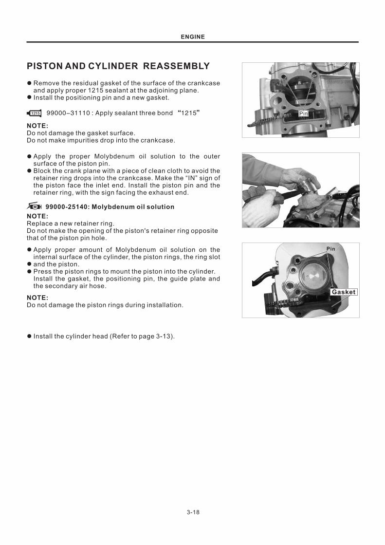
99000-31110 : Apply sealant three bond “1215”
Pin
Pin
ENGINE
PISTON AND CYLINDER REASSEMBLY
Remove the residual gasket of the surface of the crankcase
and apply proper 1215 sealant at the adjoining plane.
Install the positioning pin and a new gasket.
●
●
NOTE:Do not damage the gasket surface.
Do not make impurities drop into the crankcase.
Apply the proper Molybdenum oil solution to the outer
surface of the piston pin.
Block the crank plane with a piece of clean cloth to avoid the
retainer ring drops into the crankcase. Make the “IN” sign of
the piston face the inlet end. Install the piston pin and the
retainer ring, with the sign facing the exhaust end.
●
●
NOTE:Replace a new retainer ring.
Do not make the opening of the piston's retainer ring opposite
that of the piston pin hole.
Apply proper amount of Molybdenum oil solution on the
internal surface of the cylinder, the piston rings, the ring slot
and the piston.
Press the piston rings to mount the piston into the cylinder.
Install the gasket, the positioning pin, the guide plate and
the secondary air hose.
●
●
●
NOTE:Do not damage the piston rings during installation.
Install the cylinder head (Refer to page 3-13).●
99000-25140: Molybdenum oil solutionM
Gasket

3-19
3
1
2
ENGINE
CLUTCH AND GEAR SHAFTMECHANISMCLUTCH COVER DISASSEMBLY
Drain out the engine oil completely.
Loosen the adjusting bolts and of the clutch.
Make the cable and the release swing arm separate.
Unscrew the screw and Remove the kick starter.
① ②
③
Remove the bolts and the clutch cover then.
●
●
●
●
DISASSEMBLY AND REASSEMBLY OFTHE CLUTCH ARM
Remove the gasket and the positioning pin.
Put the tooth stopper between the primary gear and the
drive gear for fixing the crank. Remove the balancer
retaining nut, the gasket, the balancer and the bush.
Remove the oil strainer.
●
●
●
NOTE:Diagonally loosen the bolts by two or three steps.
Remove the cotter pin, the shaft and the clutch release
swing arm.
Inspect carefully to see whether the clutch release swing
arm is bent or worn.
Reassemblyl the clutch release swing arm onto the clutch
cover in opposite order of Removeing order.
●
●
●
NOTE:Install the clutch arm at the position shown in the picture.
CLUTCHDISASSEMBLY
●

3-20
11F14-014 : Tooth stopper
11F14-001 Rotor holder:TOOL
ENGINE
Remove the push rod spring of the clutch.●
Remove the clutch push rod and bearing and its lock nut
and two gaskets then.
Remove the clutch drive plates and driven plates.
Remove the primary drive gear and the clutch hubs.
●
●
●
DISASSEMBLY AND INSPECTION
CLUTCH
Fix the clutch exterior with a rotor clamps first, and loosen
and Remove the push plate bolts, the push plate and the
spring in order.
●

3-21
35.28mm
09900-20101: slide caliper (150mm)
2.60mm
ENGINE
Remove the clutch drived hub, friction discs and driven
discs.
Remove the pressure disc.
●
● Driven hub
Friction discs
Driven discs
Pressure disc
INSPECTION
Inspect whether the bearing is damaged.
Turn the bearing cone with a finger.
Replace the bearing if necessary.
●
●
●
Measure the free lengths of the clutch springs●
Service limit
NOTE:If one or more clutch springs exceed the use limit, the whole
set springs must be replaced.
If the drive friction discs of the clutch have scratches or
discoloration phenomenon, they should be replaced.
Measure the thicknesses of the friction discs.
●
●
09900-20101: slide caliper (150mm)
Service limit
Checking thickness
Measure the thicknesses of the drive friction discs.●
11.00mmService limit
09900-20101: slide caliper (150mm)
NOTE:If the drive friction discs exceed the use limit, the whole set
friction discs must be replaced.Checking claw width

3-22
ENGINE
Checking distortion
Measure each driven disc for distortion with a thickness
gauge. Replace driven disc which exceed the limit.
●
Service limit 0.10mm
09900-20803 : Thickness gauge
Driven hub
Friction disc
Driven disc
Pressure disc
Reassemble the drive friction disc and the driven friction
disc.
●
REASSEMBLY
Reassembly the balancer and the clutch.●
NOTE:Before reassembly the two clutch nuts, inspect whether the two
gaskets have been correctly installed.
Use special tools to fix the primary drive gear and the
driving gear. Install the balancer and the clutch nuts with
the specified torques.
●
11F14-014 : Tooth stopper
Specified torque: 40~60 N m
Install the push rod onto the clutch and install the spring
then.
●
Install the positioning pin and new gaskets.●

3-23
1
2
3
ENGINE
Install the clutch cover.
Install the bolts and tighten them with the specified torques.
●
●
Specified torque: 8~12 N m
NOTE:Diagonally tighten the bolts by two or three steps.
Install the kick starter and tighten the bolt.●
Connect the clutch cable with the release swing arm.
Install the clutch cable and tighten the bolt.
Fill engine oil into the crankcase till the marker line of the
upper limit is reached.
Inspect and adjust the clutch cable free play (Refer to page
●
●
●
●
GEAR SHAFT MECHANISM
DISASSEMBLY
Remove the bolts, the retainer rings and the gear shift
pedal.
Remove the clutch (Refer to page 3-19).
●
●
Remove the bolt , the clamp arm and the return spring
.
① ②③
●
3-24
99000-32050 : Apply thread lock super “1342”
2
1
3
4
ENGINE
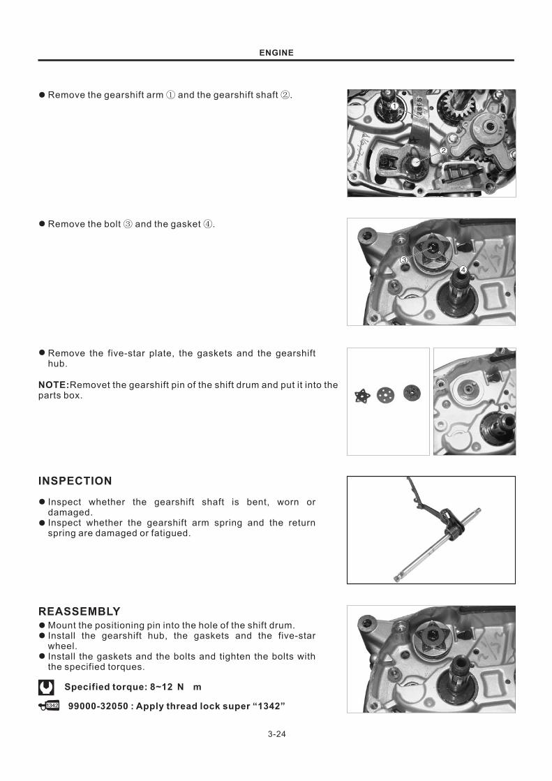
Remove the gearshift arm and the gearshift shaft .① ②●
Remove the bolt and the gasket .③ ④●
Remove the five-star plate, the gaskets and the gearshift
hub.
●
NOTE:Removet the gearshift pin of the shift drum and put it into the
parts box.
INSPECTION
Inspect whether the gearshift shaft is bent, worn or
damaged.
Inspect whether the gearshift arm spring and the return
spring are damaged or fatigued.
●
●
REASSEMBLY
Mount the positioning pin into the hole of the shift drum.
Install the gearshift hub, the gaskets and the five-star
wheel.
Install the gaskets and the bolts and tighten the bolts with
the specified torques.
●
●
●
Specified torque: 8~12 N m

3-25
ENGINE
Install the gearshift shaft and the gearshift arm spring.
Install the spring of gearshift shaft swing arm, the gaskets,
the swing arm and the bolts and tighten the bolts with the
specified torques.
●
●
99000-32050 : Apply thread lock super “1342”
Specified torque: 15~23 N m
Install the detaching cam of the clutch.●
Install the clutch subassembly (Refer to page 3-22).
Install the gear lever.
●
●

3-26
ENGINE
GENERATORDISASSEMBLY OF THE GENERATOR COVER
Remove the generator connector, the induction coil
connector and the gear switch connector.
Remove the bolts of gearshift pedal lever and the gearshift
pedal lever then.
●
●
Remove the engine sprocket cover.
Remove the bolts, the oil filter cover and the oil filter
element in order.
●
●
Remove the bolts of generator cover and the generator
cover then.
●
NOTE:Loosen the bolts of generator cover in a diagonal order.
Remove the gaskets and the positioning pin.●
The generator cover (mounted with a stator) and therotor is magnetized. So Remove them carefully.
NOTICE
ROTOR
Fix the rotor with the generator rotor fixture and Remove the
bolts and gaskets of the rotor then.
●
11F14-001 : Rotor holder

3-27
11F14-005 : Rotor separator
11F14-001 : Rotor holder
Bolts for the rotor 50~70: N m
ENGINE
Remove the generator rotor and keys.●
NOTE:Be careful when Remove the keys; avoid damaging the key
slot and the crank.
REASSEMBLY
Install the keys into the crank key slot.●
NOTE:Be careful when installing the keys to make sure the key slot
and the crank are not damaged.
Make the key slot of the rotor align with the key of the crank
to install the rotor.
Install the bolt of the rotor of the generator and tighten it
with the specified torque.
●
●
99000-32050 : Apply thread lock super “1342”
STATOR
DISASSEMBLY
Remove the bolts, cable guide, the stator and the induction
coil.
●
REASSEMBLYInstall the stator and the cable guide, apply the proper
amount of anti-loosening glue of the screws and finally
tighten the screws.
Install the induction coil, apply proper amount of anti-
loosening glue on the screw heads and finally tighten the
screws with the specified torque.
●
●
99000-32050 : Apply thread lock super “1342”
Bolts for the stator 8~12: N m
3-28
ENGINE
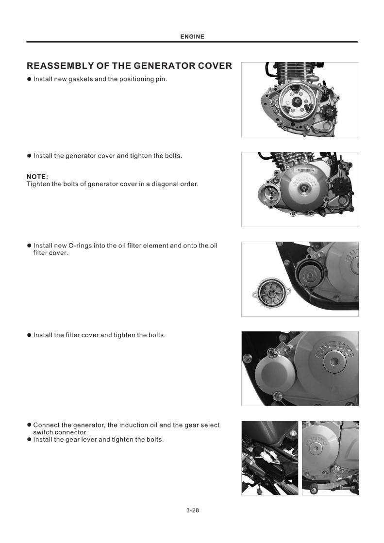
REASSEMBLY OF THE GENERATOR COVER
Install new gaskets and the positioning pin.●
Install the generator cover and tighten the bolts.●
NOTE:Tighten the bolts of generator cover in a diagonal order.
Install new O-rings into the oil filter element and onto the oil
filter cover.
●
Install the filter cover and tighten the bolts.
Connect the generator, the induction oil and the gear select
switch connector.
Install the gear lever and tighten the bolts.
●
●
●

3-29
11F14-002 : Crankcase separating tool
ENGINE
CRANKSHAFT, TRANSMISSIONAND KICK STARTER DEVICE
CRANKCASE DISASSEMBLY
Remove the cylinder head, the cylinder and the piston
(Refer to page 3-6).
Remove the clutch and the gear system (Refer to page 3-
19).
Remove the generator rotor and stator (Refer to page 3-29).
●
●
●
●
Remove the left crankcase bolt.●
NOTE:Diagonally loosen the bolts by two or three steps.
Remove the oil pump bolts.
Integrally Remove the oil pump drive gear and the oil pump.
●
●
Put the crankcase at the bottom and separate the left and
right parts of the crankcase with special tools.
●
NOTICE
Do not try to prize up the crankcase with a screwdriver.
Remove the positioning pin.●

0.3mm
0.05mm
3-30
09900-20803 : Thickness gauge
09900-20606: dial indicator (1/100)09900-20701: magnet stand09900-21304: V-shaped block
3.0mm
ENGINE
CRANKSHAFT
Remove the crank from the crankcase.●
INSPECTION
Measure the gap of the connecting rod big end with a
thickness gauge.
●
Service limit
The abrasion situation of the connecting rod big end may be
estimated by inspecting the run-out situation of the
connecting rod small end. This method can also be used for
inspecting the degree of wear of other big-end parts.
●
Service limit
Put the crank on the V-shaped block and measure its radial
run-out with a dial indicator.
●
Standard
INSPECTION OF THE CRANK BEARING
Turn the crank bearing cones with a finger.
The crank bearing should turn smoothly.
Inspect whether the crank bearing cups turn in the
crankcase.
If the crank bearing cones fail to turn smoothly or the crank
bearing cups turn in the crankcase, the crank bearing
should be replaced with a new one.
●
●
●
●

3-31
ENGINE
TRANSMISSIONDISASSEMBLY
Remove the shift fork shaft.●
Remove the shift forks.
Remove the primary shaft, the gear and the secondary shaft
first gear.
●
●
Remove the secondary shaft and the shift cam.●
INSPECTION
Inspect the guide slot of the shift cam.
If the guide slot of the shit cam is damaged, the shift cam
should be replaced with a new one.
Inspect the gaps between the shift forks and the tooth
groove. If the gaps exceed the limit value, whether to
replace the shift forks or the gear are according to
measuring width of the tooth groove and the thicknesses of
the shift forks.
●
●
●
0.10~0.30mm
0.50mm
09900-20803 : Thickness gauge
Standard
Service limit
Checking clearance

4.30-4.40mm
3-32
09900-20101: Vernier caliper
ENGINE
Checking groove width
Checking thickness
Standard
Measure the thicknesses of the shift forks.●
4.50~4.60mm
09900-20101: Vernier caliper
Standard
Measure the width of the shift fork groove.●
INSPECTION OF THE TRANSMISSION
Inspect whether the inner surfaces of the bushes and gears
as well as the tooth surfaces of the gears have abnormal
abrasion or poor lubrication.
●
REPLACE OF THE TRANSMISSION BEAR
Turn each bearing with a finger to inspect whether it turns
smoothly. Inspect whether the bearing cups turn in the
crankcase and, if they do, replacement is necessary.
●
Remove the secondary shaft oil seal.●

3-33
09923-73210 : Bearing puller09930-30102 : Rotor remove slide shaft
09940-53311 : Bearing installer09924-84510 :09913-75820 :09913-80112 :
Bearing installerBearing installerBearing installer
ENGINE
Remove the bolts of primary shaft bearing and fender from
the right crankcase first and the bearing then.
Remove the secondary shaft' needle roller bearing and
crank bearing from the right crankcase with dedicated tools.
●
●
Remove the secondary shaft bearing from the left
crankcase.
Remove the primary shaft bearing from the left crankcase
with dedicated tools.
●
●
09923-73210 : Bearing puller09930-30102 : Rotor remove slide shaft
Install new bearings with the following dedicated tools.●
REASSEMBLY OF THE TRANSMISSION
Install the transmission gear, the primary shaft and the
secondary shaft.
Inspect whether the transmission gear moves smoothly and
turns flexibly on the primary shaft and the secondary shaft.
Inspect whether the retainer ring is in the groove.
●
●
●
Install the secondary shaft and the shift cam onto the
crankcase.
●

3-34
ENGINE
Primary shaft shift fork
Secondary shaft shift fork
NOTE:Install the shift forks with the method shown in the right picture.
Install the primary shaft, the shift forks and the shift fork
shafts.
After installation, inspect whether the transmission runs
smoothly.
●
●
KICK START DEVICE
DISASSEMBLY
Loosen the ratchet positioning plate bolts and Remove the
subassembly of the kick start assembly positioning plate
and the kick start assembly.
●
Disassemble the kick starter in the following order:
Remove the spring bushing, the kick starting spring and a
retainer ring.
Remove the other retainer ring and the kick starting gear.
Remove the ratchet and its spring.
●
*
**
REASSEMBLY
Install the spring bushing, the kick starting spring and a
retainer ring.
Install the ratchet spring and the ratchet.
Install the kick starting gear and the other retainer ring.
●
●
●
3-35
ENGINE
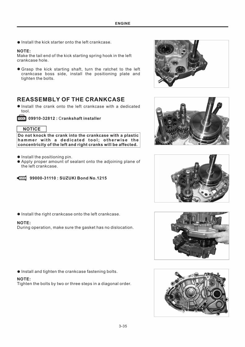
Install the kick starter onto the left crankcase.●
NOTE:Make the tail end of the kick starting spring hook in the left
crankcase hole.
Grasp the kick starting shaft, turn the ratchet to the left
crankcase boss side, install the positioning plate and
tighten the bolts.
●
REASSEMBLY OF THE CRANKCASE
09910-32812 : rankshaft installerC
Install the crank onto the left crankcase with a dedicated
tool.
●
NOTICE
Do not knock the crank into the crankcase with a plastich a m m e r w i t h a d e d i c a t e d t o o l ; o t h e r w i s e t h econcentricity of the left and right cranks will be affected.
Install the positioning pin.
Apply proper amount of sealant onto the adjoining plane of
the left crankcase.
●
●
99000-31110 : SUZUKI Bond No.1215
Install the right crankcase onto the left crankcase.●
NOTE:During operation, make sure the gasket has no dislocation.
Install and tighten the crankcase fastening bolts.●
NOTE:Tighten the bolts by two or three steps in a diagonal order.

3-36
ENGINE
Integrally install the oil pump drive gear and the oil pump
and tighten the oil pump bolts.
●
Install the drive sprocket and the catch and tighten the
bolts.
●
Reinstall the clutch component (Refer to page 3-22).
Reinstall the generator component (Refer to page 3-22).
Reinstall the cylinder head and the cylinder (Refer to page
3-13 and page 3-18).
Reinstall the engine (Refer to page 3-5).
●
●
●
●

SECONDARY AIR SYSTEM
3-37
Fasten and the motorcycle⑥
A
A
ENGINE
When the engine is started, fresh air will flow through the air filter, intake pipe, secondary air valve and
secondary intake tube to blend with the exhaust gas generated by in-engine combustion for secondary
combustion, and the exhaust gas will be expelled through the exhaust pipe.
NOTE:When the secondary air intake duct is inserted into the secondary air hose, avoid distortion of the secondary
air intake duct.
The length of the secondary air intake duct in the secondary air hose should be 15-20mm.
Keep the hose away from the cylinder head
Keep the hose away fromthe secondary air valv
1.Components of the secondary air hose2.Secondary air hose gasket3.Secondary air valve assembly4.Secondary air intake duct5.Secondary air admission hose6.Secondary air negative pressure hose7.Negative pressure hose hoop
8. Secondary air intake duct hoop9. Secondary air admission hose hoop10. Secondary air hose stud bolt11. Secondary air valve bolt12. Secondary air hose nut13. Secondary air negative pressure hose strap

5
4
3
2
1
Leaf valve
Valve seat
3-38
67
8
ENGINE
SCHEMATIC PLAN
Secondary air valve
Negative
Air cleaner
Carburetor
Exhaust pipe
REMOVAL AND INSPECTION
Remove the fixing bolt of secondary air valve.
Pull out the admission hose , the negative pressure hose
and the intake duct and Remove the secondary air
valve .
Inspect whether the admission hose or the intake duct is
damaged, distorted or ruffled and, if it is, it should be
replaced with a new one.
⑤①
② ③④
●
●
●
Remove the four screws and take down the leaf valve
cover .
⑥⑦
●
Take down the leaf valve and inspect whether its gasket
is damaged and, if it is, replace the leaf valve.
Inspect whether the leaf valve and the valve base fit each
other firmly. Inspect whether the leaf is deformed and, if it
is, replace the leaf valve.
⑧●
●
REASSEMBLYInstall the secondary air valve in opposite order of
Removeing order.
●
FUEL COCK
CARBURETOR
LUBRICATION SYSTEM
4-1
4-3
4-7
4
FUEL AND LUBRICATION
CONTENTS
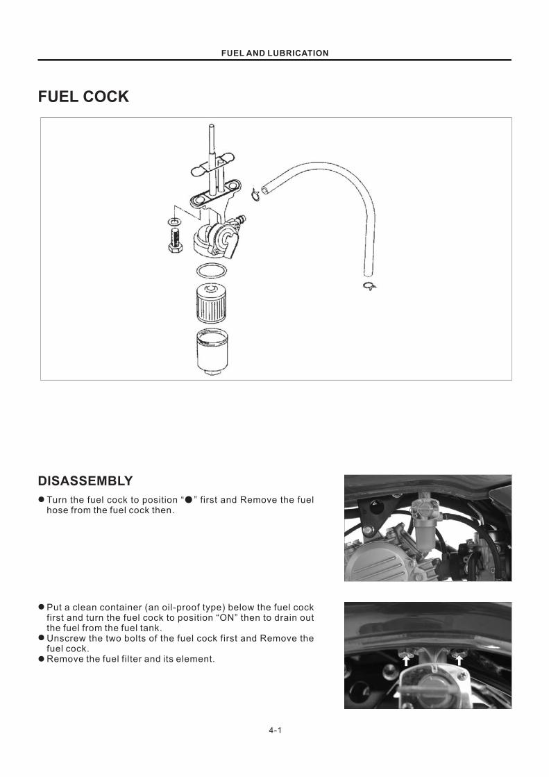
DISASSEMBLY
FUEL COCK
4-1
FUEL AND LUBRICATION
Turn the fuel cock to position “ ” first and Remove the fuel
hose from the fuel cock then.
●●
Put a clean container (an oil-proof type) below the fuel cock
first and turn the fuel cock to position “ON” then to drain out
the fuel from the fuel tank.
Unscrew the two bolts of the fuel cock first and Remove the
fuel cock.
Remove the fuel filter and its element.
●
●
●
4-2
FUEL AND LUBRICATION
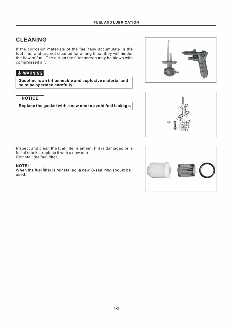
CLEANING
If the corrosion materials of the fuel tank accumulate in the
fuel filter and are not cleaned for a long time, they will hinder
the flow of fuel. The dirt on the filter screen may be blown with
compressed air.
Gasoline is an inflammable and explosive material andmust be operated carefully.
NOTICE
Replace the gasket with a new one to avoid fuel leakage.
Inspect and clean the fuel filter element. If it is damaged or is
full of cracks, replace it with a new one.
Reinstall the fuel filter.
NOTE:When the fuel filter is reinstalled, a new O-seal ring should be
used.
WARNING
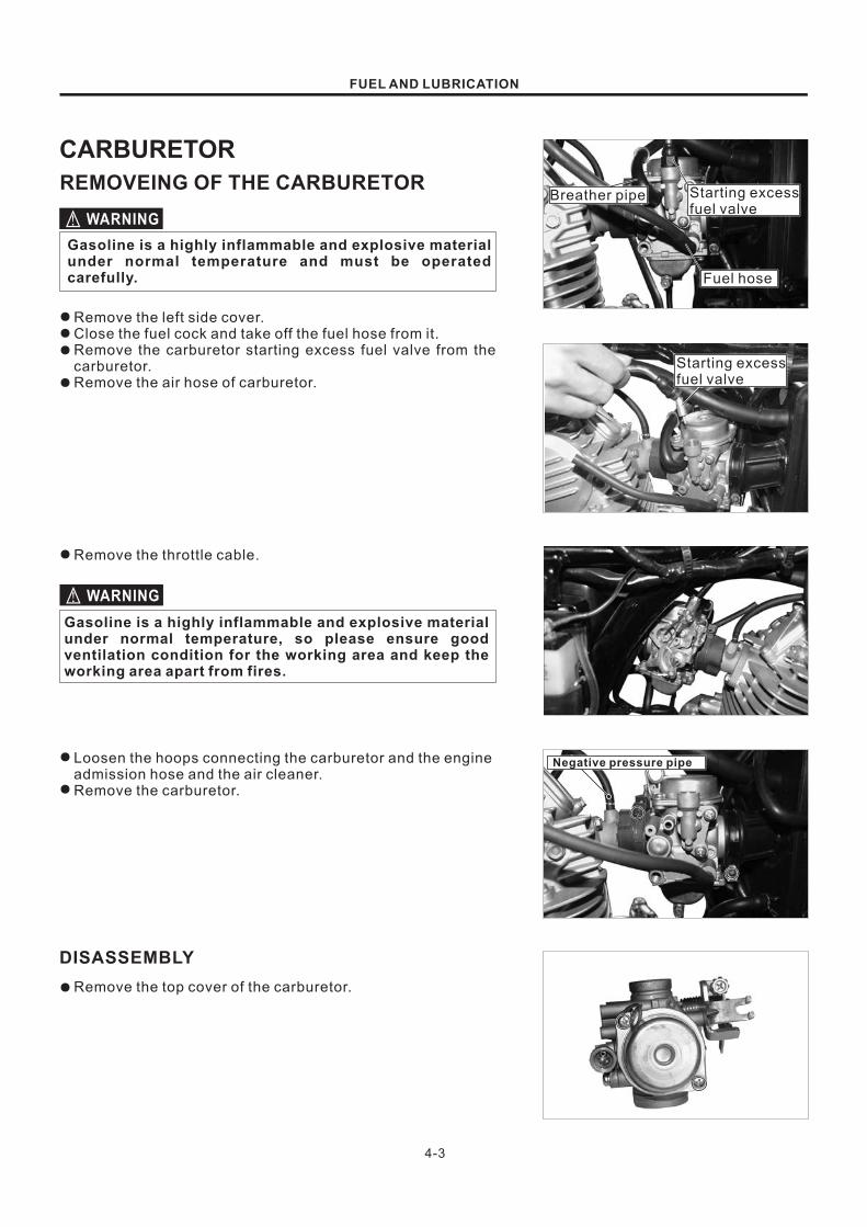
REMOVEING OF THE CARBURETOR
4-3
DISASSEMBLY
FUEL AND LUBRICATION
Gasoline is a highly inflammable and explosive materialunder normal temperature and must be operatedcarefully.
Remove the left side cover.
Close the fuel cock and take off the fuel hose from it.
Remove the carburetor starting excess fuel valve from the
carburetor.
Remove the air hose of carburetor.
●
●
●
●
Remove the throttle cable.●
WARNING
WARNING
Gasoline is a highly inflammable and explosive materialunder normal temperature, so please ensure goodventilation condition for the working area and keep theworking area apart from fires.
Loosen the hoops connecting the carburetor and the engine
admission hose and the air cleaner.
Remove the carburetor.
●
●
Remove the top cover of the carburetor.●
Breather pipe Starting excess
fuel valve
Fuel hose
Negative pressure pipe
Starting excess
fuel valve
CARBURETOR

4-4
FUEL AND LUBRICATION
Remove the spring and the plunger.●
Remove the screws and the float chamber.●
Take off the fastening screw of the float pin.
Take off the float pin, the float and the needle valve.
●
●
Inspect whether the needle valve and the float chamber
base have scratches, blockage or damage.
If the needle valve is damaged, it should be replaced with a
new one.
Blow the air vents and the fuel oil way of the carburetor with
compressed air.
Inspect each part to see whether it is worn and, if it is,
replace it with a new one.
●
●
●
●
Remove the following parts:
* Main jet ;
* Main nozzle ;
* Idle jet .
①②
③
●
NOTE:When Removeing the idle speed screw, screw up it first. Keep
in mind the rotating circles. Then unscrew it and take it off gently.
12
3

4-5
INSTALLATION OF THE CARBURETOR
ASSEMBLY
FUEL AND LUBRICATION
Reassembly the carburetor in opposite order of Removing
order.
●
Install the carburetor between the engine admission hose
and the air cleaner and fix the hoop.
●
Connect the throttle cable with the carburetor.●
Install the starting excess fuel valve, the air hose and the
fuel hose.
●
NOTE:After installation, turn the fuel cock to “ON” position to inspect
whether there is a fuel leakage.
Adjust the free stroke of the throttle grip.
Adjust the idle speed.
●
●
NOTICE
When reinstalling the oil pan, the O-ring should bereplaced with a new one.
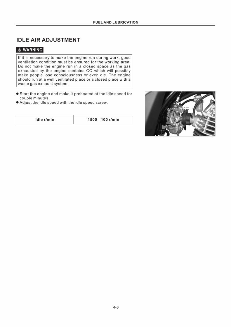
4-6
IDLE AIR ADJUSTMENT
1500 100 r/min±
FUEL AND LUBRICATION
WARNING
If it is necessary to make the engine run during work, good
ventilation condition must be ensured for the working area.
Do not make the engine run in a closed space as the gas
exhausted by the engine contains CO which will possibly
make people lose consciousness or even die. The engine
should run at a well ventilated place or a closed place with a
waste gas exhaust system.
Start the engine and make it preheated at the idle speed for
couple minutes.
Adjust the idle speed with the idle speed screw.
●
●
Idle r/min

4-7
FUEL AND LUBRICATION
LUBRICATION SYSTEM
CAMSHAFT JOURNALAND CAM FACE
ROCKER ARMSHAFT
CAM CHAIM
CONROD SMALL END
CYLINDER WALL
CONROD BIGEND BEARING
CLUTCHRELEASE CAM
DRIVESHAFTBEARING
DRIVESHAFTAND GEARS
CONTERSHAFTBEARING
COUNTERSHAFTAND GEARS
PRIMARY DRIVENGEAR SPACER
CLUTCH PLATES
OIL FILTER
OIL PUMP
SUMP FILTER
OIL PAN
CHASSIS
CONTENTS
FRONT WHEEL AND FRONT BRAKE
FRONT ABSORBER
STEERING STEM
REAR WHEEL AND REAR BRAKE
REAR SWING ARM
5-1
5-5
5-12
5-16
5-22
5

FRONT WHEEL AND FRONT BRAKE
REMOVAL AND DISASSEMBLY
CHASSIS
5-1
FRONT WHEEL
36~52N m·
6~8N m·
Support the motorcycle with the main stand.
Remove the front brake cable and the odometer flexible
shaft.
●
●
Remove the nut of front wheel shaft
Pull out the front wheel shaft, take down the front wheel and
remove the rear brake drum cover from the front wheel.
●
●

5-2
WHEEL BEARING
CHASSIS
Remove the oil seal and the front wheel bearing with proper
tools.
●
FRONT BRAKE
Remove the brake shoes.●
Unscrew the bolt and nut of the brake cam swing arm.●
Remove the brake cam, the gasket, the O-ring and the brake
cam swing arm.
●
INSPECTION
When installing the hub bearing, inspect the axial and radial
free plays of the bearing cone with hand and check whether
the bearing is making abnormal sounds or turning flexibly.
In case of any abnormal phenomena, replace the bearing with
a new one.
Play
Play
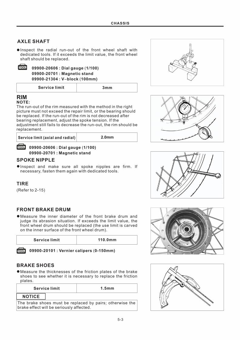
2.0mm
RIM
5-3
AXLE SHAFT
Service limit 3mm
09900-20606 : Dial gauge 1/100)
09900-20701 : Magnetic stand
09900-21304 : V block 100mm)
(
- (
110.0mm
09900-20101 : Vernier calipers 0-150mm)(
1.5mm
CHASSIS
Inspect the radial run-out of the front wheel shaft with
dedicated tools. If it exceeds the limit value, the front wheel
shaft should be replaced.
●
NOTE:The run-out of the rim measured with the method in the right
picture must not exceed the repair limit, or the bearing should
be replaced. If the run-out of the rim is not decreased after
bearing replacement, adjust the spoke tension. If the
adjustment still fails to decrease the run-out, the rim should be
replacement.
09900-20606 : Dial gauge 1/100)
09900-20701 : Magnetic stand
(
SPOKE NIPPLE
Inspect and make sure all spoke nipples are firm. If
necessary, fasten them again with dedicated tools.
●
TIRE
(Refer to 2-15)
FRONT BRAKE DRUM
Measure the inner diameter of the front brake drum and
judge its abrasion situation. If exceeds the limit value, the
front wheel drum should be replaced (the use limit is carved
on the inner surface of the front wheel drum).
●
Service limit
BRAKE SHOES
Measure the thicknesses of the friction plates of the brake
shoes to see whether it is necessary to replace the friction
plates.
●
Service limit
The brake shoes must be replaced by pairs; otherwise the
brake effect will be seriously affected.
NOTICE
Service limit (axial and radial)

5-4
ASSEMBLY
WHEEL BEARING
99000-25010 : UZUKI SUPER GREASE AS “ ”
09913-80112 : Bearing installer
BRAKE CAM
CAUTION
BRAKE CAM'S SWING ARM
Bolt for the brake cam swing arm 6~8: N m·
REASSEMBLY
CHASSIS
Reassemble the front wheel and the front brake in opposite
order of Removeing order. Meanwhile, pay attention to the
following steps.
Apply grease to the front wheel bearing before assembling
it.
●
Install the front wheel bearing with dedicated tools.●
NOTE:Install the right bearing first.
Apply proper grease to the brake cam.●
The grease applied should not be too much; otherwise slip
will happen during braking.
99000-25010 : UZUKI SUPER GREASE AS “ ”
Install the brake cam swing arm and tighten the clamping
bolt of the brake cam swing arm with the specified torque.
●
Reassembly the front wheel and the front brake in opposite
order of their disassembly and Removeing order.
●

FRONT ABSORBER
REMOVING AND DISASSEMBLY
5-5
12~20N m·
35~55N m·
25~40N m·
CHASSIS
Remove the front wheel (Refer to 5-1).●

5-6
CHASSIS
Remove the four bolts and the front fender.
Remove the screws of the steering joint cover and the
steering joint cover.
Remove the screws of the headlights, disconnect the lead
connectors and Remove the headlights.
Pull away the connectors in the headlight covers and
remove the fixing bolts of the headlight covers and the
headlight covers then.
Take apart the speedometer flexible shaft and loosen the
hoop bolt of the flexible shaft.
●
●
●
●
●

5-7
CHASSIS
Loosen the clutch adjusting nut and Remove the clutch
cable.
Loosen the throttle adjusting nut and Remove the throttle
cable.
Remove the starter cable.
Remove the four bolts and take down the handlebar stem
assembly and the permanent base.
Loosen the bolts of the front absorber and the bolts of the
steering and Remove the upper and lower plates, the
dashboard assembly and the ignition switch assembly.
●
●
●
●
●

5-8
CHASSIS
Remove the left turn light support and the right turn light
support, left turn light and the right turn light then.
Loosen the clamping bolts of the lower plate.
Pull out the left front absorber and the right front absorber.
Remove the screw plugs of the heads of the front absorber
and take out the bushes and springs of the front absorber.
Topple over the front absorber and push them a couple
times to pour the oil.
Make the front absorber upside down for 30 minutes.
●
●
●
●
●
●

5-9
CHASSIS
Remove damper rod bolt by using the special tools and 8mm
hexagon wrench.
Remove the oil lock piece and damper rod with reboumd
spring.
Separate the inner tube from the outer tube.
Remove the stopper ring.
Remove the oil seal by using the special tool.
The oil seal removed should be replaced with a new one.
INSPECTION
Inspect the damper rod ring for wear and damage.
●
WARNING
DAMPER ROD RING
●
09913-50121 Oil seal remove:
09940-34520 : T handle
09940-34561 : Attachment D
“ ”
“ ”

5-10
CHASSIS
Inspect the inner tube and outer tube sliding surfaces for
any scuffing or flaws.
INNER TUBE AND OUTER TUBE
●
Measure the fork spring free length. If it is shorter than the
service limit, replace it.
Service limit 426.3 mm
FORK SPRING
●
REASSEMBLY
Reassemble and remount the front fork in the reverse order of
disassembly and removal, and also carry out the following
steps:
THREAD LOCK CEMENTSUZUKI BOND NO.4 .Apply SUZUKI BOND No.4 and THREAD LOCK CEMENT to
the damper rod bolt and tighten the bolt by using the 8 mm
hexagon wrench .
DAMPER ROD BOLT●
No.4 99100-31030 : SUZUKI BOND NO.4
99000-32040 : THREAD LOCK CEMENT
11F14-010 : Shock absorber separating/
installer tool
09940-50112 : Oil seal installer
Install the oil seal to the outer tube by using the special tool
as shown.
OIL SEAL●

5-11
Fork oil type special absorber oil:
145mm
09943-74111 : Absorber oil level gauge
CHASSIS
106 ml
FORK OIL
Capacity ( each leg )
NOTE:When adjusting oil level, remove the absorber spring and
compress the inner tube fully.
Oil level
FORK SPRINGUpside
For the fork oil, be sure to use a front fork oil whose viscosity
rating meets specifications below.
●
Hold the front fork vertical and adjust the absorber oil level
with the special tool.
●
When installing the front fork spring, the closepitch end
should position upside.
●
REASSEMBLY
Make the absorber go through the lower bracket first and
install the left turn light support and the right turn light
support then.
Install the assembly consisting of the dashboard, the
ignition switch and the upper bracket first and pre-tighten
the bolts and nuts of the upper bracket then.
●
●
Tighten the clamping bolts of the lower bracket.●
Tightening torque : 25~40N m·
NOTE:Before fastening the lower bracket, well locate the lead bundle
hoop first.

5-12
Tightening torque : 12~20N m·
Tightening torque : 35~55N m·
A
CHASSIS
Sign
Tighten the bolts and nuts of the upper bracket of the front
absorbers with the specified torques.
●
Set the handlebars to match its punched mark to the mating
face of the holder.
Tighten the fastening bolt of the handlebar stem.
●
●
Tighten the handlebar clamping frame and make its front
spacing and rear spacing even.
Reconnect the clutch cable, the throttle cable and the
starting excess fuel cable and adjust the gap between the
clutch cable and the throttle cable (Refer to 2-8).
A
●
●
NOTE:The wiring harness and the cables should be rearranged
according to the motorcycle's wiring diagram.
Install the headlight covers and insert all connectors.
Install the headlights.
Install the handlebar stem shield.
●
●
●
Install the front fender and the front wheel.●

Upper 22
Lower 22
5-13
CHASSIS
STEERING STEMREMOVAL AND DISASSEMBLY
Remove the front wheel (Refer to 5-1).
Remove the front absorbers (Refer to 5-5).
Remove the lower steering lock nut and bearing base, the
upper steering bearing race and the lower bracket
assembly.
●
●
●
NOTE:Support the lower bracket with a hand to keep it from dropping.
When remove the lower bracket, place a piece of rag below it
to keep the balls from dropping and getting lost.
Taken out the upper balls and the lower balls.●
Number of balls
Remove the outer bearing race on the lower bracket
assembly through a chisel.
Knock out the inner bearing races at the upper and lower
ends of the frame.
●
●

5-14
CHASSIS
Upper 22
Lower 22Number of balls
INSPECTION
Inspect the Removeed parts to see whether they have the
following abnormal phenomena:
- The handlebar is deformed;
- The handlebar clamping frame is damaged;
- The bearing races are worn or corroded;
- The balls are worn or damaged; or
- The steering is deformed.
REASSEMBLY
Install the steering in opposite order of disassembly and the
Removeing order.
INNER RACES
Press both upper and lower inner races with a dedicated
tool.
●
09941-34513 : Steering race installer
OUT RACE
Press the outer race with a dedicated tool.●
09941-74910 : Sreering bearing installer
STEEL BALL
When installing the balls, apply a proper grease on both
upper and lower inner bearing races.
●
99000-25010 : SUZUKI SUPER GREASE A“ ”

5-15
CHASSIS
09940-14911
STEERING STEM NUT
Steering nutsocket wrench
NOTE:This adjustment will vary from motorcycle to motorcycle.
Tighten the steering stem nut to 40-50N m by using the
special tool.
●
Turn back the stem nut by 1/4-1/2 turn.
Turn the steering stem right ang left, lock-to-lock,five or six
time to seat the ball bearings.“ ”
●
●
WARNING
Install the upper bracket and the steering (Refer to 5-10).●
After adjustment and assembly of the upper bracket ofthe steering, shake the front wheel up and down to makesure there is no play. After that, inspect and make surethe steering is able to turn left and right freely under theaction of gravity. If the degree of play and the turnflexibility are improper, readjust the nut of the steering.
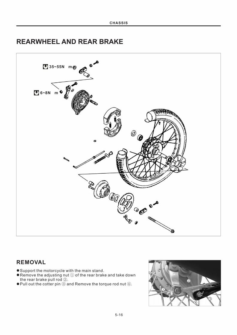
REARWHEEL AND REAR BRAKE
REMOVAL
1
2
4
3
5-16
6~8N m·
35~55N m·
CHASSIS
Support the motorcycle with the main stand.
Remove the adjusting nut of the rear brake and take down
the rear brake pull rod .
Pull out the cotter pin and Remove the torque rod nut .
①②③ ④
●
●
●
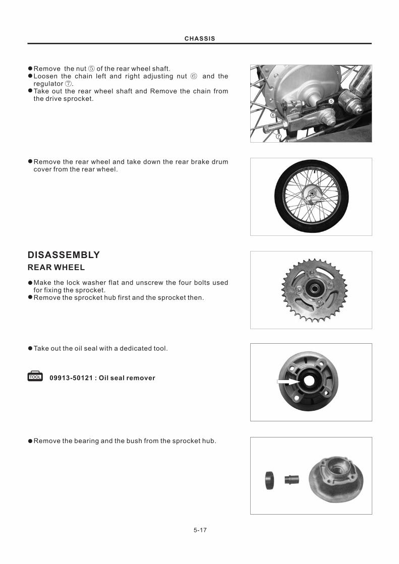
7
6
5
5-17
CHASSIS
Remove the nut of the rear wheel shaft.
Loosen the chain left and right adjusting nut and the
regulator .
Take out the rear wheel shaft and Remove the chain from
the drive sprocket.
⑤⑥
⑦
●
●
●
Remove the rear wheel and take down the rear brake drum
cover from the rear wheel.
●
DISASSEMBLY
REAR WHEEL
Make the lock washer flat and unscrew the four bolts used
for fixing the sprocket.
Remove the sprocket hub first and the sprocket then.
●
●
Take out the oil seal with a dedicated tool.●
09913-50121 : Oil seal remover
Remove the bearing and the bush from the sprocket hub.●

5-18
CHASSIS
Remove the cushion from the wheel.●
Remove the left and right bearings of the rear wheel hub.●
NOTE:It will be easier to remove the left bearing first.
REAR BRAKE
Remove the brake shoes.●
Remove the nut and bolt of the brake cam swing arm.●
Remove the brake cam, the gasket and the brake cam swing
arm.
●

��
��
5-19
CHASSIS
INSPECTION
WHEEL BEARING
As shown in the picture, inspect the free play of the rear
wheel bearing. Turn the bearing core to inspect whether the
bearing is turning flexibly and whether it is making abnormal
sound and, if it is, replace it.
●
AXLE SHAFT
Inspect the radial run-out of the rear wheel shaft with some
inspection tools. If the radial run-out exceeds the limit
value, the rear wheel shaft should be replaced.
●
Service limit 3mm
09900-20606 : Dial gauge(1/100)
09900-20701 : Magnetic stand
09900-21304 : V block-
Normal wear Excessive wear
SPROCKET
Inspect the degree of wear of the teeth of the sprocket. If
they have been seriously worn as shown in the picture, both
the sprocket and the transmission chain should be replaced.
●
REAR BRAKE DRUM
Measure the inner diameter of the rear brake drum and
judge its degree of abrasion. If the abrasion exceeds the
limit value, the rear wheel hub should be replaced (the use
limit is carved on the inner surface of the rear wheel hub).
●
110.0mmService limit
BRAKE SHOE
Measure the thicknesses of the friction plates of the brake
shoes to see whether it is necessary to replace the friction
plates.
●
1.5mmService limit
09900-20101 : Vernier calipers 0-150mm)(
WARNING
The brake shoes must be replaced by pairs; otherwisethe brake effect will be seriously affected.
Play
Play
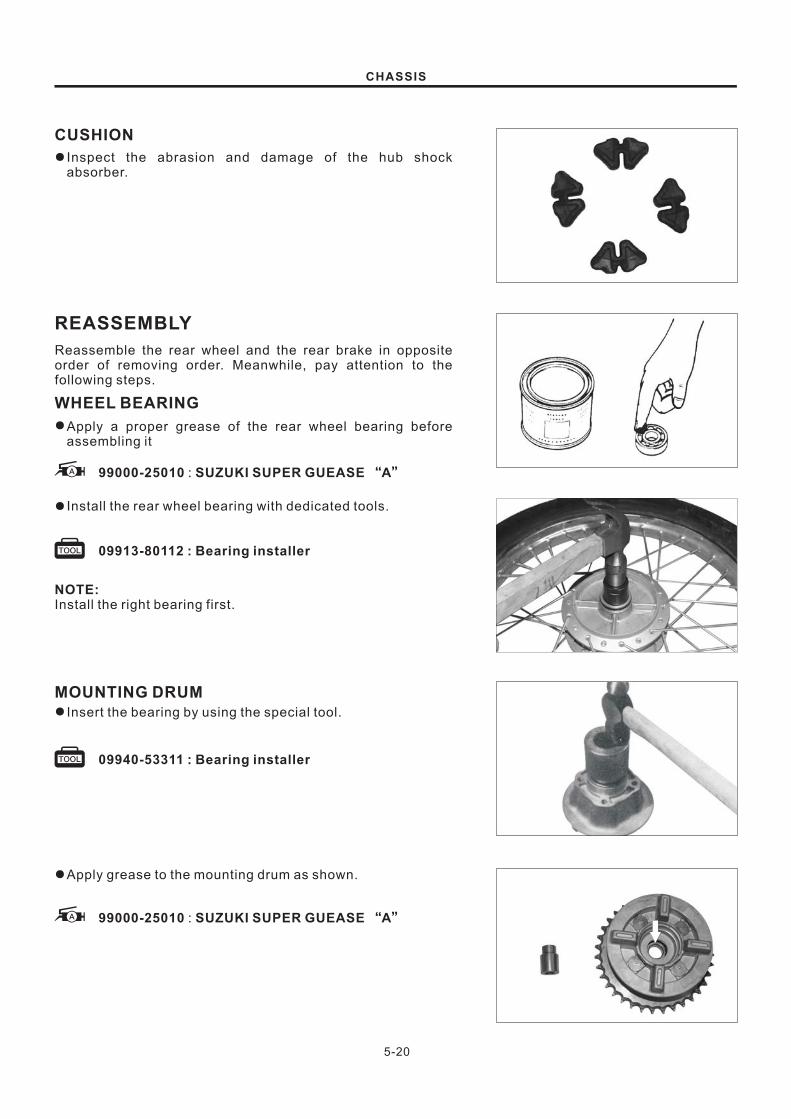
5-20
99000-25010 SUZUKI SUPER GUEASE A: “ ”
09913-80112 : Bearing installer
CHASSIS
CUSHION
Inspect the abrasion and damage of the hub shock
absorber.
●
REASSEMBLY
Reassemble the rear wheel and the rear brake in opposite
order of removing order. Meanwhile, pay attention to the
following steps.
WHEEL BEARING
Apply a proper grease of the rear wheel bearing before
assembling it
●
Install the rear wheel bearing with dedicated tools.●
NOTE:Install the right bearing first.
MOUNTING DRUM
Insert the bearing by using the special tool.●
Apply grease to the mounting drum as shown.●
99000-25010 SUZUKI SUPER GUEASE A: “ ”
09940-53311 : Bearing installer

5-21
CHASSIS
SPROCKET
Tighten the four bolts.
Make the lock washer bend toward the bolts.
●
●
BRAKE CAM
Apply a proper grease onto the brake cam.●
99000-25010 SUZUKI SUPER GUEASE A: “ ”
WARNING
The grease applied should not be too much; otherwiseslip will happen during braking.
BRAKE CAM LEVER
Install the brake cam swing arm and tighten the clamping
bolt of the brake cam swing arm with the specified torque.
●
Tightening torque : 6~8N m

REAR SWING ARM
5-22
CHASSIS
REMOVAL AND DISASSEMBLY
Remove the rear wheel (Refer to 5-16).
Remove the screws of the upper chain case first and the
chain case then.
●
●

5-23
09923-73210 : Bearing puller
09930-30102 : Rotor remover slide shaft
CHASSIS
Remove the nuts of the left and right rear absorbers first and
the rear absorber assembly then.
Remove the nut of the rear swing arm shaft, pull out the rear
swing arm shaft and Remove the rear swing arm.
Pull out the cotter pin and unscrew the bolts and the nuts.
Remove the torque rod.
Remove the cushion pad of the chain.
Take out the neck bush with dedicated tools.●
●
●
●
●
●

5-24
CHASSIS
INSPECTIONBUSHING
Inspect the abrasion of the neck bush.●
SWING ARM PIVOT SHAFT
Measure the radial run-out of the rear swing arm with a dial
indicator. If the radial run-out exceeds the limit value, the
swing arm should be replaced.
●
Service limit 0.6 mm
09900-20606 : Dial gauge(1/100)
09900-20701 : Magnetic stand
09900-21304 : V block-
REASSEMBLY
Reassemble the rear swing arm in opposite order of the
removing order. Meanwhile, pay attention to the following
steps.
Press the neck bush into the mounting hole for the neck
bush of the rear swing arm with a dedicated tool.
●
09924-84510 : Bearing installer set

ELECTRICAL
CONTENTS
IGNITION SYSTEM
CHARGING SYSTEM
COMBINATION METER
LIGHTS
SWITCHES
BATTERY
6-1
6-3
6-4
6-4
6-5
6-7
6

IGNITION SYSTEM
DESCRIPTION
MAGNETO IGNITOR
IGNITION COIL
ELECTRICAL
6-1
In a capacitor discharge ignition system, the battery supplies power for CDI components and charge the
capacitor. At a specific time of ignition, the pulse generated by the generator trigger coil triggers SCR and
makes the energy in the capacitor release via the primary coil of the ignition coil. As a result, high-voltage
current is induced on the primary coil and intense sparks are generated between the spark plug's
electrodes.
SPARK PLUG

6-2
09900-25002 : Pocket tester
99000-32050 : THREAD LOCK “1342"
0.6-0.7mm
ELECTRICAL
Using the pocket tester(RX1 range), measure the
resistance between the lead wires in the following table .
Ω
INSPECTION
PICK-UP
Charging coilresistance
L_
GApprox.120
_200Ω
Pick-up coilresistance
Y_
YApprox.0.5
_2.0Ω
NOTE:When mounting the stator on the generator cover, apply a small
quantity of THREAD LOCK "1342" to the threaded parts of
screws.
WIRE COLOR
L : Blue
G : Green
Y : Yellow
●
IGNITION COIL
Check the ignition coil with pocket tester.
09900-25002 : Pocket tester
Ignition coil resistance
Primary
Secondary
O/W -WApprox.3.5-4.5Ω
Plug cap-O/ WApprox.16-30kΩ
Clean the plug with a wire brush and pin. Use the pin to
remove carbon, taking care not to damage the porcelain.
SPARK PLUG
Check the gap with a thickness gauge.
Spark plug gap 0.6 0.7mm-
●
09900-20803 : Thickness gauge

6-3
ELECTRICAL
INSPECTION
CHARGING OUTPUT CHECK
Start the engine and keep it running at 5 000r/min. Using the
pocket tester, measure the DC voltage between the battery
terminal and .
If the tester reads under 13.5V or over 16.0V, check the AC
generator no-load performance and regulator/rectifier.
NOTE:When making this test, be sure that the battery is full-charged
condition.
STD charging output
13.5V 16.0V at 5 000r/min-
AC GENERATOR NO-LOAD PERFORMANCEDisconnect the three lead wires from the AC generator
terminal.
Start the engine and keep it running at 5 000r/min.
Using the pocket tester, measure the AC voltage between the
three lead wires.
If the tester reads under 70V, the AC generator is faulty.
STD No-load performance
More than 70V (AC) at 5 000r/min
LEAK DETECTION OF THE BATTERY
Turn the ignition switch to position “OFF”.
Remove the lead of the battery's negative pole.
As shown in the right figure, connect one end of the
multimeter on the negative terminal and the other end on the
negative pole lead. If the pointer of the milliammeter swings,
it means there is leakage of electricity.
●
●
●
Current leakage is of high likelihood. Therefore, it is
necessary to adjust the multimeter to its maximum
measuring range when an ammeter is connected.
When measuring the current, never turn the ignition switch
on position “ON”.
NOTICE
If leakage of electricity is discovered, use the connector to
find out the part where the pointer does not swing and
Remove the joints one by one.
●
09900-25002 : Pocket tester
CHARGING SYSTEM

6-4
N
SP IL 1
2
3 4
B Y O Lg
B/W
Gr
L W/Y
R/B
G/L
Y/L
ELECTRICAL
Remove the combination meter (Refer to page 5-6).
COMBINATION METER●
Using the pocket tester, check the continuity be-tween lead
wires in following diagram.
If the continuity measured is incorrect, replace the
respective part.
INSPECTION
NOTE:When making this test, it is not necessary to remove the
combination meter.
●
●
09900-25002 : Pocket tester
LIGHTS
HEADLIGHT TURN SIGNAL LIGHT
TAIL/BRAKE LIGHT
COMBINATION METER

R O
OFF
ON
①
6-5
O/Y
FRONT BRAKE LIGHT SWITCH ④
○ ○
OFF
ON
DIMMER SWITCH ⑤
Gr
○
○
O
○
○
Y/W
○
○ ○
○ ○
○ ○
O O/W
B B
Y/W YW
③
③
②
5
ELECTRICAL
Inspect each switch for continuity with the pocket tester
referring to the chart. If it is found any abnormality, replace
the respective switch as-sembly with new one.
SWITCHES
09900-25002 : Pocket tester
IGNITION SWITCH ①
4
LIGHTING SWITCH ②
ENGINE KILL SWITCH ③

TURN SIGNAL LIGHT SWITCH ①
HORN SWITCH ②
B/L B/W
○ ○
OFF
○ ○
○○
B Sb Lg
6-6
1
2
REAR BRAKE LIGHT SWITCH ④
O W/B
○ ○
OFF
ON
○○
○○
○○
○○
○○
Neutral
Low
2nd
3rd
4 ht
Y/LG/LR/BW/YLGround
④
PASSING SWITCH ③
Y O
○ ○
3
PASS
ELECTRICAL
GEAR POSITION INDICATOR LIGHT SWITCH
WIRE COLOR
Black
Brown
Green
Gray
Blue
Light green
Orange
Red
Pink
Light blue
White
Yellow
...........
..........
...........
.........
...........
.........
...........
..........
...........
.........
..........
..........
B
Br
G
Gr
L
Lg
O
R
P
Sb
W
Y
Br/R
G/L
O/W
R/B
W/B
B/W
W/Y
Y/B
Y/G
Y/L
Y/W
O/Y
Black with White tracer
Brown with Red tracer
Green with Blue tracer
Orange with White tracer
Red with Black tracer
White with Black tracer
White with Yellow tracer
Yellow with Black tracer
Yellow with Green tracer
Yellow with Blue tracer
Yellow with White tracer
Orange with yellow tracer
..........
.........
...........
.........
..........
..........
..........
..........
...........
...........
..........
..........

12N5-4B
5Ah
1.28 0.01 20 Co
0.7A
���
�
6-7
ELECTRICAL
BATTERY
SPECIFICATIONS
In fitting the battery to the motorcycle, connect the breather
tube to the battery vent.
Filling electrolyteRemove short sealed tube before filling electrolyte.
Fill battery with electrolyte (dilute sulfuric acid solution with
acid concentration of 35.0% by weight, having a specific
gravity of 1.28 at 20 C (68 F) up to indicated UPPER LEVEL.
Filling electrolyte should be always cooled below 30 C (86 F)
before filling into battery. Leave battery standing for half an
hour after filling. Add additional electrolyte if necessary.
Charge battery with current as described in the tables shown
below.
O O
O O
Type designation
Capacity
Standard electrolyte S.G.
INITIAL CHARGING
Maximum charging current
Charging time
Confirmation for date of manufacture
Servicing
The charging time for a new battery is determined by the
number of months that have elapsed since the date of
manufacture.
Date of manufacture is indicated by a three-part number ¢, as
follows. The first number indicating year, the second and the
third indicating month.
Near the end of charging period, adjust the specific gravity of
electrolyte to value specified. After charging, adjust the
electrolyte level to the UPPER LEVEL with DISTILLED
WATER.
Visually inspect the surface of the battery container. If any
signs of cracking or electrolyte leakage from the sides of the
battery have occurred, replace the battery with a new one.
If the battery terminals are found to be coated with rust or an
acidic white powdery substance, then this can be cleaned
away with sandpaper.
●

1.28 0.01 20oC
6-8
09900-28403 : Hydrometer
ELECTRICAL
Electrolyte specific gravity
Check the electrolyte level and add distilled water, as
necessary, to raise the electrolyte to each cell's UPPER
LEVEL.
Check the battery for proper charge by taking an electrolyte
S.G. Reading. If the reading is 1.22 or less, as corrected to
20 C(68 F), it means that the battery is still in a run-down
condition and needs recharging.
O O
NOTE:
First, remove the lead wire.
BASED ON S.G. READING RECHARGINGOPERATION
To correct an S.G. reading 20 C (68 F), use following table.
To read the S.G. on the hydrometer , bring the electrolyte in
the to eye level and read the graduations on the
float scale bordering on the meniscus (curved-up portion of
electrolyte surface), as shown in figure.
Check the reading (as corrected to 20 C) with chart to
determine the recharging time in hours by constant-current
charging at a charging rate of 0.8 amperes (which is a tenth of
the capacity of the present battery).
Be careful not to permit the electrolyte tempera-ture to
exceed 45 C (113 F ), at any time, during the recharging
operation. Interrupt the operation, as necessary, to let the
electro lyte cool down. Recharge the bat tery to the
specification.
O O
O
O O
hydrometer
Constant-voltage charging, otherwise called "quick"charging, is not recommendable for it could shorten thelife of the battery.Before charging the battery, take off the seal cap of eachunit. Keep the battery during charging from opening firesand sparks. When taking off the battery from themotorcycle, do take off pole first.
NOTICE
NOTE:The lead oxide applied on the battery will disappear with time
on.
If the bottom of the battery is full of deposits, the battery must
not be used any longer.
If the duration of charging of the battery is insufficient, lead
sulfate will accumulate on surfaces of the plate electrodes
and further affect the performance. In this case, the battery
should be replaced.
If the battery is not in use for a long time, sulphating will
possibly happen. If the motorcycle will not be used for over
one month (particularly in winter), the battery should be
charged once each month at least.

SERVICING INFORMATION
CONTENTS
TROUBLESHOOTING
SPECIAL TOOLS
TIGHTENING TORQUE
SERVICE DATA
WIRE AND CABLE ROUTING
WIRING DIAGRAM
7-1
7-7
7-12
7-13
7-19
7-20
7

7-1
TROUBLESHOOTINGENGINE
Complaint
Engine will not start
or is hard to start.
Engine stalls easily.
Noisy enigne.
Symptom and possible causes Remedy
Compression too low
Plug not sparking
No fuel reaching the carburetor
1. Valve clearance out of adjustment
2. Worn valve guides or poor seating of valves.
3. Valves mistiming.
4. Piston rings excessively worn.
5. Worn-down cylinder bore.
6. Poor seating of spark plug.
7. Starter motor cranks but too slowly.
1. Fouled spark plug.
2. Wet spark plug.
3. Defective pick up coil.
4. Defective ignitor unit.
5. Defective ignition coil.
6. Open or short circuit in high-tension cord.
1. Clogged hole in the fuel tank cap.
2. Clogged or defective fuel cock.
3. Defective carburetor float valve.
4. Clogged fuel pipe.
5. Clogged fuel filter.
Adjust.
Repair or replace.
Adjust.
Replace.
Replace or rebore.
Retighten.
Consult "electrical complaints"
Clean or replace.
Clean and dry.
Replace.
Replace.
Replace.
Replace.
Clean.
Clean or replace.
Replace.
Clean or replace.
Clean or replace.
1. Fouled spark plug.
2. Defective pick up coil.
3. Defective ignitor unit.
4. Clogged fuel pipe.
5. Clogged jets in carburetor.
6. Valve clearance out of adjustment.
7. Clogged fuel filter.
Clean.
Replace.
Replace.
Clean.
Clean.
Adjust.
Clean or replace.
Excessive valve chatter
Noise appears to come from piston
Noise seems to come from clutch
Noise seems to come from crankshaft
1. Valve clearance too large.
2. Weakened of broken valve springs.
3. Worn down rocker arm or rocker arm shaft.
1. Piston or cylinder worn down.
2. Combustion chamber fouled with carbon.
3. Piston pin or piston pin bore worn.
4. Piston rings or ring groove worn.
1. Worn splines of countershaft or hub.
2. Worn teeth of clutch plates.
3. Distorted clutch plates, driven and drive.
4. Clutch damper weakened.
1. Worn of burnt bearings.
2. Bjg-end bearings worn and burnt.
3. Thrust clearance too large.
Adjust.
Replace.
Replace.
Replace.
Clean.
Replace.
Replace.
Replace.
Replace.
Replace.
Replace.
Replace.
Replace.
Replace.
SERVICE INFORMATION

7-2
Complaint Symptom and possible causes Remedy
Replace.
Replace.
Replace.
Replace.
1.Clutch control out of adjustment or too much play.
2.Some clutch springs weakened while others are not.
3.Distorted pressure plate or clutch plates.
Noisy engine.
Slipping clutch.
Dragging clutch.
Transmission will not
shift.
Transmission jumps out
of gear.
Engine idles poorly.
Engine runs poorly in
high speed range.
Dirty or heavy exhaust
smoke.
Noise seems to come from transmission
1. Gears worn of rubbing.
2. Badly worn splines.
3. Primary gears worn or rubbing.
4. Badly worn bearings.
1. Clutch control out of adjustment or loss of play.
2. Weakened clutch springs.
3. Worn or distorted pressure plate.
4. Distorted clutch plates, driven and drive.
1.Broken gearshift cam.
2.Distorted gearshift forks.
3.Worn gearshift pawl.
1.Broken return spring on shift shaft.
2.Shift shafts are rubbing or sticky.
3.Distrorted or worn gearshift forks.
1.Worn shifting gears on driveshaft or countershaft.
2.Distorted or worn gearshift forks.
3.Weakened stopper pawl spring on gearshift cam.
4.Worn gearshift pawl.
1.Valve clearance out of adjustment.
2.Poor seating of valves.
3.Defective valve guides.
4.Worn rocker arm or arm shaft.
5.Defective pick up coil.
6.Defective ignitor uint.
7.Spark plug gap too wide.
8.Defective ignition coil resulting in weal sparking.
9.Clogged jets.
1.Valve springs weakened.
2.Valve timing out of adjustment.
3.Worn cams or rocker arms.
4.Spark plug gap too narrow.
5.Defective ignition coil.
6.Clogged air cleaner element.
7.Clogged fuel pipe, resulting in inadequate fuel supply to carburetor,
8.Defective pick up coil or ignitor unit.
1.Too much engine oil in the engine.
2.Worn piston rings or cylinder.
3.Worn valve guides.
4.Cylinder wall scored or scuffed.
5.Worn valves stems.
6.Defective stem seals.
7.Worn side rails.
Adjust.
Replace.
Replace.
Replace.
Adjust.
Replace.
Replace.
Replace.
Replace.
Replace.
Replace.
Repair.
Replace.
Replace.
Replace.
Replace.
Replace.
Adjust.
Replace.
Replace.
Replace
Replace.
Replace.
Adjust or replace.
replace.
Clean.
Replace.
Adjust.
Replace.
Repair.
Replace.
Clean.
Clean and prime.
Replace.
Check with inspection window,
drain out excess oil.
Replace.
Replace.
Replace.
Replace.
Replace.
Replace.
Transmission will not
shift back.
SERVICE INFORMATION

7-3
Complaint
Engine lacks power.
Engine overheats.
Symptom and possible causes Remedy
1. Loss of valve clearance.
2. Weakened valve springs.
3. Valve timing out of adjustment.
4. Worn piston ring or cylinder.
5. Poor seating of valves.
6. Fouled spark plug.
7. Worn rocker arms or its shafts.
8. Sprak plug gap incorrect.
9. Clogged jets in carburetor.
10. Clogged air cleaner element.
11. Too much engine oil.
12. Suck air intake pipe.
Adjust.
Replace.
Adjust.
Replace.
Repair.
Clean or replace.
Replace.
Adjust or replace.
Clean.
Clean.
Drain out excess oil.
Retighten or replace.
1. Heavy carbon deposit on piston crown.
2. Not enough oil in the engine.
3. Defective oil pump or clogged oil circuit.
4. Air leak from intake pipe.
5. Use of incorrect engine oil.
Clean.
Add oil.
Repair or clean.
Retighten or replace.
Change.
Complaint
Trouble with starting.
Idling or low-speed
trouble.
Medium or high-speed
trouble.
Overflow and fuel
level fluctuations.
Symptom and possible causes Remedy
Clean.
Clean.
Check starter body and carburetor
for tightness, adjust and replace
gasket.
Check and adjust.
1. Needle valve is worn or damaged.
2. Spring in needle valve is broken.
3. Float is not working properly.
4. Foreign matter has adhered to needle valve.
1.Starter jet is clogged.
2.Starter pipe is clogged.
3. Air leaking from a joint between starter body and carburetor.
4.Starter plunger is not operating properly.
Replace.
Replace.
Check and adjust.
Clean.
Check and clean.
Check and clean.
Check throttle valve for operation.
Check and clean.
CARBURETOR
1. Pilot jet, pilot air jet are clogged or loose.
2. Pilot outlet or bypass is clogged.
3. Starter plunger is not fully closed.
1. Main jet or main air jet is clogged.
2. Needle jet is clogged.
3. Throttle valve is not operating properly.
4. Filter is clogged.
Check and clean.
Check and clean.
Check and adjust.
Complaint
No sparking or poor
sparking.
Spark plug soon become
fouled with carbon.
Symptom and possible causes Remedy
Replace.
Replace.
Replace.
Adjust carburetor.
Adjust carburetor.
Change.
Clean.
Replace by hot type plug.
1. Defective ignition coil.
2. Defective spark plug.
3. Defective pick up coil or ignitor unit.
1. Mixture too rich.
2. Idling speed set too high.
3. Incorrect gasoline.
4. Dirty element in air cleaner.
5. Spark plug too cold.
ELECTRICAL
SERVICE INFORMATION

7-4
BATTERY
Complaint
Spark plug become
fouled too soon.
Spark plug electordes
overheat or burn.
Generator does not
charge.
Generator charges,but
charging rate is below
the specification.
Unstable charging.
Starter button is not
effective.
Symptom and possible causes Remedy
1.Worn piston rings.
2.Pistons or cylinder worn.
3.Excessive clearance of valve stems in valve guides.
4.Worn stem oil seals.
Replace.
Replace.
Replace.
Replace.
Replace by cold type plug.
Tune up.
Adjust.
Retighten.
Adjust carburetor.
Repair or replace or retighten.
Replace.
Replace.
Repair or retighten.
Replace.
Replace.
Add distilled water between the
level lines.
Replace the battery.
Generator overcharges.
1.Spark plug too hot.
2.The engine overheats.
3.Defective pick up coil or ignitor unit.
4.Spark plug loose.
5.Mixture too lean.
1.Open or short in lead wires, or loose lead connections.
2.Shorted, grounded or open generator coils.
3.Shorted or panctured regulator/rectifler.
1.Lead wires tend to get shorted or open-circuited
at terminals.
2.Grounded or open-circuited stator coils of generator.
3.Defective regulator/rectifier.
4.Not enough electrolyte in the battery.
5.Defective cell plates in the battery.
or loosely connected
1.Internal short-circuit in the battery.
2.Resistor element in the regulator/rectifier damaged or defective.
3.Regulator/rectifier poorly grounded.
1.Lead wire insulation frayed due to vibration,
shorting.
2.Generator internally shorted.
3.Defective regulator/rectifier.
resulting in intermittent
1.Batttery run down.
2.Defective switch contacts.
3.Brusnes not seating properly on commutator in starter motor.
4.Defective starter relay.
Replace the battery.
Replace.
Clean and tighten ground
connection.
Repair or replace.
Replace.
Replace.
Recharge or replace.
Replace.
Repair or replace.
Replace.
Complaint
"Sulfation", acidic white
powdery substance or
spots on surfaces of cell
plates.
Symptom and possible causes Remedy
Add distilled water, if the battery has not been damaged
and "sulfation" has not advanced too far, and recharge.
Replace the battery.
Replace the battery.
If "sulfation" has not advanced too far, try to restore the
battery by replacing the electrolyte, recharging it fully
with the battery detached from the motorcycle and then
adjusting electrolyte S.G.
1. Not enough electrolyte.
2.Battery caes is cracked.
3.Battery has been left in a run-down
a long time.
4.Contaminated electrolyte (Foreign matter
battery and become mixed
electrolyte.)
condition for
has
enters the with the
SERVICE INFORMATION
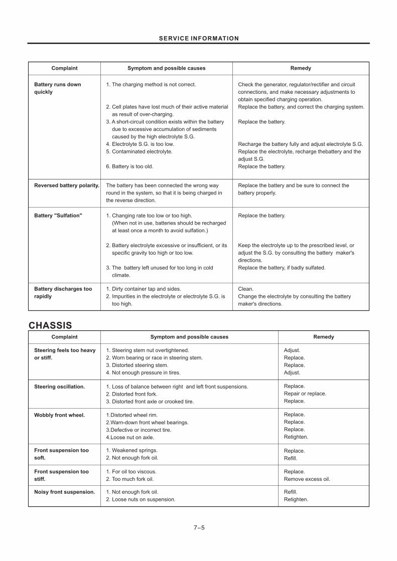
7-5
CHASSIS
Complaint
Battery runs down
quickly
Reversed battery polarity.
Battery "Sulfation"
Battery discharges too
rapidly
Symptom and possible causes Remedy
1. The charging method is not correct.
2. Cell plates have lost much of their active
result of over-charging.
3. A short-circuit condition exists within the
due to excessive accumulation of
caused by the high electrolyte S.G.
4. Electrolyte S.G. is too low.
5. Contaminated electrolyte.
6. Battery is too old.
material
as
battery
sediments
Check the generator, regulator/rectifier and circuit
connections, and make necessary adjustments to
obtain specified charging operation.
Replace the battery, and correct the charging system.
Replace the battery.
Recharge the battery fully and adjust electrolyte S.G.
Replace the electrolyte, recharge thebattery and the
adjust S.G.
Replace the battery.
The battery has been connected the wrong way
round in the system, so that it is being charged in
the reverse direction.
1. Changing rate too low or too high.
(When not in use, batteries should be
least once a month to avoid
2. Battery electrolyte excessive or insuffi
specific gravity too high or
3. The battery left unused for too long in cold
climate.
recharged
at sulfation.)
cient, or its
too low.
1. Dirty container tap and sides.
2. Impurities in the electrolyte or elec
too high.
trolyte S.G. is
Replace the battery and be sure to connect the
battery properly.
Replace the battery.
Keep the electrolyte up to the prescribed level, or
adjust the S.G. by consulting the battery maker's
directions.
Replace the battery, if badly sulfated.
Clean.
Change the electrolyte by consulting the battery
maker's directions.
Complaint
Steering feels too heavy
or stiff.
Steering oscillation.
Wobbly front wheel.
Front suspension too
stiff.
Front suspension too
soft.
Noisy front suspension.
Symptom and possible causes Remedy
1. Steering stem nut vertightened.
2. Worn bearing or race in steering stem.
3. Distorted steering stem.
4. Not enough pressure in tires.
o
1. Loss of balance between right and left front suspensions.
2. Distorted front fork.
3. Distorted front axle or crooked tire.
Adjust.
Replace.
Replace.
Adjust.
Replace.
Repair or replace.
Replace.
1.Distorted wheel rim.
2.Warn-down front wheel bearings.
3.Defective or incorrect tire.
4.Loose nut on axle.
1. Weakened springs.
2. Not enough fork oil.
1. For oil too viscous.
2. Too much fork oil.
1. Not enough fork oil.
2. Loose nuts on suspension.
Replace.
Replace.
Replace.
Retighten.
Replace.
Refill.
Replace.
Remove excess oil.
Refill.
Retighten.
SERVICE INFORMATION

7-6
Complaint
Wobbly rear wheel.
Rear suspension too
soft.
Rear suspension too
stiff.
Noisy rear suspension.
Symptom and possible causes Remedy
1. Distorted wheel rim.
2. Worn-down rear wheel bearings.
3. Defective or incorrect tire.
4. Loose nut on axle.
5. Worn swing arm bushings.
6. Loosen nuts on the rear shock.
Remedy
Replace.
Replace.
Retighten.
Replace.
Retighten.
1. Weakened springs.
2. Rear suspension adjuster improperly set.
1. Rear suspension adjuster improperly set.
2. Warn swing arm bushings.
1. Loose nuts on suspension.
2. Worn swing arm bushings.
Replace.
Adjust.
Adjust.
Replace.
Retighten.
Replace.
BRAKES
Complaint
Poor braking.
Insufficient brake power.
Brake squeaking.
Excessive brake lever
stoke.
Leakage of brake fluid.
Symptom and possible causes Remedy
1. Not enough brake fluid in the reservoir.
2. Air trapped in brae fluid circuit.
3. Pads worn down.
4. Top much play on brake lever or pedal.
5. Linings worn down.
Refill to level mark.
Bleed air out.
Replace.
Adjust.
Replace.
1. Leakage of brake fluid from hydraulic system.
2. Worn pads.
3. Oil adhesion on engaging surface of pads.
4. Worn disc.
5. Air in hydraulic system.
1.Carbon adhesion on pad surface.
2.Tilted pad.
3.Damaged wheel bearing.
4.Loose front-wheel axle or rear-wheel axle.
5.Worn pads.
6.Foreign material in brake fluid.
7.Clogged return port of matter cylinder
1.Air in hydraulic system.
2.Warn brake lever cam.
3.Insufficient brake fluid.
4.Improper quality of brake fluid.
1.Insufficlent tightening of connection joints.
2.Cracked hose.
3.Worn piston and/or cup.
Repair or replace.
Replace.
Clean disc and park
Replace
Bleed air
Repair surface with sandpaper.
Modify pad fitting.
Replace.
Tighten to specified torque.
Replace.
Replace brake fluid.
Disassemble and clean master
cylinder.
Bleed air.
Replace brake lever.
Replenish fluid to specified lever;
bleed air.
Replace with correct fluid.
Tighten to specified torque.
Replace.
Replace piston and/or cup.
SERVICE INFORMATION

7-7
1
2
3
4
5
6
7
8
9
10
11
12
13
14
15
16
17
18
19
20
21
22
23
24
25
26
27
28
29
30
31
32
33
34
35
36
37
38
39
SPECIAL TOOLS
ITEM PART NO. PART NAME
09900-06107
09900-06108
09900-09003
09900-20101
09900-20202
09900-20203
09900-20205
09900-20508
09900-20606
09900-20701
09900-20803
09900-21304
09900-25002
09900-28106
09900-28403
11F14-1019
09910-32812
09910-34510
09911-73730
09913-50121
09913-75820
09913-80112
09915-63310
09915-64510
09915-74510
11F14-018
09916-21110
09916-24311
09916-24610
09916-20620
09916-20630
09916-34542
09916-34570
09916-34580
11F14-012
11F14-011
11F14-019
11F14-002
11F14-009
09923-73210
09924-84510
09930-30102
Snap ring pliers (opening type)
Snap ring pliers (closing type)
Impact driver set
Vernier calipers (150 mm)
Micrometer (25 50 mm)
Micrometer (50 75 mm)
Micrometer (0 25 mm)
Cylinder gauge set
Dial gauge (1/100)
Magnetic stand
Thickness gauge
V-block
Pocket tester
Electro tester
Hydrometer
Conrod holder
Crankshaft installer
Piston pin puller
"T" type hexagon wrench (5 mm)
Oil seal remover
Bearing installer
Bearing installer
Compression pressure adapter
Compression gauge
Oil pressure gauge
Valve spring knocked-down tool
Valve seat cutter set
Solid pilot (N-100-5.0)
Valve seat cutter 15 (N-121)
Reamer handle
5.0mm reamer
10.8 mm reamer
Clutch stem nut socket wrench
Valve adjust tool
Crankcase separating tool/crankshaft remover
Clutch sleeve hub holder
Bearing puller
Bearing installer set
Rotor remover slide shaft
-
-
-
O
Valve seat cutter 45 (N-122)
Valve seat cutter 30 (N-126)
Clutch stem nut socket wrench
O
O
SERVICE INFORMATION

7-8
ITEM PART NO. PART NAME
11F14-004
11F14-005
09940-14911
11F14-010
11F14-003
09940-50112
09940-53311
09941-34513
09943-74111
11F14-001
11F14-007
11F14-008
Rotor
Steering stem nut socket wrench
Shock absorber separating/installer tool
bolt
Fork oil seal installer
Bearing installer
Steering race installer
Fork oil level gauge
Rotor holder
Finally driven gear separating tooll
separator
Rotor and sprocket holder
Rotor separator
Rotor separator
40
41
42
43
44
45
46
47
48
49
50
51
1
7
4
2
8
5
3
9
6
SERVICE INFORMATION

7-9
10
13
11
14
12
15
16
21
18
22
19
17
23
20
24
SERVICE INFORMATION

7-10
2725
28
26
29 30
37
3331
38
34 35
32
39
36
SERVICE INFORMATION
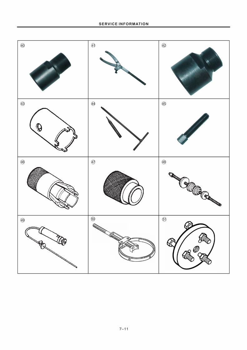
7-11
40
43
41
44 45
46
49
47 48
42
SERVICE INFORMATION
50 51

TIGHTENING TORQUE
ENGINE
N mKg mITEM
Cylinder head nut
Cylinder head side bolt
Bolts of the air hose
Nut on the generator rotor
Bolts on the starting clutch hub
Adjusting nut for valve clearance
Nut on the clutch hub
Mounting bolt for the engine (front)
Mounting bolt for the engine (rear)
Mounting bolt for the engine (top)
2.3-2.7
0.8-1.2
0.8-1.2
5.0-7.0
1.9-2.3
0.9-1.1
4.0-6.0
3.3-3.9
3.3-3.9
3.3-3.9
23-27
8-12
8-12
50-70
19-23
9-11
40-60
33-39
33-39
33-39
Front axle nut
Bolts on the upper bracket
Bolts on the lower bracket
(clamping bolts of the front absorbers)
Clamping bolt on the handle pipe
Bolt on the muffler cylinder head
Bolt/nut on the overhang of the engine
(top and front)
Nuts on the rear absorbers
(upper and lower)
Nut on the rear axle
Bolt/nut on the swing arm of the shift cam
(front and rear)
Nut of side bracket installer
Bolt/nut on the rear swing arm
3.6-5.2
3.5-5.5
2.5-4.0
1.2-2.0
2.0-2.4
2.2-3.3
2.2-3.5
3.5-5.5
0.6-0.8
3.0-5.0
4.5-7.0
36-52
35-55
25-40
12-20
20-24
22-33
22-35
35-55
6-8
30-50
45-70
CHASSIS
7-12
N mKg mITEM
SERVICE INFORMATION

Unit mm:
ITEM
Valve diam
Valve clearance (when cold)
Valve guide to valve stem
clearance
Valve guide I.D.
Valve stem O.D.
Valve stem runout
Valve stem deflection
Valve head thickness
Valve seat width
Valve spring free length
IN
EX
IN
EX
IN
EX
IN&EX
IN
EX
IN&EX
IN&EX
IN&EX
IN&EX
IN
EX
Compression pressure
Cylinder head distortion
24
22
——
——
0.9-1.1
——
——
10-14kg/cm²
——
——
——
——
——
——
——
——
——
0.05
STANDARD LIMIT
7-13
8kg/cm²
——
0.03-0.08
0.08-0.13
——
——
TIGHTENING TORQUE CHARTFor other bolt and nuts who's torque is not listed, refer to this chart:
Bolt Diameter
(mm)
Conventional or "4" marked bolt "7" marked bolt
4
5
6
8
10
12
14
16
18
kg m
0.15-0.3
0.3-0.6
0.8-1.2
1.8-2.8
4.0-6.0
7.0-10.0
11.0-16.0
17.0-25.0
20.0-28.0
kg m
0.1-0.2
0.2-0.4
0.4-0.7
1.0-1.6
2.2-3.5
3.5-5.5
5.0-8.0
8.0-13.0
13.0-19.0
N m
1.0-2.0
2.0-4.0
4.0-7.0
10.0-16.0
22.0-35.0
35.0-55.0
50.0-80.0
80.0-130.0
130.0-190.0
N m
1.5-3.0
3.0-6.0
8.0-12.0
18.0-28.0
40.0-60.0
70.0-100.0
110.0-160.0
170.0-250.0
200.0-280.0
Conventional bolt "4" marked bolt "7" marked bolt
A
CYLINDER + VALVE
SERVICE DATA
0.010-0.037
0.030-0.057
5.000-5.012
4.975-4.990
4.955-4.970
0.05
0.35
0.03
34.2
34.2
SERVICE INFORMATION

ITEM STANDARD LIMIT
27.84-27.94
——
27.54
0.10
Cam height
Camshaft runout
CAMSHAFT Unit mm:
7-14
IN
EX 27.65-27.75 27.35
Rocker arm I.D.
Rocker arm shaft O.D.
——
——
Piston ring end gap
51.000-51.015
——
1st ——
2nd ——
0.002-0.014
51.135
50.840
0.05
0.50
0.50
0.180
0.180
——
——
——
Cylinder bore
Piston diam
Cylinder distortio
Oil ring
1.01-1.03
1.01-1.03
2.01-2.03
0.97-0.99
0.97-0.99
——
——
——
——
——
10.003-10.018
9.981-10.018
Unit mm:CYLINDER + PISTON + PISTON RING
ITEM STANDARD LIMIT
50.965-50.980 (Measure at 10 mm from the skirt end)
1st
2nd
1st
2nd
1st
2nd
14.002-14.008
13.996-14.000
14.038
13.976
Piston ring groove clearance
Piston ring groove width
Piston ring thickness
Piston pin bore
Piston pin O.D.
Piston to pin clearance
SERVICE INFORMATION

TRANSMISSION + DRIVE CHAIN
3.667(77/21)
2.714(35/14)
3.000(33/11)
1.923(25/13)
1.375(22/16)
1.053(20/19)
4.3-4.4 mm
Type
Links
20-pitch length
KMC 428H
104
——
10-20 mm
——
——
——
——
——
——
——
——
——
259.0 mm
——
7-15
——
41.9-42.1mm
14.064mm
3.0mm
——
0.05mm——
——
14.006-14.024mm
16.995-17.000mm
CONROD + CRANKSHAFT
CLUTCH
4
2.90 3.10-
——
——
——
2.6
0.10
35.28
11.011.8-12.0
Unit mm:
ITEM STANDARD LIMIT
Conrod small end I.D.
Conrod deflection
Conrod big end width
Crankshaft web to web width
Crankshaft runout
Unit mm:
ITEM STANDARD LIMIT
Clutch cable play
Drive plate thickness
Drive plate claw width
Driven plate distortion
Clutch spring free length
Unit mm:
ITEM STANDARD LIMIT
Primary reduction ratio
Final reduction ratio
Gear ratio
Low
2nd
3rd
4th
Shift fork thickness
Drive chain
Drive chain slack
SERVICE INFORMATION

ELECTRICAL
ITEM SPECIFICATION NOTE
Over 8mm at 1atm
NGK CR6HSA
0.6mm-0.7mm
0.2-0.4Ω
4.0 6.5K- Ω
12N5-4B
5Ah
1.28 0.01 (20oC)
15A
35W
35W
5/21W
10W
5W
2W
3W
2W
2W
2W
7-16
WATTAGE
CARBURETOR
Carburetor type
Bore size
I.D.No.
Idle r/min
Main jet M,J( )
MIKUNI
22mm
36H1
1500 100
#106.3
Needle jet N,J( )
Pilot jet P,J( )
Pilot screw P,S( )
Jet needle J,N( )
Throttle cable play
E-3M
#15
PRE-SET (1 3/4turn out),
4DN29
0.5-1.0mm
ITEM SPECIFICATION ITEM SPECIFICATION
Ignition timing
Spark plugType
Gap
Spark performance
Ignition coil resistancePrimary
Secondary
Generator no-load voltage More than 70V (AC) at 5000 r/min
Battery
Fuse
13.5 16.0V at 5 000 r/min-Regulated voltage
Type designation
Capacity
Standard electrolyte S.G.
15 B.T.D.C. below 1 500 r/mim
55 B.T.D.C. above 4 000 r/min
O
O
Plug cap B/W-
W B/W-
ITEM ITEM SPECIFICATIONSPECIFICATION
HeadlightHI
LO
Taillight/brake light
Turn light
Position light
Neutral indicator light
Speedometer light
High-beam indicator light
Turn signal indicator light
Gear indicator light
SERVICE INFORMATION

ITEM STANDARD LIMIT
BRAKE + WHEEL
20-30mm
8mm
2.50-17 38L
2.75-17 41P
——
——
——
——
——
——
——
110.0mm
2.0mm
2.0mm
0.25mm
0.25mm
——
——
Unit mm:
NOTE
100
145
——
——
7-17
435 426.3
211
——
——
0.3
32# Fork oil ——
Front
Rear
Front
Rear
Front
Rear
Rear brake pedal free travel
Rear brake pedal height
Brake drum I.D.
Wheel rim runout
Wheel axle runout
Tire size
kpa
175
200
kpa
175
225
kg/cm
1.75
2.00
2kg/cm
1.75
2.25
2psi
25
29
psi
25
53
TIRE PRESSURE
COLD INFLATIONTIRE PRESSURE
NORMAL RIDING
SOLO RIDING DUAL RIDING
FRONT
REAR
SUSPENSION
ITEM STANDARD LIMIT
(Front absorber) stroke
Front absorber springfree length
Front absorber oil level
Front absorber oil type
Rear absorber springfree lengthSwingarm pivot shaftrunout
SERVICE INFORMATION

FUEL + OIL
ITEM NOTESPECIFICATION
9.2L
1.8L
SAE10W/40,API SF orSG
0.9L
106ml
SERVICE INFORMATION
7-18
1.0L
1.1L
Use gasoline with an octane number of 90-97(Research Method), preferably unleaded.
Fuse type
Fuel tank
Engine oil type and grade
Engine oilcapacity
Front shock absorber oilcapacity (each leg)
Including reserve
Reserve
Change
Filter change
Overhaul
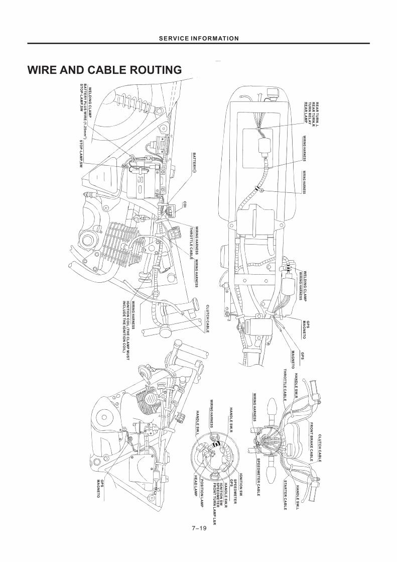
WIRE AND CABLE ROUTING
7-19
SERVICE INFORMATION
RE
AR
TU
RN
,LR
EA
RT
UR
N,R
TU
RN
RE
LA
YR
EA
RL
AM
PW
IRIN
GH
AR
NE
SS
WIR
ING
HA
RN
ES
SW
IRIN
GH
AR
NE
SS
WE
LD
ING
CL
AM
PG
PS
GP
SM
AG
NE
TO
MA
GN
ET
OH
AN
DL
ES
W,R
TH
RO
TT
LE
CA
BL
E
FR
ON
TB
RA
KE
CA
BL
E
CL
UT
CH
CA
BL
E
HA
ND
LE
SW
,L
ST
AR
TE
RC
AB
LE
WIR
ING
HA
RN
ES
SS
PE
ED
ME
TE
RC
AB
LE
HA
ND
LE
SW
,R
WIR
ING
HA
RN
ES
S
HA
ND
LE
SW
,L
IGN
ITIO
NS
W
SP
EE
DM
ET
ER
GP
SFR
ON
TT
UR
NL
AM
PL
&R
PO
SIT
ION
LA
MP
HE
AD
LA
MP
HA
ND
LE
SW
,R
IGN
ITIO
NS
WS
PE
ED
ME
TE
R
GP
SM
AG
NE
TO
CL
UT
CH
CA
BL
E
WIR
ING
HA
RN
ES
S
IGN
ITIO
NC
OIL
(TH
EC
LA
MP
MU
ST
INC
LU
DE
TH
EIG
NIT
ION
CO
IL)
WIR
ING
HA
RN
ES
SW
IRIN
GH
AR
NE
SS
TH
RO
TT
LE
CA
BL
E
CD
I
BA
TT
ER
Y
ST
OP
-LA
MP
,SW
BA
TT
ER
YP
LU
SW
IRE
(1.2
5m
m)
2
ST
OP
-LA
MP
,SW
WE
LD
ING
CL
AM
P

WIRING DIAGRAM
7-20
SERVICE INFORMATION
N
SP
IL123
4
ON
OF
FO
N
OF
F
OW
B
BL
+-
-
+
12
V
OF
F
ON
OY
O1
K1
/4W
R
PA
SS
N1234
15
A
WB/W
Y
WB/W
Y
B/W
B/W
Br
Gr
BB
B/W
B/W
B/W
Lg
Lg
B/W
B/W
Lg
Lg
W/B
W/B
B/W
B/W
Gr
Br
BB/W
BB/W
B B
Y Y
O O
Lg Lg
B/W B/W
Gr Gr
L/B L
W/Y W/Y
R/B R/B
G/L G/L
Y/L Y/L
Y/W
O
Gr
O
Gr
O/W O/W
W/B B
O O/B
B
B
B/W
W
W
L
O/Y
B/W
O/W
O
Y
Y
B/W
R
O O
W/B W/B
O
Sb
R
R
B/W
L L/B
W/Y W/Y
R/B R/B
G/L G/L
Y/L Y/L
G B/W
L L
B Y
B Y
Y/W Y/W
W W
Y Y
B/L B/L
B/W B/W
Lg Lg
Sb Sb
B B
O O
B
BL
O/Y O/Y
R R
O O
R�
�
SP
EE
DM
ET
ER
HA
ND
LE
SW
,R
LIG
HT
SE
NG
INE
SH
OP
F-B
RA
KE
SW
IGN
ITIO
NC
OIL
CD
I
RE
G&
RE
CS
TO
P-L
AM
P,S
WT
UR
N-R
EP
LY
RE
AR
-TU
RN
,R
RE
AR
-CO
MB
,LA
MP
RE
AR
-TU
RN
,L
FU
SE
BA
TT
ER
Y
MA
GN
ET
OG
PS
PA
SS
ING
,S
WT
UR
N,
SW
HA
ND
LE
SW
,L
HO
RN
SW
HO
RN
IGN
ITIO
NS
W
IMM
ER
HE
AD
-LA
MP
PIS
TO
NL
AM
P
FR
ON
T-T
UR
N,
L
FR
ON
T-T
UR
N,
R
IG. COIL
CRANK ANGLE SIGNAL
IGNITION SWITCH SIGNAL
EARTH
IGNITION SIGNAL
WIR
EC
OL
OR
Bla
ck
Bro
wn
Gre
en
Gra
y
Blu
e
Lig
htg
re
en
...........
..........
...........
.........
...........
.........
BBr
GGr
LLg
ORPSb
WY
Ora
ng
e
Re
d
Pin
k
Lig
htb
lue
Wh
ite
Ye
llow
...........
..........
...........
.........
..........
..........
Br/R
G/B
l
O/W
R/B
W/B
B/W
Bla
ck
with
Wh
itetr
ace
r
Bro
wn
with
Re
dtr
ace
r
Gre
en
with
Blu
etr
ace
r
Ora
ng
ew
ithW
hite
tra
ce
r
Re
dw
ithB
lack
tra
ce
r
Wh
itew
ithB
lack
tra
ce
r
..........
.........
...........
.........
..........
..........
W/Y
Y/B
Y/G
Y/L
Y/W
O/Y
..........
..........
...........
...........
..........
.......... Wh
itew
ithY
ello
wtr
ace
r
Ye
llow
with
Bla
ck
tra
ce
r
Ye
llow
with
Gre
en
tra
ce
r
Ye
llow
with
Blu
etr
ace
r
Ye
llow
with
Wh
itetr
ace
r
Ora
ng
ew
ithY
ello
wtr
ace
r

SE
RV
IC
EM
AN
UA
LG
110
D
SERVICE MANUAL
JIANGMENDACHANGJIANGGROUP.,LTD.
Address:No.5,JiandabeiRoad,JiangmenCity,GuangdongProviceP.R.CTelephone:86-750-3288999 Fax:86-750-3288333 Postcode:529000