G-422-P03 - Hewalex.pl · USER’S MANUAL OF AN INDEPENDENT REGULATION BLOCK G-422-P03 Controller...
18
USER’S MANUAL OF AN INDEPENDENT REGULATION BLOCK G-422-P03 Controller of a solar collector system version 0.1a
Transcript of G-422-P03 - Hewalex.pl · USER’S MANUAL OF AN INDEPENDENT REGULATION BLOCK G-422-P03 Controller...
USER’S MANUAL OF AN INDEPENDENT REGULATION BLOCK
G-422-P03
Controller of a solar collector system
version 0.1a
HEWALEX 01.08.2011 2 / 18
Table of Content
1. CONTROLLER DESCRIPTION .................................................................................................................... 3
2. CONNECTING EXTERNAL DEVICES ......................................................................................................... 3
3. USING THE CONTROLLER ......................................................................................................................... 4
3.1 Switching the controller on ................................................................................................................................................................. 4
3.2 Installation scheme selection ............................................................................................................................................................. 4
3.3 Editing and setting control parameters ............................................................................................................................................... 5
3.4 Setting operating hours for C and K external devices (available for schemes, in which C and K external devices are connected) ...... 6
3.5 Setting date and time ......................................................................................................................................................................... 6
3.6 Manual control of external devices connected to the controller (scheme 8 as an example). ............................................................... 7
3.7 Energy and power statistics ............................................................................................................................................................... 7
4. DESCRIPTION OF PARAMETER SETTINGS ............................................................................................. 8
4.1 Control parameters ............................................................................................................................................................................ 8
5. CALCULATING INSTANTANEOUS POWER AND THERMAL ENERGY .................................................... 9
6. REMAINING CONTROLLER OPTIONS ....................................................................................................... 9
6.1 Controller settings .............................................................................................................................................................................. 9
6.2 Cooling function – available only for installations with flat solar collectors .......................................................................................... 9
6.3 Holiday settings – available for specific schemes only ........................................................................................................................ 9
6.4 Default settings ................................................................................................................................................................................ 10
7. INSTALLATION SCHEMES DESCRIPTION .............................................................................................. 10
7.1 Tap water heating – controlling P solar pump – scheme no.1 ........................................................................................................... 10
7.2 Tap water heating – controlling P solar pump and circulation pump – scheme no. 2 ........................................................................ 10
7.3 Tap water heating – controlling P solar pump, circulation pump and K external device (boiler) – scheme no. 3................................ 10
7.4 Tap water heating – controlling P solar pump, circulation pump and K external device (electric heater) – scheme no. 4 .................. 11
7.5 Tap water heating – controlling P solar pump, circulation pump and K external device (heat pump) – scheme no. 5........................ 12
7.6 Tap water heating – controlling P solar pump, circulation pump and pump of K external device (solid-fuel burner) – scheme no. 6 . 12
7.7 Two water heater system – reheating a burner water heater with surplus energy from the solar water heater by use of a mixing pump (K) .......................................................................................................................................................................................... 13
7.8 Two water heater system – reheating a burner water heater with surplus energy from the solar water heater by use of circulation return ............................................................................................................................................................................................... 13
7.9 Tap water heating and swimming pool heating by use of the three-way valve, controlling the pool water pump – scheme no. 9 ...... 14
7.10 Tap water heating and swimming pool heating by use of additional pump, controlling the pool water pump – scheme no. 10 ........ 14
7.11 Two water heater system – heating with a use of the three-way valve and circulation pump – scheme no. 11. ................................ 15
7.12 Two water heater system – heating with a use of an additional pump and circulation pump – scheme no. 12. ................................. 15
7.13 Central heating system – solar collectors combined with a buffer tank to support central heating – scheme no. 13. ......................... 15
7.14 Heating a combi heater (tap water + central heating) with a use of electric, liquid fuel and solid fuel heat sources. .......................... 16
7.15 Tap water heating – controlling solar pumps for collectors positioned on different roof planes.......................................................... 16
7.16 Two water heater system – heating with the use of three-way valve and solar collector pumps positioned on different roof planes . 17
7.17 Tap water heating – controlling solar pump, circulation pump and heater cooling system – scheme no. 17 ...................................... 17
8. SENSORS ERROR ALARMS ..................................................................................................................... 17
9. INFORMATION REGARDING LABELING AND DISPOSAL OF WASTE ELECTRIC AND ELECTRONIC EQUIPMENT ............................................................................................................................................... 18
HEWALEX 01.08.2011 3 / 18
1. Controller description
G422-P03 Controller is a device designed and produced to be used with solar collector installations. This product has been created on the basis of a faultless modern microchip technology. The controller has a modern look and is very easy to use, thanks to its user panel which features a simple keyboard and an LCD screen. A powerful feature of the controller is its extended packet of basic options, which significantly increases its functionality. These include:
A selection of many different installation configurations (schemes)
Installation diagrams with animated symbols representing operating devices
Regulation of the solar system pump speed
Possibility of manual control of all devices connected to the controller
Calculating instantaneous power output and cumulative energy yield of solar installation within a given time frame
Built-in real-time clock
Storage of controller settings after disconnecting it from a power supply source
Protection modes preventing from freezing or overheating the installation
Possibility of night cooling or holiday settings
LCD screen saving mode to decrease electricity consumption
Additionally, a number of functions improving the use of the controller have been introduced:
Intuitive menu
Graphic representation of time periods
Availability of many different language versions
Easy and quick configuration of parameters settings
2. Connecting external devices
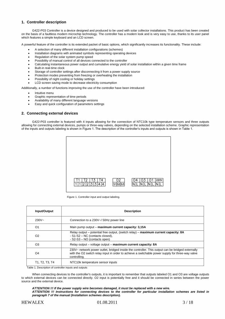
G422-P03 controller is featured with 4 inputs allowing for the connection of NTC10k type temperature sensors and three outputs allowing for connecting external devices, pumps or three-way valves, depending on the selected installation scheme. Graphic representation of the inputs and outputs labeling is shown in Figure 1. The description of the controller’s inputs and outputs is shown in Table 1.
Figure 1. Controller input and output labeling.
Input/Output Description
230V~ Connection to a 230V~/ 50Hz power line
O1 Main pump output – maximum current capacity: 3,15A
O2 Relay output – potential free output, (switch relay) – maximum current capacity: 8A - S1-S2 – NC (contacts closed), - S2-S3 – NO (contacts open)
O3 Relay output – voltage output – maximum current capacity: 8A
O4 230V~ network power outlet, bridged inside the controller. This output can be bridged externally with the O2 switch relay input in order to achieve a switchable power supply for three-way valve controlling.
T1, T2, T3, T4 NTC10k temperature sensor inputs
Table 1. Description of controller inputs and outputs
When connecting devices to the controller's outputs, it is important to remember that outputs labeled O1 and O3 are voltage outputs
to which external devices can be connected directly. O2 input is potentially free and it should be connected in series between the power source and the external device.
ATTENTION !!! If the power supply wire becomes damaged, it must be replaced with a new wire. ATTENTION !!! Instructions for connecting devices to the controller for particular installation schemes are listed in paragraph 7 of the manual (Installation schemes description).
HEWALEX 01.08.2011 4 / 18
3. Using the controller
3.1 Switching the controller on
After connecting the controller to the power source, it is operating in a standby mode. The diode is solid green, the LCD screen is
half-lit and it shows the current version of the controller. The controller can be switched on by pressing button. During its regular
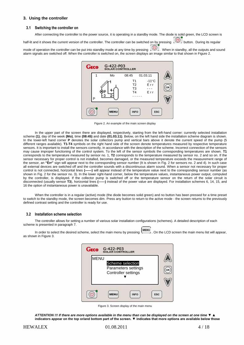
mode of operation the controller can be put into standby mode at any time by pressing . When in standby, all the outputs and sound alarm signals are switched off. When the controller is switched on, the screen displays an image similar to that shown in Figure 2.
Figure 2. An example of the main screen display
In the upper part of the screen there are displayed, respectively, starting from the left-hand corner: currently selected installation scheme (1), day of the week (Mo), time (08:45) and date (01.03.11). Below, on the left hand side the installation scheme diagram is shown. In the lower-left hand corner P denotes the solar collectors pump and vertical bars above it denote the current speed of the pump (5 different ranges available). T1-T4 symbols on the right hand side of the screen denote temperatures measured by respective temperature sensors. It is important to install the sensors correctly, in accordance with the description of the scheme. Incorrect connection of the sensors may cause improper functioning of the control system. To the left of the sensor symbols the corresponding temperatures are shown. T1 corresponds to the temperature measured by sensor no. 1, T2 corresponds to the temperature measured by sensor no. 2 and so on. If the sensor necessary for proper control is not installed, becomes damaged, or the measured temperature exceeds the measurement range of the sensor, an “Err” sign will appear next to the corresponding sensor number (It is shown in Fig. 2 for sensors no. 2 and 4). In such case all external devices are switched off and the controller sounds with a discontinuous alarm sound. When a sensor not necessary for proper control is not connected, horizontal lines (------) will appear instead of the temperature value next to the corresponding sensor number (as shown in Fig. 2 for the sensor no. 3). In the lower right-hand corner, below the temperature values, instantaneous power output, computed by the controller, is displayed. If the collector pump is switched off or the temperature sensor on the return of the solar circuit is disconnected (usually sensor T3), horizontal lines (------) instead of the power value are displayed. For installation schemes 6, 14, 15, and 16 the option of instantaneous power is unavailable.
When the controller is in a regular (active) mode (the diode becomes solid green) and no button has been pressed for a time preset to switch to the standby mode, the screen becomes dim. Press any button to return to the active mode - the screen returns to the previously defined contrast setting and the controller is ready for use.
3.2 Installation scheme selection
The controller allows for setting a number of various solar installation configurations (schemes). A detailed description of each scheme is presented in paragraph 7.
In order to select the desired scheme, select the main menu by pressing . On the LCD screen the main menu list will appear, as shown in Figure 3.
Figure 3. Screen display of the main menu
ATTENTION !!! If there are more options available in the menu than can be displayed on the screen at one time ▼ ▲ indicators appear on the top or/and bottom part of the screen. ▼ indicates that more options are available below those
P
T1 -11C T2 E r r T3 - - - T4 E r r - - - - -
1 Mo 08:45 01.03.11
MENU Scheme selection Parameters settings Controller settings
▼

HEWALEX 01.08.2011 5 / 18
currently shown on the screen and they can be accessed by pressing . ▲ indicates that more options are available
above those currently shown on the screen and they can be accessed by pressing .
Next, using or buttons select Scheme selection and press . After entering the scheme selection menu, the diagram of the scheme is displayed on the screen together with the scheme number, as shown in Figure 4.
Figure 4. Screen display when selecting a desired scheme configuration.
By using or select the desired scheme and confirm it with . The selected setting is saved and the screen returns to the main menu display. Next, additional settings can be selected, including Parameters settings, Controller settings, etc.
3.3 Editing and setting control parameters
In order to change control parameters, go to the main menu by pressing . Next, using or select Parameters
settings and confirm it with . The list of parameters will apear on the screen. Using or select Control parameters (it
becomes highlighted) and confirm by pressing . The controller is now in the edit mode, as shown in Figure 5.
Figure 5. Screen display when editing control parameters. (the edited parameter is highlighted).
In order to change the parameter, select it by using or and press . The selected setting of the parameter will start
blinking and it can be changed now by pressing or . After selecting the desired setting, confirm it with . A continuous beep will sound and the highlight will stop blinking, which means that the new setting has been stored in the controller memory. Other parameters can
be set analogously. Once all the parametres have been set, press twice to return to the main menu.
Scheme: 01
CONTROL PARAMETERS Solar Flat collector type
▼

HEWALEX 01.08.2011 6 / 18
3.4 Setting operating hours for external devices C and K (available only for schemes, in which C and K external devices are connected)
In order to set the operating hours for the external devices denoted C or K, enter the main menu by pressing . Next, using
or select Parameters settings (it is highlighted) and press to confirm. Parameters menu will appear on the screen. Press
or until Time program C is highlighted and press . The controller turns into edit mode and displays hour diagrams, as shown in Figure 6.
Figure 6. Screen display when setting operating hours for the external devices.
The mode of setting operating hours allows for setting it for weekdays (Monday-Friday) and weekend days (Saturday and Sunday can be set independently from each other). A vertical arrow (the one that moves from bottom to top) indicates which of three timescales is currently being edited and the horizontal arrow (the one that moves from left to right) placed a
bove the active timescale, indicates an hour that currently is being edited. In order to activate or deactivate operation of the device
at a given hour, press or until the horizontal indicator appears above the desired hour and press . The white box appears on
the active timescale. Pressing again will deactivate the white box, meaning that the device is not intended to operate at that time.
Switching between the timescales is achieved by pressing or until the horizontal arrow leaves the current timescale range. The
arrow will automatically appear on another timescale. Once all the changes has been entered, press to return to Parameters settings or press it twice to return to the main menu.
3.5 Setting date and time
In order to set date and time, go to the main menu by pressing . Next, using or highlight Controller settings and
press twice. LCD screen will display date and time edit menu, as shown in Figure 7.
Figure 7. Screen display when setting date and time (day of the week is the edited parameter)
The parameter being edited is highlighted and it is blinking. Pressing or changes the setting of the parameter. Pressing
changes the highlighted parameter . The order in which the parameters are highlighted is as follows: Day of the week hour minutes day month year Controller setting menu.
Mo-Fr Sa Su
Date and time DW HH:MM Mo 13:08 DD.MM.YY 01.03.11

HEWALEX 01.08.2011 7 / 18
3.6 Manual control of external devices connected to the controller (scheme 8 as an example).
In order to switch external devices on manual control press and using or highlight Manual Control. Press . On the screen the current installation scheme will be displayed. On the right-hand side the letters representing connected external devices are shown, together with their corresponding operation status, as shown in Figure 8.
Figure 8. Screen display when setting the manual control on external devices.
Depending on the selected installation scheme, the controller controls from one to three external devices. Each device can be switched on and off individually, and its current status is always shown on the scheme diagram (as an animated symbol) and next to the
letters representing the devices. In order to switch the device on or off use or to select the desired device until the status next to it
is highlighted. Press to activate the edit mode (the highlighted area will start blinking) and then use or to switch between ON
and OFF. Press to exit the edit mode and save changes. Switching on or off other devices can be done analogously. In order for
manual control to be in operation the manual control menu must be displayed on the screen. Pressing restores the automatic control and returns to the previous menu.
3.7 Energy and power statistics
The controller is featured with a module of storing statistical data of average power output and energy produced by solar collectors. It allows for saving and accessing data for the following time intervals:
- last 60 days, starting from the date currently set in the controller, - weekly statistics of the last 20 weeks, - monthly statistics of the last 12 months, - yearly statistics of the last 10 years
Additionally, the statistical data and time intervals can be represented in a graphic form as bar charts:
- for daily statistics average hour-to-hour graphic distribution of energy and power output is shown, - for weekly statistics average day-to-day (Monday through Sunday) graphic distribution of energy and power output is shown, - for monthly statistics, average power and energy distribution is given for specific days. - for yearly statistics, average power and energy is given on month-to-month intervals (January through December)
During graphic presentation of the statistical data, in the upper-left corner, the highest value within the given interval is displayed. Other bars are scaled up accordingly to the highest value to fit the screen. In the Energy statistics menu Tot. energy yield shows the total energy yield of the installation since the first start-up or the last Th. energy yield reset. Statistical data and total energy yield can be reset separately. The reset options are present in Energy statistics menu.
ATTENTION !!! Date modification can disturb proper energy and power data storage. It is recommended to reset energy statistics each time the date has been modified. It is not necessary to reset the total energy yield after the date modification.
ATTENTION !!! All other options of the controller are set analogously.
P OFF C ON U ON
HEWALEX 01.08.2011 8 / 18
4. Description of parameter settings
4.1 Control parameters
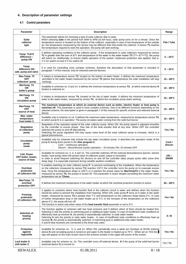
Parameter Description Range
Solar collector
type
This parameter allows for choosing a type of solar collector (flat or tube). When selecting tube in the period from 8AM to 5PM (at full hour), solar pump turns on for a minute. Since the temperature sensor is located on the bottom of the collector, especially in case of low temperature of the outside air, the temperature measured by the sensor may be different than that inside the collector. If sensor T1 reaches the temperature required to start the operation, the pump will start working.
Flat / Tube
Temp. T1&T2 difference – pump ON
It defines operating conditions of the collector pump. If the temperature in solar collectors measured by sensor T1 is greater than the sum of ΔT1 and temperature of the water in the water heater T2 (T1> ΔT1+T2), the pump will switch on. Additionally, to ensure stable operation of the system, hysteresis protection was applied, that is,
1C for switch-on and 2C for switch-off.
5 – 15C
Temp. difference ON
add. pump and valve
It is used for controlling more complex schemes, therefore the description of that parameter is included in paragraph 7 of this manual, only for selected external devices.
5 – 15C
Max.Temp. T2 OFF
collectors’ pump
It relates to temperature sensor T2, located on the bottom of water heater. It defines the maximum temperature permitted in the water heater,measured by the sensor T2 (above that temperature the solar installation will stop working).
10 – 85C
MinTemp. T3 ON
boiler’s pump
Available in schemes no. 6 and 14. It defines the minimum temperature at sensor T3, at which external device K (boiler) is switched on.
10 – 85C
MinTemp. T4 ON
circulation pump
It relates to temperature sensor T4, located on the top of water heater. It defines the minimum temperature of water in the water heater, measured by sensor T4, at which the circulation pump starts working.
10 – 85C
MaxTemp. T4 OFF
source of heat
The maximum temperature at which an external device such as boiler, electric heater or heat pump is switched off. This parameter is used in more complex schemes. Due to its different functions depending on the selected scheme, the description is given in paragraph 7 of this manual for specific scheme and selected external device.
10 – 85C
Max. water temperature from boiler C
Available only in scheme no 14. It defines the maximum water temperature, measured by temperature sensor T4, at which pump C is in operation. The pump circulates water coming from the solid-fuel burner.
10 – 85C
Regulation of collectors’
pump
Regulation of the operation speed of the solar collector pump. When ON, the pump speed is adjusted smoothly by the controller to ensure proper flow rate of the heat transfer fluid at any time. When OFF the controller switches the pump on and off alternatively. Switching the pump regulation ON may cause noise level of the solar collector pump to increase, which is a typical phenomenon.
Yes / No
Circulation pump mode
Available only for schemes that include the tap water circulation pump. It describes the operation mode of the pump C during times preset in the time program C.
- Cont – continuous operation - Discon – discontinuous (cyclic) operation – 10 minutes ON, 10 minutes OFF
Cont / Discon
Coll. Power OFF boiler, heater,
source of heat
Available for schemes no. 3, 4, 5 and 14. The controller switches off the external device/devices (burner, electric heater, heat pump) when the preset value of collectors power output is exceeded. In order to avoid frequent switching the devices on and off the controller takes proper action after some time delay (lag). It is especially important during variable weather conditions.
100 – 3000W
Overheat protection
of collectors ON
It enables switching on solar collector pump P to prevent overheating of the installation. When the temperature
on the collectors (measured by sensor T1) reaches 110C the controller turns the pump on to evacuate excess
heat. Once the temperature drops to 100C or it reaches the preset value for MaxTempT2 in the water heater, measured by sensor T2, the pumps is turned off. This parameter is active despite exceeding the maximum water temperature set as T2max.
Yes / No
MaxTemp. T2 overheat
protection OFF It defines the maximum temperature in the water heater at which the overheat protection function is active. 60 – 85C
Freezing protection
of collectors ON
It applies to countries where heat transfer fluid in the collector circuit is water and defines when the function should be active to prevent the installation from freezing. When ON, solar pump P turns on if water in the water
heater, measured by sensor T2 is greater than 7C and temperature on the collectors drops below 0C. In case
of further temperature drop in the water heater up to 4C or the increase of the temperature on the collectors
above 0C, the pump will turn off.
The function is active only when value of the heat transfer fluid parameter is set to 0C.
Yes / No
Selection of heating priority
The function applies to schemes with two heat receivers and It defines which of them should be heated first. Selecting A sets the priority to swimming pool or additional water heater. In case of insufficient solar conditions to effectively heat up receiver A, the priority is automatically switched to solar water heater. Selecting B sets the priority to solar water heater. In case of insufficient solar conditions to effectively heat up receiver B, the priority is automatically switched to swimming pool or additional solar water heater. A and B heat receivers are connected to the three-way valve.
A / B
Protection against
legionella
Available for schemes no. 3, 4, and 14. When ON, periodically once a week (on Sundays at 00:00) external
device K and circulating pump is turned on and water in the heater is heated up to 70C - When set on YES the L sign will appear on the main screen next to the scheme number in the upper left corner of the screen.
Yes / No
Lock boiler K with boiler C
Available only for scheme no. 14. The controller turns off external device K if the pump of the solid-fuel burner (external device C) is turned on.
Yes / No

HEWALEX 01.08.2011 9 / 18
5. Calculating instantaneous power and thermal energy
The controller is featured with a function of calculating instantaneous power and thermal energy produced by a solar collector installation. The function is available for all installation schemes with a single solar collector pump P and temperature sensor T3 connected on the return to the solar collectors. Also, additional parameters need to be set properly:
Heat transfer fluid – the parameter related to specific heat of the substance used as heat transfer fluid and defines its solidification
temperature. The temperature value is given on the fluid original container. Alternatively, contact the supplier of the fluid for information.
Flow rate – the parameter describing the flow rate of the heat transfer fluid in the installation. In order to configure it properly, the following parameters are to be set:
Nominal flow rate - proper value depends on the number of collectors used in the installation. In the edit mode insert the proper value and then set it on the flow meter on ZPS unit. The required flow rate is set by the modification of pump speed (gear) and by turning the regulation screw on the flow meter. The bottom of the float gives the actual flow rate.
Minimum flow rate – that function causes the solar collector pump to operate at the lowest speed (gear) and reduction of the flow rate. Read out the flow rate value from the flow meter on the ZPS unit and then insert it in the controller in the edit mode. If the float in the flow meter is not moving at the minimum flow rate, increase pump speed (gear).
Figure 9. Graphic representation of the set flow rate.
Flow rate values set by the user define the flow rate characteristics necessary for calculating solar collector power output at variable speed of solar collector pump P.
ATTENTION !!! Setting both nominal and minimum flow rate values is required when P solar collector pump is set on automatic speed regulation. When the pump automatic speed regulation is OFF, only nominal flow rate needs to be set.
6. Remaining controller options
6.1 Controller settings
This menu describes general functions of the controller such as: Date and time – enables setting current date and time, Display – enables setting display contrast and time after which the controller switches into standby mode – when at standby, pressing
any key switches the controller back to the active mode, Sound Settings – enables setting sound alerts in case of damage or disconnecting temperature sensors necessary for proper
operation of the installation and sound signals of the pressed key. Language – allows for selecting available language versions.
6.2 Cooling function – available only for installations with flat solar collectors
It allows for cooling water in a water heater by switching solar pump P in a preset time interval, which starts from 00:00 up to the hour input in Stop cooling [h] function. The option is active when the cooling function is set ON (Night cooling – YES) and temperature in the water heater, measured by sensor T2, is greater or equal to the temperature value input in Start cooling parameter. An actual cooling process will take place until water in the water heater reaches the value preset in Stop cooling parameter or the time interval elapses, as set in Stop cooling [h] function. During cooling only solar pump P is in operation. Other pumps or three-way valves are switched off.
6.3 Holiday settings – available for specific schemes only
This function enables switching off external devices connected to the controller in a given time interval, selected by the user. When activated, the main screen displays a holiday message alternatively with a current installation scheme diagram.

HEWALEX 01.08.2011 10 / 18
6.4 Default settings
This function restores default settings of the controller. It can be found in Parameters settings menu, as the last listing. Entering
that option and pressing will replace current settings with the default settings and saves it in the controller memory.
7. Installation schemes description
7.1 Tap water heating – controlling solar pump – scheme no.1
Controlling solar pump – P speed regulation disabled. Solar collector pump P will be switched on if temperature in collectors, measured by sensor T1, is greater than that measured by
sensor T2 (in the bottom of the water heater) by the value of ΔT1. It will remain turned on until the ΔT1 drops below the preset value (T1-T2> ΔT1) or water temperature in the water heater reaches the value preset for T2max. Additionally, a hysteresis protection has been used
- 1C for switch-on and 2C for switch-off. Controlling solar pump – P speed regulation enabled. solar pump P is switched on or off according to the above principles, but the controller adjusts the pump speed depending on
temperature difference (T1-T2) and the value preset for ΔT1. This enables effective energy transfer from the collectors at variable solar conditions.
ATTENTION !!! Dashed lines shown on electrical diagram denote the sensors that are not necessary for proper operation of the controller.
Figure 10. Graphic and electric representation of scheme no.1.
7.2 Tap water heating – controlling the solar pump and circulation pump – scheme no. 2
Controlling solar pump Analogical to scheme no. 1 – see 7.1
Controlling the circulation pump
The circulation pump is switched on only in periods preset in Parameters settings/Time program C. The pump can operate in two
modes, i.e. continuous or discontinuous (10 minutes ON/10 minutes OFF). The pump mode of operation is selected in Control parameters
menu. Additionally, the operation is limited by temperature sensor T4 (in the upper part of water heater). If the temperature at T4 is lower
than temperature value preset for MinTemp T4 the circulation pump is turned off.
Figure 11. Graphic and electric representation of scheme no.2.
7.3 Tap water heating – controlling the solar pump, circulation pump and external device K (boiler) – scheme no. 3
Controlling solar pump P Analogical to scheme no. 1 – see 7.1 Controlling the circulation pump

HEWALEX 01.08.2011 11 / 18
Analogical to scheme no. 2 – see 7.2 Controlling external device K to heat tap water
external device K (boiler) is switched on only in periods preset in Parameters settings/Time program K. It is switched on when
temperature, measured by sensor T4 (on the top of the water heater) is lower than that preset for T4max. The boiler will be switched off
when temperature measured by T4 sensor increases above the value T4max. Additionally, the operation of the boiler can be set to be
dependent on solar collectors instantaneous power output. In such case, the device will be switched off if the calculated instantaneous
power output of collectors is greater than that preset in Parameters settings menu. For power output calculations temperature sensor T3
must be connected.
There are two methods of controlling/switching on the boiler:
1. Connecting respective contacts inside the boiler.
2. By means of the temperature sensor input inside the boiler. Selecting appropriate resistors can simulate the desired
switch-on and switch-off temperatures of the device. An exemplary resistivity table for different brand boilers is given below.
ATTENTION !!! the original tap water temperature sensor is to be removed.
Table 2. Description of controller inputs and outputs
Figure 12. Graphic and electric representation of scheme no.3.
7.4 Tap water heating – controlling the solar pump, circulation pump and external device K (electric heater) – scheme no. 4
Controlling solar pump P Analogical to scheme no. 1 – see 7.1 Controlling the circulation pump
Analogical to scheme no. 2 – see 7.2
Controlling the electrical heater to heat tap water
Analogously as for the boiler in the scheme no. 3 – see 7.3
Manufacturer brand R1 resistor [kΩ]
Temp. 20 30°C
R2 resistor [kΩ]
Temp. 70 80°C
Beretta 9,0 14,0 1,8 2,0
Buderus 8,0 12,5 1,2 1,7
De-Dietrich 10,0 15,0 1,8 2,3
Junkers 10,0 14,8 1,9 2,4
Vaillant 3,5 3,3 0,4 0,6
Viessmann 9,0 15,0 1,5 1,8
HEWALEX 01.08.2011 12 / 18
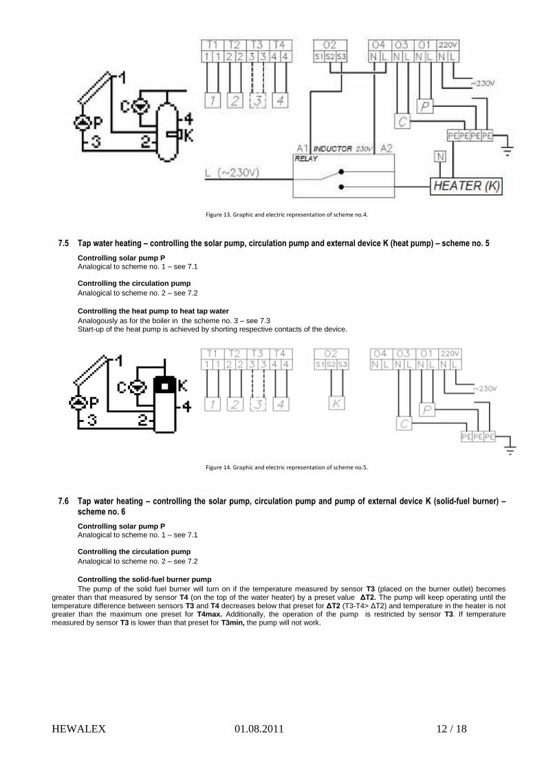
Figure 13. Graphic and electric representation of scheme no.4.
7.5 Tap water heating – controlling the solar pump, circulation pump and external device K (heat pump) – scheme no. 5
Controlling solar pump P Analogical to scheme no. 1 – see 7.1 Controlling the circulation pump
Analogical to scheme no. 2 – see 7.2
Controlling the heat pump to heat tap water
Analogously as for the boiler in the scheme no. 3 – see 7.3 Start-up of the heat pump is achieved by shorting respective contacts of the device.
Figure 14. Graphic and electric representation of scheme no.5.
7.6 Tap water heating – controlling the solar pump, circulation pump and pump of external device K (solid-fuel burner) – scheme no. 6
Controlling solar pump P Analogical to scheme no. 1 – see 7.1 Controlling the circulation pump
Analogical to scheme no. 2 – see 7.2
Controlling the solid-fuel burner pump
The pump of the solid fuel burner will turn on if the temperature measured by sensor T3 (placed on the burner outlet) becomes greater than that measured by sensor T4 (on the top of the water heater) by a preset value ΔT2. The pump will keep operating until the temperature difference between sensors T3 and T4 decreases below that preset for ΔT2 (T3-T4> ΔT2) and temperature in the heater is not greater than the maximum one preset for T4max. Additionally, the operation of the pump is restricted by sensor T3. If temperature measured by sensor T3 is lower than that preset for T3min, the pump will not work.

HEWALEX 01.08.2011 13 / 18
Figure 15. Graphic and electric representation of scheme no.6.
7.7 Two water heater system – reheating a burner water heater with surplus energy from the solar water heater by use of a mixing pump (K)
Controlling solar pump P Analogical to scheme no. 1 – see 7.1 Controlling the circulation pump
Analogical to scheme no. 2 – see 7.2 Controlling mixing pump K The mixing pump will switch on when temperature measured by sensor T2 (in a solar collector heater) becomes greater than that
measured by sensor T4 (in a burner water heater) by a preset value for ΔT2. The pump remains ON until the temperature difference between sensors T2 and T4 drops below the value of ΔT2 (T2-T4> ΔT2) and temperature inside the burner heater reaches the maximum preset value T4max.
Figure 16. Graphic and electric representation of scheme no.7.
7.8 Two water heater system – reheating a burner water heater with surplus energy from the solar water heater by use of circulation return
Controlling solar pump P Analogical to scheme no. 1 – see 7.1 Controlling the circulation pump
Analogical to scheme no. 2 – see 7.2 Controlling the three-way valve Three-way valve will direct flow to water heater B when temperature measured by sensor T2 (in a solar collector heater) becomes
greater than that measured by sensor T4 (in a burner water heater) by a preset value for ΔT2. The valve will remain is such position until the temperature difference between sensors T2 and T4 drops below the value of ΔT2 (T2-T4> ΔT2) and temperature inside the burner heater reaches the maximum preset value T4max. In opposite situation the circulation return is always directed to the burner heater A.
Figure 17. Graphic and electric representation of scheme no.8.
HEWALEX 01.08.2011 14 / 18
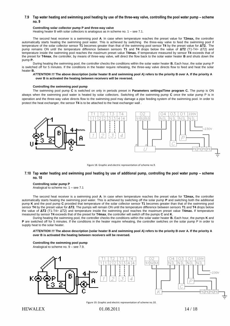
7.9 Tap water heating and swimming pool heating by use of the three-way valve, controlling the pool water pump – scheme no. 9
Controlling solar collector pump P and three-way valve Heating heater B with solar collectors is analogous as in scheme no. 1 – see 7.1. The second heat receiver is a swimming pool A. In case when temperature reaches the preset value for T2max, the controller
automatically starts heating the swimming pool water. This is achieved by switching the three-way valve to feed the swimming pool if temperature of the solar collector sensor T1 becomes greater than that of the swimming pool sensor T4 by the preset value for ΔT2. The pump remains ON until the temperature difference between sensors T1 and T4 drops below the value of ΔT2 (T1-T4> ΔT2) and temperature inside the swimming pool reaches the maximum preset value T4max. If temperature measured by sensor T4 exceeds that of the preset for T4max, the controller, by means of three-way valve, will direct the flow back to the solar water heater B and shuts down the pump P.
During heating the swimming pool, the controller checks the conditions within the solar water heater B. Each hour, the solar pump P is switched off for 5 minutes. If the conditions in the heater require reheating, the three-way valve directs flow to feed and heat the solar heater B.
ATTENTION !!! The above description (solar heater B and swimming pool A) refers to the priority B over A. If the priority A
over B is activated the heating between receivers will be reversed.
Controlling the swimming pool pump
The swimming pool pump C is switched on only in periods preset in Parameters settings/Time program C. The pump is ON
always when the swimming pool water is heated by solar collectors. Switching off the swimming pump C once the solar pump P is in
operation and the three-way valve directs flow to the swimming pool may damage a pipe feeding system of the swimming pool. In order to
protect the heat exchanger, the sensor T4 is to be attached to the heat exchanger wall .
Figure 18. Graphic and electric representation of scheme no.9.
7.10 Tap water heating and swimming pool heating by use of additional pump, controlling the pool water pump – scheme no. 10
Controlling solar pump P Analogical to scheme no. 1 – see 7.1
The second heat receiver is a swimming pool A. In case when temperature reaches the preset value for T2max, the controller automatically starts heating the swimming pool water. This is achieved by switching off the solar pump P and switching both the additional pump K and the pool pump C provided that temperature of the solar collector sensor T1 becomes greater than that of the swimming pool sensor T4 by the preset value for ΔT2. The pumps will remain ON until the temperature difference between sensors T1 and T4 drops below the value of ΔT2 (T1-T4> ΔT2) and temperature inside the swimming pool reaches the maximum preset value T4max. If temperature measured by sensor T4 exceeds that of the preset for T4max, the controller will switch off the pumps C and K.
During heating the swimming pool, the controller checks the conditions within the solar water heater B. Each hour, the pumps K and P are switched off for 5 minutes. If the conditions in the heater require reheating, the controller switches on the solar pump P in order to supply heat to the solar heater.
ATTENTION !!! The above description (solar heater B and swimming pool A) refers to the priority B over A. If the priority A
over B is activated the heating between receivers will be reversed.
Controlling the swimming pool pump
Analogical to scheme no. 9 – see 7.9.
Figure 19. Graphic and electric representation of scheme no.10.
HEWALEX 01.08.2011 15 / 18
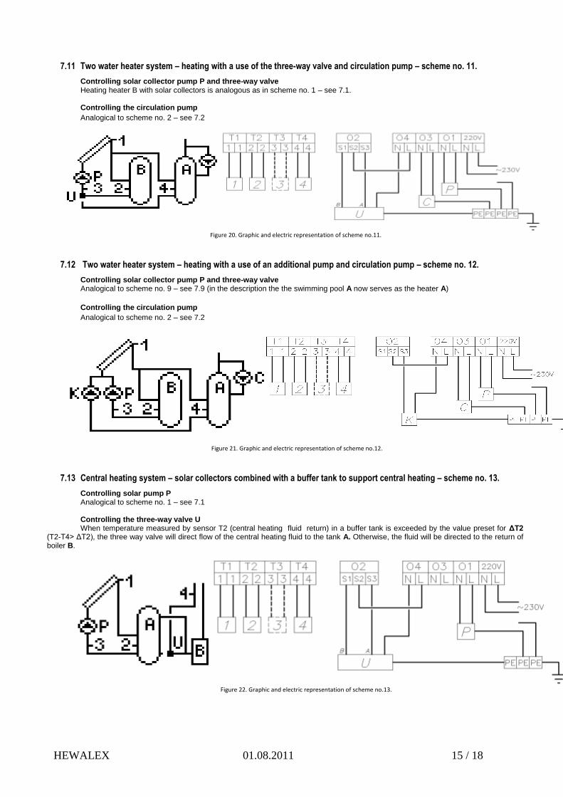
7.11 Two water heater system – heating with a use of the three-way valve and circulation pump – scheme no. 11.
Controlling solar collector pump P and three-way valve Heating heater B with solar collectors is analogous as in scheme no. 1 – see 7.1. Controlling the circulation pump
Analogical to scheme no. 2 – see 7.2
Figure 20. Graphic and electric representation of scheme no.11.
7.12 Two water heater system – heating with a use of an additional pump and circulation pump – scheme no. 12.
Controlling solar collector pump P and three-way valve Analogical to scheme no. 9 – see 7.9 (in the description the the swimming pool A now serves as the heater A)
Controlling the circulation pump
Analogical to scheme no. 2 – see 7.2
Figure 21. Graphic and electric representation of scheme no.12.
7.13 Central heating system – solar collectors combined with a buffer tank to support central heating – scheme no. 13.
Controlling solar pump P Analogical to scheme no. 1 – see 7.1 Controlling the three-way valve U When temperature measured by sensor T2 (central heating fluid return) in a buffer tank is exceeded by the value preset for ΔT2
(T2-T4> ΔT2), the three way valve will direct flow of the central heating fluid to the tank A. Otherwise, the fluid will be directed to the return of boiler B.
Figure 22. Graphic and electric representation of scheme no.13.
HEWALEX 01.08.2011 16 / 18
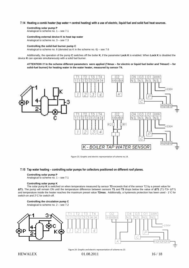
7.14 Heating a combi heater (tap water + central heating) with a use of electric, liquid fuel and solid fuel heat sources.
Controlling solar pump P Analogical to scheme no. 1 – see 7.1 Controlling external device K to heat tap water
Analogical to scheme no. 3 – see 7.3 Controlling the solid-fuel burner pump C
Analogical to scheme no. 6 (denoted as K in the scheme no. 6) – see 7.6 Additionally, the operation of the pump C switches off the boiler K, if the parameter Lock K is enabled. When Lock K is disabled the
device K can operate simultaneously with a solid fuel burner. ATTENTION !!! In the scheme different parameters were applied (T4max – for electric or liquid fuel boiler and T4maxC – for
solid-fuel burner) for heating water in the water heater, measured by sensor T4.
Figure 23. Graphic and electric representation of scheme no.14.
7.15 Tap water heating – controlling solar pumps for collectors positioned on different roof planes.
Controlling solar pump P Analogical to scheme no. 1 – see 7.1 Controlling solar pump K The solar pump K is switched on when temperature measured by sensor T3 exceeds that of the sensor T2 by a preset value for
ΔT1. The pump will remain ON until the temperature difference between sensors T1 and T3 drops below the value of ΔT1 (T1-T3> ΔT1)
and temperature inside the heater reaches the maximum preset value T2max. Additionally, a hysteresis protection has been used - 1C for
switch-on and 2C for switch-off. Controlling the circulation pump C
Analogical to scheme no. 2 – see 7.2
Figure 24. Graphic and electric representation of scheme no.15
HEWALEX 01.08.2011 17 / 18
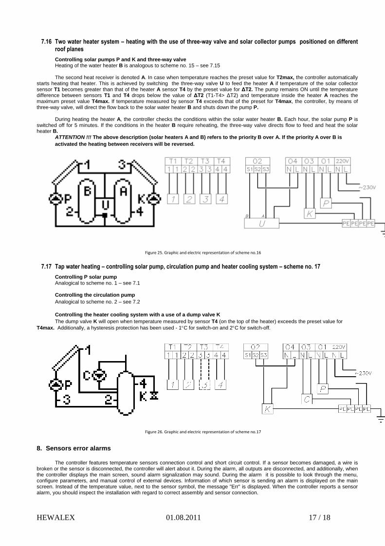
7.16 Two water heater system – heating with the use of three-way valve and solar collector pumps positioned on different roof planes
Controlling solar pumps P and K and three-way valve Heating of the water heater B is analogous to scheme no. 15 – see 7.15 The second heat receiver is denoted A. In case when temperature reaches the preset value for T2max, the controller automatically
starts heating that heater. This is achieved by switching the three-way valve U to feed the heater A if temperature of the solar collector sensor T1 becomes greater than that of the heater A sensor T4 by the preset value for ΔT2. The pump remains ON until the temperature difference between sensors T1 and T4 drops below the value of ΔT2 (T1-T4> ΔT2) and temperature inside the heater A reaches the maximum preset value T4max. If temperature measured by sensor T4 exceeds that of the preset for T4max, the controller, by means of three-way valve, will direct the flow back to the solar water heater B and shuts down the pump P.
During heating the heater A, the controller checks the conditions within the solar water heater B. Each hour, the solar pump P is
switched off for 5 minutes. If the conditions in the heater B require reheating, the three-way valve directs flow to feed and heat the solar heater B.
ATTENTION !!! The above description (solar heaters A and B) refers to the priority B over A. If the priority A over B is
activated the heating between receivers will be reversed.
Figure 25. Graphic and electric representation of scheme no.16
7.17 Tap water heating – controlling solar pump, circulation pump and heater cooling system – scheme no. 17
Controlling P solar pump Analogical to scheme no. 1 – see 7.1 Controlling the circulation pump
Analogical to scheme no. 2 – see 7.2
Controlling the heater cooling system with a use of a dump valve K
The dump valve K will open when temperature measured by sensor T4 (on the top of the heater) exceeds the preset value for
T4max. Additionally, a hysteresis protection has been used - 1C for switch-on and 2C for switch-off.
Figure 26. Graphic and electric representation of scheme no.17
8. Sensors error alarms
The controller features temperature sensors connection control and short circuit control. If a sensor becomes damaged, a wire is broken or the sensor is disconnected, the controller will alert about it. During the alarm, all outputs are disconnected, and additionally, when the controller displays the main screen, sound alarm signalization may sound. During the alarm it is possible to look through the menu, configure parameters, and manual control of external devices. Information of which sensor is sending an alarm is displayed on the main screen. Instead of the temperature value, next to the sensor symbol, the message "Err" is displayed. When the controller reports a sensor alarm, you should inspect the installation with regard to correct assembly and sensor connection.

HEWALEX 01.08.2011 18 / 18
9. Information regarding labeling and disposal of waste electric and electronic equipment
The product is designated for separate collection at an appropriate collection point. Do not dispose of as household waste. Proper disposal of waste electric and electronic equipment will help avoid potential environmental and human hazards. The responsibility of selective collection of waste electric and electronic equipment lies upon the user, who should dispose of such equipment at an appropriate collection point.


![[XLS]lbacon/acct400/templates/Chap003.xls · Web viewGiven P03-34 P03-34 Given P03-32 P03-32 Given P03-30 P03-30 Given P03-27 P03-27 Given P03-26 P03-26 Given P03-25 P03-25 Given](https://static.fdocuments.in/doc/165x107/5ae12dc87f8b9a6e5c8e6532/xls-lbaconacct400templateschap003xlsweb-viewgiven-p03-34-p03-34-given-p03-32.jpg)