Fw Murphy Level Maintainer Manual
14
00-02-0423 Revised 08-12-09 Section 15 Lube Level Maintainer Models LM2000/LM2000S Installation Instructions
-
Upload
irwindsouza -
Category
Documents
-
view
48 -
download
3
description
OIL LEVEL MAINTAINER
Transcript of Fw Murphy Level Maintainer Manual

00-02-0423Revised 08-12-09
Section 15
Lube Level MaintainerModels LM2000/LM2000S
Installation Instructions
In order to consistently bring you the highest quality, full featured products, we reserve the right to change our specifications and designs at any time. The latest version of this manual can be found at www.fwmurphy.com.
Warranty - A two year warranty on materials and workmanship is given with this FW Murphy product. A copy of the warranty may be viewed or printed by going to www.fwmurphy.com/support/warranty.htm. In the event of a fault or technical query, please contact your Murphy representative for technical support.
Please read the following information before installing.BEFORE BEGINNING INSTALLATION OF THIS MURPHY PRODUCT:
• A visual inspection of this product for damage during shipping is recommended before installation.
• It is your responsibility to ensure that qualified mechanical and electrical technicians install this product.
• Disconnect all electrical power to the machine.• Make sure machine cannot operate during installation.• Follow all safety warnings of the machine manufacturer.• Read and follow all installation instructions. • Please contact FW MURPHY immediately if you have any
questions.

Table of ContentsGeneral Information . . . . . . . . . . . . . . . . . . . . . . . . . . . . . . . . . . . . . . . . . . . . . . . . . . . . . . . . 1
Description ............................................................................................................................ 1
Dimensions ........................................................................................................................... 1
Operating Range of the Snap-Switch ................................................................................... 1
Thumb-Valve™ Operation .................................................................................................... 2
Service Parts (Specify part number) ..................................................................................... 2
Optional Hose Kit: 15000355................................................................................................ 2
Optional Vent Fittings Kit: 15000954 .................................................................................... 2
Typical Installation . . . . . . . . . . . . . . . . . . . . . . . . . . . . . . . . . . . . . . . . . . . . . . . . . . . . . . . . . 3
Mounting the LM2000 .......................................................................................................... 3
Pipe Bracket Mounting (15000238) ...................................................................................... 3
Mounting with Universal Bracket (15000370) ....................................................................... 3
Connecting Fittings and Hoses............................................................................................. 4
Connecting the LM2000 to an Oil Supply Tank .................................................................... 5
Switch Test ........................................................................................................................... 5
LM2000 Typical Installation Shown with FSV Series Valves ................................................ 6
Specifications . . . . . . . . . . . . . . . . . . . . . . . . . . . . . . . . . . . . . . . . . . . . . . . . . . . . . . . . . . . . . 7

(THIS PAGE INTENTIONALLY LEFT BLANK)

General InformationDescriptionThe Murphy LM2000 model maintains the crankcase oil level of an engine, pump or compressor. Adjusted to the correct running-oil-level, the LM2000 will replenish oil as it is used. An integral, low-level switch will alarm and/or shutdown the equipment if supply oil is lost and the equipment continues to use oil.
Dimensions
Operating Range of the Snap-SwitchFigure 1 shows the LM2000 dial and the operating range of the switch. If level is within the designated zones the switch will activate.The switch activates approximately 1/4 in. (6 mm) from the bottom of the low zone. The dial in Figure 1 shows that if level continues to drop into the low-low zone, a shutdown will occur.
Figure 1
NOTE: Color zones on dial face show approximate normal operating zones. Actual conditions may vary depending upon operating characteristics of the engine. Placement of the LM2000 according to the above instructions will compensate for these conditions.
Section 15 00-02-042308-12-09 - 1 -
General Information—continued
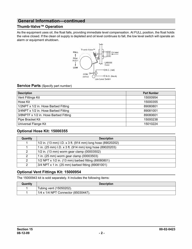
Thumb-Valve™ OperationAs the equipment uses oil, the float falls, providing immediate level compensation. At FULL position, the float holds the valve closed. If the clean oil supply is depleted and oil level continues to fall, the low level switch will operate an alarm or equipment shutdown.Service Parts (Specify part number)
Optional Hose Kit: 15000355
Optional Vent Fittings Kit: 15000954The 15000943 kit is sold separately. It includes the following items:
Description Part NumberVent Fittings Kit 15000954Hose Kit 150003551/2NPT x 1/2 in. Hose Barbed Fitting 890808013/4NPT x 1/2 in. Hose Barbed Fitting 890810013/8NPTF x 1/2 in. Hose Barbed Fitting 89080601Pipe Bracket Kit 15000238Universal Flange Kit 15010224
Quantity Description1 1/2 in. (13 mm) I.D. x 3 ft. (914 mm) long hose (89020202)1 1 in. (25 mm) I.D. x 3 ft. (914 mm) long hose (89020203)2 1/2 in. (13 mm) worm gear clamp (00003502)2 1 in. (25 mm) worm gear clamp (00003503)2 1/2 NPT x 1/2 in. (13 mm) barbed fitting (89080801)2 3/4 NPT x 1 in. (25 mm) barbed fitting (89081001)
Quantity Description1 Tubing vent (15050202).1 1/4 x 1/4 NPT Connector (85030447).
Section 15 00-02-042308-12-09 - 2 -
Typical InstallationMounting the LM2000
The following instructions are based on the usage of the pipe and universal mounting brackets shown on page 1.
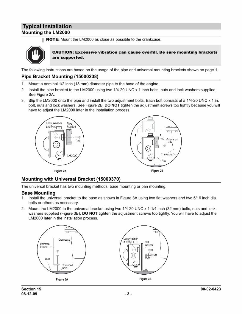
Pipe Bracket Mounting (15000238)1. Mount a nominal 1/2 inch (13 mm) diameter pipe to the base of the engine.2. Install the pipe bracket to the LM2000 using two 1/4-20 UNC x 1 inch bolts, nuts and lock washers supplied.
See Figure 2A.3. Slip the LM2000 onto the pipe and install the two adjustment bolts. Each bolt consists of a 1/4-20 UNC x 1 in.
bolt, nuts and lock washers. See Figure 2B. DO NOT tighten the adjustment screws too tightly because you will have to adjust the LM2000 later in the installation process.
Mounting with Universal Bracket (15000370)The universal bracket has two mounting methods: base mounting or pan mounting.
Base Mounting1. Install the universal bracket to the base as shown in Figure 3A using two flat washers and two 5/16 inch dia.
bolts or others as necessary.2. Mount the LM2000 to the universal bracket using two 1/4-20 UNC x 1-1/4 inch (32 mm) bolts, nuts and lock
washers supplied (Figure 3B). DO NOT tighten the adjustment screws too tightly. You will have to adjust the LM2000 later in the installation process.
NOTE: Mount the LM2000 as close as possible to the crankcase.
CAUTION: Excessive vibration can cause overfill. Be sure mounting brackets are supported.
Figure 2A Figure 2B
Figure 3A Figure 3B
Section 15 00-02-042308-12-09 - 3 -

Typical Installation—continuedMounting with Universal Bracket (15000370)—continued
Crankcase (Oil Pan) Mounting1. Install the universal bracket to the crankcase using the existing crankcase bolts (Figure 4A). Crankcase boltdiameter must be no larger than 7/16 inch (11 mm).
2. Mount the LM2000 to the universal bracket using two 1/4-20 UNC x 1- 1/4 inch bolts, nuts and lock washers supplied. DO NOT tighten the adjustment bolts too tight. You will have to adjust the LM2000 later in the instal-lation process.
3. If space between the crankcase and mounting bracket is narrow, install the universal mounting bracket to the LM2000 before installing to the crankcase oil pan.
Connecting Fittings and HosesThe following instructions are based on the Murphy optional hose kit described on page 1. If you did not order the optional hose kit, use the list designation as a guide to the required materials.1. Install the LM2000 fittings in their proper locations.
2. Attach the 1 inch (25 mm) diameter, flexible monitoring hose to the crankcase and the monitoring port on the LM2000. See Figure 5.
3. Install the 1/2 inch (13 mm) I.D. x 3 ft. (914 mm) hose to the vent connection on the LM2000 and to the vent connection on the crankcase. See Figure 5. The vent connection on the crankcase must be well above the regulated oil level. All hoses must be clear of obstructions, valleys, or dips that could create liquid traps, or gas/air pockets. The vent and crankcase connections should be as straight as possible.
NOTE: Check clearance between crankcase and mounting bracket before installing the mounting bracket. If space between the crankcase and mounting bracket does not allow installation and access to the adjustment bolts advance to Step 3.
NOTE: Apply a sealant such as Teflon®, to all threaded connections.
CAUTION: The hose must slope slightly downward from the LM2000 and MUST NOT have any droops or low spots.
NOTE: If the drain plug on the crankcase is used for the connection, we recommend instal-lation of a tee to allow draining of the crank-case for service.
Figure 4A Figure 4B
Figure 5
Section 15 00-02-042308-12-09 - 4 -

Typical Installation—continuedConnecting Fittings and Hoses—continued
BEFORE CONTINUING, VERIFY THAT ALL HOSE CLAMPS ARE TIGHT.4. Fill the crankcase to the proper oil level. With the engine running and warm, loosen the mounting bracketadjustment bolts and adjust the LM2000 so that the oil level in the sight gauge is aligned with the white “index line” on the dial (Figure 5). Tighten the adjustment bolts securely.
Connecting the LM2000 to an Oil Supply Tank1. Remove the plug from the oil inlet connection. Be sure the removable
screen, inside the connection, is clear of debris. Install the oil inlet con-nection.
2. Connect a 1/2 inch I.D. (13 mm) or larger hose to the oil inlet fitting on the LM2000 and to the shutoff valve on the oil supply tank. See Figure 5. Recommended minimum height above the LM2000 is 2 ft. (0.6m); maximum 25 ft. (7.7m). The hose must maintain a downward slope and not have low spots or droops. Maximum head pressure rating is 9.50 psi or 25 ft oil (head pressure).
3. Before filling the supply tank with oil, be sure the tank is clean and dry and the shutoff valve is closed. Also, be sure all hoses and clamps are tight. Fill the tank with CLEAN oil.
4. After oil supply tank is full, open the shutoff valve. Next, make the proper electrical connections for the application. (See Snap-switch ratings and schematic on page 1.)
Switch TestTo test the shutdown or alarm functions perform the following:
1. Unscrew the vent fittings.2. Using a long narrow shank screw driver, gently insert until contact is felt with float arm. Gently push the float
arm down.3. Verify proper switch operation
WARNING: Overfill condition can be caused by excessive inlet pressure and/or improper “vent to crankcase” installation.
NOTE: Installations with closed vent systems can only be tested with the engine off.
Figure 6
Section 15 00-02-042308-12-09 - 5 -
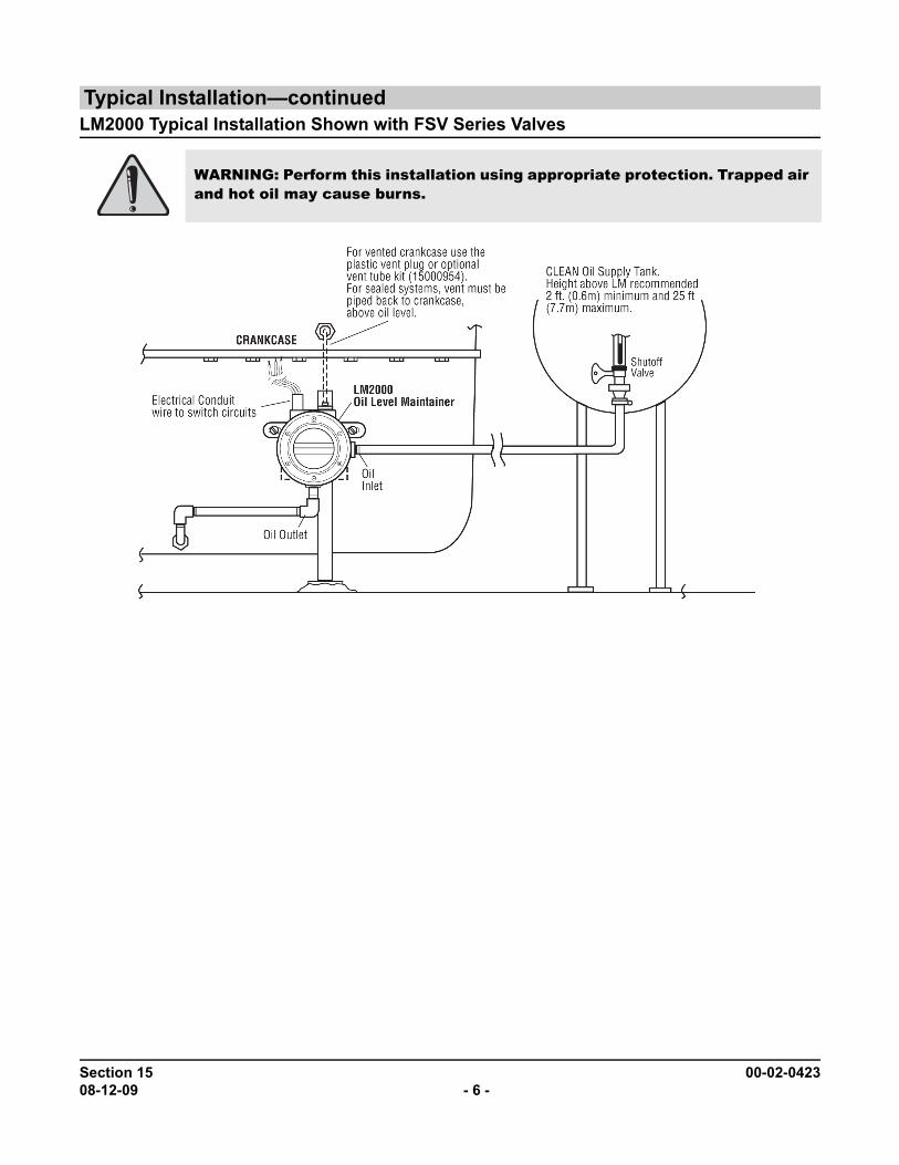
Typical Installation—continued
LM2000 Typical Installation Shown with FSV Series ValvesWARNING: Perform this installation using appropriate protection. Trapped air and hot oil may cause burns.
Section 15 00-02-042308-12-09 - 6 -

SpecificationsCrankcase Balance Vent Connection: 1/2 NPTF (top).Inlet Connection: 1/2 NPTF with removable screen (side).Outlet Connection: LM2000 3/4 NPTF (bottom).
LM2000S 2 x 3/8 NPTF (side)1 x 3/4 NPTF (bottom)
Thumb-Valve™ Material: Viton.Snap-switch: SPDT rating 10 A, 125 VAC; 0.5 A, 125 VDC; 10 A, 30 VDC.Wire leads: 18 AWG x 14 in. ± 2 in. (355 mm) length.Conduit Connection: 1/2 inch conduit (female, top).Case: Die cast aluminumLens: Clear “Frog Eye” non-staining, high impact, high temperature nylon; UV and heat stabilized.Dial: High visibility white background with green and white “index” lines for normal level indication.Maximum Inlet Pressure: 9.50 psi/25 ft. oil (head pressure).Maximum Case Pressure: 15 psi (103 kPa).Maximum Differential: 2 in. (51 mm) between running and stopped.Maximum Ambient Temperature: 250°F (121°C).Float: BrassFlow Rates: SAE 40 motor oil @ 32°F (0°C) with 2 ft. head pressure: 0.5 GPH (1.9 LPH).
NOTE: Friction losses due to piping not considered.
Section 15 00-02-042308-12-09 - 7 -

(THIS PAGE INTENTIONALLY LEFT BLANK)
MURPHY, and the Murphy logo are registered and/or common law trademarks of Murphy Industries, Inc. This document, including textural matter and illustrations, is copyright protected by Murphy Industries, Inc., with all rights reserved. (c) 2007 Murphy Industries, Inc. Other third party product or trade names referenced herein are the property of their respective owners and are used for identification purposes only.
Section 15 00-02-042308-12-09 - 9 -