Fuzzy Vehicle Dynamic Control for a Three-Wheeled Vehicle ... · PDF fileFuzzy Vehicle Dynamic...
13
International Journal of Automotive Engineering Vol. 4, Number 4, Dec 2014 Fuzzy Vehicle Dynamic Control for a Three-Wheeled Vehicle Using Tilt Mechanism S. A. Milani 1 , S. Azadi 2 1M.Sc. Student, Dep. of Mechanical Engineering, Middle East Technical University, Ankara, Turkey (Formerly K. N. Toosi University of Technology, Tehran, Iran) 2Asst. Professor, Dep. of Mechanical Engineering, K. N. Toosi University of Technology, Tehran, Iran Abstract Nowadays, the use of small vehicles is spreading among urban areas and one sort of these vehicles are three-wheeled vehicles (TWVs) which can be competitive with four-wheeled urban vehicles (FWVs) in aspects such as smallness, simple manufacturing, and low tire rolling resistance, fuel consumption and so on. The most critical instability associated with TWVs is the roll over. In this paper a tilt control mechanism has been modeled which can reduce the danger of roll over by leaning the vehicle towards the turning center in order to decrease the amount of lateral load transfer (LLT), and by doing so, system combines the dynamical abilities of a passenger car with a motorcycle. A 3 degree of freedom vehicle model is simulated at constant speed in MATLAB-Simulink environment and a fuzzy algorithm is developed to control such a non-linear system with appropriate tilting torque. Results are interpreted in presence and absence of controller with different longitudinal speeds and steering inputs; the results are also compared to behavior of a similar FWV and this is concluded that the tilt control system could countervail deficiencies of the TWV compared to the FWV. Keywords: Three-Wheeled Vehicle, Tilt Mechanism, Roll Over, Fuzzy Control, Vehicle Dynamics, Simulation 1. Introduction Today, small vehicles play a significant role in our daily life which causes the small city cars to be very popular among people especially in crowded regions. Low fuel consumption, low emission, small dimensions and affordable prices are some reasons for such popularity [1]. TWVs are also placed in this category and are considered as small urban vehicles which are also used in countries such as China and India as transporter vehicles and sometimes for cargo transfer reasons. A noticeable advantage of these vehicles in comparison to FWVs is their ability to combine powertrain and suspension mechanisms used in motorcycles and passenger cars in order to minimize the complexity of systems; for instance, if the power is to be transferred to the single wheel, the mechanism will be easily designed without any need to differentials; or if the single wheel is located at the front, the steering mechanism could be a direct steering mechanism or any system much simpler than the conventional FWV. Generally, these kinds of modifications could also cause in total weight reduction and subsequently better fuel economy. Instabilities associated with TWVs can be categorized into two types: lateral issues arising from the loss of lateral force generation ability by the single wheeled axle; and more importantly, the deficiency of the TWVs in withstanding the LLT generated in turns and their high tendency to roll over in turns and decreasing the roll over threshold. This arises from the fact that all LLT generated in the turn should be compensated by the normal tire loads in the two-wheeled axle [2]. A special control system used to counteract the roll over threat of TWVs is the Tilt Control (TC) mechanism. There are two types of TC: 1) Direct Tilt Control (DTC), 2) Steering Tilt Control (STC) [3]. DTC: In this system, actuators are located between the sprung and un sprung masses (or integrated with suspension such as the Mercedes F300). A lateral acceleration sensor is used to obtain
Transcript of Fuzzy Vehicle Dynamic Control for a Three-Wheeled Vehicle ... · PDF fileFuzzy Vehicle Dynamic...

International Journal of Automotive Engineering Vol. 4, Number 4, Dec 2014
Fuzzy Vehicle Dynamic Control for a Three-Wheeled Vehicle
Using Tilt Mechanism
S. A. Milani1, S. Azadi
2
1M.Sc. Student, Dep. of Mechanical Engineering, Middle East Technical University, Ankara, Turkey (Formerly K. N.
Toosi University of Technology, Tehran, Iran) 2Asst. Professor, Dep. of Mechanical Engineering, K. N. Toosi
University of Technology, Tehran, Iran
Abstract
Nowadays, the use of small vehicles is spreading among urban areas and one sort of these vehicles are
three-wheeled vehicles (TWVs) which can be competitive with four-wheeled urban vehicles (FWVs) in
aspects such as smallness, simple manufacturing, and low tire rolling resistance, fuel consumption and so
on. The most critical instability associated with TWVs is the roll over. In this paper a tilt control
mechanism has been modeled which can reduce the danger of roll over by leaning the vehicle towards the
turning center in order to decrease the amount of lateral load transfer (LLT), and by doing so, system
combines the dynamical abilities of a passenger car with a motorcycle. A 3 degree of freedom vehicle
model is simulated at constant speed in MATLAB-Simulink environment and a fuzzy algorithm is
developed to control such a non-linear system with appropriate tilting torque. Results are interpreted in
presence and absence of controller with different longitudinal speeds and steering inputs; the results are
also compared to behavior of a similar FWV and this is concluded that the tilt control system could
countervail deficiencies of the TWV compared to the FWV.
Keywords: Three-Wheeled Vehicle, Tilt Mechanism, Roll Over, Fuzzy Control, Vehicle Dynamics, Simulation
1. Introduction
Today, small vehicles play a significant role in our
daily life which causes the small city cars to be very
popular among people especially in crowded regions.
Low fuel consumption, low emission, small
dimensions and affordable prices are some reasons for
such popularity [1]. TWVs are also placed in this
category and are considered as small urban vehicles
which are also used in countries such as China and
India as transporter vehicles and sometimes for cargo
transfer reasons. A noticeable advantage of these
vehicles in comparison to FWVs is their ability to
combine powertrain and suspension mechanisms used
in motorcycles and passenger cars in order to
minimize the complexity of systems; for instance, if
the power is to be transferred to the single wheel, the
mechanism will be easily designed without any need
to differentials; or if the single wheel is located at the
front, the steering mechanism could be a direct
steering mechanism or any system much simpler than
the conventional FWV. Generally, these kinds of
modifications could also cause in total weight
reduction and subsequently better fuel economy.
Instabilities associated with TWVs can be
categorized into two types: lateral issues arising from
the loss of lateral force generation ability by the
single wheeled axle; and more importantly, the
deficiency of the TWVs in withstanding the LLT
generated in turns and their high tendency to roll over
in turns and decreasing the roll over threshold. This
arises from the fact that all LLT generated in the turn
should be compensated by the normal tire loads in the
two-wheeled axle [2].
A special control system used to counteract the
roll over threat of TWVs is the Tilt Control (TC)
mechanism. There are two types of TC: 1) Direct Tilt
Control (DTC), 2) Steering Tilt Control (STC) [3].
DTC: In this system, actuators are located
between the sprung and un sprung masses (or
integrated with suspension such as the Mercedes
F300). A lateral acceleration sensor is used to obtain

S. A. Milani, S. Azadi 870
International Journal of Automotive Engineering Vol. 4, Number 4, Dec 2014
the current status of the vehicle and the control
system determines the required torque to locate the
vehicle in proper tilting position at the moment. The
main disadvantage of such systems is the probable
time delay and complicated control algorithm. On the
other hand, establishing such a system will not require
the driver to possess special skills and information
about the system functioning [3].
Piyabongkam et al. conducted a research in which
a prototype is made and two control approaches are
conducted for the case (RHC Controller and a
nonlinear controller using feedback linearization) [4].
Nestor Roqueiro qt al. developed a sliding mode
direct tilt control for a TWV and results are analyzed
[5].
STC: This method is actually the same method
that a bike rider uses unconsciously when tilting the
bike in maneuvers. Generally speaking, this method is
dependent almost to the speed, steering angle and the
driver experience. The main advantage of this system
is the fast response.
In a research by Pohl and Conrads a fully
mechanical single passenger prototype is made in
Which the driver tilts the vehicle by pushing two
reciprocal pedals which is relying totally on the
physical ability and experience of the driver [6].
TC not only compensates the effect of LLT, but
also increases the lateral tire forces by generating
favorable camber angle in the tires of the vehicle.
In the following sections, a DTC is designed and
the simulation is done using MATLAB-Simulink on a
simplified TWV model with a single wheel in the
front axle.
2. 2. Vehicle Model
3. 2.1. Assumptions
Constant Longitudinal Speed: Vehicle speed is
considered constant in order to eliminate the
longitudinal motion equation. This assumption is
reasonable in most of the maneuvers.
Even Road Surface: The road is considered flat
and no imperfection is considered in the analysis.
This assumption enables us to focus on the tilting
required torque directly.
Single Wheel Location: According to the
results of previous work [1] it is concluded that in
order to have more understeering behavior which is
considered safe and stable compared to over steering,
the best location for the single wheel is at the front
end of the vehicle.
Ignored Wheel Travel: In calculation of the tire
normal loads, it is assumed that the wheel has no
significant mass and the tire normal forces are
instantly transferred to the suspension and the sprung
mass; but since we are looking for a comparison
between TWVs and FWVs in presence and absence
of TC, this assumption will not impair the
simulations.
Roll Center Height: As the design of suspension
and tilting mechanism is beyond the scope of this
investigation, the roll center height is assumed to be
zero making the tilt axis coincident with the vehicle
longitudinal axis.
Vehicle parameters are given in Appendix.
2.2. Equations of Motion [1]
SAE coordinate convention is used for obtaining
the equations of motion [7].
Lateral Motion: 𝑭𝒚,t𝒐𝒕𝒂𝒍=𝑭𝒚,𝒇+𝑭𝒚,𝒓𝒍+𝑭𝒚,𝒓𝒓=𝑴𝒕( 𝒚+ 𝒙. )=𝑴𝒕𝒂𝒚 (𝟏) Roll Motion (Uncontrolled Vehicle): Σ𝑴𝒙= (𝑭𝒛, 𝒓𝒓−𝑭𝒛,
𝒓𝒍).𝑻𝒓𝟐−𝑭𝒚,𝒂𝒍(𝒉𝑪𝑮−𝒉𝑪𝑹)=𝑰𝒔,𝒙𝒙. (𝟐) Tilt Motion (Controlled Vehicle): 𝑴+(𝒉𝑪𝑮−𝒉𝑪𝑹).𝐬𝐢𝐧 −𝑭𝒚,𝒕𝒐𝒕𝒂𝒍(𝒉𝑪𝑮−𝒉𝑪𝑹).𝐜𝐨𝐬 =𝑰𝒔,𝒙𝒙. (𝟑)
Fig1. Vehicle Coordinate System

871 Fuzzy Vehicle Dynamic Control…..
International Journal of Automotive Engineering Vol. 4, Number 4, Dec 2014
Fig2. Vehicle Tilt Model
Fig3. Mercedes F300 Tilting
Yaw Motion:
Σ𝑴𝒛=(𝑭𝒚,𝒇).𝑳𝒇−(𝑭𝒚,𝒓𝒓+𝑭𝒚,𝒓𝒍).𝑳𝒓+𝑴𝒛,𝒕𝒐𝒕𝒂𝒍=𝑰𝒛𝒛. (𝟒)
𝑴𝒛,𝒕𝒐𝒕𝒂𝒍=𝑴𝒛,𝒇+𝑴𝒛,𝒓𝒍+𝑴𝒛,𝒓𝒓 (𝟓)
Tire model used in this research is the Magic
Formula tire model [8]. Since we are dealing with
fuzzy control, there will be no limitations for linear
equations throughout the vehicle model, so it has been
chosen to use Magic Formula in order to get more
realistic results compared to other possible tire
models. The details of the tire cornering and moment
characteristics can be found in [8] and [2].
Equations of motion for the FWV are much
similar to those of TWV and are omitted for the sake
of space saving.
3. Tilt Mechanism and Control
3.1. Mechanism
Tilting mechanism used for simulation in this
paper is adopted from Mercedes-Benz F300 which
utilizes a double-wishbone suspension system
manipulated by hydraulic actuators to imply the
tilting moment between the sprung and un sprung
masses [6]. The only difference is that the effect of
springs is not considered in this analysis because of
simplicity and the type of analysis performed; in other
words, the tilting moment is directly applied between
the wheels (suspension arms) and the body.
This special double wishbone configuration is a
little different from conventional samples; the upper
arm is longer than the lower one due to the technical
fact that for better maneuverability and lateral force
we need negative camber for the outer wheel and
positive camber for the inner wheel in turns, while the
vehicle body is leaning towards inside of the turn
despite normal cars which tend to roll to the outside
of the turn. Thus the suspension geometry and the
kinematics are different in this manner. Since the
design of suspension system is not in the scope of this
paper, we use the results obtained by visual inspection
as the kinematic analysis of suspension geometry to
determine the camber angles associated with a certain
tilting angle as follows:
−
−
According to the vehicle dynamics equations
mentioned before, one can see that the whole system
is extremely nonlinear which strongly implies the use
of a nonlinear controller to take charge. Among

S. A. Milani, S. Azadi 872
International Journal of Automotive Engineering Vol. 4, Number 4, Dec 2014
nonlinear control systems, the fuzzy control is a
convenient approach if the designer has good
understanding of the system’s behavior. In this paper,
this type of controller is used to get the desired tilt
angle by applying the proper torque.
3.2. Control Approach
In the first stage, a Mamdani controller was
designed but the results were not satisfactory at all
because according to the complexity of the system it
is not easily possible to define constant membership
functions for the tilting torque such as “High”,
“Low”, etc. Thus a TSK controller is designed using
special and while very simple mathematical
expressions ( �̃� and 𝑴 𝒐𝒓 𝒂𝒍 ) which are described
later.
3.3 Desired Tilt Angle
At first, we need to define a desired tilt angle for
the vehicle in turns. This is done by thinking like the
case of a motorcycle in turn; we equal the LLT to
zero to ensure having the maximum roll stability
(
)
3.4. Controller Design
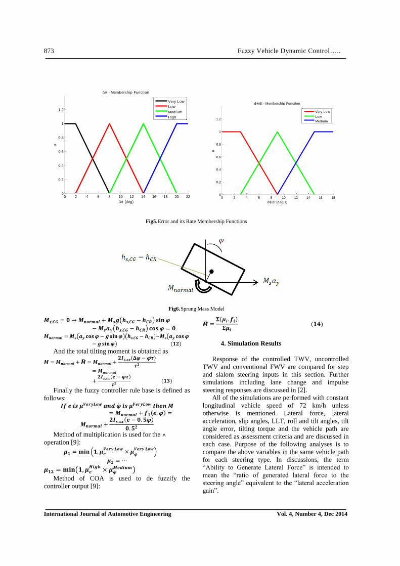
Tilt angle error and its rate of change are
considered as controller inputs which need to be
fuzzified. Maximum tilt angle is considered 45
degrees and the following membership functions are
developed to fuzzify the controller inputs,
Now we define a new variable called �̃� and it is
defined as follows:
Assuming a constant angular acceleration for the
vehicle body in tilting, applying this net amount of
torque to the body will cancel the error out in time .
This concept is used to initiate a method of
finding an appropriate expression for tilting torque
with respect to error and its rate. Then the procedure
is continued using trial and error method to find the
best suited amount of tilting torque in different
conditions with keeping an eye on the maximum
amount of torque allowed without violating the roll
stability threshold which is about 4000 N.m of tilting
torque.
We need an additional variable to find the total
acting torque with this approach; we define a variable
𝑴 𝒐𝒓 𝒂𝒍 which interprets the amount of torque
required to maintain the vehicle body in the current
leaning angle. Since the controller is responsible for
all of the interactions between the suspension and the
body (sprung and unsprung masses), this amount of
torque is needed in addition to �̃� to be implied to
make the net inserted torque be equal to �̃�. In other
words, 𝑴 𝒐𝒓 𝒂𝒍 is only compensating the effect of
LLT which will be eliminated in the desired tilt angle.
Assuming 𝒉𝒔 𝑪𝑮 𝒉𝑪𝑮 ,
Fig4. Desired Tilt Angle Model
Σ
Σ
Σ
− (
− )
(
)
𝟏
𝟐 𝟐
𝟐 −
𝟐
�̃� 𝑰𝒔 𝒙𝒙 𝟐𝑰𝒔 𝒙𝒙 −
𝟐
873 Fuzzy Vehicle Dynamic Control…..
International Journal of Automotive Engineering Vol. 4, Number 4, Dec 2014
Fig5. Error and its Rate Membership Functions
Fig6. Sprung Mass Model
𝑴𝒔 𝑪𝑮 𝑴 𝒐𝒓 𝒂𝒍 𝑴𝒔 (𝒉𝒔 𝑪𝑮 − 𝒉𝑪𝑹) 𝐬𝐢𝐧
− 𝑴𝒔𝒂𝒚(𝒉𝒔 𝑪𝑮 − 𝒉𝑪𝑹) 𝐜𝐨𝐬
𝑴 𝒐𝒓 𝒂𝒍 𝑴𝒔(𝒂𝒚 𝐜𝐨𝐬 − 𝐬𝐢𝐧 )(𝒉𝒔 𝑪𝑮 − 𝒉𝑪𝑹) 𝑴𝒔(𝒂𝒚 𝐜𝐨𝐬
− 𝐬𝐢𝐧 ) 𝟏𝟐
And the total tilting moment is obtained as
𝑴 𝑴 𝒐𝒓 𝒂𝒍 �̃� 𝑴 𝒐𝒓 𝒂𝒍 𝟐𝑰𝒔 𝒙𝒙 −
𝟐
𝑴 𝒐𝒓 𝒂𝒍
𝟐𝑰𝒔 𝒙𝒙 −
𝟐 𝟏𝟑
Finally the fuzzy controller rule base is defined as
follows: 𝑰𝒇 𝒔 𝒓𝒚𝑳𝒐 𝒂 𝒔 𝒓𝒚𝑳𝒐 𝒕𝒉 𝑴
𝑴 𝒐𝒓 𝒂𝒍 𝒇𝟏
𝑴 𝒐𝒓 𝒂𝒍 𝟐𝑰𝒔 𝒙𝒙 − 𝟓
𝟓𝟐
Method of multiplication is used for the ˄
operation [9]:
𝟏 𝐢𝐧 (𝟏 𝒓𝒚 𝑳𝒐
𝒓𝒚 𝑳𝒐
)
𝟐
𝟏𝟐 𝐢𝐧(𝟏 𝑯 𝒉
𝑴 𝒖 )
Method of COA is used to de fuzzify the
controller output [9]:
4. Simulation Results
Response of the controlled TWV, uncontrolled
TWV and conventional FWV are compared for step
and slalom steering inputs in this section. Further
simulations including lane change and impulse
steering responses are discussed in [2].
All of the simulations are performed with constant
longitudinal vehicle speed of 72 km/h unless
otherwise is mentioned. Lateral force, lateral
acceleration, slip angles, LLT, roll and tilt angles, tilt
angle error, tilting torque and the vehicle path are
considered as assessment criteria and are discussed in
each case. Purpose of the following analyses is to
compare the above variables in the same vehicle path
for each steering type. In discussions, the term
“Ability to Generate Lateral Force” is intended to
mean the “ratio of generated lateral force to the
steering angle” equivalent to the “lateral acceleration
gain”.
0 2 4 6 8 10 12 14 16 180
0.2
0.4
0.6
0.8
1
1.2
d/dt - Membership Function
d/dt (deg/s)
Very Low
Low
Medium
0 2 4 6 8 10 12 14 16 18 20 220
0.2
0.4
0.6
0.8
1
1.2
- Membership Function
(deg)
Very Low
Low
Medium
High
�̃� 𝒇
𝟏𝟒

S. A. Milani, S. Azadi 874
International Journal of Automotive Engineering Vol. 4, Number 4, Dec 2014
Table 1- Fuzzy Rule Base
Rule # Condition in moment equation
(�̃� 𝒇 )
1* 𝒔 𝒓𝒚 𝑳𝒐 𝒔 𝒓𝒚 𝑳𝒐 𝟓
2 𝒔 𝒓𝒚 𝑳𝒐 𝒔 𝑳𝒐 𝟑
3 𝒔 𝒓𝒚 𝑳𝒐 𝒔 𝑴 𝒖 𝟏𝟔
4 𝒔 𝑳𝒐 𝒔 𝒓𝒚 𝑳𝒐 𝟏
5 𝒔 𝑳𝒐 𝒔 𝒓𝒚 𝑳𝒐
6 𝒔 𝑳𝒐 𝒔 𝑴 𝒖 𝟏
7 𝒔 𝑴 𝒖 𝒔 𝒓𝒚 𝑳𝒐 𝟏 𝟓
8 𝒔 𝑴 𝒖 𝒔 𝑳𝒐 𝟏
9 𝒔 𝑴 𝒖 𝒔 𝑴 𝒖 𝟐𝟑
10 𝒔 𝑯 𝒉 𝒔 𝒓𝒚 𝑳𝒐 𝟐 𝟓
11 𝒔 𝑯 𝒉 𝒔 𝑳𝒐 𝟏 𝟔
12 𝒔 𝑯 𝒉 𝒔 𝑴 𝒖 𝟏 𝟐
Fig7. Steering Angle and Vehicle Path
4.1. Step Steering
By this analysis, we want to simulate the situation
in which the driver intends to pass a simple turn with
a constant speed and steering angle as shown in the
following figure:
Uncontrolled TWV show a lot more under
steering than the FWV which is also predictable from
the basic physics of the TWVs with a single front
wheel. The controlled TWV shows even more under
steering with respect to the uncontrolled one.
The FWV needs less slip angle to produce the
required lateral force and its ability to generate lateral
force is higher than the TWVs as expected. This
means that the FWV is still able to generate more
lateral force in higher slip angles despite the TWVs.
The controlled TWV is dealing with lower slip
angles in all tires than the uncontrolled one which
implies the role of camber angles in lateral force
production. Hence, it can be concluded that the
controlled TWV possesses more ability to generate
lateral force than the uncontrolled one due to the
contributing camber angles.
According to the same vehicle path and speed, we
may expect similar lateral acceleration for three
vehicles, but the behavior is not exactly the same and
the controlled TWV seems to produce more lateral
acceleration in a shorter time than two other vehicles.
Faster changes in normal tire forces in controlled
0 1 2 3 4 5 60
0.5
1
1.5
2
2.5
3
3.5
4
t (sec)
(
deg
)
4W
3W
3WC
0 20 40 60 80 100 120-30
-25
-20
-15
-10
-5
0
5
X(m)
Y(m
)
4W
3W
3WC

875 Fuzzy Vehicle Dynamic Control…..
International Journal of Automotive Engineering Vol. 4, Number 4, Dec 2014
TWV – and consequently faster settlement in those conditions - can be the cause of this phenomenon.
Fig8. Front Tire Slip Angles
Fig9. Rear Tire Slip Angles
Fig10. Lateral Acceleration (left)
Fig11. Lateral Load Transfer (right)
Our important purpose in using tilt control was to
minimize the LLT. In the above figure it is shown that
the controlled TWV experienced a very low amount
of LLT in steady state compared to the two normal
vehicles. The important note is that the tilting torque
causes a bit higher amount of LLT at first, but
0 1 2 3 4 5 6-5
-4.5
-4
-3.5
-3
-2.5
-2
-1.5
-1
-0.5
0
t (sec)
(
deg
)
4W-Front/Left
3W-Front
3WC-Front
0 1 2 3 4 5 6-3
-2.5
-2
-1.5
-1
-0.5
0
0.5
t (sec)
(
deg
)
4W-Rear/Left
3W-Rear/Left
3WC-Rear/Left
0 1 2 3 4 5 6-3
-2.5
-2
-1.5
-1
-0.5
0
0.5
t (sec)
(
deg
)
4W-Rear/Right
3W-Rear/Right
3WC-Rear/Righ
0 1 2 3 4 5 6-0.05
0
0.05
0.1
0.15
0.2
0.25
0.3
0.35
t (sec)
ay (
g)
4W
3W
3WC
0 1 2 3 4 5 6-5000
-4000
-3000
-2000
-1000
0
1000
t (sec)
F
z (
N)
4W
3W
3WC

S. A. Milani, S. Azadi 876
International Journal of Automotive Engineering Vol. 4, Number 4, Dec 2014
gradually this LLT is reduced dramatically with
respect to normal behavior which shows a good
success in control strategy although the steady state
error keeps the LLT from becoming identically zero.
In this analysis, the uncontrolled TWV is near the
roll-over threshold according to the vehicle
parameters – nominal normal load on each rear wheel
is about 5400 N - while the controlled TWV is far
away from instability due to LLT reduction.
High amount of roll means uncomfortable
passenger conditions and high torque exerted to the
sprung mass while causing difficulties for the driver
to control the vehicle properly. The roll angle in
uncontrolled TWV is about twice the amount of that
in FWV; on the other hand, the controlled TWV leans
towards inside of the turn and makes passengers not
to feel any lateral force on their bodies, but they feel
pressed to their seats instead of that. This condition
can also give a kind of sporty feeling to the
passengers which might not be a desired case for
elderly people.
Tilting torque in the controlled TWV is smooth
and no fluctuation exists which is considered a good
control feature. The tilting torque has not become
finally zero because of the steady-state error in tilting
angle.
As mentioned previously, the uncontrolled TWV
is extremely unstable and rolls over easily. The
stability threshold for this vehicle for step response
analysis is about 72 km/h speed with a 3.5 degree
steering angle. Thus, in the following section we
compare the step response for the controlled TWV
and the FWV at a higher speed (110 km/h) to assess
the ability of the controlled TWV.
The following vehicle path is generated for the
two vehicles:
As we mentioned before, the controlled TWV is
much more under steer than the FWV which is also
obvious from the above figure. This feature is an
inherent property of TWVs with one front wheel and
it is almost not affected by the use of tilt control
system.
Fig12. - Roll / Tilt Angles
Fig13. Tilting Torque
0 1 2 3 4 5 6-5
0
5
10
15
20
t (sec)
(
deg
)
4W (Roll)
3W (Roll)
3WC (Tilt)
0 1 2 3 4 5 6-200
0
200
400
600
800
1000
1200
1400
1600
1800
t (sec)
M (
Nm
)

877 Fuzzy Vehicle Dynamic Control…..
International Journal of Automotive Engineering Vol. 4, Number 4, Dec 2014
Control system has done well and the LLT is
reduced dramatically compared to that of the FWV,
but the existence of steady-state error keeps the LLT
to become identically zero in this case as well.
Tilting torque figure shows a rapid response and
smooth behavior of the control system as well as the
desirable overshoot with respect to the maximum
allowable tilting torque guaranteeing the roll-over
stability (about 4000 Nm).
Fig14. Steering Angle and Vehicle Path
Fig15. Lateral Load Transfer and Roll/Tilt Angle
Fig16. Tilting Torque
0 20 40 60 80 100 120 140 160 180-40
-35
-30
-25
-20
-15
-10
-5
0
5
X (m)Y
(m
)
4W
3WC
0 1 2 3 4 5 60
0.5
1
1.5
2
2.5
3
3.5
4
t (sec)
(
deg
)
4W
3WC
0 1 2 3 4 5 6-5
0
5
10
15
20
25
t (sec)
(
deg
)
4W (Roll)
3WC (Tilt)
0 1 2 3 4 5 6-6000
-5000
-4000
-3000
-2000
-1000
0
1000
t (sec)
F
z (
N)
4W
3WC
0 1 2 3 4 5 6-500
0
500
1000
1500
2000
2500
t (sec)
M (
Nm
)

S. A. Milani, S. Azadi 878
International Journal of Automotive Engineering Vol. 4, Number 4, Dec 2014
Fig17. Steering Angle
Fig18. Front Tire Slip Angles
Fig19. Rear Tires Slip Angles
4.2. Slalom Steering
In this condition, the vehicle path is not of great
importance and we can use a similar steering input for
all three vehicle types in order to compare them in
this critical state.
In this maneuver the tilt control system seems to
have almost no effect on lateral behavior of the TWV.
LLT is dramatically reduced using the tilt control
system while not affecting the lateral behavior of
0 1 2 3 4 5 6-3
-2
-1
0
1
2
3
4
t (sec)
(
deg
)
0 1 2 3 4 5 6-4
-3
-2
-1
0
1
2
3
t (sec)
(
deg
)
4W Front/Left
3W Front
3WC Front
0 1 2 3 4 5 6-4
-3
-2
-1
0
1
2
3
t (sec)
(
deg
)
4W Rear/Left
3W Rear/Left
3WC Rear/Left
0 1 2 3 4 5 6-4
-3
-2
-1
0
1
2
3
t (sec)
(
deg
)
4W Rear/Right
3W Rear/Right
3WC Rear/Right

879 Fuzzy Vehicle Dynamic Control…..
International Journal of Automotive Engineering Vol. 4, Number 4, Dec 2014
TWV which is quite desirable as far as our control
purpose is concerned. This analysis depicts the ability
of the control system to maintain its performance and
stability in the most critical steering condition Tilting
torque is applied smoothly with a good response time
in this critical condition. The important point we can
get from the above figure is that if we continue
applying the critical steering input we will face more
and more tilting torque which strongly implies the
need of the control system to some kind of torque
limiter in order to keep the vehicle stable.
Fig20. Lateral Load Transfer
Fig21. Tilting Torque
5. Conclusion
According to the simulation results, the tilt control
system is able to eliminate the roll-over stability
problems of the normal TWV properly by reducing
the LLT and provides much safer performance for
such vehicles in normal speeds and urban usage.
The steady-state error of the designed fuzzy
control system is very low and less than 1 degree
which is considered acceptable compared to the
amount of tilt angles associated with proposed
maneuvers.
It is worth to mention that this kind of vehicle
dynamic control requires a torque and tilt angle limits
according to slalom analysis result and in practice it is
necessary to perform enough safety tests before actual
use of the system.
Tilt control system didn’t show notable effects on
lateral behavior of the TWV, but has upgraded its
roll-over stability greatly which means that the
vehicle is much more stable in similar lateral
conditions in controlled mode. This implies that if the
vehicle is equipped with tires with more stiffness, it
can achieve more lateral accelerations and better
handling without having any concern about its roll-
over stability which is the most critical weak spot of
the TWVs.
The controlled TWV provides the passengers with
much more lateral convenience; on the other hand, it
0 1 2 3 4 5 6-6000
-4000
-2000
0
2000
4000
6000
t (sec)
F
z (
N)
4W
3W
3WC
0 1 2 3 4 5 6-2000
-1500
-1000
-500
0
500
1000
1500
2000
t (sec)
M (
Nm
)

S. A. Milani, S. Azadi 880
International Journal of Automotive Engineering Vol. 4, Number 4, Dec 2014
also provides a sense of sportiness which may limit
the target market.
Response time of the fuzzy control seems to be
acceptable in all analyses made in this paper even in
critical ones, but it is still worth to mention that by
use of some kind of STC it seems possible to improve
the response time by taking a steering wheel rotation
feedback for instance.
In the controlled TWV, a portion of lateral force is
generated by the favorable camber angle of the
wheels produced due to vehicle body tilting. This
feature depicts the combination of lateral abilities of
the car and motorcycle in the controlled TWV as
mentioned before. In motorcycles, most of the lateral
force is generated due to the camber angles.
The ability to generate lateral force is much more
in FWV in all conditions. TWVs show a kind of delay
in generating lateral force making them less handled
compared to FWV. Normal TWV is a lot weaker than
a FWV because of its roll-over tendency which is
dramatically reduced using tilt control system
enabling the designers to use stiffer tires and
minimizing the difference between lateral abilities of
the FWVs and TWVs.
Suggestions for Future Studies:
In this paper only a fuzzy control is tried for the
proposed system; other types of non-linear control
can be used as well and results can be compared.
Effect of DTC and STC combination can be
investigated to see if the response time is optimized or
not.
Detailed mechanism of tilt system can also be
investigated in future works which also eases the use
of such tilt controllers.
In this paper, only the TWV with one front wheel
is simulated and analyzed, so the other type of TWVs
with single rear wheel can also be equipped with a tilt
control to compare the behaviors.
Method of combining the tilt control system with
other safety systems such as ESP can also be
investigated.
Fuzzy rule base can also be manipulated by
concentration on improving the system behavior
around zero tilt angle error point.
References
[1]. Mohammad Amin Saeedi, “Stability Control of
Three-Wheeled Vehicles”, M.Sc. Thesis, K. N.
Toosi University of Technology, 2011
[2]. Sina A. Milani, “Vehicle Dynamic Control for a
Three-Wheeled Vehicle Using Tilt
Mechanism”, B.Sc. Thesis, K. N. Toosi
University of Technology, 2013
[3]. C. R. van den Brink, H. M. Kroonen - “DVC-
The banking technology driving the CARVER
vehicle class” - Presentation at the 7th
International Symposium on Advanced Vehicle
Control, AVEC 2004, Arnhem (The
Netherlands), August 2004
[4]. D. Piyabongkarn, T. Keviczky and R. Rajamani
- “Active Direct Tilt Control for Stability
Enhancement of a Narrow Commuter Vehicle” -
International Journal of Automotive
Technology, Vol. 5, No. 2 – 2004
[5]. Nestor Roqueiro et al. - “A Sliding Mode
Controlled Tilting Three Wheeled Narrow
Vehicle” - XVIII Congresso Brasileiro de
Automatica - Brazil – 2010
[6]. Michael Pohl, Axel Conrads - “A research
threewheeler vehicle with processor controlled
tilting and steering mechanism” - Research and
Education in Mechatronics - KTH, Stockholm,
Sweden – 2006
[7]. J. Y. Wong - “Theory of Ground Vehicles” -
John Wiley & Sons, Inc. – 2001
[8]. Hans B. Pacejka - “Tyre and Vehicle
Dynamics” - SAE International
[9]. Kai Michels, Frank Klawonn, Rudolf Kruse,
Andreas Nürnberger - “Fuzzy Control:
Fundamentals, Stability and Design of Fuzzy
Controllers” - Springer – 2005

881 Fuzzy Vehicle Dynamic Control…..
International Journal of Automotive Engineering Vol. 4, Number 4, Dec 2014
APPENDIX:
Nomenclature:
Description Parameter /
Variable Description Parameter /
Variable
Single Front Tire Lateral Force 𝑭𝒚 𝒇 Total Mass of the Vehicle 𝑴𝒕
Left Rear Tire Lateral Force 𝑭𝒚 𝒓𝒍 Sprung Mass 𝑴𝒔 Right Rear Tire Lateral Force 𝑭𝒚 𝒓𝒓 Rear Track Width 𝑻𝒓 Single Front Tire Normal Force 𝑭𝒛 𝒇 Distance between Front Axle and CG 𝑳𝒇 Left Rear Tire Normal Force 𝑭𝒛 𝒓𝒍 Distance between Rear Axle and CG 𝑳𝒓 Right Rear Tire Normal Force 𝑭𝒛 𝒓𝒓 Wheelbase 𝑳 Single Front Tire Self-Aligning Torque 𝑴𝒛 𝒇 Spring Stiffness 𝒔
Left Rear Tire Self-Aligning Torque 𝑴𝒛 𝒓𝒍 Damping Coefficient of Shock
Absorber 𝒔
Right Rear Tire Self-Aligning Torque 𝑴𝒛 𝒓𝒓 Sprung Mass Moment of Inertia about
Longitudinal Axis 𝑰𝒔 𝒙𝒙
Steering Input Vehicle Moment of Inertial about
Normal Axis 𝑰𝒛𝒛
Tilt Controlling Torque 𝑴 CG Height 𝒉𝑪𝑮
Tilt Angle Error Center of Roll Height 𝒉𝑪𝑹
Required Torque to Maintain Current
Tilt Angle 𝑴 𝒐𝒓 𝒂𝒍 Sprung Mass CG Height 𝒉𝒔 𝑪𝑮
Additional Controlling Torque �̃� Roll Angle
Single Front Wheel Camber Angle 𝒇 Yaw Angle
Left Rear Wheel Camber Angle 𝒓𝒍 Single Front Wheel Slip Angle 𝒇
Right Rear Wheel Camber Angle 𝒓𝒓 Left Front Wheel Slip Angle 𝒇𝒍
Vehicle Global Coordinate Right Front Tire Slip Angle 𝒇𝒓
Vehicle Global Coordinate Left Rear Tire Slip Angle 𝒓𝒍
Gravitational Acceleration Right Rear Tire Slip Angle 𝒓𝒓
Vehicle Parameters:
Parameter 𝑴𝒕 𝑴𝒔 𝑰𝒔 𝒙𝒙 𝑰𝒛𝒛 𝑻𝒓 𝑳𝒇 𝑳𝒓 𝒉𝑪𝑮 𝒉𝑪𝑹 𝒔 𝒔
Value 1349 kg
1176 kg
496 kg.m2
2249 kg.m2
1.483 m
1.053 m
1.559 m
0.605 m
0 m 47000 N/m
3000 N.s/m