WHEELED VEHICLE STEERING SYSTEMS -...
54
SUBCOURSE EDITION OD1007 A US ARMY ORDNANCE CENTER AND SCHOOL WHEELED VEHICLE STEERING SYSTEMS
Transcript of WHEELED VEHICLE STEERING SYSTEMS -...
SUBCOURSE EDITIONOD1007 A
US ARMY ORDNANCE CENTER AND SCHOOL
WHEELED VEHICLESTEERING SYSTEMS
US ARMY LIGHT WHEEL VEHICLE MECHANICMOS 63B SKILL LEVEL 3 COURSE
WHEELED VEHICLE STEERING SYSTEMS
SUBCOURSE NO. OD 1007
US Army Ordnance Center and SchoolAberdeen Proving Ground, Maryland
Five Credit Hours
GENERAL
The Wheeled Vehicle Steering Systems subcourse, part of the Light WheelVehicle Mechanic MOS 63B Skill Level 3 Course, is designed to teach theknowledge necessary to develop the skills for servicing and maintainingsteering systems. Information is provided on the fundamentals andinspection procedures for wheeled vehicle steering systems. The subcourseis presented in two lessons, each corresponding to a terminal objective asindicated below.
Lesson 1: FUNDAMENTALS OF STEERING SYSTEMS
TASK: Describe the fundamentals of steering systems.
CONDITIONS: Given information on the construction, operation, and inspectionof mechanical steering linkages and the principles of steering geometry.
STANDARDS: Answer 70 percent of the multiplechoice test items coveringfundamentals of steering systems.
Lesson 2: FUNDAMENTALS OF POWER STEERING
TASK: Describe the fundamentals of power steering systems.
CONDITIONS: Given information on the principles, operation, construction,and inspection of power steering systems.
STANDARDS: Answer 70 percent of the multiplechoice test items coveringfundamentals of power steering systems.
*** IMPORTANT NOTICE ***
THE PASSING SCORE FOR ALL ACCP MATERIAL IS NOW 70%.
PLEASE DISREGARD ALL REFERENCES TO THE 75% REQUIREMENT.
i

TABLE OF CONTENTS
Section Page
TITLE PAGE....................................................... i
TABLE OF CONTENTS................................................ ii
ADMINISTRATIVE INSTRUCTIONS...................................... iv
GRADING AND CERTIFICATION INSTRUCTIONS........................... iv
INTRODUCTION TO WHEELED VEHICLE STEERING SYSTEMS................. v
Lesson 1: FUNDAMENTALS OF STEERING SYSTEMS
Learning Event 1: Describe the Principles ofSteering and the Construction and Operationof Mechanical Steering Gears and Linkages................... 1
Learning Event 2: Describe the Principlesof Wheel Alignment.......................................... 15
Learning Event 3: Describe InspectionProcedures for Mechanical Steering Systems.................. 24
Practice Exercise........................................... 28
Answers to Practice Exercise................................ 30
Lesson 2: FUNDAMENTALS OF POWER STEERING
Learning Event 1: Describe the Constructionand Operation of Power Steering Systems..................... 31
Learning Event 2: Describe the Inspectionand Troubleshooting Procedures for PowerSteering Systems............................................ 38
Practice Exercise........................................... 44
Answers to Practice Exercise................................ 46
ii

THIS PAGE INTENTIONALLY LEFT BLANK
iii
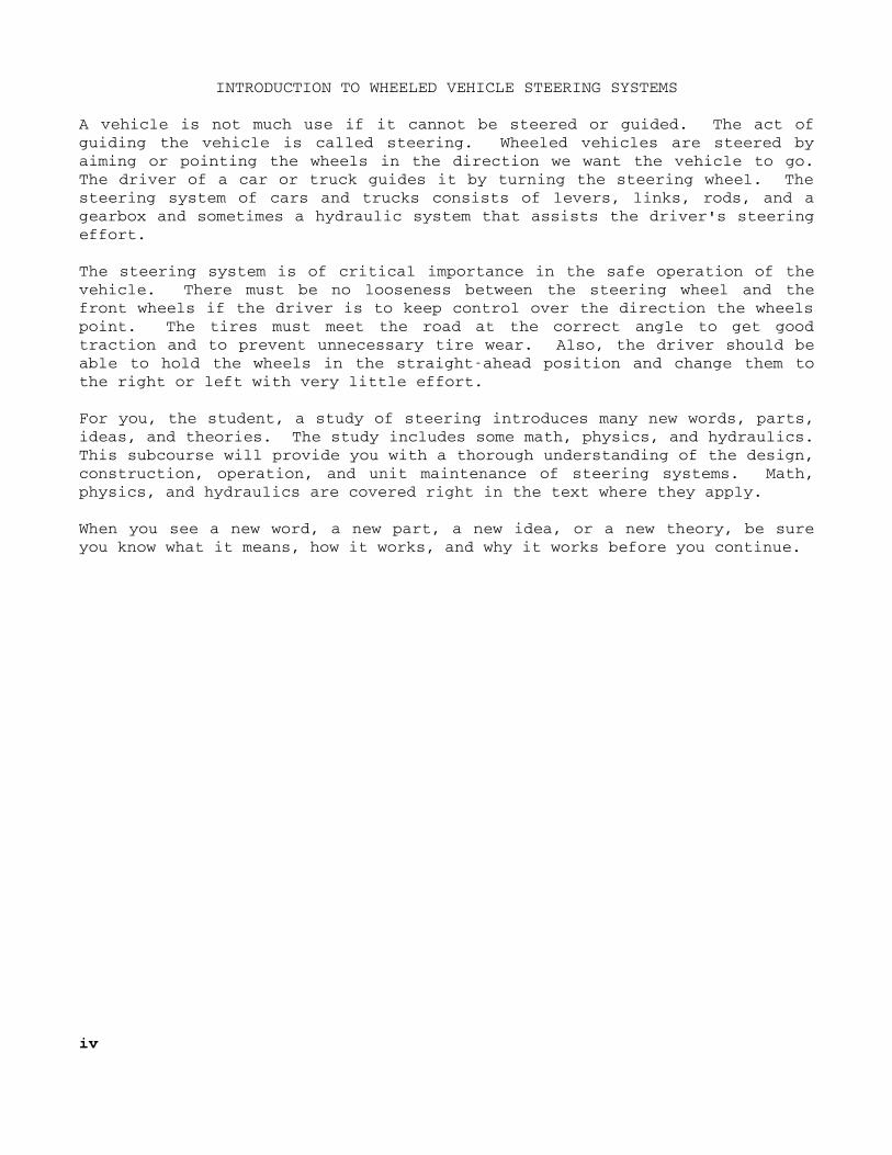
INTRODUCTION TO WHEELED VEHICLE STEERING SYSTEMS
A vehicle is not much use if it cannot be steered or guided. The act ofguiding the vehicle is called steering. Wheeled vehicles are steered byaiming or pointing the wheels in the direction we want the vehicle to go.The driver of a car or truck guides it by turning the steering wheel. Thesteering system of cars and trucks consists of levers, links, rods, and agearbox and sometimes a hydraulic system that assists the driver's steeringeffort.
The steering system is of critical importance in the safe operation of thevehicle. There must be no looseness between the steering wheel and thefront wheels if the driver is to keep control over the direction the wheelspoint. The tires must meet the road at the correct angle to get goodtraction and to prevent unnecessary tire wear. Also, the driver should beable to hold the wheels in the straightahead position and change them tothe right or left with very little effort.
For you, the student, a study of steering introduces many new words, parts,ideas, and theories. The study includes some math, physics, and hydraulics.This subcourse will provide you with a thorough understanding of the design,construction, operation, and unit maintenance of steering systems. Math,physics, and hydraulics are covered right in the text where they apply.
When you see a new word, a new part, a new idea, or a new theory, be sureyou know what it means, how it works, and why it works before you continue.
iv
Lesson 1/Learning Event 1
LESSON 1FUNDAMENTALS OF STEERING SYSTEMS
TASK
Describe the fundamentals of steering systems.
CONDITIONS
Given information about the construction and operation of mechanicalsteering gears and steering linkages and the principles of steeringgeometry.
STANDARDS
Answer 70 percent of the multiplechoice test items covering fundamentals ofsteering systems.
REFERENCES
TM 98000
Learning Event 1:DESCRIBE THE PRINCIPLES OF STEERING AND THE CONSTRUCTION AND OPERATION OFMECHANICAL STEERING GEARS AND LINKAGES
One of the most interesting features on a wheeled vehicle is the steeringsystem. The steering system consists of all the parts necessary to make thefront wheels turn in the direction we wish to go. These parts include asteering wheel, a gearbox, and all linkages and levers needed to control thefront wheels.
Steering systems are carefully designed so that the driver can, without toomuch effort, keep the vehicle going straight ahead or turn it to the rightor left. The driver must be able to easily overcome the tendency of thefront wheels to go to the right or left as a result of striking holes in theroad, rocks, stumps, or other obstructions. Obstructions try to stop thewheel that strikes them, while the other front wheel tries to keep rolling,which causes the vehicle to turn in the direction of the obstruction. Thisis called road shock. Road shock tries to jerk the steering wheel out ofthe driver's hands. Hitting obstructions makes it difficult to control thevehicle, and steering systems are designed to reduce the shock caused bystriking obstructions.
1
Lesson 1/Learning Event 1
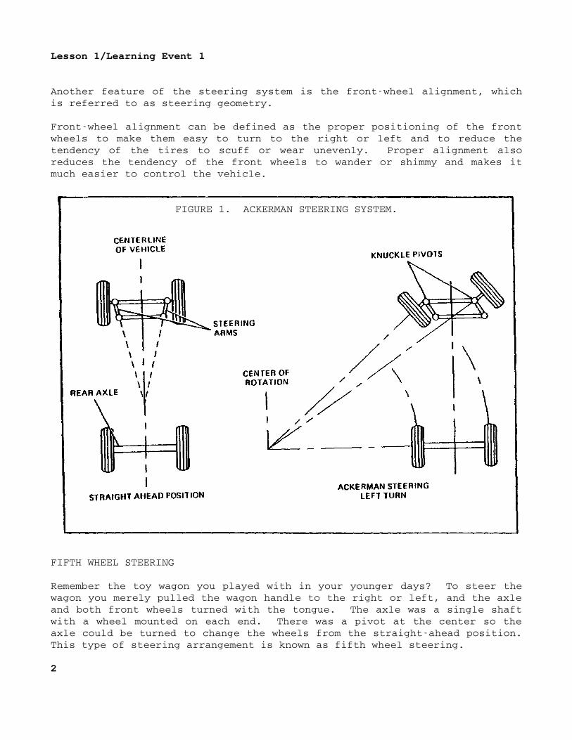
Another feature of the steering system is the frontwheel alignment, whichis referred to as steering geometry.
Frontwheel alignment can be defined as the proper positioning of the frontwheels to make them easy to turn to the right or left and to reduce thetendency of the tires to scuff or wear unevenly. Proper alignment alsoreduces the tendency of the front wheels to wander or shimmy and makes itmuch easier to control the vehicle.
FIGURE 1. ACKERMAN STEERING SYSTEM.
FIFTH WHEEL STEERING
Remember the toy wagon you played with in your younger days? To steer thewagon you merely pulled the wagon handle to the right or left, and the axleand both front wheels turned with the tongue. The axle was a single shaftwith a wheel mounted on each end. There was a pivot at the center so theaxle could be turned to change the wheels from the straightahead position.This type of steering arrangement is known as fifth wheel steering.
2
Lesson 1/Learning Event 1
Fifth wheel steering is commonly used on towed vehicles, such assemitrailers pulled by tractortrucks. The lower part of the steering pivotor fifth wheel is mounted over the center, and slightly to the front, of therear axle of the tractor. It has a kingpin lock to hold the kingpin orpivot pin of the semitrailer in the center of the fifth wheel.
Usually, the lower fifth wheel is mounted on the tractor with two pivotshafts. One shaft is positioned crosswise to the tractor; the other,lengthwise. This allows the lower fifth wheel to tip at various angles tothe tractor chassis, keeping the bearing surfaces of upper and lower halvesof the fifth wheel in firm contact as the tractor and trailer travel overunlevel roads.
The upper part of the fifth wheel consists of a pickup plate and kingpinsecured to the bottom front of the semitrailer. A groove around the kingpinallows engagement of the kingpin lock.
When the semitrailer is connected to the tractor, the bottom of the traileris higher than the tractor wheels. This is necessary because, as the truckand trailer make a turn, the entire rear axle and wheel assembly pivot underthe front of the trailer frame. On a very sharp turn, the wheel on theinside of the turn will move to about the middle under the trailer chassis.Clearance must be provided for the wheels.
3
Lesson l/Learning Event 1
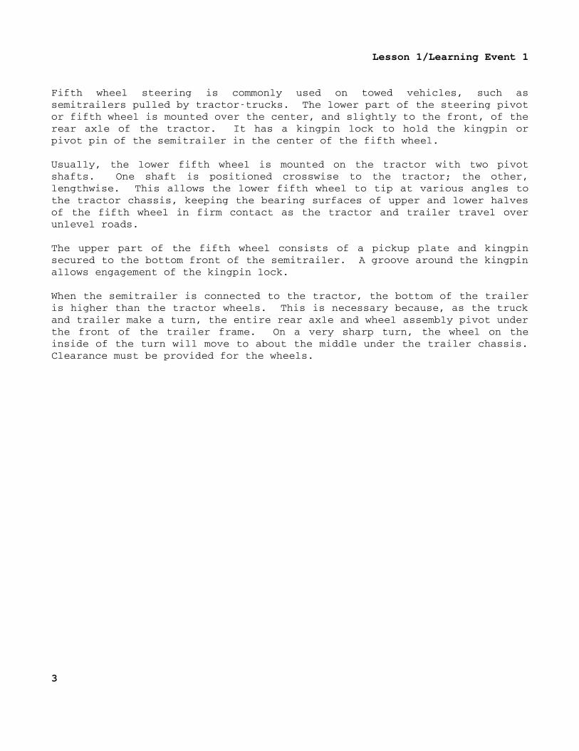
FIGURE 2. FIFTHWHEEL STEERING.
ACKERMAN STEERING
The fifthwheel method of steering is not suitable for steering a modern caror truck. The vehicle chassis would have to be too high off the ground toprovide clearance for the front wheels. Cars and trucks use a differentfront wheel arrangement. It is called the Ackerman steering method.
With this arrangement, the axle is held at a right angle to the vehicleframe and cannot pivot. The wheels change from the straightahead positionindependently on separate pivot pins or knuckle pivots at the ends of theaxle.
We will be discussing only the Ackerman steering method during the rest ofthis lesson, so let's clarify the terms that we will be using in regard towheel movements with this method. When we say "the wheels pivot," we meanthat they are changed in relation to the straightahead position when makinga right or left turn. When we say "the wheels rotate," we mean that theyturn on their spindles as the vehicle rolls forward or backward.
4
Lesson l/Learning Event 1
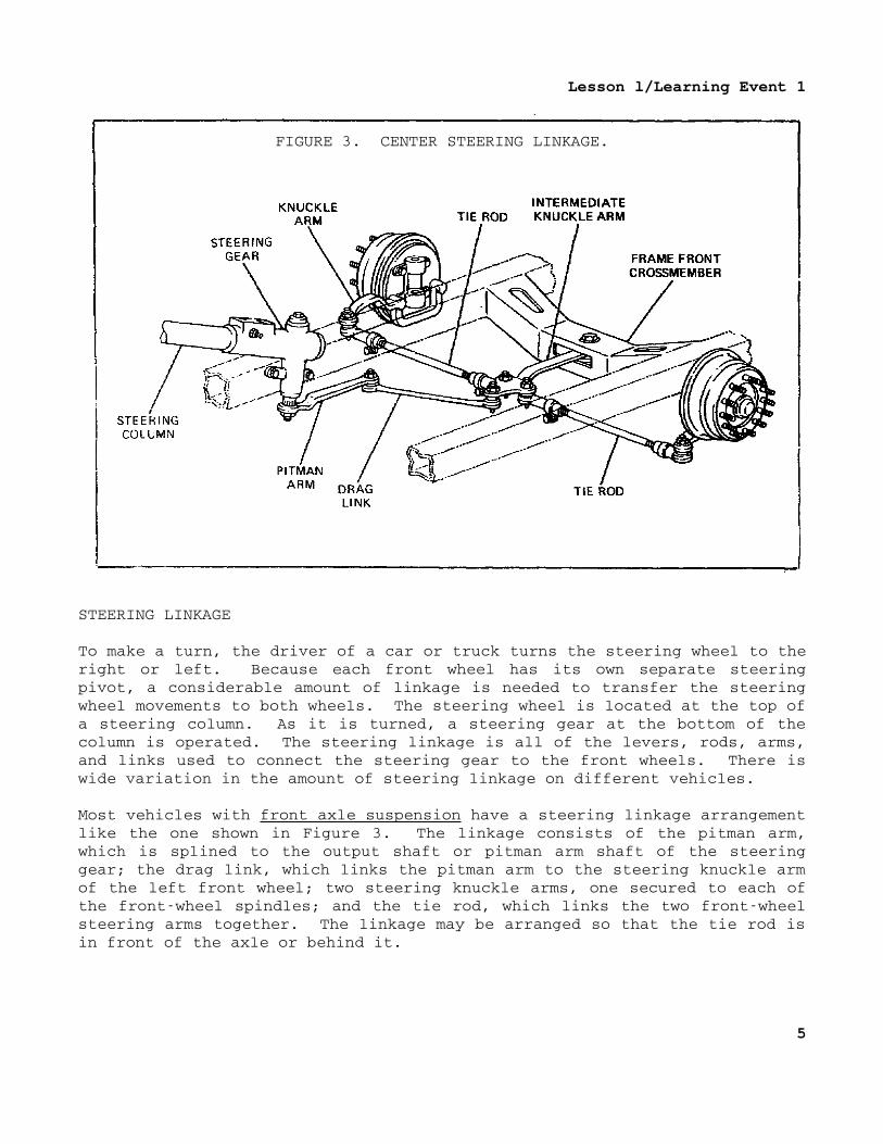
FIGURE 3. CENTER STEERING LINKAGE.
STEERING LINKAGE
To make a turn, the driver of a car or truck turns the steering wheel to theright or left. Because each front wheel has its own separate steeringpivot, a considerable amount of linkage is needed to transfer the steeringwheel movements to both wheels. The steering wheel is located at the top ofa steering column. As it is turned, a steering gear at the bottom of thecolumn is operated. The steering linkage is all of the levers, rods, arms,and links used to connect the steering gear to the front wheels. There iswide variation in the amount of steering linkage on different vehicles.
Most vehicles with front axle suspension have a steering linkage arrangementlike the one shown in Figure 3. The linkage consists of the pitman arm,which is splined to the output shaft or pitman arm shaft of the steeringgear; the drag link, which links the pitman arm to the steering knuckle armof the left front wheel; two steering knuckle arms, one secured to each ofthe frontwheel spindles; and the tie rod, which links the two frontwheelsteering arms together. The linkage may be arranged so that the tie rod isin front of the axle or behind it.
5
Lesson 1/Learning Event 1
Rotary motion of the steering wheel causes the pitman arm shaft to move backand forth in an arc, so that the drag link moves back and forth in astraight line. The drag link transmits the movement to the left steeringarm to pivot the left wheel spindle and wheel back and forth on the steeringknuckle pivots. Pivot movements of the left wheel are transmitted to theright wheel by the tie rod.
The drag link and tie rod are fastened to the pitman and steering arms byadjustable, ballsocket joints that permit swiveling action. Balltypestuds are secured to the pitman arm and the left steering arm. A housing ateach end of the drag link receives the balls. Ballsockets, coil springs,spring seats, and a screw plug in the housings hold the balls. The screwplug can be screwed in or out to tighten or loosen the joint. Lubricationfittings are provided for each joint. Shields hold the lubrication in andkeep dirt out.
The tie rod also uses ballsocket joints, but generally they are notadjustable. A spring holds the ball in its seat to prevent slack. The ballof a tie rod end has a tapered shank or stud that fits into a matchingtapered hole in the steering arm. The end of the ball stud is threaded anddrilled so it can be secured to the steering knuckle arms with a nut andcotter key.
Each tie rod is threaded and screwed onto the tie rod end. A clamp boltprevents the tie rod from turning once the ends have been installed.
One tie rod end and one end of the tie rod have lefthand threads, and theother tie rod end and the opposite end of the tie rod have righthandthreads. This is so the overall length of the tie rod assembly can beadjusted when aligning the front wheels without disconnecting either tie rodend.
If the vehicle has independent frontwheel suspension instead of an axle,the steering linkage arrangement is different. Two tie rods are required soeach wheel can be raised and lowered without affecting the steering of theother. Many different linkage arrangements are used with independentsuspension. Some are quite simple, with the linkage consisting of thepitman arm, two tie rods, and the steering arms.
6
Lesson 1/Learning Event 1
Other common arrangements add an idler arm and drag link. In thesearrangements the idler arm is mounted on the right frame rail by a bracketparallel to the pitman arm. The drag link connects the pitman arm and idlerarm so that moving the steering wheel causes both arms to swing in the samearc. Each steering arm is linked to the drag link by a separate tie rod.In this arrangement, the drag link may be called a relay rod, pitman armtoidler arm rod, and so forth.
Usually, the length of both tie rods can be adjusted independently whenaligning the front wheels. The ends on the drag links and tie rods ofvehicles with independent wheel suspension are usually not adjustable. Onsome latemodel cars, tie rod ends are lubricated for life when manufacturedand do not contain lubricating fittings.
Either threaded or rubber bushings are used at the idler armtoidler armbracket pivot. Threadedtype bushings contain both internal and externalthreads. The external threads are generally righthand threads and arescrewed into, and tightened in, a threaded hole in either the idler arm orits bracket. The internal threads are generally lefthand threads and arescrewed onto the threaded end of the arm or bracket until it bottoms andthen backed up onehalf to one turn. This leaves the idler arm free topivot on the inner threads of the bushing.
STEERING GEAR
With the steering wheel coupled directly to the pitman arm by a shaft, itwould be very hard for the driver to steer the vehicle. Something must beused between the steering wheel and pitman arm so the driver can gain amechanical advantage to make steering easier. This is the function of thesteering gear.
The principles of steering gears can be demonstrated with a bolt and a nutin the following manner. Screw the nut to the midpoint of the threads onthe bolt. Place the end of the bolt against a flat surface so it cannotmove back and forth but can be rotated. Hold the nut so it cannot rotate;then, turn the bolt. When the bolt is turned clockwise, the nut is pulledtoward the bolt's head. When the bolt is turned counterclockwise, the nutwill be moved away from the bolt's head.
Now, if we cut out a section of the nut, attach a shaft to it, and place itagainst the bolt, we can see how this principle is used in the steeringgear. With this arrangement, turning the bolt back and forth will cause thenut section to swing back and forth, turning the shaft with it.
7
Lesson 1/Learning Event 1
In a steering gear, the part that is like the bolt is called the worm. Theworm is secured to the lower end of a shaft with the steering wheel on theopposite end so that the worm and steering wheel turn together. Thesteering gear part that is like the section of a nut is called the sector,and its shaft is called the pitman arm shaft. The pitman arm is splined tothe pitman arm shaft.
The steering gear worm (bolt) and the sector (nut section) are machined sothat there is very little lash or clearance between their threads in themidposition. However, as the worm is turned to steer the vehicle either tothe right or the left, the amount of lash increases. This makes up for theunequal wear that occurs in normal use. Vehicles are operated in thestraightahead position most of the time, so most of the wear is in thecenter of the steering gear worm.
It requires 2 1/2 to 3 1/2 turns of the steering wheel and worm to move thepitman arm shaft through its entire allowable movement, an arc of about 70°.That pivots the front wheels from a hard turn in one direction to a hardturn in the opposite direction. The steering wheel has to be turned fartherbecause of the mechanical advantage gained by the worm and sector. Moststeering gears are designed so that they provide more mechanical advantagein the midposition than when turned to the extreme right or left, so theyare said to have a "variable" ratio.
Many different kinds of steering gears are used, but they all work in aboutthe same manner.
8
Lesson 1/Learning Event 1
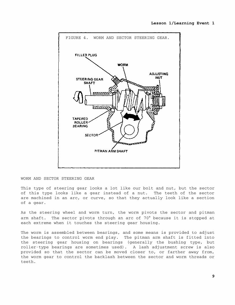
FIGURE 4. WORM AND SECTOR STEERING GEAR.
WORM AND SECTOR STEERING GEAR
This type of steering gear looks a lot like our bolt and nut, but the sectorof this type looks like a gear instead of a nut. The teeth of the sectorare machined in an arc, or curve, so that they actually look like a sectionof a gear.
As the steering wheel and worm turn, the worm pivots the sector and pitmanarm shaft. The sector pivots through an arc of 70° because it is stopped ateach extreme when it touches the steering gear housing.
The worm is assembled between bearings, and some means is provided to adjustthe bearings to control worm end play. The pitman arm shaft is fitted intothe steering gear housing on bearings (generally the bushing type, butrollertype bearings are sometimes used). A lash adjustment screw is alsoprovided so that the sector can be moved closer to, or farther away from,the worm gear to control the backlash between the sector and worm threads orteeth.
9
Lesson 1/Learning Event 1
The worm and sector steering gear is very simple in construction. Thismakes it cheap to build and easy to maintain. A disadvantage is that it hasa lot of friction because of the sliding action between the worm and sectorgear teeth.
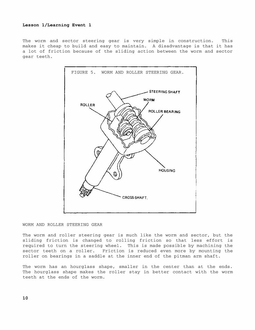
FIGURE 5. WORM AND ROLLER STEERING GEAR.
WORM AND ROLLER STEERING GEAR
The worm and roller steering gear is much like the worm and sector, but thesliding friction is changed to rolling friction so that less effort isrequired to turn the steering wheel. This is made possible by machining thesector teeth on a roller. Friction is reduced even more by mounting theroller on bearings in a saddle at the inner end of the pitman arm shaft.
The worm has an hourglass shape, smaller in the center than at the ends.The hourglass shape makes the roller stay in better contact with the wormteeth at the ends of the worm.
10
Lesson 1/Learning Event 1
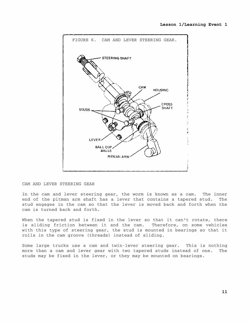
FIGURE 6. CAM AND LEVER STEERING GEAR.
CAM AND LEVER STEERING GEAR
In the cam and lever steering gear, the worm is known as a cam. The innerend of the pitman arm shaft has a lever that contains a tapered stud. Thestud engages in the cam so that the lever is moved back and forth when thecam is turned back and forth.
When the tapered stud is fixed in the lever so that it can't rotate, thereis sliding friction between it and the cam. Therefore, on some vehicleswith this type of steering gear, the stud is mounted in bearings so that itrolls in the cam groove (threads) instead of sliding.
Some large trucks use a cam and twinlever steering gear. This is nothingmore than a cam and lever gear with two tapered studs instead of one. Thestuds may be fixed in the lever, or they may be mounted on bearings.
11
Lesson 1/Learning Event 1
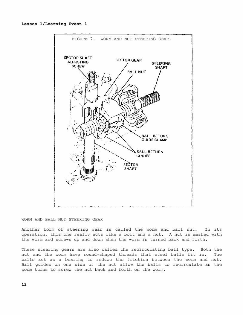
FIGURE 7. WORM AND NUT STEERING GEAR.
WORM AND BALL NUT STEERING GEAR
Another form of steering gear is called the worm and ball nut. In itsoperation, this one really acts like a bolt and a nut. A nut is meshed withthe worm and screws up and down when the worm is turned back and forth.
These steering gears are also called the recirculating ball type. Both thenut and the worm have roundshaped threads that steel balls fit in. Theballs act as a bearing to reduce the friction between the worm and nut.Ball guides on one side of the nut allow the balls to recirculate as theworm turns to screw the nut back and forth on the worm.
12
Lesson 1/Learning Event 1
The nut has teeth on one side that mesh with the sector and turn the pitmanarm shaft back and forth as the nut is moved back and forth. As with allthe rest of the steering gears described, the end play of the worm and thebacklash between the nut and sector teeth are adjustable.
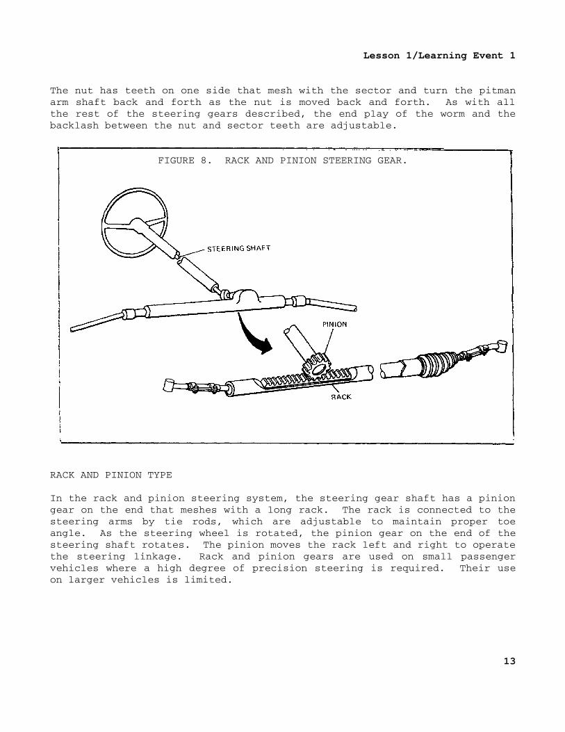
FIGURE 8. RACK AND PINION STEERING GEAR.
RACK AND PINION TYPE
In the rack and pinion steering system, the steering gear shaft has a piniongear on the end that meshes with a long rack. The rack is connected to thesteering arms by tie rods, which are adjustable to maintain proper toeangle. As the steering wheel is rotated, the pinion gear on the end of thesteering shaft rotates. The pinion moves the rack left and right to operatethe steering linkage. Rack and pinion gears are used on small passengervehicles where a high degree of precision steering is required. Their useon larger vehicles is limited.
13
Lesson 1/Learning Event 1
FOURWHEEL DRIVING AND STEERING
Four-wheel drive
A construction in which all four wheels of the vehicle drive is used on manymilitary vehicles. A universal joint is used at the end of the axle shaftso that the wheel is free to pivot at the end of the axle while being driventhrough the axle. The end of the axle housing encloses this universal jointand has vertical trunnion pins that act as a steering knuckle pivot. Thewheels, mounted on steering knuckles attached to these trunnion pivots, arefree to turn around the pivots at the same time they are driven throughuniversal joints on the inner axle shaft. Steering knuckle arms are mountedon the steering knuckles so that the wheels can be turned around thetrunnion steering pivots by the steering linkage.
Four-wheel steering
All four wheels can be steered from the steering wheel by connecting thesteering linkage of these wheels to the pitman arm. The rear wheels areconnected by knuckle arms and a tie rod. Because the rear wheels must beturned in the opposite direction to the front wheels to travel in the samearcs around the center of rotation, the drag links to the front and rearwheel steering linkage cannot be connected directly to the steering geararm. The drag link to the front wheels must move forward while the draglink to the rear wheels moves rearward and vice versa. To accomplish this,an intermediate steering gear arm is pivoted on the frame sidemember nearthe middle of the vehicle. The drag links are connected to opposite ends ofthis arm. As it is turned by direct connection to the pinion arm (by meansof an intermediate link), the front and rear drag links are moved inopposite directions.
14
Lesson 1/Learning Event 2
Learning Event 2:DESCRIBE THE PRINCIPLES OF WHEEL ALIGNMENT
It is not enough to merely place the front wheels on spindles and steeringknuckles so they can roll and so the driver can pivot them to the right orleft. The wheels must be pointed or aligned just right if the vehicle is tosteer properly.
Wheel alignment (steering geometry) is the positioning of the front wheelsto best control the forces of gravity, friction, momentum, and centrifugalforce. All of these forces tend to make steering difficult.
Perfectly aligned wheels do not wander, weave, shimmy, or scuff tires, yetthey are easy to pivot when making a turn. In addition, the front wheelsshould straighten out if the driver releases the steering wheel afterturning a corner.
To do all this, the front wheels and their pivot points are not positionedstraight up and down or straight ahead. They are tilted at various angles.There are five different angles involved in the alignment of the frontwheels: caster, camber, kingpin inclination, toein, and toeout.Definitions of these angles and their effects are given in the followingparagraphs.
15
Lesson 1/Learning Event 2
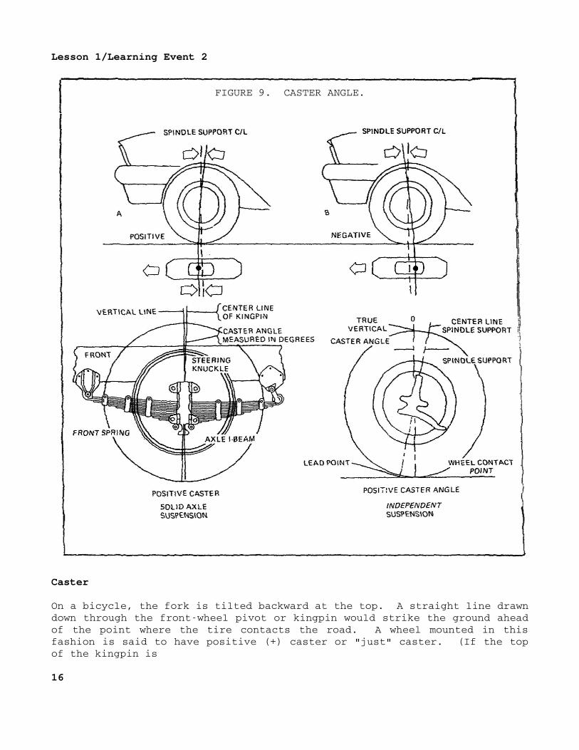
FIGURE 9. CASTER ANGLE.
Caster
On a bicycle, the fork is tilted backward at the top. A straight line drawndown through the frontwheel pivot or kingpin would strike the ground aheadof the point where the tire contacts the road. A wheel mounted in thisfashion is said to have positive (+) caster or "just" caster. (If the topof the kingpin is
16
Lesson 1/Learning Event 2
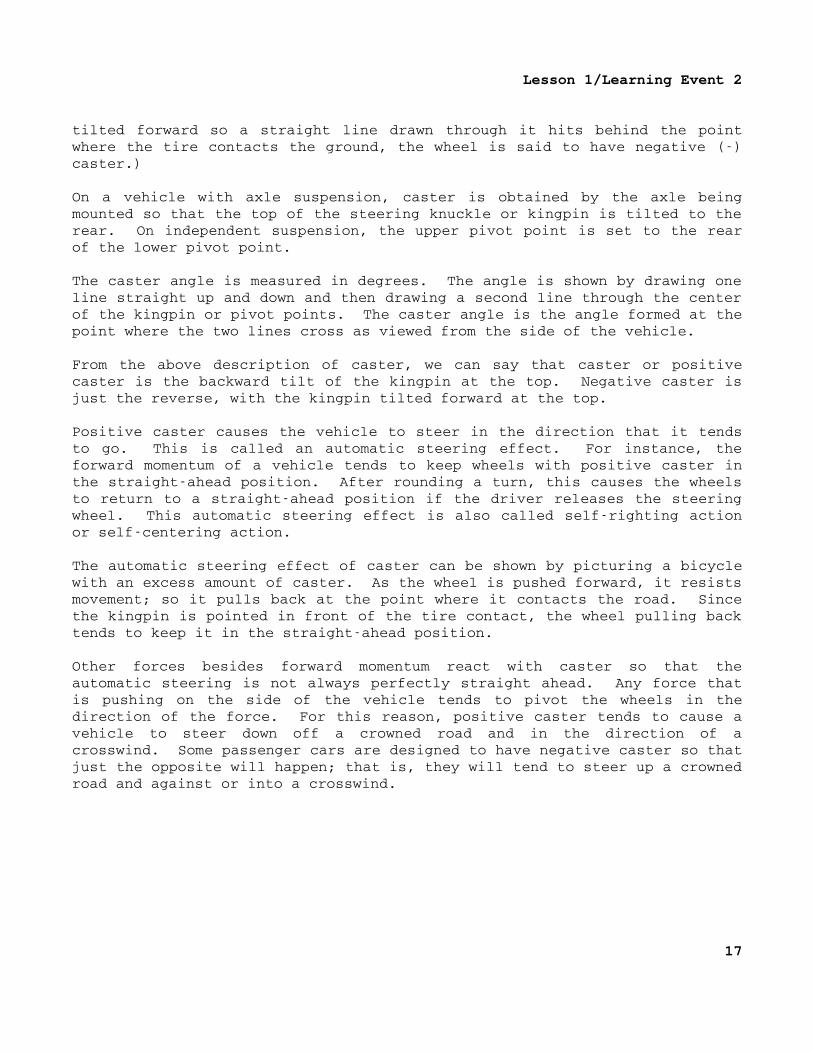
tilted forward so a straight line drawn through it hits behind the pointwhere the tire contacts the ground, the wheel is said to have negative ()caster.)
On a vehicle with axle suspension, caster is obtained by the axle beingmounted so that the top of the steering knuckle or kingpin is tilted to therear. On independent suspension, the upper pivot point is set to the rearof the lower pivot point.
The caster angle is measured in degrees. The angle is shown by drawing oneline straight up and down and then drawing a second line through the centerof the kingpin or pivot points. The caster angle is the angle formed at thepoint where the two lines cross as viewed from the side of the vehicle.
From the above description of caster, we can say that caster or positivecaster is the backward tilt of the kingpin at the top. Negative caster isjust the reverse, with the kingpin tilted forward at the top.
Positive caster causes the vehicle to steer in the direction that it tendsto go. This is called an automatic steering effect. For instance, theforward momentum of a vehicle tends to keep wheels with positive caster inthe straightahead position. After rounding a turn, this causes the wheelsto return to a straightahead position if the driver releases the steeringwheel. This automatic steering effect is also called selfrighting actionor selfcentering action.
The automatic steering effect of caster can be shown by picturing a bicyclewith an excess amount of caster. As the wheel is pushed forward, it resistsmovement; so it pulls back at the point where it contacts the road. Sincethe kingpin is pointed in front of the tire contact, the wheel pulling backtends to keep it in the straightahead position.
Other forces besides forward momentum react with caster so that theautomatic steering is not always perfectly straight ahead. Any force thatis pushing on the side of the vehicle tends to pivot the wheels in thedirection of the force. For this reason, positive caster tends to cause avehicle to steer down off a crowned road and in the direction of acrosswind. Some passenger cars are designed to have negative caster so thatjust the opposite will happen; that is, they will tend to steer up a crownedroad and against or into a crosswind.
17
Lesson 1/Learning Event 2
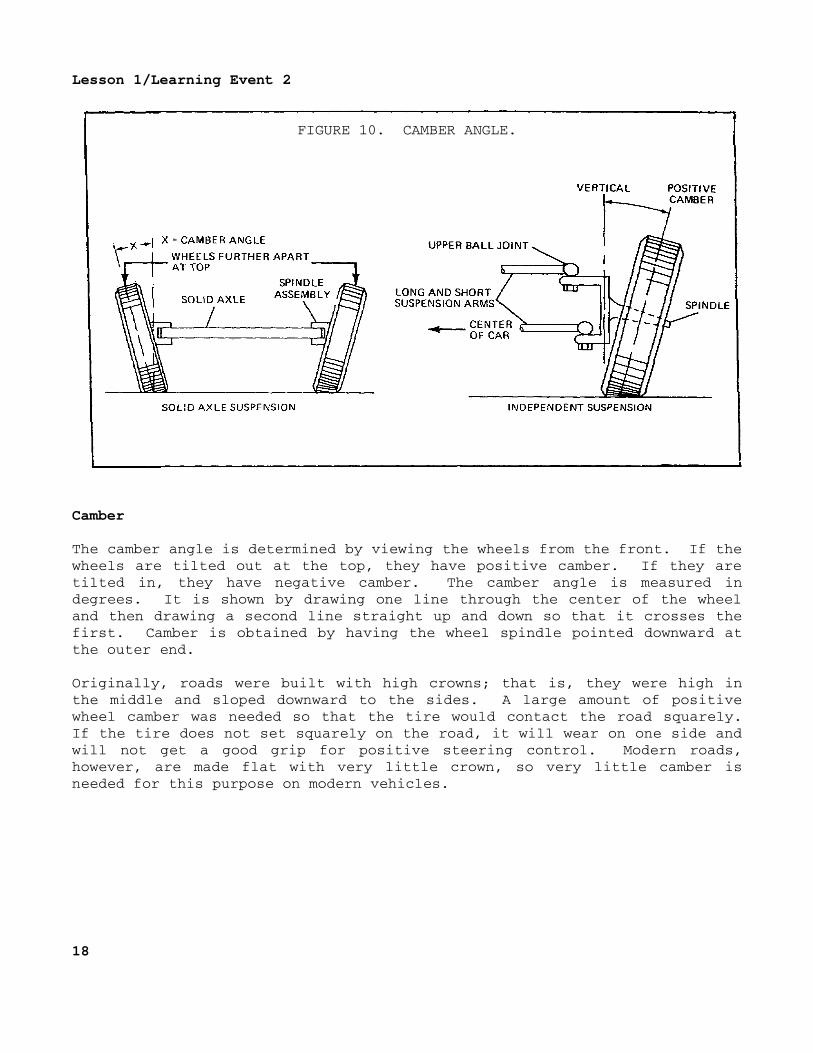
FIGURE 10. CAMBER ANGLE.
Camber
The camber angle is determined by viewing the wheels from the front. If thewheels are tilted out at the top, they have positive camber. If they aretilted in, they have negative camber. The camber angle is measured indegrees. It is shown by drawing one line through the center of the wheeland then drawing a second line straight up and down so that it crosses thefirst. Camber is obtained by having the wheel spindle pointed downward atthe outer end.
Originally, roads were built with high crowns; that is, they were high inthe middle and sloped downward to the sides. A large amount of positivewheel camber was needed so that the tire would contact the road squarely.If the tire does not set squarely on the road, it will wear on one side andwill not get a good grip for positive steering control. Modern roads,however, are made flat with very little crown, so very little camber isneeded for this purpose on modern vehicles.
18
Lesson 1/Learning Event 2
Some camber is generally desirable, even with flat roads, because it movesthe point of contact between the tire and the road more directly under, andcloser to, the steering knuckle pivot. This makes the wheels easier topivot and reduces the amount of road shock that is sent to the vehiclesuspension and steering linkage when the wheels hit bumps. It also placesmost of the load on the large inner wheel bearing.
The amount of camber must be carefully considered when designing a vehicleto avoid some bad effects. If you ever rolled a tire by hand, you soonlearned that you did not have to turn the tire in order to turn a corner.All you had to do was to tilt (camber) the tire to one side, and it rolledaround the corner like a cone. This is not desirable for the wheels of avehicle. The cone effect of positive camber tries to pivot the wheels outon a vehicle.
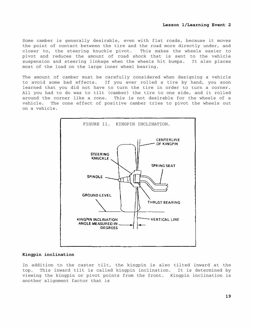
FIGURE 11. KINGPIN INCLINATION.
Kingpin inclination
In addition to the caster tilt, the kingpin is also tilted inward at thetop. This inward tilt is called kingpin inclination. It is determined byviewing the kingpin or pivot points from the front. Kingpin inclination isanother alignment factor that is
19
Lesson 1/Learning Event 2
measured in degrees. It can be shown by drawing two lines that cross toform an angle. One line passes through the center of the pivot points orkingpin and the other line is straight up and down.
Notice that the kingpin is tilted in the opposite direction from thecambered wheel. Proper kingpin inclination can reduce the amount of camberneeded to place the point of tire contact with the ground under the steeringknuckle pivot. If the front wheels are aligned properly, lines drawnthrough the center of the cambered wheel and the kingpin should hit theground close to where the tire contacts the ground. (The combination of thekingpin inclination angle and the wheel camber angle is known as theincluded angle.)
20
Lesson 1/Learning Event 2
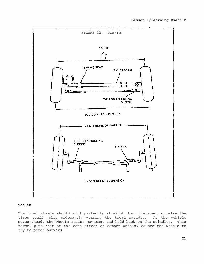
FIGURE 12. TOEIN.
Toe-in
The front wheels should roll perfectly straight down the road, or else thetires scuff (slip sideways), wearing the tread rapidly. As the vehiclemoves ahead, the wheels resist movement and hold back on the spindles. Thisforce, plus that of the cone effect of camber wheels, causes the wheels totry to pivot outward.
21
Lesson 1/Learning Event 2
That is, the left wheel tries to pivot to the left and the right wheel tothe right. The wheels are able to pivot out to some extent because thesteering knuckles and tie rod ends must have a slight amount of clearance topermit easy steering. To offset this, the wheels are aligned with a slightamount of toein.
Toedin wheels are closer together at the front than at the rear. Toein ismeasured in inches. The amount is found by measuring the distance betweenthe front wheels, first at the front outer edges of the tires and then attheir rear outer edges. The amount of toein is the difference in the twomeasurements, which is usually about 1/32 inch to 1/8 inch. If the wheelsare closer together in the rear than in the front, they are said to be toedout. The amount of toein can be adjusted by shortening or lengthening theadjustable tie rod.
Ideally, the toein, measured with the vehicle standing still, shouldexactly equal the amount the wheels pivot outward when the vehicle runs atcruising speed. Then, the wheels will roll perfectly straight ahead atcruising speed with no side slippage.
Toe-out
Side slippage of the tires must also be considered when turning a corner, toensure positive steering control and to prevent excessive tire wear. Eachwheel must be at a 90° angle to the center of rotation if it is to rolleasily and not scuff the tread of the tire.
This is no problem forfifth wheel steering. Pivoting the axle assemblymoves the front wheel at the outer edge of the turning radius ahead of theinner wheel, and the 90° angle is obtained. With Ackerman steering,however, the wheels must toeout on a turn.
With Ackerman steering, when turning a corner, one straight line cannot beextended from the center of both front wheels. Instead, two lines must beextended at different angles in order to pass through the center of thewheels. For both wheels to be at a 90° angle to the center of rotation, theinner wheel must pivot more than the outer wheel. (The exact difference inthe amount that the wheels should pivot is the value of the angle formed bythe lines extended from the center of rotation through the center of thefront wheels. For instance, if the lines form a 3° angle, the inner wheelmust pivot 3° more than the outer wheel.)
22

Lesson 1/Learning Event 2
Also, the size of the circles that the front wheels travel shows the needfor toeout: The outside wheel is traveling in a larger circle than theinside wheel. In order to travel in a smaller circle, the inner wheel musttherefore pivot more than the outer wheel. The sharper the turn, thegreater the amount of toeout needed.
The need for the wheels to be toedin in the straightahead position andthen toedout on turns is a difficult design problem. The problem is madeeven harder by the fact that when the vehicle is turned to the left, theleft wheel should pivot more, but when turned to the right, the right wheelshould pivot more. Let's take a close took at the steering linkage to seehow this is done.
With the steering arms set at right angles (90°) to the wheel spindles, toeout on turns could not be obtained. Both steering arms would pivot the samenumber of degrees when the tie rod moved a given distance lengthwise to theaxle. For example, if the left steering arm and spindle pivot 42°, the tierod moves the right steering arm the same distance, pivoting it 42°. Bothsteering arms move the same distance lengthwise to the axle and pivot onidentical segments of an arc.
However, the steering arms are not at right angles to the spindle. If thetie rod is behind the axle, the steering arms point inward when the wheelsare in the straightahead position. With this arrangement, the wheels willtoeout on turns because the steering arms do not pivot the same amount whenthey move the same amount lengthwise to the axle. For instance, if the leftspindle pivots 50° to the left, the right spindle pivots 42°. However, bothspindles move the same distance lengthwise to the axle, because the steeringarms are pivoted on different segments of an arc.
Toeout is generally spoken of as the number of degrees over 20 that theinner wheel is turned when the outer wheel is turned 20°. For instance, ifthe right wheel is turned 20° and the left wheel 23° on a left turn, the toeout is 3°.
23
Lesson 1/Learning Event 3
Learning Event 3:DESCRIBE THE INSPECTION PROCEDURES FOR MECHANICAL STEERING SYSTEMS
INTRODUCTION
The steering gear is one of the most used controls on the vehicle. If thesteering operates improperly, the operator loses no time in reporting theproblem because a faulty steering gear is a gamble with life.
As a wheeled vehicle mechanic, you are responsible for some of themaintenance on steering systems. This maintenance includes troubleshootingand minor repairs on the steering gears.
Another maintenance function you are responsible for is inspecting theoverall condition of steering gears. This is probably the most importantmaintenance function of all.
COMMON STEERING PROBLEMS
Steering systems, like all mechanical parts, develop various problems. Someof these problems are "unwanted factors" that affect the steering. Examplesof these factors are wandering, shimmy, and hard steering. As a wheeledvehicle mechanic, you must know how to locate the causes of these problems.Not all steering problems are caused by the steering gear.
Hard steering
Hard steering causes the operator to have trouble turning the wheel andcauses the operator to have to fight the wheel to keep traveling straightdown the road. It can be caused by lack of lubrication, bent parts, andimproper adjustments.
Loose steering
This is caused by steering parts that are worn, broken, or out ofadjustment. The driver must turn the wheel excessively to steer thevehicle.
Wandering
The vehicle wanders over the road. A vehicle should travel straight down alevel road with little or no guidance by the operator. If the vehiclewanders, the operator must continuously turn (fight) the steering wheel tokeep the vehicle traveling straight.
24
Lesson 1/Learning Event 3
Shimmy
Shimmy means the front wheels move in and out or vibrate at certain speeds.Shimmy is definitely noticeable in the steering wheel. If the shimmy is badenough, it can be very dangerous because its force can break some of thesteering parts. Shimmy can be caused by wheels and tires that are out ofbalance or bent wheels, as well as other causes. Shimmy will be worse ifthe steering parts are worn or out of adjustment.
Wheel tramp
Wheel tramp means the wheels are bouncing up and down. This also isnoticeable in the steering wheel, but as a vibration, whereas shimmy triesto turn the steering wheel back and forth. Wheel tramp, like shimmy, isalso caused by wheels and tires that are out of balance. However, the outofbalance portion is equal across the wheel or tire. This causes the wheelto move straight up and down rather than sideways as in shimmy. Wheeltramp, like shimmy, will be worse on a vehicle if some of the parts areloose, worn, or improperly adjusted.
Vehicle pulls to one side
This can have many causes; however, the mechanical steering gear does notcause this malfunction. The causes range from low tire pressure on one sideof the vehicle to a bent frame.
Erratic steering
This means the steering does not act the same all the time. For example,the vehicle could pull to the right for a while and then start pulling tothe left. If the vehicle pulls to one side when the brakes are applied, thevehicle is also considered to have erratic steering. One cause of erraticsteering is a load that moves about or too much load on one portion of thebody, especially the rear.
Rough steering
The steering wheel does not turn smoothly. This could be caused by damagedcomponents in the steering gear or steering linkage. Damaged steering gearcomponents could be a pitted worm (helical cam, 2 1/2ton) or roller orlever pins. Loose or pitted knuckle support bearings could also cause theproblem. A quick way to isolate the trouble is to first disconnect thesteering gear from the rest of the steering mechanism and turn the steeringwheel. If the roughness is still there, the trouble is in the steeringgear.
25
Lesson 1/Learning Event 3
Drive
The vehicle, when turned in either direction, tries to turn more rapidlythan the operator intends. This can be caused by bent, loose, or brokenparts. This is especially true if the steering gear assembly is loose onthe frame.
Wandering and drive can both be caused by loose steering parts, and severalmalfunctions have the same symptoms. For example, hard steering andwandering have the same symptomthe operator must "fight" the steeringwheel.
The good troubleshooter always makes a complete inspection of the componentsbefore removing or replacing any parts.
STEERING GEAR INSPECTION
Description of steering gear (1/4-ton truck M151)
This steering gear assembly is the wormandroller type. The roller has twoteeth that mesh with the worm, so it is usually called a two or doubletooth roller. The steering gear is mounted on the body frame left siderail. The steering column is supported by a bracket attached to theinstrument panel.
The steering gear worm gear is pressed on the steering shaft. Two taperedroller bearings support and prevent endwise movement (thrust) of the wormand shaft.
A steel trunnion pin attaches the double roller to the sector shaft. Thesector shift is mounted in bushingtype bearings pressed into the steeringgear housing. An adjustment screw engaged in the sector shaft is threadedinto the cover and controls sector shaft end play as well as the lash(movement) between the teeth of the worm and the roller. Adjustment of theworm thrust bearing is made by installing or removing gaskets of variousthicknesses between the gear housing and the housing cap.
A balltype bearing pressed into the steering column tube supports the shaftat the steering wheel end.
The pitman arm and the steering wheel have fluted serrations (splines), withone serration being double width. The doublewidth splines match blindsplines on the sector shaft and the steering shaft to ensure correctinstallation.
26
Lesson 1/Learning Event 3
Inspection procedures
Examine the steering column and steering wheel to see if they are bent,cracked, or damaged in any way.
Look for leaking seals and gaskets. There are three oil seals in thissteering gear. There are also two gaskets that can leak. Even if the sealsand gaskets are not leaking, check the lube level in the steering gearhousing.
Check the mounting brackets and bolts for secure mounting. To do this, youhave to do more than look; use a wrench to see if the bolts are tight.
Check for too much free play (slack) in the steering system. Remember thatsteering gears are designed to have very little free play when the wheelsare straight ahead. This means that, when the steering wheel is in thecenter of its travel, there should be no noticeable free play. This centerpoint is called the high point or midposition. When the steering gear isnot on the high point, some free play is normal.
Next, roadtest the vehicle and check for binding, wander, or shimmy whilethe vehicle is moving forward.
If any of these malfunctions show up, they may be caused by the steeringgear or by some of the linkage.
Let's suppose that you notice binding. It will now be necessary to take theload off the steering gear by disconnecting the steering linkage from thesteering. If the binding is still present when the steering wheel is turnedafter the linkage is disconnected, the trouble is in the steering gear.That is as far as a unit mechanic can go, because adjusting or replacing thesteering gear on this vehicle is a job for the next level of maintenance.
27
Lesson 1
PRACTICE EXERCISE
1. What type of steering is used on modern cars and trucks?
a. Ackermanb. Radialc. Fifth wheel
2. The front wheels of a vehicle rotate on their
a. pivots.b. spindles.c. steering knuckles.
3. What direction must the kingpin be tilted to have positive caster?
a. Outwardb. Forwardc. Backward
4. The angle formed by the steering are and wheel spindle controls the
a. toein.b. toeout.C. kingpin inclination.
5. The term "shimmy" means that the front wheels
a. move in and out.b. move up and down.c. wander.
28

Lesson 1
This page intentionally left blank.
29
Lesson 1
ANSWERS TO PRACTICE EXERCISE
1. a (page 4)
2. b (page 4)
3. c (page 17)
4. b (page 23)
5. a (page 25)
30
Lesson 2/Learning Event 1
LESSON 2FUNDAMENTALS OF POWER STEERING
TASK
Describe the fundamentals of power steering systems.
CONDITIONS
Given information about the principles, operation, construction, andinspection of power steering systems.
STANDARDS
Answer 70 percent of the multiplechoice test items covering fundamentals ofsteering systems.
REFERENCES
TM 98000
Learning Event 1:DESCRIBE THE CONSTRUCTION AND OPERATION OF POWER STEERING SYSTEMS
Steering gears provide a mechanical advantage ratio of 11:1 or 12:1 forlight cars and up to 18:1 or more for heavy trucks. More mechanicaladvantage is desired to make some heavy vehicles easier to steer. This isnot always practical though, because it requires an excessive amount ofturning at the steering wheel to pivot the front wheels.
To reduce the amount of effort required to turn the wheels withoutincreasing the amount that the steering wheel is turned, power steering isused.
The term "power steering" is well known because hydraulic power steering iswidely used on passenger cars.
A hydraulic power steering system consists of a doubleaction powercylinder, pump, reservoir, valves, and the connecting lines and fittings.
The power steering system reduces the effort required to turn the steeringwheel. This task is accomplished by an auxiliary power network incorporatedin the steering system.
31
Lesson 2/Learning Event 1
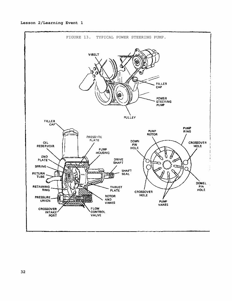
FIGURE 13. TYPICAL POWER STEERING PUMP.
32
Lesson 2/Learning Event 1
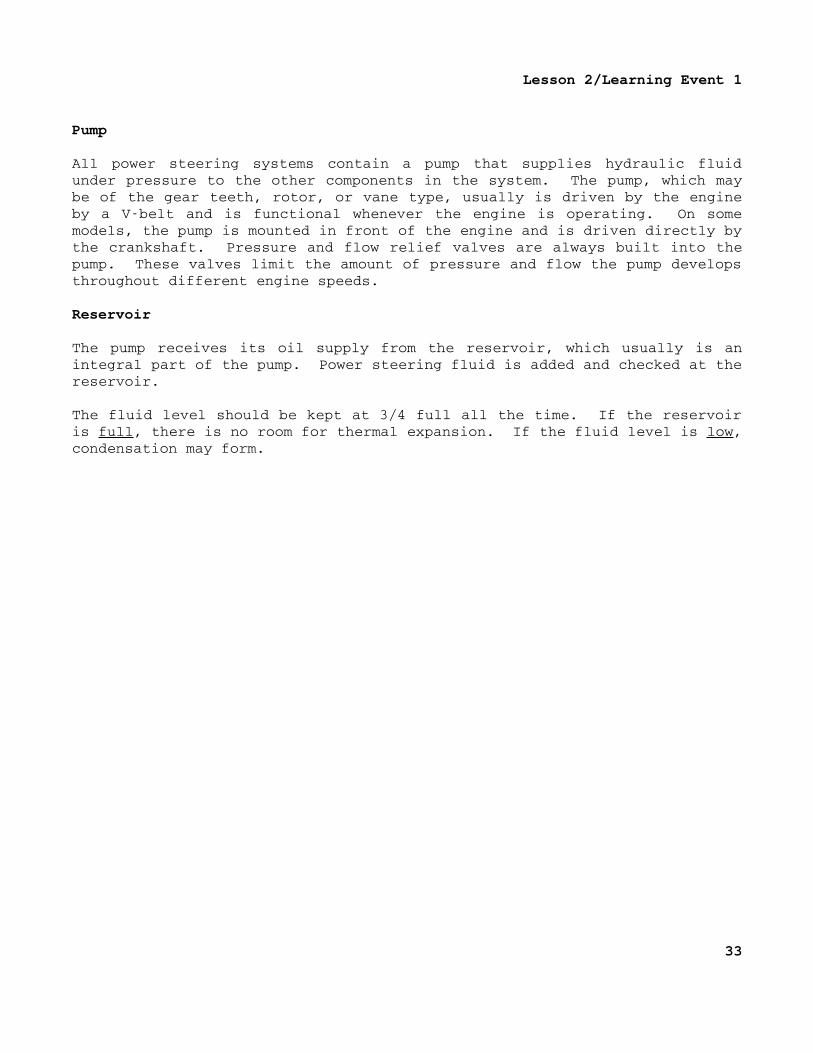
Pump
All power steering systems contain a pump that supplies hydraulic fluidunder pressure to the other components in the system. The pump, which maybe of the gear teeth, rotor, or vane type, usually is driven by the engineby a Vbelt and is functional whenever the engine is operating. On somemodels, the pump is mounted in front of the engine and is driven directly bythe crankshaft. Pressure and flow relief valves are always built into thepump. These valves limit the amount of pressure and flow the pump developsthroughout different engine speeds.
Reservoir
The pump receives its oil supply from the reservoir, which usually is anintegral part of the pump. Power steering fluid is added and checked at thereservoir.
The fluid level should be kept at 3/4 full all the time. If the reservoiris full, there is no room for thermal expansion. If the fluid level is low,condensation may form.
33
Lesson 2/Learning Event 1
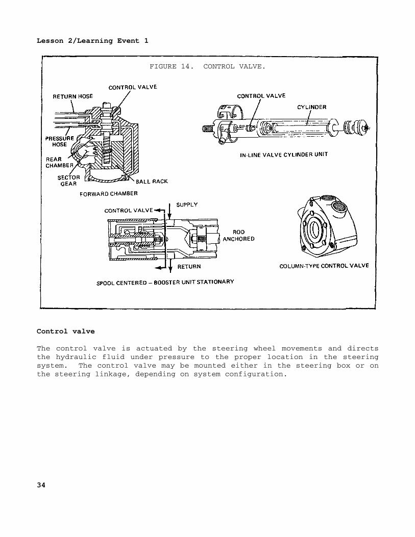
FIGURE 14. CONTROL VALVE.
Control valve
The control valve is actuated by the steering wheel movements and directsthe hydraulic fluid under pressure to the proper location in the steeringsystem. The control valve may be mounted either in the steering box or onthe steering linkage, depending on system configuration.
34
Lesson 2/Learning Event 1
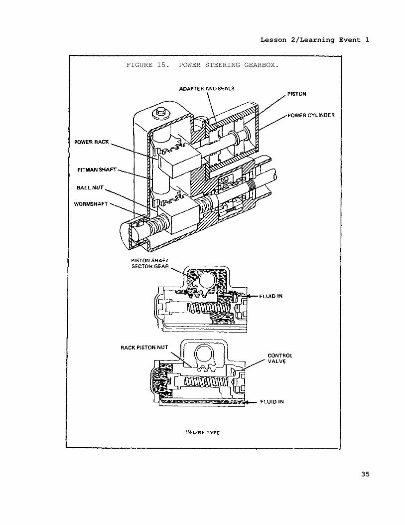
FIGURE 15. POWER STEERING GEARBOX.
35
Lesson 2/Learning Event 1
Gearbox
The gearbox in an integral power steering system is basically a manualgearbox adapted to include a power assist package. Integral power steeringgearboxes are of two types: offset and inline.
The offset type has a recirculatingball gearbox with a rack meshed to thepitman sector gear above or on the opposite side of the ball nut. The powersteering force is developed in the power piston, which is offset from theworm and nut and attached to the rack.
The inline design uses the recirculating ballnut assembly as a powerpiston. In this design, the ball nut is sealed inside a cylindrical portionof the steering gear housing. The power steering effect is produced byalternately pressurizing either side of the power piston.
Hydraulic cylinder
The hydraulic cylinder used on the semiintegral and integral power steeringsystems is located on the steering linkage. The power assist is developedin the cylinder through the action of the pressurized hydraulic fluid.
The cylinder may have single or doublewall construction. The hydraulichoses connect to the ports on each end of the singlewall cylinder. Thedoublewall cylinder has connections on one end for both hoses and aninternal passageway between the walls to pressurize the other end of thecylinder. Some linkage cylinders have shuttle valves built into the piston.This valve opens at the end of the piston stroke. This feature helpseliminate full hydraulic pressure from acting on the cylinder when thepiston is bottomed by opening and allowing fluid to flow through the piston.
36
Lesson 2/Learning Event 1
OPERATION
Neutral
In the neutral position, there is no force required of the power steeringsystem to turn the wheels; therefore, the fluid under pressure must bebypassed through the system. This usually is accomplished in the controlvalve. When there is no steering force required by the driver, the spool inthe control valve is centered by springs or hydraulic pressure or both.This allows the oil to flow through the valve and back to the reservoir andallows the steering system to maintain position.
Left and right turns
As the driver starts to turn the steering wheel to make a left or rightturn, the power steering system is activated. The spool is moved off centerposition and forced to the left or right end of the control valve. Thisopens the proper passageways for the pressurized oil. The return port isalso opened, and the fluid being displaced by the piston in the cylinderreturns to the reservoir.
CONFIGURATIONS
Linkage type
In the linkage configuration, the control valve and power cylinder may beseparate parts mounted on different parts of the linkage.
Integral
The integral system incorporates the control valve and power assist into thesteering gear as a unit.
Semi-integral
The control valve on the semiintegral system is mounted to the steeringgear, and a separate hydraulic cylinder is mounted to the linkage.
37
Lesson 2/Learning Event 2
Learning Event 2:DESCRIBE THE INSPECTION AND TROUBLESHOOTING PROCEDURES FOR POWER STEERINGSYSTEMS
TROUBLESHOOTING
Hydraulic pumps, cylinders, motors, and valves are precision units. Smoothoperation depends on frequent inspections and proper servicing of hydraulicsystems. They must be kept clean, and the oil and filters must be changedas recommended in the technical manuals.
Improper operation can generally be traced to one of the following causes:
Liquid of the wrong kind or of the wrong viscosity.
Not enough liquid in the system.
Air in the hydraulic units or lines.
Damaged or worn parts.
Oil leaks, internal or external.
Dirt, water, sludge, rust, metal cuttings, or other foreign matterin the system.
Units and control linkage improperly adjusted.
Operator error.
Troubleshooters should use procedures that will lead them directly to thecause of troubles. Eliminate as much guesswork as possible. One set ofprocedures is called STOP, described as follows:
S Study the hydraulic circuit diagrams. Know what each part in thesystem is supposed to do. This is probably the most vital partof troubleshooting.
T Test, using all equipment and means available. You must knowexactly what conditions exist in the system and how it reactsbefore you can make accurate decisions.
O Organize the knowledge gained from the circuitdiagram study andhydraulic system tests; then determine the cause of the trouble.
P Perform repairs, taking time to do the job well.
38
Lesson 2/Learning Event 2
The troubleshooting section in vehicle TMs contains a list of troubles(malfunctions) of the vehicle's hydraulic systems, the probable causes ofthe troubles, and the corrective repairs that should be made. Always usethis list to aid you in troubleshooting the vehicle.
INSPECTION
Begin the inspection by checking the level and condition of the steering oiland looking for evidence of leaks.
Inspect the hydraulic pump. Look especially for signs of leaks at the pumpmounting gasket and between the pump and its cover. Tighten the mountingand cover bolts if necessary.
Examine all hydraulic hoses carefully, especially the highpressure hosesbetween the pump and the control valve and between the control valve andpower cylinder. The hoses should be secure in their clamps and not rubbingagainst other parts or components. Unless there is evidence of leaks, donot tighten any of the hose fittings.
Check the control valve for evidence of leaks and for loose valvetosteering jacket mounting bolts.
If no leaks are evident in the system, you can now add oil to the reservoirif the oil level was low when you checked it. Of course, if you find theoil dirty or mixed with water, drain the old oil and refill it with cleanoil. While the oil is draining, clean the filter screen. Keep the oillevel in the reservoir at 3/4 full to allow for expansion.
Continue your inspection by checking the steering gear itself.
Look for evidence of lubrication oil leaks around the gear housing gasketsand seals.
Check the level of the lubrication oil in the steering gear housing byremoving the filler plug in the top of the housing. If necessary, fill thehousing with the proper grade of gear oil (GO). GO is much heavier than theOE used in the hydraulic system. This makes it easy to decide whether thehydraulic system or the steering gear is at fault if there is a leak aroundthe steering gear housing.
Check the steering geartoframe bracket mounting bolts with a wrench. Alsocheck the steering columntodash panel bracket bolts for tightness.
39
Lesson 2/Learning Event 2
Start the engine, and check the hydraulic system for leaks while oilpressure is applied. Remember that high pressure is developed in the systemonly when a turning effort is applied on the steering wheel. So, have abuddy turn the steering wheel while you look for slight oil leaks. Don'thold the steering against the steering stop for more than a few seconds at atime because this can damage the hydraulic system. The relief valve willopen to prevent the pressure from going high enough to rupture lines andunits; however, the high pressure creates heat which can damage the system.
Roadtest the vehicle. Check for any tendency to wander, weave back andforth, or shimmy. Check for excessive free play, binding, and for pullingto the right or left. Check the action of the steering assist through bothright and left turns. The steering effort required should be so small thatyou can turn the steering wheel with your thumb and forefinger while thevehicle is moving.
ISOLATING FAULTS
If the road test reveals any steering faults, the next step is to find thecause. (Faults that are peculiar to the power steering system of the 5tontruck will be described.)
If the steering was hard or was binding on turns, the trouble could be thepower steering gear, steering column jacket linkage, or steering knucklepivots. To pinpoint the trouble, you will need to disconnect the steeringlinkage from the steering gear at the point where the upper drag linkconnects to the pitman arm.
To disconnect the drag link from the pitman arm, remove the cotterpin and dust shield from the upper drag link end. Unscrew the draglink adjusting plug as far as possible without removing it. Turnthe steering wheel back and forth to loosen the ball seats on thepitman arm ball stud. Then, lift the drag link from the pitman armball stud.
Use a jack and raise the front axle until both front wheels are offthe ground. Grasp one front wheel at the front and rear, and pivotthe wheels back and forth on their steering knuckles. If the wheelspivot easily, the binding is not caused by the steering knuckles orsteering linkage.
40
Lesson 2/Learning Event 2
The binding may be caused by the steering column jacket being misalignedwith the steering gear.
To check for this, loosen the mounting bracket capscrews and theclamp bolt securing the steering column jacket to the instrumentpanel. If the column is misaligned enough to cause the steeringshaft to bind, it will realign itself when the capscrews and clampare loosened. Tighten the mounting screws and clamp; then turn thesteering wheel to check for binding. If it still binds, the troubleis in the steering gear.
If the problem was hard steering with no binding, the cause is inthe hydraulic system.
If the vehicle pulled to the right or left during the road test, this faultcould be caused by unequal tire pressure or dragging brakes. On the 5tontruck, however, pulling to one side can also be caused by the hydraulicpower steering. You check for this in the following manner:
The drag link must be disconnected from the pitman arm. Make surethat the steering gear is in the midposition. Do this by turningthe steering wheel in one direction as far as it will go. Then,counting the number of turns, turn the wheel in the oppositedirection as far as it will go. Turn the wheel back half the numberof turns you counted from stop to stop.
Now, start the engine and operate it at fast idle. Without touchingthe steering wheel, watch it to see if it moves by itself. If itdoes, the power steering control valve is not centered, and it doesnot return to the neutral position. This can be caused by loosecontrol valve mounting bolts or loose cam cover bolts at the ends ofthe cam. If tightening these bolts does not correct the problem,the cause is a defective control valve or the valve is not adjustedproperly.
After the cause of trouble has been corrected, you must reconnectthe drag link to the pitman arm. When connecting the drag link,make sure that the ball stud is properly positioned between the ballseats and tighten the drag link adjusting plug until it bottoms.Then back off the adjusting plug until its slot is aligned with thefirst cotter pin hole. Install the dust shield and a new cotterpin; then, lubricate the drag link.
41
Lesson 2/Learning Event 2
If the repairs are beyond the unit level of maintenance, notify yourmaintenance sergeant so that he can arrange for the truck to berepaired by the support unit.
To isolate the fault in the hydraulic system, the repairer from the supportunit will probably use a pressure test gage set that is designed for thistask. In case you get to assist on the job, here is how it is done.
The highpressure line between the pump and control valve is disconnected atthe control valve. A tee fitting is installed on the control valve wherethe line was removed. Then, the highpressure line is connected to the teefitting. At the center of the tee, connect the pressure gage using a shorthose provided in the test kit. The hydraulic system can now be operated,and the pressures developed will be shown on the pressure gage.
Before making any pressure tests, fill the reservoir to the proper levelwith OE 10 and operate the engine until the hydraulic oil is at normaloperating temperature. If a rapid pressure buildup occurs when the engineis started, turn the engine off quickly. Look for plugged lines, fittings,and oil passages before going any farther. A plugged or partially pluggedpassage can cause pressure buildup that will burst lines and castings.
After the unit has reached normal operating temperature, turn the steeringwheel for a right turn with the engine running at 1,000 RPM. Continueturning the steering wheel until the right turn stop is reached; then, holdit tight against the stop for just a few seconds. The gage should read 750PSI for trucks with gasoline engines and between 850 and 1,000 PSI formultifuel and diesel engines.
To repeat this test in the left turn position, it may be necessary to havean assistant hold a piece of iron, 1/4inch thick, before the front axleleft turn stop. If the hydraulic power piston is allowed to travel to theend of the cylinder on a left turn, it uncovers a port that allows thepressure to escape. The 1/4inch piece of iron prevents the piston fromtraveling far enough to uncover the port.
42
Lesson 2/Learning Event 2
If the pressure is too low, another test is necessary to tell which unit isat fault, if the relief valve and pump are separate assemblies. This isdone by blocking the oil flow to the relief valve. Don't let the pressurebuild above 750 PSI when you make the pressure test with the relief valveblocked. If this test raises the pressure, the relief valve is defective.If the pressure is still too low, the pump is probably defective.
If replacing the pump does not raise the pressure, the trouble is internalleakage in the control valve or power cylinder.
If the pressure was too high with the relief valve connected properly in thesystem, the relief valve is at fault. On trucks with gasoline engines, therelief valve is replaced separately, but the entire pump must be replaced ontrucks with multifuel and Mack diesel engines.
43
Lesson 2
PRACTICE EXERCISE
1. The power steering system that incorporates the control valve, powerassist, and steering gear into a single unit is the
a. linkage type.b. integral.c. semiintegral.
2. The power steering system is activated by the
a. steering wheel.b. hydraulic pump.c. control valve.
3. Hydraulic pumps are precision units. Therefore, it is necessary toregularly change the
a. filter(s).b. drive belts.c. relief valves.
4. Condensation is most likely to form in a hydraulic reservoir when theliquid
a. level is low.b. level is high.c. is too hot.
5. What equipment is required to isolate faults in the power steeringhydraulic system?
a. Hydraulic standb. External oil pressurec. Pressure test gage
44

Lesson 2
This page intentionally left blank.
45

Lesson 2
ANSWERS TO PRACTICE EXERCISE
1. b (page 37)
2. a (page 37)
3. a (page 38)
4. a (page 33)
5. c (page 42)
46