Fundamentals on the use of Shape Memory Alloys in Soft...
26
Chapter X Fundamentals on the use of Shape Memory Alloys in Soft Robotics After 70 years from the origin of Robotics, the actuators still represent the real bottleneck for several robotic applications. The research on the field produced several technological solutions that can satisfy specific requests, but often constraining the designer into trade-offs to release other requirements that cannot be met. This phenomenon is particularly limiting when a Mechatronics approach is considered since this concentrates on achieving optimal functional synergies among the system components from the earliest conceptual stages of the design process [HAB 07]. But if the design process is driven by the obviation of the actuation limitation, optimal performances cannot be reached. In this framework a new born branch of Robotics which is now known as “Soft Robotics” deeply conveys this effect. Due to its nature and principles the importance of a Mechatronic approach to the design of soft robots will be underlined several time through this chapter. Its main peculiarity is to present the capability of a soft interaction with the environment and with the user while preserving robustness, reliability and ability of powerful active actions. It is worth mentioning that there are at least two ways to obtain a soft interaction: the stiffness control of the robot actuators that act on the compliance of the robot joints [ALB 08] and the smart use of passive soft structural materials that assure an intrinsically soft impact [TRI 08]. Even if the two approaches aim at addressing the same result, the difference is much more than a sophism: in the first case the impedance of the actuators is controlled to provide low resistance during interaction and a stiff behavior when required; in the second case, the robots are almost totally composed of soft materials thus presenting compliance Chapter written by Matteo CIANCHETTI
Transcript of Fundamentals on the use of Shape Memory Alloys in Soft...

Chapter X
Fundamentals on the use of Shape Memory Alloys in Soft Robotics
After 70 years from the origin of Robotics, the actuators still represent the real bottleneck for several robotic applications. The research on the field produced several technological solutions that can satisfy specific requests, but often constraining the designer into trade-offs to release other requirements that cannot be met. This phenomenon is particularly limiting when a Mechatronics approach is considered since this concentrates on achieving optimal functional synergies among the system components from the earliest conceptual stages of the design process [HAB 07]. But if the design process is driven by the obviation of the actuation limitation, optimal performances cannot be reached. In this framework a new born branch of Robotics which is now known as “Soft Robotics” deeply conveys this effect. Due to its nature and principles the importance of a Mechatronic approach to the design of soft robots will be underlined several time through this chapter. Its main peculiarity is to present the capability of a soft interaction with the environment and with the user while preserving robustness, reliability and ability of powerful active actions. It is worth mentioning that there are at least two ways to obtain a soft interaction: the stiffness control of the robot actuators that act on the compliance of the robot joints [ALB 08] and the smart use of passive soft structural materials that assure an intrinsically soft impact [TRI 08]. Even if the two approaches aim at addressing the same result, the difference is much more than a sophism: in the first case the impedance of the actuators is controlled to provide low resistance during interaction and a stiff behavior when required; in the second case, the robots are almost totally composed of soft materials thus presenting compliance
Chapter written by Matteo CIANCHETTI

2 ISTE Ltd.
naturally, but they can change the stiffness of part of their body when necessary by generating the right combination of internal stresses. In this chapter this second view will be considered and a particular, but already wide used, actuation technology for this kind of robots will be treated: the Shape Memory Alloys (SMAs). The main characteristics will be introduced always giving a particular emphasis on the issues related to their use in soft robots.
X.1. Introduction
Talking about SMAs one should consider a wide family of alloys which show two main peculiar characteristics, detailed in the next section: the shape memory effect (SME) and the Superelastic Effect (SE). Since 1932, when a Swedish physicist Arne Olander discovered the SME on an AuCd alloy, a growing interest on this peculiar behavior led to the production of a huge number of different alloys presenting the same effects. These include certain copper alloys (CuAlZn), nickel-titanium-based alloys and some ternary alloys such as NiTiCu and NiTiNb. But the most used and commonly available alloys are the NiTi-based alloys which present the best memory and superelasticity. Discovered in 1961, by a group of U.S. Naval Ordnance Laboratory researchers led by William Beuhler, the first commercial application is dated 1970 when Raychem Corporation’s “shrink-to-fit” pipe couplers were used to join hydraulic tubes in F-14 Tomcat.
For their own characteristics SMAs are very well known in Soft Robotics and often taken into consideration when facing the actuation strategy to be chosen. The major advantage of this technology is its very high work density: the lighter the actuators, the bigger is the resulting power/weight ratio, therefore making SMAs a valid alternative to conventional actuators. Moreover they are silent during operation and clean; they present high remotability and can be easily distributed to obtain local deformations with low driving voltages; they resist excellently to chemical corrosion and are generally biocompatible for their use in the medical field. On the other hand some drawbacks limit the use of SMAs for specific applications: even if the driving voltage can be maintained low, a relative high current is often required and it does not come with high energy efficiency (1-10%). Other disadvantages are a bandwidth limited by thermal cycles and possible arising of mechanical fatigue after a few cycles. Finally the non linearity and the wide hysteresis that characterize the thermo-mechanical behavior of the alloy generate several control issues. In fact, even if the SME of these alloys is quite trivial to observe, its correct and advanced use requires a deep knowledge of the intrinsic driving mechanisms.
Despite this, the interest on this technology still remains very high for its potential use as artificial muscles and it is proved by the tremendous number of past

Fundamentals on the use of Shape Memory Alloys in Soft Robotics 3
and ongoing studies conducted with the aim of improving usability and controllability.
In Figure 1 a schematic reconstruction of an SMA based actuation system is reported. The grey filled circle represents the alloy encircled by the environment that is in close relation with it, while above all the driving system is the responsible of actuation triggering. Inside every area the principal actors and their interactions are reported. Even if at this stage the complexity of the system could confuse the reader, it will result useful once every aspect of the system will be explained through this chapter. After a phenomenological introduction (section 2), the thermo-mechanical behavior (section 3) and different modeling approaches (section 4) to describe the SME are illustrated. These involve the parameters underlined by the dashed circle in Figure 1 while some hints on the their experimental measurement are provided in section 5. This first part of the chapter is more generally on SMAs and can be used as a primer on the use of these special materials. SMA actuators design principles are discussed in section 6 aiding the choice of the mechanical design needed for specific applications followed by an overview on the most common fabrication methods (section 7). In section 8 the dependency among the variables underlined by the dotted circle in Figure 1 is clarified together with the explanation of the most used control methods. The topics illustrated in this second part still can be used for general purpose, but they are more focused on the use of SMA technology in Soft Robotics. The concluding section shows practical examples of successful coupling of soft materials with SMAs (section 9).
Figure 1. Schematic representation of an SMA based actuation system: in the three main areas the variables that influence the behavior of the alloy and their dependencies are
depicted: the temperature, T, the electrical resistance, R, the deformation, ε, and the stress, σ, the martensitic fraction, ξ, inside the alloy; the convection heat transfer coefficient, h, and the
mechanical power acting on the environment, Pm; the electrical power provided by the driving system, Pe.

4 ISTE Ltd.
X.2. Shape Memory Effect and Superelastic Effect
The Shape Memory Effect (SME) refers to the recovery of shape (i.e. strain) after apparent permanent deformation (induced at relatively cold temperatures) by heating above a characteristic transformation temperature (TT). Depending on the applied thermal treatment, when the temperature drops below TT the spring remains in the recovered shape if the alloy presents the One-Way memory Effect (OWE) (Figure 2a) or returns to the deformed shape if it exploits the Two-Ways memory Effect (TWE) (Figure 2b).
a)
b)
Figure 2. Spring showing the SME: after apparent permanent deformation induced below the TT the alloy can recover the initial shape by heating above the TT; after temperature drop
OWE (a) or TWE (b) can be observed.
Superelastic Effect (SE) refers to the isothermal recovery of relatively large strains during a mechanical load-unload cycle that occurs at temperatures above TT (Figure 3).
Figure 3. Spring showing the SE: the alloy is always above the TT, thus every applied deformation is immediately recovered once the load is removed.
Even if the distinction between SME and SE is reported in every text introducing SMAs, it is worth remembering that the two effects are the phenomenological demonstration of the same behavior. In the next section the two effects are analyzed in deep from a thermo-mechanical point of view and this distinction will be clarified.
Fundamentals on the use of Shape Memory Alloys in Soft Robotics 5
X.3. SMA thermo-mechanical behavior
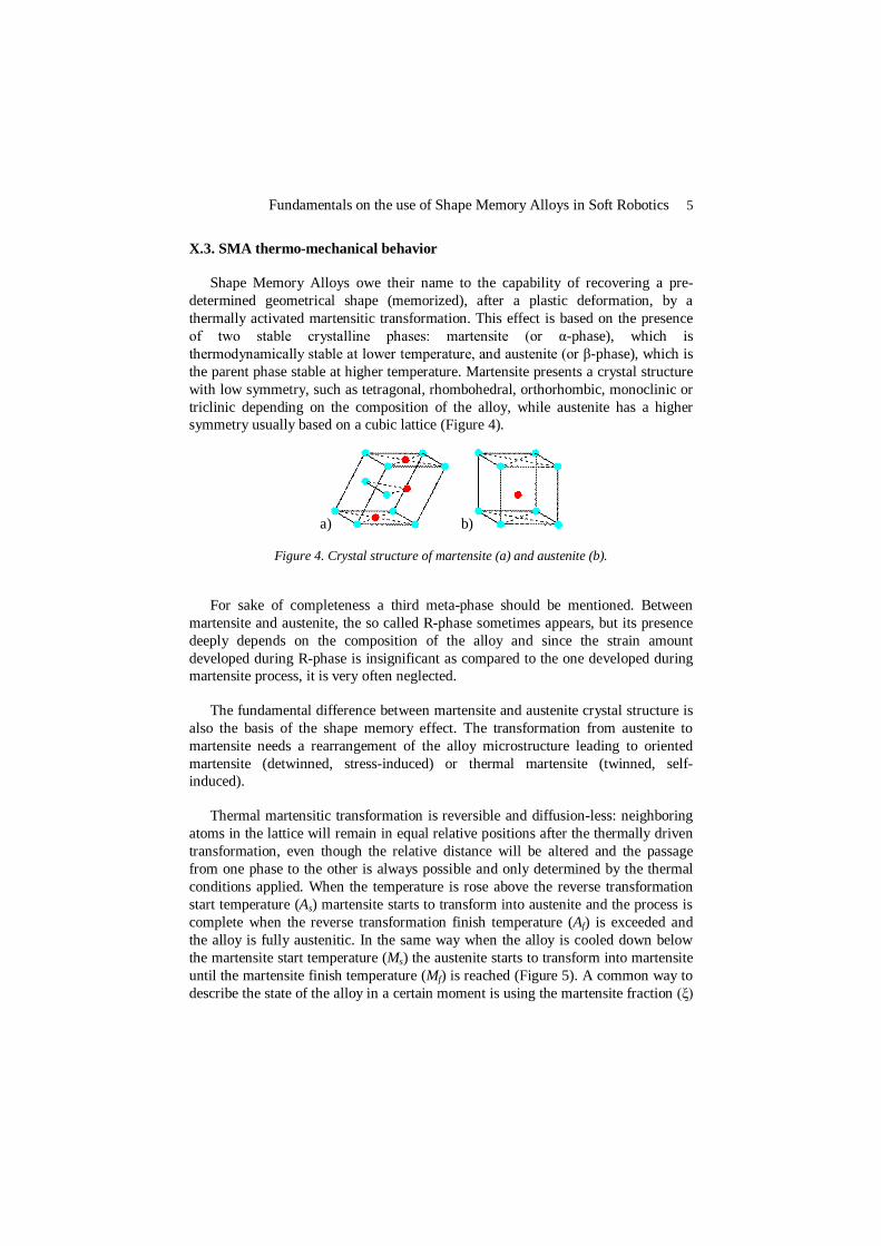
Shape Memory Alloys owe their name to the capability of recovering a pre-determined geometrical shape (memorized), after a plastic deformation, by a thermally activated martensitic transformation. This effect is based on the presence of two stable crystalline phases: martensite (or α-phase), which is thermodynamically stable at lower temperature, and austenite (or β-phase), which is the parent phase stable at higher temperature. Martensite presents a crystal structure with low symmetry, such as tetragonal, rhombohedral, orthorhombic, monoclinic or triclinic depending on the composition of the alloy, while austenite has a higher symmetry usually based on a cubic lattice (Figure 4).
a) b)
Figure 4. Crystal structure of martensite (a) and austenite (b).
For sake of completeness a third meta-phase should be mentioned. Between martensite and austenite, the so called R-phase sometimes appears, but its presence deeply depends on the composition of the alloy and since the strain amount developed during R-phase is insignificant as compared to the one developed during martensite process, it is very often neglected.
The fundamental difference between martensite and austenite crystal structure is also the basis of the shape memory effect. The transformation from austenite to martensite needs a rearrangement of the alloy microstructure leading to oriented martensite (detwinned, stress-induced) or thermal martensite (twinned, self-induced).
Thermal martensitic transformation is reversible and diffusion-less: neighboring atoms in the lattice will remain in equal relative positions after the thermally driven transformation, even though the relative distance will be altered and the passage from one phase to the other is always possible and only determined by the thermal conditions applied. When the temperature is rose above the reverse transformation start temperature (As) martensite starts to transform into austenite and the process is complete when the reverse transformation finish temperature (Af) is exceeded and the alloy is fully austenitic. In the same way when the alloy is cooled down below the martensite start temperature (Ms) the austenite starts to transform into martensite until the martensite finish temperature (Mf) is reached (Figure 5). A common way to describe the state of the alloy in a certain moment is using the martensite fraction (ξ)

6 ISTE Ltd.
that indicates the percentage of structure in martensitic phase. By adding a mechanical load the characteristic transformation temperatures change introducing the stress dependency (stress gradient) depicted in Figure 5.
Figure 5. Diagram showing martensite fraction, ξ, versus temperature, T, relationship at constant loads, σ. Thermodynamic cycles are shifted rightwards (stress gradient) increasing
the transformation temperature values.
Other than changing the characteristic transformation temperature values, if a mechanical load is provided during the thermal martensitic transformation cycle a more complex behavior appears. Temperature, stress and strain are correlated following the relation depicted in Figure 6, that also highlights the shape memory effect of such alloys. In (0) the material is maintained at low temperature in an undeformed and unstressed state presenting a randomly organized twinned martensite. By applying a stress a deformation is induced showing a non-linear response (1) and if the deformation is maintained below 8-10% the only structural change that occurs is a detwinning process that tends to orient the martensite domains. The return to an unstressed condition is associated with a large hysteresis and a residual strain (2) since the reorientation occurred in (1) is caused by an apparent plastic deformation. Increasing the temperature, a thermal cycle is commenced and as already described the alloy undergoes to structural transformation. In (3) the As is reached and martensite starts moving into austenite, while in (4) the process is completed. By continuing increasing the temperature no other effects are obtained (5). This concludes the description of a cycle where the SME is shown. If from this point a load is applied again, a different behavior is shown this time: the higher temperature maintained the alloy in austenitic phase so that the response is much stiffer and linear (6). An higher stress leads to the

Fundamentals on the use of Shape Memory Alloys in Soft Robotics 7
appearance of a plateau that is justified by a stress-induced microstructural change: austenite is transformed into detwinned martensite (7). But since martensite is not stable at high temperatures when the load is removed, the reverse transformation occurs (8) until the alloy is again fully in austenitic phase (9). Point (10) concludes the transformation cycle at high temperature, thus describing the SE effect.
Figure 6. Thermo-mechanical behavior of a SMA showing the dependency among temperature, T, stress, σ, and strain, ε, and the related crystal structures.

8 ISTE Ltd.
X.4. SMA constitutive models
As shown in the previous section, the SMAs exhibit a nonlinear and pseudo-elastic response that varies depending on the temperature and loading conditions. An accurate model of this behavior is a necessary prerequisite for the use of the SMAs as actuators. A mathematical expression in a form that is amenable to incorporation into other engineering tools (finite element procedures or control analysis programs) would enable a fast design of SMA based actuators. Unfortunately due to the complex interdependencies among the variables controlling the SMAs behavior, these materials have been the subjects of numerous constitutive models, without a real supremacy on using a particular one. Several models have been proposed, every one following a different approach. A possible classification proposed by Paiva and Savi [PAI 06] groups in five the most valuable works:
1. Models that take into consideration microscopic (molecular level) or mesoscopic (lattice particles) phenomena;
2. Models based on a macroscopic approach (phenomenological features);
3. Models with assumed phase transformation kinetics;
4. Models based on elastoplasticity theory;
5. Models based on plasticity concepts.
The second group includes the simplest models and they are often used when an in deep description of the microscopic phenomena is not necessary. From an engineering point of view this could be sometimes too much limiting and for these reasons the most popular approach is described by the third group where pre-established simple mathematical functions are used to describe the phase transformation kinetics, thus avoiding a too complex mathematical approach.
Of course also in this case some assumptions are necessary and even in the luckiest eventuality of a level of description that meets all the designer specifications, for the design of a specific actuation system, some thermo-mechanical tests are required anyway. This could appear as a limitation, but from the perspective of a controls engineer, any model that can capture the SMAs response adequately and efficiently (possibly in real time) is a “good” model, irrespective of whether that model has been built on physical principles or purely empirically.

Fundamentals on the use of Shape Memory Alloys in Soft Robotics 9
X.5. Hints on SMA thermo-mechanical testing
Since the testing of SMAs is not yet standardized and unlike conventional alloys, material property tables either are not available or provide incomplete, or even incorrect, information for the user. Commercially available SMAs can present a wide range of possible combination of performances, thus users are often forced to face with testing SMAs in their own laboratory to obtain a satisfactory characterization of the material at hand. Whatever is the model chosen to describe the alloy behavior, in the design phase there are at least three fundamental data whose precision can greatly affect the prediction of the results: the characteristic transformation temperatures (As, Af, Ms, Mf), the Young’s modulus of both austenite and martensite phases and the stress gradient.
Differential Scanning Calorimetry (DSC) is the most precise technique to obtain a complete description of the thermal properties of the alloy. Electrical resistivity scan is a simple alternative method to identify the characteristic transformation temperatures especially if a DSC machine is not available, but results are difficult to interpret and it provides limited data on latent heat and specific heat.
Once DSC thermograms or electrical resistivity scans have been performed to establish the relevant transformation temperatures, in order to assess the remaining data, it is necessary to obtain an overview of the material behavior with respect to axial load-elongation-temperature space (schematically reported in Figure 1 to show the common trend). This is usually observed by performing isothermal and isotonic tests using a tensile machine with a thermally controlled chamber: while imposing a constant temperature, elongation is swept up and down and the load response is measured; while imposing a certain force, temperature is swept up and down and the strain response is measured. One possibility to assess the deformation is measuring the global strain directly from the displacement of the testing machine’s crosshead, but it does not take into account possible local effects due to a non-uniform deformation of the material. Another possibility is to measure local strain (namely only the gage section of the test specimen) through mechanical or optical systems. In both cases special precautions should be considered in gripping the sample to avoid slippage and stress concentration at ends. Moreover to obtain correct results the strain control imposed to the machine should be based on global deformation (not local) and on a deformation rate of about 15105 sL . During these tests a very precise temperature control is also mandatory: Joule effect heating is one of the most used for its simple implementation, but environment conditions and power supplied must be very well controlled; environmental chambers and liquid bath can be useful to cover a broad range of temperature but infrared measures could be disturbed; conduction contact could be exploited using a temperature-controlled heat sink in thermal contact with the specimen.

10 ISTE Ltd.
For reference purpose, typical values which describe thermo-mechanical (but also chemical and magnetic) properties of a NiTi alloy are reported in Table 1.
Table 1. Typical values for a NiTi alloy.
Melting point 1310°C Density 6450 kg/m3 Thermal conductivity, austenite (martensite) 18 (8.6) W/m°C Thermal hysteresis 15-30°C Specific heat 470-720 J/kg°C Transformation enthalpy 3.2-12 kJ/kg Transformation temperatures (unstressed), As
Af
Ms Mf
75°C 88°C 68°C 60°C
Stress gradient 0.12 °C/MPa Electrical resistivity, austenite (martensite) 100 (80) µΩcm Magnetic permittivity 1.002 Maximum deformation (OWE) 8% Maximum deformation (TWE) 2% Young’s modulus, austenite (martensite) 83 (28-41) GPa Yield stress, austenite (martensite) 200-800 (150-300) MPa Breaking load (cold worked) 1500 MPa Fatigue limit (106 cycles) 350 MPa Corrosion resistance Excellent
X.6. Design principles
Once the thermo-mechanical behavior of the alloy has been assessed, the design of the actuation system cannot continue without considering its embodiment. While until now the introduced concepts have a general connotation and can be applied in any application, for the reminder of the chapter in several cases the considerations have a narrower applicability focusing on SMA based actuation systems for Soft Robotics.
When the design phase of the actuation system begins, there are some important aspects that should be taken into consideration for a correct set-up of the device.

Fundamentals on the use of Shape Memory Alloys in Soft Robotics 11
X.6.1. Geometrical choice
The most important factor in the design phase is represented by the definition of the geometrical parameters of the alloy to be used. As already mentioned, SMAs show very unique mechanical performances in terms of power density, but very limited deformation capability. Thus, while theoretically SMA wires could be used as the simplest linear actuators ever seen, its use in straight configuration is suitable for a very limited number of applications. In order to meet specific requirements, SMAs are more often used as active material to be shaped in the right configuration going to a trade-off between available force and deformation capability.
SMAs are commercially available in different forms: wires with different diameter and cross-sections, ribbons with different geometrical proportions, thin films and plates for sputtering deposition. The most important driving factor on the choice of the right design of the actuation system is represented by the description of the tensional state of the material during its working cycles. Generally speaking a material can be subjected to two kind of stresses: normal and shear stress whose combination determines three different deformation states: tensile, bending and torsion. Each of these deformations can be exploited as strained initial configuration for the alloy, but they present different efficiency depending on the average stress imposed across the section. In the optimal case all the material is subjected to the same stress so if the maximum allowed stress is not exceeded, all the recoverable deformation is uniformly used. Any tensional state different from this will exploit only partially the capability of the alloy.
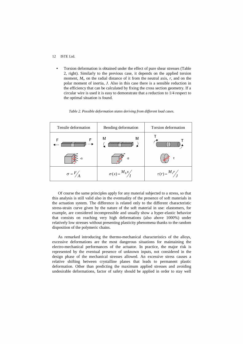
• Tensile deformation is obtained when an axial load is applied to a body, (e.g. a bar subjected to pure tension or compression) so that the force passes through its centre (Table 2, left). In this case the stress, σ, can be obtained by dividing the total normal force, F, by the bar's cross-sectional area, A. In this case the tensional state of the body is homogeneous since all the material experiences the same stress level so representing the optimal way to exploit all the potentiality of the material.
• Bending deformation generates compressive and tensile stresses at any cross section that vary linearly (Table 2, centre). They depend on the applied bending moment, Mb, on the distance of it from the neutral plane, x, and on the moment of inertia, I. In this case the maximum strain will occur in the upper and lower part of the material, while all the intermediate states will present partial deformations that translate in a lower produced force. For example if a rectangular cross section is considered, given the same maximum allowed stress, the efficiency in using the recoverable capability under bending deformation is reduced to the half respect to a tensile deformation.
12 ISTE Ltd.
• Torsion deformation is obtained under the effect of pure shear stresses (Table 2, right). Similarly to the previous case, it depends on the applied torsion moment, Mt, on the radial distance of it from the neutral axis, r, and on the polar moment of inertia, J. Also in this case there is a sensible reduction in the efficiency that can be calculated by fixing the cross section geometry. If a circular wire is used it is easy to demonstrate that a reduction to 1/4 respect to the optimal situation is found.
Table 2. Possible deformation states deriving from different load cases.
Tensile deformation Bending deformation Torsion deformation
AF I
xMx b)( JrMr t)(
Of course the same principles apply for any material subjected to a stress, so that this analysis is still valid also in the eventuality of the presence of soft materials in the actuation system. The difference is related only to the different characteristic stress-strain curve given by the nature of the soft material in use: elastomers, for example, are considered incompressible and usually show a hyper-elastic behavior that consists on reaching very high deformations (also above 1000%) under relatively low stresses without presenting plasticity phenomena thanks to the random disposition of the polymeric chains.
As remarked introducing the thermo-mechanical characteristics of the alloys, excessive deformations are the most dangerous situations for maintaining the electro-mechanical performances of the actuator. In practice, the major risk is represented by the eventual presence of unknown inputs, not considered in the design phase of the mechanical stresses allowed. An excessive stress causes a relative shifting between crystalline planes that leads to permanent plastic deformation. Other than predicting the maximum applied stresses and avoiding undesirable deformations, factor of safety should be applied in order to stay well
Fundamentals on the use of Shape Memory Alloys in Soft Robotics 13
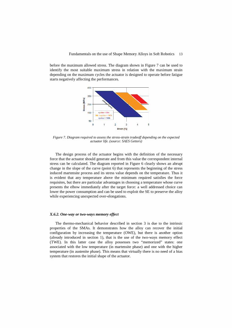
before the maximum allowed stress. The diagram shown in Figure 7 can be used to identify the most suitable maximum stress in relation with the maximum strain depending on the maximum cycles the actuator is designed to operate before fatigue starts negatively affecting the performances.
Figure 7. Diagram required to assess the stress-strain tradeoff depending on the expected actuator life. (source: SAES Getters)
The design process of the actuator begins with the definition of the necessary force that the actuator should generate and from this value the correspondent internal stress can be calculated. The diagram reported in Figure 6 clearly shows an abrupt change in the slope of the curve (point 6) that represents the beginning of the stress induced martensite process and its stress value depends on the temperature. Thus it is evident that any temperature above the minimum required satisfies the force requisites, but there are particular advantages in choosing a temperature whose curve presents the elbow immediately after the target force: a well addressed choice can lower the power consumption and can be used to exploit the SE to preserve the alloy while experiencing unexpected over-elongations.
X.6.2. One-way or two-ways memory effect
The thermo-mechanical behavior described in section 3 is due to the intrinsic properties of the SMAs. It demonstrates how the alloy can recover the initial configuration by increasing the temperature (OWE), but there is another option (already introduced in section 1), that is the use of the two-ways memory effect (TWE). In this latter case the alloy possesses two “memorized” states: one associated with the low temperature (in martensite phase) and one with the higher temperature (in austenite phase). This means that virtually there is no need of a bias system that restores the initial shape of the actuator.
14 ISTE Ltd.
At first one can think that the use of the TWE is much better than the OWE, but there is a series of drawbacks that should be considered:
• The TWE is an acquired property, meaning that a complex thermo-mechanical process is necessary including several shape memory cycles followed by superelastic cycles (more details can be found in [DUE 90]);
• The recoverable strain that the alloy is able to resist before “losing its memory” is much more limited: it rarely exceeds 2% that in turn limits the produced force too.
Thus the choice between OWE or TWE widely depends on the specific application, but also on the possibility to add a restoring system with the aim to provide (or at least support) the necessary force to return to the initial strain.
X.6.3. Restoring force
Connected to the previous paragraph, if an external restoring force is preferable, there exist three different ways of implementation:
1. Constant force. This is the simplest case where a suspended mass or a linear spring is connected to one end of the alloy and its force is used to restore the actuator in the deformed configuration in order to allow starting a new working cycle. From a design viewpoint, it is important to notice that in this case there is no shift in the activation temperature values since the applied load is always constant.
2. Variable passive force. Another alternative solution is represented by the use of a bias spring which provides a force linearly dependent on its deformation. Even if a few additional design efforts are necessary this is the most used solution.
3. Variable active force. The most refined method to provide an antagonistic restoring force is to place a second SMA that acts counterbalancing the effect of the first one. The alternate activation of the two actuators allows the completion of the working cycles and virtually they could be also used to finely control the position of their connecting point by balancing the two generated forces.
The last two options cover quite all the applications of SMAs in Robotics and the same trend is proofed also in the narrower field of Soft Robotics especially the second solution listed above. Typically soft robots present a compliant and flexible body that already stores the elastic deformation energy produced by the actuators (whatever they are), thus providing a restoring force that can be used to return to the strained configuration. This represents the best integration of an actuation system in

Fundamentals on the use of Shape Memory Alloys in Soft Robotics 15
which synergistically works with the robot body. On the other hand this possibility can be pursued only if body material parameters can be adjusted without constraints. In this sense the choice is not nearly trivial, since typically elastic properties of the body have to meet also other specifications and a tradeoff is necessary. Moreover the mechanical response of the elastomers is anything but linear, thus the mechanical coupling between the elastomer and the SMA response has to be taken into consideration. Fortunately, often tensile-compression tests (carried out setting similar working condition especially for the deformation range) are sufficient to derive the data to describe the behavior of the coupled system (Figure 8).
Figure 8. Stress vs. strain relationship of a SMA in martensite (blue) and austenite (red) phase that acts against an elastomer (green). The intersection points among the curves dictate
the maximum available stroke that the system can implement.
X.6.4. Anchor points
Another important point to be taken into consideration is a practical aspect. SMA actuators are often used as wires (straight or whatever shape) meaning that they need anchor points where the ends have to be fixed. These points have to guarantee mechanical stability and avoid a too local point of force application that (after several cycles) could lead to a shift of the terminals or to the total failure of the actuator. Moreover these points are often used as the most suitable place where electronic connections are lodged. In the simplest case (if the application allows it), the alloys can be mechanically fixed on a rigid plate (crimped in hollow cylinders or with bolts) that can be embedded as floating parts in an elastomeric matrix and providing a perfect electric connection site. Where the use of rigid plates is not allowed a more complex solution has to be used. But this issue rises an important question. In Soft Robotics hard materials should not be used, but “hard” is a relative concept. What is the boundary between hard and soft? And consequently: how can the right properties of the needed components should be addressed? In Soft Robotics usually there is a huge use of elastomeric materials and the choice of the most suitable one is dictated by the overall passive properties that the robot is designed to

16 ISTE Ltd.
present. Thus one tentative answer to the previous question is: the boundary between hard and soft is traced by the overall passive properties of the robot so every embedded component or sum of components that dramatically change this passive behavior has to be considered too hard and consequently should be discarded.
Possible connection sites can be easily introduced by using braided fibers (commonly used also to couple tendon driven actuation systems and soft materials) available in different forms and materials. Woven or knitted textiles and braided sheaths can be professionally manufactured in order to meet specific dimensions and shapes and they can be easily embedded in a soft matrix. Of course this inclusion affects the elastic properties of the soft material, so that it should be considered in the body global passive response and once again showing the importance of a design approach that takes into account all the components of the system from the very early phases.
X.7. Fabrication methods
When the actuator specifications can be met using a straight geometry wires or ribbons of the desired dimension and cross-section can be easily found off-the-shelf, but in most cases more complex geometries are necessary. There are several methods to obtain particular shapes, here four of the most common will be shown.
Manual fabrication of the SMA actuators can represent a fundamental early step in the design process to realize a large number of prototypes in a relatively fast way at low cost, before using more advanced technologies. Therefore a good fabrication method would be preferable to obtain repeatability, since small differences and imprecision can greatly affect the mechanical performance of the actuators. The manual method starts from row material like wires or ribbons that will be shaped in the final configuration through a heat treatment. To memorize the desired shape, the spring has to be mechanically constrained and maintained at 450°C for 30 minutes inside a furnace under flowing nitrogen or other inert gases (to prevent oxidation). After this time has elapsed, the alloy is water quenched.
Laser machining provides a design flexibility that is unmatched by other techniques. It allows the designer to simply alter a computer drawing in order to modify the final product and the feature sizes can be maintained on the order of 25 μm. This technique can occasionally cause heat damage, which manifests as a heat-affected zone (HAZ) at the cut edges, and can affect the performances of the actuators. In this case postprocessing such as electropolishing on these actuators could be used to eliminate the HAZ and to smooth the surface characteristics.
Fundamentals on the use of Shape Memory Alloys in Soft Robotics 17
Sputter deposition of NiTi films is a valid alternative to the use of foils [WOL 95] and it can be utilized for fabricating and patterning at the same time. With this method also very thin layers (normally less than 10 μm in thickness) can be deposited on silicon, glass or polymeric substrates providing the first step of eventual other fabrication steps.
Wet-chemical etch process has been also successfully tested and involving the use of soft lithography it adds the possibility to obtain a batch process where SMA foils are processed in compound with SU-8 [LEE 08]. It allows a precise fabrication of very small planar actuators and its contemporary embedding in a fixing component.
One last topic regarding the fabrication method is about joining SMA. Once the stable mechanical fixing is provided, the alloy has to be electrically connected to allow the current flow and its activation. In the case of a mechanical anchor point, the wire terminals can be simply crimped together with the alloy. Although the mechanical solution is considered the simplest and most reliable, there are other more elegant solutions to join SMA for electrical connection [MIN 01]: welding a SMA to itself is possible with CO2 laser, Nd:YAG laser, tungsten inert gas (TIG) and resistance welding without affecting the shape memory effect of the alloys; soldering is possible using halogen-based fluxes or mild fluxes if the surface is plated with Ni or noble metals; joining SMAs with other dissimilar metal is more challenging and needs the use of proper interlayer materials.
X.8. Activation methods and control design
The shape of an SMA is based on thermal control, but there exist at least two ways of causing a temperature increase: direct heat flow and Joule effect. While the first is usually used only in very particular cases where the alloys are used to monitor the temperature of an environment (fire alarms) or to control it in order to maintain always the same temperature (water valves), the second one is the most used for an active control of the alloy state and can be electrically or inductively driven. A SMA actuator can be thought as a variable resistance due to geometrical and structural modifications. The main problem in controlling SMAs is the wide hysteresis shown during their thermal cycles (as already shown in Figure 5).
Another fundamental point to bear always in mind: systems based on thermal effect are deeply affected by the environmental conditions and neglecting thermal properties of surrounding materials could turn into performances worsening. Thus in the case of soft robots where the SMA actuators are embedded in a liquid or

18 ISTE Ltd.
solid/elastomeric means, part of the design of the control system is actually strongly connected to the choice of the right materials to be used for the robot itself.
Depending on the desired application different activation methods can be used and the choice of the control types also depends on the geometrical properties of the actuation system and on the complexity of the environment. The general equation which describes the power transformation and the relation among the variables that play a role in the thermal process is here reported:
))(()( 2aTtThAtRi
dtdHV
dttdTcV
[x.1]
The first two terms represent respectively the power used through Joule heating to raise the actuator temperature, where (except for the more obvious meaning of the symbols used) ρ is the density of the material, c the specific heat, V the volume, H the latent heat for the transformation, ξ the martensite fraction in the alloy at a given time; the third term is the electrical power delivered to the actuator; the fourth quantifies the heat dissipated on the environment where h is the convective heat transfer coefficient and Ta is the room temperature.
The velocity of the heating process depends on the supplied electrical power, but the limiting factor on the working frequency is represented by the cooling phase. Looking at eq. x.1 it is clear that the velocity of this phase can be increased in two different ways: increasing h by using the right geometrical conditions (see section below) or maximizing the external area, A, which exchanges heat with the environment. Forced convection and Peltier effect can be used in this sense. When SMAs in straight wires or springs are used there is another common possibility to affect the heating-cooling cycles: to fit a sheath around the alloy. Of course its mechanical contribution has to be negligible (or at least considered in the force balance), but also from the thermal point of view the critical radius notion has to be taken into consideration: basically if a thermally non conductive material is placed around the alloy, this additional insulation increases the conduction of the insulation layer, but contemporary decreases the convection resistance of the surface. It means that there is a radius that maximizes the heat flux and every bigger or smaller radius obstacles heat dispersion.
This is a general principle, but finds a special importance in Soft Robotics since sometimes the SMA actuators are directly embedded inside an elastomeric body thus heavily conditioning the thermal cycles. Polymers are usually thermal insulators and elastomers are not an exception. Of course in the thermal conductivities list it behaves better than air, but it obstacles heat dispersion respect to other materials like water or metals. In this case liquid fillers could be used to
Fundamentals on the use of Shape Memory Alloys in Soft Robotics 19
speed up the cooling phase, but particular attention is needed to avoid eventual appearance of chemical reactions electrically induced.
X.8.1. On-off activation in open-loop control
The simplest case one can imagine for an application of a SMA actuator has very well known conditions both for the thermal and mechanical properties of the system and for the external environment that will affect the actuator cycles. In this kind of application there is no modulation of the produced force, it only guarantees the repeatability of the same performances every time the actuator is activated (on-off activation). In this case the dynamic transient of the heating process is not known, but for an on-off activation this is not necessary. This means that once fixed the mechanical parameter of the actuator (in order to meet the application), eq. x.1 reduces to the third and fourth terms and it can be used to derive the right electrical power needed to obtain the full activation of the material. This kind of approach implicates:
1. Numerically, the resistance of the alloy has to be set to the austenite phase value. This approximation leads to an underestimation of the initial resistance value, but it self-adjust while heating up.
2. The driving system should be able to supply the same power whatever is electrical load (in order to fix the value of the third term of eq. x.1), since the applied voltage and the drawn current have to be maintained insensible respect to resistance variations.
3. The geometry has to be simple enough to allow an acceptable description of the cooling term through the expression of the parameter h which is often an experimental approximation. In [WEL 08] a wide collection of examples can be found for laminar and turbulent flows for forced convection as well as natural convection for several geometries.
If the geometry of the system presents a higher complexity, the thermal conditions evolution could be hard to predict. The known models to describe the heat exchange have been derived for simple geometries, but shifting towards more advanced shaping, like helicoids or planar springs, they lose their accuracy. Moreover when more independent actuators work in a limited space, a combined thermal action has to be considered: the activation of one actuator influences the environment that in turn can affect the performances of the nearby actuators’ thermal cycles. In this case the most effective solution is represented by the use of Finite Element Analysis programs, where once virtually reconstructed the geometry of the system and set all the thermal and electrical properties, a multi-physics

20 ISTE Ltd.
analysis can aid the evaluation of the optimal working conditions as well as the most critical points and it allows the formalization of the fourth term of eq. x.1.
X.8.2. Modulated activation in closed-loop control
The proportional control of SMAs based on mathematical models have often not sufficient accuracy and for this reason feed-back control is very usually utilized. This method is the most complex, but the most precise even if it requires a more sophisticated design. In this case the uncertainty of the environment and the complexity of the system can be increased as required since the state of the alloy is continuously monitored by sensors. There are two available ways to close the loop: external variables feedback or internal state variable feedback. The first family is based on the measurement of displacement (by using strain gages, mechanical extensometers or optical sensors in parallel configuration respect to the actuator stroke direction) or force (with load cells). Unfortunately the knowledge of these two variables is often not enough to assess the real state of the alloy since they cannot reveal temperature disturbances or external loads and as a result they are likely to cause overheating. On contrary, monitoring the internal state of the alloy is more effective and it consists on measuring temperature and/or electrical resistance. Several methods of measuring the temperature could be applied like thermocouples or noncontacting infrared temperature probes, but they present very limited usability for micro-scale applications. Nowadays the electrical resistance measure remains the most used and effective feed-back to control SMA based actuators. In fact, the measure of inner electrical resistance allows to detect the alloy martensite fraction. The method consists in measuring the electrical resistance of an SMA element, calculating a maximum safe heating current as a function of measured resistance, and ensuring that the actual heating current does not exceed this maximum value. The implementation of this control is based on a linearized model which correlate the strain versus the electrical resistance of the alloy that usually presents a fairy small hysteresis (Figure 9).
Figure 9. Resistance vs. strain curve. Due to the low hysteresis the linearized function can be used in the control loop.

Fundamentals on the use of Shape Memory Alloys in Soft Robotics 21
The only limit of this method is due to the sensitivity of the alloy to external loads. Antagonistic forces applied on the actuators introduce a new variable which make the relation non univocal: one cannot know if the resistance change is due to an external stress which stretches the alloy or to a temperature change in the environment. In this case the stress has to be measured together with the resistance, so that the right strain-resistance curve can be selected.
In the implementation of a closed-loop control besides a few attempts with elaborated strategies using complex hysteretic models to compensate for the material behavior [HAS 98] or neural networks and sliding-mode robust controllers for precision tracking of SMA [SON 03], the most cited and described in literature are based on Proportional, Integral and Derivative (PID) control even if they have been found to produce steady-state errors as well as overshooting and undershooting in heating and cooling phase respectively. Both continuous control and modulation techniques are widely used, but pulsed driving methods have been proved to present more advantages: Pulse Width Modulated - PD controller, Pulse Width Pulse Frequency Modulation - PD controller and the continuous PD controller have been compared under the same conditions demonstrating that at the cost of a reduced response time the performance of the PW modulator is comparable to that of a continuous controller in terms of control accuracy, but offers dramatic energy saving and improves the system robustness to external disturbances [MA 03].
X.9. Applications in Soft Robotics
Soft Robotics is a newly born field that is now starting showing first convincing results. In this framework the coupling of soft and/or flexible materials with SMA actuators has been successfully implemented especially in biomimetic and bioinspired Robotics. Caterpillars, worms and octopus arms, are the most cited and studied. Reproducing the capabilities of such animals requires, in fact, the presence of a soft body with active abilities of motion without the use of rigid structures.
Among several caterpillar-like robot, one of the most effective examples is represented by the GoQBot [LIN 11]. It replicates a very fast self-propelled wheeling behavior producing a ballistic rolling by changing its body configuration in 250 ms. The soft robot is composed of three functional components: a soft silicone body molded in a straight and long geometry (bar-like), two independent SMA actuators fixed in parallel respect to the body allowing its anterior and posterior flexion and a pair of tail skids providing stability. The control system is based on a Pulse Width Modulation (PWM) driving with high power stimulations in order to achieve a very impulsive response.

22 ISTE Ltd.
Earthworms inspired peristaltic locomotion platforms and contracting robots that exploit antagonistic arrangement and elastic properties of the soft materials they are made of. In [SEO 10] a flexible braided mesh-tube structure is used as a support for SMA springs arranged in antagonistic manner: circularly to squeeze and elongate the structure and longitudinally to shorten it. Sequential activation of the spring groups leads to peristaltic motion that can be used as a locomotion system. 400 mA current with short pulse time is experimentally found to be the most effective way to activate the springs and the coordination of the segments is obtained by a purposely developed gait controller. Closed loop control is implemented with the measure of the radius changes by means of Hall effect sensors. In [KIM06] a different embodiment demonstrates another approach to generate a forward locomotion: a TWE SMA spring located inside a cylindrical silicone bellow. The activation of the spring lets the structure shorten and the bellow delivers the bias force necessary to support the return phase of the alloy. The control system is open-loop and the right timing for cooling and heating has been experimentally set. The robot is completely autonomous and embeds battery for activation and wireless communication for on/off signals.
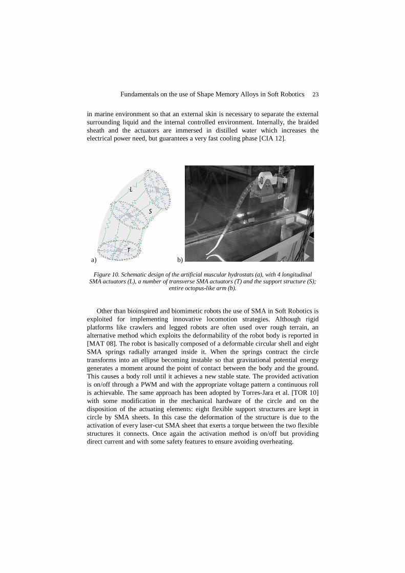
Another example of SMAs successfully used as actuation technology for Soft Robotics is represented by the development of an artificial octopus-like arm. The aim of the work was to develop an octopus-like arm with similar motion capabilities respect to the natural counterpart by reproducing the fundamental characteristics that make it move so dexterously. The key factor which determines the performance of the octopus arm is the “muscular hydrostat”, a peculiar structure with muscles arranged on longitudinal and transverse planes, which can deform and vary its stiffness with contractions (in [LAS 12] an exhaustive and complete explanation is reported). Appling the principles of the muscular hydrostat led to the design of an artificial muscular hydrostat that is based on a conical braided sheath that is used as the body of the arm and as a support for the SMA based actuation system (Figure 10).
Helicoidal springs have been chosen to meet the requirements of force and deformation. The transverse and longitudinal actuators act as antagonistic elements since the former is able to squeeze the braided sheath causing an elongation of the structure (and consequently of the longitudinal actuators too) while the latter is able to shorten the arm and to increase the diameter (restoring the transverse actuators). By manufacturing a long structure that counts on several sections like those depicted in Figure 10a an entire octopus-like arm can be reproduced (Figure 10b). The combination of the action of the transverse and longitudinal actuators allows the reproduction of the octopus basic movements like elongation, shortening, bending in any direction (by activating asymmetrically the longitudinal springs) and stiffening (by contracting simultaneously both kind of actuators). An on/off activation is provided using PWM in an open-loop control. The robot has been designed to work
Fundamentals on the use of Shape Memory Alloys in Soft Robotics 23
in marine environment so that an external skin is necessary to separate the external surrounding liquid and the internal controlled environment. Internally, the braided sheath and the actuators are immersed in distilled water which increases the electrical power need, but guarantees a very fast cooling phase [CIA 12].
a) b)
Figure 10. Schematic design of the artificial muscular hydrostats (a), with 4 longitudinal SMA actuators (L), a number of transverse SMA actuators (T) and the support structure (S);
entire octopus-like arm (b).
Other than bioinspired and biomimetic robots the use of SMA in Soft Robotics is exploited for implementing innovative locomotion strategies. Although rigid platforms like crawlers and legged robots are often used over rough terrain, an alternative method which exploits the deformability of the robot body is reported in [MAT 08]. The robot is basically composed of a deformable circular shell and eight SMA springs radially arranged inside it. When the springs contract the circle transforms into an ellipse becoming instable so that gravitational potential energy generates a moment around the point of contact between the body and the ground. This causes a body roll until it achieves a new stable state. The provided activation is on/off through a PWM and with the appropriate voltage pattern a continuous roll is achievable. The same approach has been adopted by Torres-Jara et al. [TOR 10] with some modification in the mechanical hardware of the circle and on the disposition of the actuating elements: eight flexible support structures are kept in circle by SMA sheets. In this case the deformation of the structure is due to the activation of every laser-cut SMA sheet that exerts a torque between the two flexible structures it connects. Once again the activation method is on/off but providing direct current and with some safety features to ensure avoiding overheating.

24 ISTE Ltd.
One last example is represented by a very recent and original work where SMA are used in a robotic origami: these kind of robots are able to fold into 3D shapes starting from a nominally 2D sheet. In [PAI 11] a stretchable circuitry based on liquid-metal-filled channels in an elastomer substrate is integrated with a tiled origami module actuated by a SMA actuator. In this case the activation of the alloys is not directly achieved by Joule effect but with the use of external heaters to avoid power losses in the circuitry path.
X.10. Conclusions
Shape Memory Alloys are a relatively new class of smart materials which demonstrated its capability of being successfully used in alternative to traditional actuation methodologies. Examples of applications in Robotics can be found in the biomedical field ranging from active endoscopes and catheters including advanced operational instrumentation to implantable drug delivery devices where a high degree of miniaturization is mandatory and also in the humanoid robots field where the functional similarity with natural muscles allows the substitution of traditional motors with locally embedded SMA actuators in replicating anthropomorphic limbs. Other commercial applications can be found: in air conditioners to automatically control the air flux temperature without using thermostats and motors; in the regulation of air flow in electronic oven; in automatic dry boxes where solenoids used to activate the mechanism that allows the desiccant material to be regenerated can be replaced with a SMA spring; in cooling systems for automobiles, where SMAs driven valves allow the cooling water passing into the radiator only if the engine is warm.
These examples show that at present SMA technology can be used at industry level only in very precise and limited applications (thermal activation) and this is mainly due to the already mentioned control issues that often do not allow an optimal exploitation of the material properties. But the still growing number of publications on the field (both from a material science and engineering point of view) demonstrates a high interest in the possibility of substituting traditional actuation technologies with SMAs especially in the applications where space and weight are the main constraints. In this sense Soft Robotics is a paradigmatic example: in a research area which grounds on the necessity of achieving adaptive, flexible interaction also with unexpected environment and intrinsically safe, SMAs are particularly appreciated as demonstrated by the reported application examples. Alternative solutions are represented by cable driven system and fluidic actuators, but their usability is limited by the necessity of bulky external components necessary to drive the systems like electromagnetic motors and fluidic pumps respectively. Other more innovative solutions are under evaluation and they seem to be very
Fundamentals on the use of Shape Memory Alloys in Soft Robotics 25
promising: Electro Active Polymers and Shape Memory Polymers are the most representative examples, but the maturity of such technologies does not allow a wide applicability yet. Thus at present SMAs represent one of the most effective soft/flexible actuator technology available. On the other side Soft Robotics is a very new born research area thus its potential has not been totally exploited yet. But ongoing progresses anticipate a future trend where robotic systems will be complemented by soft technologies. Inherent mechanical properties of the soft structure will allow more resilient performances and adaptive behaviors reducing electrical and algorithmic complexity. From this point of view the combination of soft/flexible materials and SMAs could give a very important contribution in the development of robotic systems following a Mechatronics approach as these Soft Robotics technologies will be crucial component in future robotic applications.
X.11. Bibliography/References
[ALB 08] ALBU-SCHAFFER A., EIBERGER O., GREBENSTEIN M., HADDADIN S., OTT C., WIMBOCK T., WOLF S., HIRZINGER G., “Soft robotics,” IEEE Robotics and Automation Magazine, vol. 15, 2008, p. 20-30.
[CIA 12] CIANCHETTI M., FOLLADOR M., MAZZOLAI B., DARIO P., LASCHI C. “Design and development of a soft robotic octopus arm exploiting embodied intelligence” ICRA’12, St. Paul, Minnesota, May 14-18 2012, USA, p. 5271-5276.
[DUE 90] DUERING T.W., MELTON K.N., STÖCKEL D., WAYMAN C.M. Engineering Aspects of Shape Memory Alloys, Butterworth-Heinemann, London, 1990.
[HAB 07] HABIB M. K., “Mechatronics: A Unifying Interdisciplinary and Intelligent Engineering Paradigm”, IEEE Industrial Electronics Magazine, Vol. 1, Issue 2, Summer 2007, p. 12-24.
[HAS 98] HASEGAWA T., MAJIMA S. “A control system to compensate the hysteresis by Preisach model of SMA actuator”, 9th International Symposium on Micromechatronics and Human Science, 1998, p. 171–176.
[KIM 06] BYUNGKYU K., MOON G. L., YOUNG P. L., YONGIN K., GEUNHO L. “An earthworm-like micro robot using shape memory alloy actuator”, Sensors and Actuators A, 125, 2006, p. 429-437.
[LAS 12] LASCHI C., MAZZOLAI B., CIANCHETTI M., MARGHERI L., FOLLADOR M., DARIO P. “A Soft Robot Arm Inspired by the Octopus”, Advanced Robotics (Special Issue on Soft Robotics), 26 (7), 2012, p. 709-727.
[LEE 08] LEESTER-SCHÄDEL, M., HOXHOLD, B., LESCHE, S., DEMMING, S. BÜTTGENBACH, S., “Micro actuators on the basis of thin SMA foils,” Microsystem Technologies, Vol. 14, No. 4, 2008, pp. 697-674.

26 ISTE Ltd.
[LIN 11] LIN H.T., LEISK G.G., TRIMMER B., “GoQBot: a caterpillar-inspired soft-bodied rolling robot” Bioinspiration and Biomimetics, vol. 6, 2011, 026007.
[MA 03] MA N., SONG G., “Control of shape memory alloy actuator using pulse width modulation” Smart Materials and Structures vol. 12, 2003, pp. 712-719.
[MAT 08] MATSUMOTO Y., NAKANISHI H., HIRAI S. “Rolling locomotion of a deformable soft robot with built-in power source” CLAWAR’08, Coimbra, September 8-10, 2008, Portugal, p. 365–372.
[MIN 01] WU M.H. “Fabrication of Nitinol Materials and Components” SMST’01, Kunming, 2001, China, p. 285-292.
[PAI 06] PAIVA A., SAVI M.A. “An overview of constitutive models for shape memory alloys” Mathematical Problems in Engineering, 2006, p. 1-30.
[PAI 11] PAIK J. K., KRAMER R. K., WOOD R. J., “Stretchable circuits and sensors for robotic origami”, IROS’11, San Francisco, California, September 25-30 2011, USA, p. 414-420.
[SEO 10] SEOK S., ONAL C.D., WOOD R., RUS D., KIM S., “Peristaltic Locomotion with Antagonistic Actuators in Soft Robotics” ICRA’10, Anchorage, May 3-8 2010, Alaska, p. 1228-1233.
[SON 03] SONG G., CHAUDHRY V., BATUR C. “Precision tracking control of shape memory alloy actuators using neural networks and sliding-mode based robust controller”, Smart Materials and Structures, vol. 12, 2003, p. 223–231.
[TOR 10] TORRES-JARA E., GILPIN K., KARGES J., WOOD R. J., RUS D. “Compliant Modular Shape Memory Alloy Actuators” IEEE Robotics and Automation Magazine. Vol. 17, Issue 4, 2010, p. 78-87.
[TRI 08] TRIVEDI D., RAHN C., KIER W., WALKER I., “Soft robotics: biological inspiration, state of the art, and future research,” Applied Bionics and Biomechanics, vol. 5, 2008, p. 99-117.
[WEL 08] WELTY J.R., WICKS C.E., WILSON R.E., RORRER G.L., Fundamentals of Momentum, Heat and Mass Transfer, 5th Edition. John Wiley & Sons Ltd, 2008.
[WOL 95] WOLF R.H., HEUER A.H., “TiNi (Shape Memory) Films on Silicon for MEMS applications” Journal of Microelectromechanical Systems, vol. 4, no. 4, 1995, p. 206-212.


![Fatigue Crack Growth Fundamentals in Shape Memory Alloys · 2017. 8. 26. · crack initiation in shape memory alloys [10–16] describing the role of slip, the origin of irreversibilities,](https://static.fdocuments.in/doc/165x107/60f6a6c2b0a4b430bc037d34/fatigue-crack-growth-fundamentals-in-shape-memory-alloys-2017-8-26-crack-initiation.jpg)