Fundamentals of Electric Circuits Chapter 12 Copyright © The McGraw-Hill Companies, Inc. Permission...
30
Fundamentals of Electric Circuits Chapter 12 Copyright © The McGraw-Hill Companies, Inc. Permission required for reproduction or display.
-
Upload
bennett-carter -
Category
Documents
-
view
215 -
download
0
Transcript of Fundamentals of Electric Circuits Chapter 12 Copyright © The McGraw-Hill Companies, Inc. Permission...

Fundamentals of Electric CircuitsChapter 12
Copyright © The McGraw-Hill Companies, Inc. Permission required for reproduction or display.

Overview
• This chapter will introduce the concept of three phase AC power.
• The two configurations for sources and loads for three phase circuitry will be discussed.
• The different schemes for connecting these two configurations will be covered.
2

Single Phase vs. Polyphase
• Households have single phase mains power supplied.
• This typically in a three wire form, where two 120V sources with the same phase are connected in series.
• This allows for appliances to use either 120 or 240V
3

Polyphase
• Circuits that operate at the same frequency but with multiple sources at different phases are called polyphase.
• Generating multiple phases is relatively simple when using a generator. Placing coils at positions such that a lag in the current is produced leads to a phase lag.
• In power grids, three phase power is used for a variety of reasons.
4

Three Phase Power
• It is easy to extract single or two phase power from a three phase system, satisfying the cases where this is needed.
• The instantaneous power in a three phase system does not pulsate like it does in a single phase system.
• Lastly, the transmission of three phase is more economical than transmitting the equivalent single phase power.
5

Balanced Three Phase
• Three phase voltages are typically produced by a three phase AC generator.
• The output voltages look like below.
6

Connecting the Sources• Three phase voltage sources can be
connected the loads by either three or four wire configurations.
• The three wire configuration is accomplished by a Delta connected source.
• The four wire system is accomplished using a Y connected source.
7

Balanced Source
• A wye connected source is said to be balanced when the sum of the three voltages is zero:
• This can only happen if:
• There are two sequences for the phases:
8
Negative sequencePositive sequence
0an bn cnV V V
an bn cnV V V
0
120
240 120
an p
bn p
cn p p
V V
V V
V V V
0
120
240 120
an p
cn p
bn p p
V V
V V
V V V

Phase Sequence
• The phase sequence is determined by the order in which the phasors pass through a fixed point in the phase diagram.
• The phase sequence is important as it determines the direction of rotation of a motor connected to the power source.
• Likewise, the phase sequence of the generator is determined by the direction in which it is turned.
9

Balanced Loads
• Similar to the source, a balanced load is one that has the same impedance presented to all three voltage sources.
• They may also be connected in either a Delta or wye configuration.
• For a balanced wye connected load:
• For a balanced delta connected load:
10
1 2 3 YZ Z Z Z
a b cZ Z Z Z

Source-Load configurations• The load impedance per phase for the two
load configurations can be interchanged:
• This means there are four possible connections:– Y-Y connection– Y-Δ connection– Δ-Y connection– Δ –Δ connection
• The balanced delta connected load is more common
11

Balanced Y-Y connection
• Any three phase system can be reduced to an equivalent Y-Y system.
• We will consider an example of a balanced four wire Y-Y system shown here
• The load impedances Zy will be taken to be balanced.
• This can be the source, line and load together.
12

Balanced Y-Y
• Assuming the line and source impedances are small compared to the load, they can be neglected.
• We will use the positive sequence for this circuit, meaning the voltages are:
13
0
120 120an p
bn p cn p
V V
V V V V

Line to Line Voltages
• The line to line voltages are:
• Thus the magnitude of the line voltages VL is:
• Where:
14
3 30
3 90
3 210
ab P
bc P
ca P
V V
V V
V V
3L pV V
p an bn cn
L ab bc ca
V V V V
V V V V
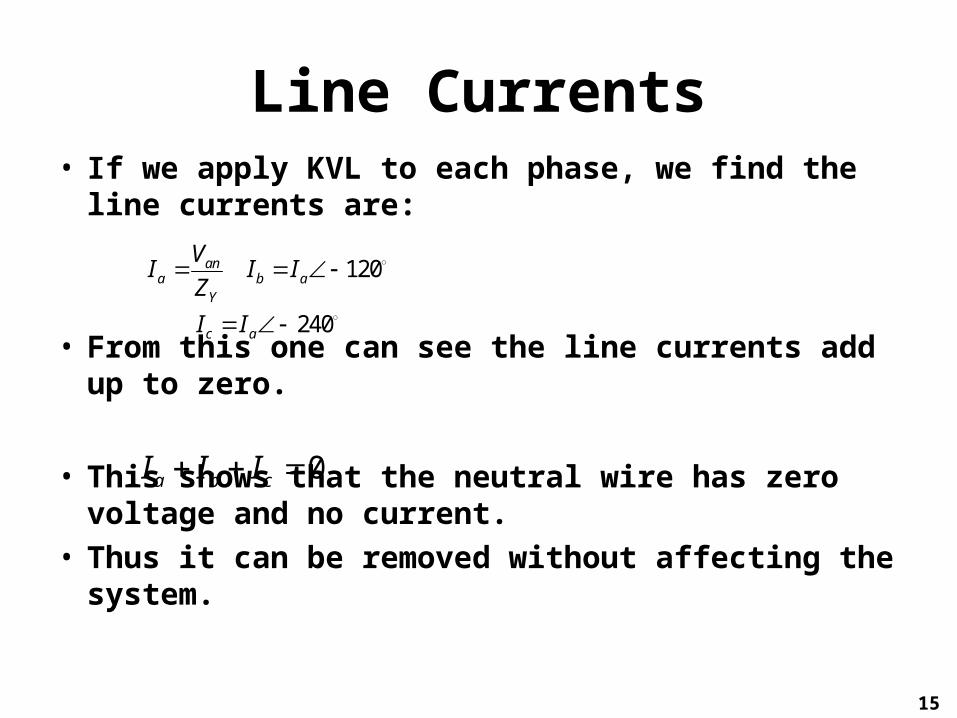
Line Currents• If we apply KVL to each phase, we find the line
currents are:
• From this one can see the line currents add up to zero.
• This shows that the neutral wire has zero voltage and no current.
• Thus it can be removed without affecting the system.
15
120
240
ana b a
Y
c a
VI I I
Z
I I
0a b cI I I

Per Phase Analysis
• An alternative way to analyze the Y-Y circuit is to look at each phase individually.
• Let us look at phase a• The equivalent circuit for that
phase is shown here.• The current for this phase is:
• If the circuit is balanced, only one phase need be analyzed.
16
ana
Y
VI
Z

Balanced Wye-Delta
• This system consists of a balanced Y connected source and a balanced Delta connected load.
• Assuming the positive sequence, the phase voltages are:
• And the line voltages are:
17
0
120 120an p
bn p cn p
V V
V V V V
3 30 3 90 3 150ab P AB bc P BC ca P CAV V V V V V V V V

Balanced Wye-Delta II
• The line voltages are equal to the voltages across the load.
• From this, we can calculate the phase currents:
18
BC CAABAB BC CA
V VVI I I
Z Z Z

Balanced Wye-Delta II
• An alternative way to solve for the phase currents is to apply KVL.
• For example, applying KVL around the loop aABbna gives:
• Or
• This is the more general way to find phase currents.
19
0an AB bnV Z I V
an bn ab ABAB
V V V VI
Z Z Z

Phase to Line Currents
• The line currents can be obtained from the phase currents by applying KCL to nodes A, B, and C
• Since ICA = IAB -240°:
• Thus:
20
a AB CA b BC AB c CA BCI I I I I I I I I
3 30a ABI I
3L pI I

Alternative• An alternate way to analyze the Wye-Delta
circuit is to transform the Delta connected load into a wye connected load.
• Using the Delta-Wye transformation:
• With this circuit now rendered as a Y-Y circuit, single phase analysis can be done
21
3Y
ZZ

Balanced Delta-Delta
• Now we will turn our attention to the Delta-Delta configuration.
• Once again, the goal is to get the phase and line currents.
• Note that Delta configured generators are less typical than the wye because any imbalance in the voltage sources will result in current flowing through the delta loop.
22

Balanced Delta-Delta II
• Assuming a positive sequence, the phase voltages are:
• If line impedances are insignificant, then the impedance voltages are the same as the phase voltages.
23
0
120 120ab p
bc p ca p
V V
V V V V
ab AB bc BC ca CAV V V V V V

Balanced Delta-Delta III
• Hence the phase currents are:
• By applying KCL at the nodes A, B, and C:
• The line current is:
24
ab BC bc CA caABAB BC CA
V V V V VVI I I
Z Z Z Z Z Z
a AB CA b BC AB c CA BCI I I I I I I I I
3L pI I

Balanced Delta-Wye• The last configuration to consider is the
Delta-Wye system.• The phase voltages are the same as the last
case.• There are many ways to get the line currents.• One way is to apply KVL to the loop aANNba
25

Balanced Delta-Wye II
• Applying KVL:
• Thus:
• Keeping in mind that Ib lags Ia by 120°, we can solve for the line current:
26
0Y a b ab pZ I I V V
0pa b
Y
VI I
Z
/ 3 30pa
Y
VI
Z

Convert back to Y-Y
• Another way to solve this system is to convert both the source and load back to a Wye-Wye system.
• The equivalent Wye connected source voltages are:
27
303
150 903 3
pan
p pbn cn
VV
V VV V

Convert back to Y-Y II
• The load conversion goes as the standard delta-wye conversion
• Once this is done, a single phase can be examined to find the line current.
28
/ 3 30pa
Y
VI
Z

Summary:
29

Summary II:
30