Fundamental Concepts - Naif · Navigation and Ancillary Information Facility NIF Fundamental...
38
Navigation and Ancillary Information Facility N IF Fundamental Concepts January 2020
Transcript of Fundamental Concepts - Naif · Navigation and Ancillary Information Facility NIF Fundamental...

Navigation and Ancillary Information Facility
N IF
Fundamental Concepts
January 2020

Navigation and Ancillary Information Facility
N IF
Fundamental Concepts 2
• Preface• Time• Reference Frames• Coordinate Systems• Positions and States• Aberration Corrections
Topics

Navigation and Ancillary Information Facility
N IF
Fundamental Concepts 3
Preface
• This tutorial introduces terminology and concepts used in the later SPICE tutorials.
• Some of this material is more difficult than what follows in later presentations.
– A complete understanding of this material is not essential in order to use SPICE.
• Still, we think this information may be helpful, so… on we go!

Navigation and Ancillary Information Facility
N IF
Fundamental Concepts 4
• An epoch is an instant in time specified by some singular event
– Passage of a star across your zenith meridian– Eclipse of a spacecraft signal as it passes behind a solid body
• Clocks– Clocks count epochs specified by events such as: “regular”
oscillations of a pendulum, quartz crystal, or electromagnetic radiation from a specified source, measured from an agreed upon reference epoch.
– Careful specification of epochs using clocks requires reference to the particular clock and the location of that clock.
• Time Systems– Are agreed upon standards for “naming” epochs, measuring
time, and synchronizing clocks
Time

Navigation and Ancillary Information Facility
N IF
Fundamental Concepts 5
• International Atomic Time (TAI)– Statistical time scale
» Based on data from ~200 atomic clocks in over 50 national laboratories
– Maintained by Bureau International des Poids et Mesures (BIPM)– Unit is the SI (System International) second
» duration of 9192631770 periods of the radiation corresponding to the transition between two hyperfine levels of the ground state of the cesium 133 atom
– TAI is expressed as a count of atomic seconds past the astronomically determined instant of midnight 1 Jan 1958 00:00:00
• Coordinated Universal Time (UTC)– Civil Time at Greenwich England (~GMT)– Usual Calendar Formats plus Hour:Minute:Second.fraction
• Relationship between TAI and UTC– UTC + 10 seconds + number of leap seconds = TAI
» Valid only after Jan 01, 1972
Atomic Time and UTC
Navigation and Ancillary Information Facility
N IF
Fundamental Concepts 6
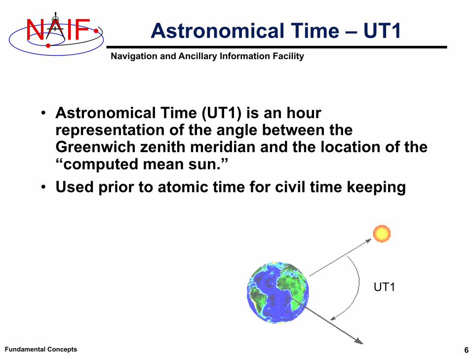
• Astronomical Time (UT1) is an hour representation of the angle between the Greenwich zenith meridian and the location of the “computed mean sun.”
• Used prior to atomic time for civil time keeping
UT1
Astronomical Time – UT1
Navigation and Ancillary Information Facility
N IF
Fundamental Concepts 7
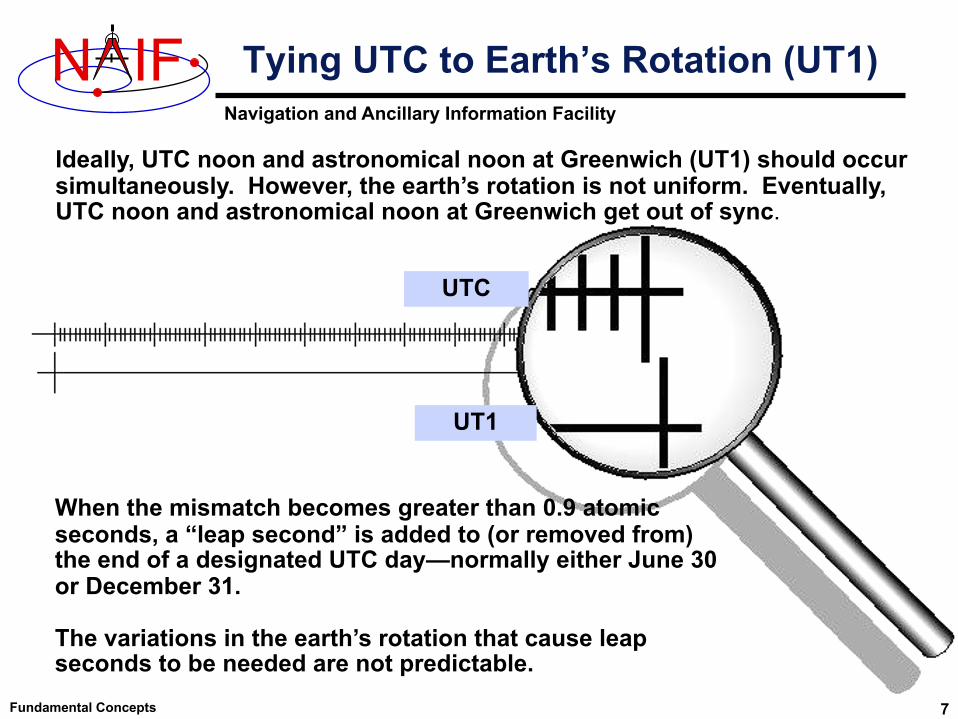
Ideally, UTC noon and astronomical noon at Greenwich (UT1) should occur simultaneously. However, the earth’s rotation is not uniform. Eventually, UTC noon and astronomical noon at Greenwich get out of sync.
When the mismatch becomes greater than 0.9 atomic seconds, a “leap second” is added to (or removed from) the end of a designated UTC day—normally either June 30 or December 31.
The variations in the earth’s rotation that cause leap seconds to be needed are not predictable.
Tying UTC to Earth’s Rotation (UT1)
UT1
UTC
Navigation and Ancillary Information Facility
N IF
Fundamental Concepts 8
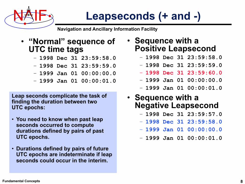
• “Normal” sequence of UTC time tags– 1998 Dec 31 23:59:58.0– 1998 Dec 31 23:59:59.0– 1999 Jan 01 00:00:00.0– 1999 Jan 01 00:00:01.0
• Sequence with a Positive Leapsecond– 1998 Dec 31 23:59:58.0– 1998 Dec 31 23:59:59.0– 1998 Dec 31 23:59:60.0– 1999 Jan 01 00:00:00.0– 1999 Jan 01 00:00:01.0
• Sequence with a Negative Leapsecond– 1998 Dec 31 23:59:57.0– 1998 Dec 31 23:59:58.0– 1999 Jan 01 00:00:00.0
– 1999 Jan 01 00:00:01.0
Leapseconds (+ and -)
Leap seconds complicate the task offinding the duration between two UTC epochs:
• You need to know when past leap seconds occurred to compute durations defined by pairs of past UTC epochs.
• Durations defined by pairs of future UTC epochs are indeterminate if leap seconds could occur in the interim.
Navigation and Ancillary Information Facility
N IF
Fundamental Concepts 9
• Barycentric Dynamical Time (TDB) and Ephemeris Time (ET) are synonyms in SPICE documentation.
• TDB is– a mathematical ideal used in the equations of motion. – used as the independent time variable for many SPICE
subroutine interfaces.– related to Barycentric Coordinate Time (TCB) by an offset and
a scale factor.– TDB advances on average at very close to the same rate as
TAI---the difference is nearly periodic.
Barycentric Dynamical Time
Navigation and Ancillary Information Facility
N IF
Fundamental Concepts 10
• Terrestrial Dynamical Time (TDT)– TDT is the Ideal Time (proper time) on Earth at sea level– TDT = TAI + 32.184 seconds– The IAU has adopted the name “Terrestrial Time” (TT)
» But this is called TDT throughout SPICE documentation• TDB and TDT have nearly the same reference
epoch (approximately 1 Jan 2000, 12:00:00 at Greenwich England), called “J2000.”
• TDB and TDT advance at different rates.– Variations are small: ~ 1.6 milliseconds– Variations are almost periodic with a period of 1 sidereal year
(to first order)– Variations are due to relativistic effects
» TDB = TDT + 0.001657 sin( E + 0.01671sin(E) )• Use of TDT in the SPICE system is quite limited.
– SCLK kernels– Duration computations involving UTC
Terrestrial Dynamical Time
Navigation and Ancillary Information Facility
N IF
Fundamental Concepts
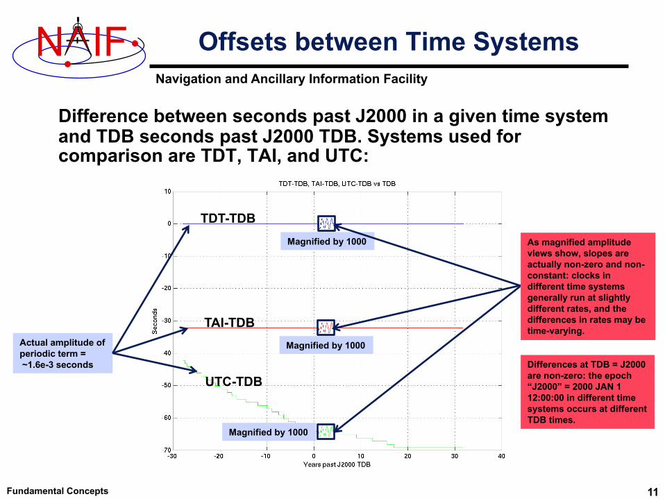
Difference between seconds past J2000 in a given time system and TDB seconds past J2000 TDB. Systems used for comparison are TDT, TAI, and UTC:
Offsets between Time Systems
Actual amplitude of periodic term =~1.6e-3 seconds
Magnified by 1000
TDT-TDB
UTC-TDB
TAI-TDB
As magnified amplitude views show, slopes are actually non-zero and non-constant: clocks in different time systems generally run at slightly different rates, and the differences in rates may be time-varying.
Differences at TDB = J2000 are non-zero: the epoch “J2000” = 2000 JAN 1 12:00:00 in different time systems occurs at different TDB times.
Magnified by 1000
Magnified by 1000
11

Navigation and Ancillary Information Facility
N IF
Fundamental Concepts 12
• Spacecraft have onboard clocks to control scheduling of observations, maneuvers, attitude adjustments, etc.
• Used to time stamp data• Fundamental unit of time is the “tick”
– Smallest increment possible for a spacecraft clock– Nominal tick duration is spacecraft clock dependent
• Spacecraft clock time is a count of ticks since some reference tick.
• The duration of the tick drifts with respect to other time systems because spacecraft clocks are not very stable
Spacecraft Clocks
Navigation and Ancillary Information Facility
N IF
Fundamental Concepts 13
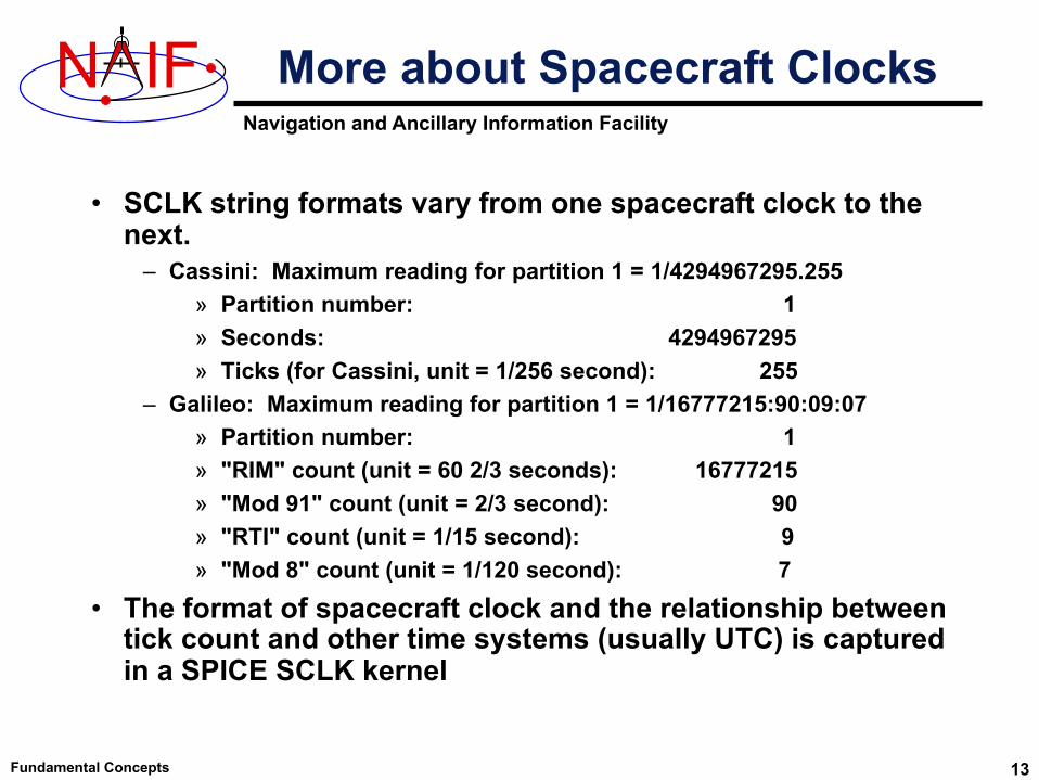
• SCLK string formats vary from one spacecraft clock to the next.
– Cassini: Maximum reading for partition 1 = 1/4294967295.255» Partition number: 1» Seconds: 4294967295 » Ticks (for Cassini, unit = 1/256 second): 255
– Galileo: Maximum reading for partition 1 = 1/16777215:90:09:07» Partition number: 1» "RIM" count (unit = 60 2/3 seconds): 16777215» "Mod 91" count (unit = 2/3 second): 90» "RTI" count (unit = 1/15 second): 9» "Mod 8" count (unit = 1/120 second): 7
• The format of spacecraft clock and the relationship between tick count and other time systems (usually UTC) is captured in a SPICE SCLK kernel
More about Spacecraft Clocks

Navigation and Ancillary Information Facility
N IF
Fundamental Concepts 14
• A reference frame is an ordered set of three mutually orthogonal (possibly time dependent) unit-length direction vectors, coupled with a location called the frame’s “center” or “origin.”
– SPICE documentation frequently uses the shorthand “frame” instead of “reference frame.”
– The ordered set of axes of a reference frame is also called a “basis.”
• A coordinate system specifies the method of locating a point within a reference frame.
SPICE Definitions:Reference Frames & Coordinate Systems
Cartesian coordinates Spherical coordinates
Two examples of coordinate systems
Navigation and Ancillary Information Facility
N IF
Fundamental Concepts 15
• A reference frame’s center is an ephemeris object whose location is coincident with the origin (0, 0, 0) of the frame.
– The center of the IAU_<body> frame is center of mass of <body>.– The center of any inertial frame is (in SPICE) the solar system barycenter.
» True even for frames naturally associated with accelerated bodies, such as MARSIAU.
• A frame’s center plays little role in specification of states– Origin cancels out when doing vector arithmetic
» Whether positions of objects A and B are specified relative to centers C1 or C2 makes no difference:
(A – C1) – ( B – C1 ) = ( A – C2 ) – ( B – C2 ) = A – B– But the center *is* used in computing light time to centers of non-inertial
frames» When the aberration-corrected state of Titan as seen from the Cassini
orbiter is computed in the body-fixed IAU_Titan frame, light time is computed from Titan’s center to the Cassini orbiter, and this light time is used to correct both the state and orientation of Titan.
» (Light time and aberration corrections are discussed later on.)
Reference Frame Center

Navigation and Ancillary Information Facility
N IF
Fundamental Concepts 16
• Inertial– Non-rotating
» With respect to fixed stars– Non-accelerating origin
» Velocity is typically non-zero; acceleration is negligible– Examples:
» J2000 (also called ICRF), B1950• Non-Inertial
– Examples» Body-fixed
• Centered at body center• Topocentric
» Instrument» Dynamic frames
• For example, frames defined by time-dependent vectors
Types of Reference Frames
Navigation and Ancillary Information Facility
N IF J2000 Frame
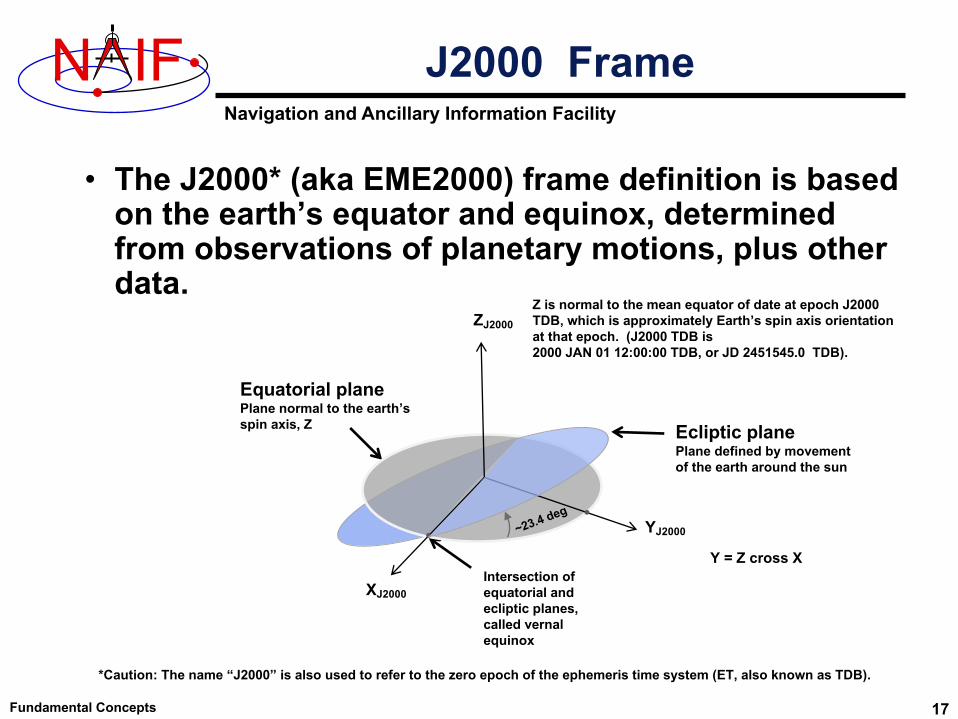
• The J2000* (aka EME2000) frame definition is based on the earth’s equator and equinox, determined from observations of planetary motions, plus other data.
Fundamental Concepts 17
Ecliptic planePlane defined by movement of the earth around the sun
Equatorial planePlane normal to the earth’s spin axis, Z
Intersection ofequatorial and ecliptic planes,called vernalequinox
ZJ2000
XJ2000
YJ2000~23.4 deg
Y = Z cross X
*Caution: The name “J2000” is also used to refer to the zero epoch of the ephemeris time system (ET, also known as TDB).
Z is normal to the mean equator of date at epoch J2000 TDB, which is approximately Earth’s spin axis orientation at that epoch. (J2000 TDB is 2000 JAN 01 12:00:00 TDB, or JD 2451545.0 TDB).
Navigation and Ancillary Information Facility
N IF The ICRF Frame
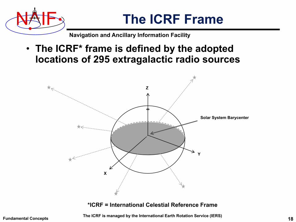
• The ICRF* frame is defined by the adopted locations of 295 extragalactic radio sources
Fundamental Concepts
X
Y
Z
Solar System Barycenter
*ICRF = International Celestial Reference Frame
The ICRF is managed by the International Earth Rotation Service (IERS) 18

Navigation and Ancillary Information Facility
N IF J2000 vs. ICRF
• The realization of ICRF was made to coincide almost exactly with the J2000 frame.
– The difference is very small–a rotation of less than 0.1 arc second– These two frame names are treated synonymously in SPICE
» In reality, any SPICE data said to be referenced to the J2000 frame are actually referenced to the ICRF frame
» For historical and backwards compatibility reasons, only the name “J2000” is recognized by SPICE software as a frame name–not “ICRF”
• No transformation is required to convert SPICE state vectors or orientation data from the J2000 frame to the ICRF.
Fundamental Concepts 19ICRF = International Celestial Reference Frame, defined by the IERSIERS = International Earth Rotation Service

Navigation and Ancillary Information Facility
N IF
Fundamental Concepts 20
• Body-fixed frames are tied to a named body and rotate with it
– The most common names, those for planets, satellites, the sun, and a few asteroids and comets, are hard-coded in SPICE software
» Frame name style is “IAU_body name”• Examples: IAU_MARS, IAU_SATURN
» To see all such names, see:• Frames Required Reading document, or• Latest generic PCK file
– The rotation state (the orientation at time 𝑻) is usually determined using a SPICE text PCK containing data published by the IAU
– The earth and moon are special cases!» IAU_EARTH and IAU_MOON both exist but
generally should NOT be used» See the SPICE tutorial named “lunar-
earth_pck-fk” for the best frames to be used for those bodies
– On very rare occasions a CK is used to provide a body’s rotation state
Body-fixed Frames
Z
YX
•
•
Body-fixed
•
Navigation and Ancillary Information Facility
N IF
Fundamental Concepts 21
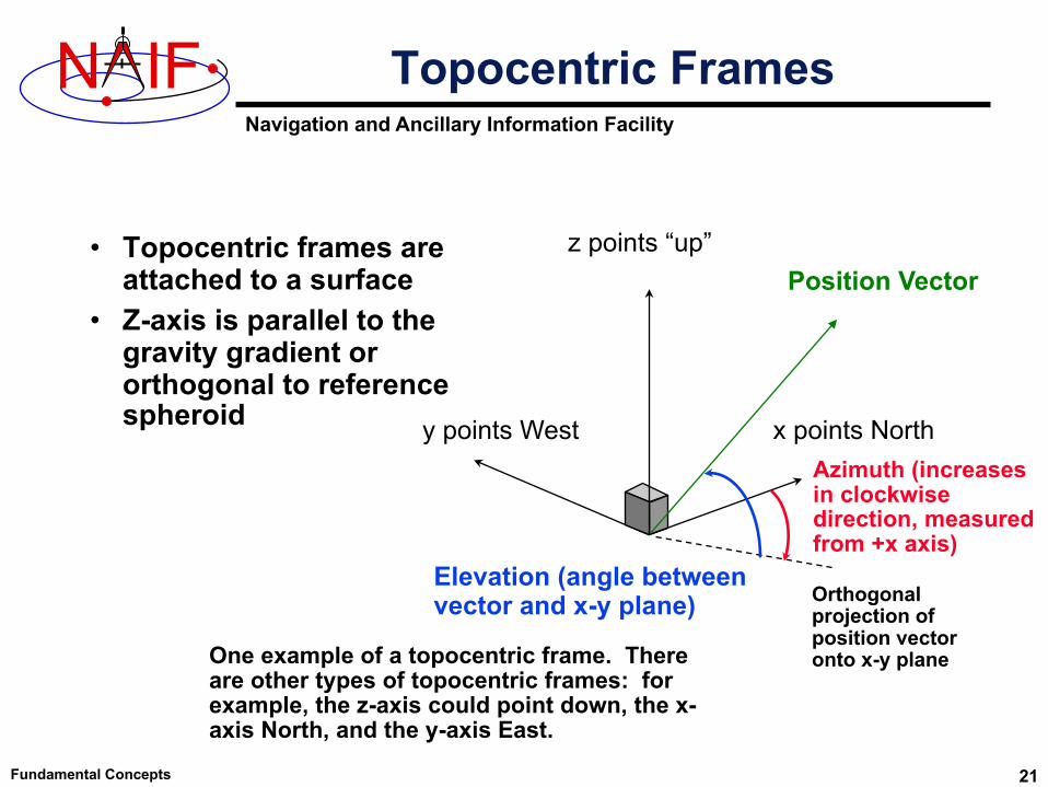
• Topocentric frames are attached to a surface
• Z-axis is parallel to the gravity gradient or orthogonal to reference spheroid x points North
z points “up”
y points WestAzimuth (increasesin clockwise direction, measured from +x axis)
Elevation (angle betweenvector and x-y plane)
Topocentric Frames
One example of a topocentric frame. There are other types of topocentric frames: for example, the z-axis could point down, the x-axis North, and the y-axis East.
Position Vector
Orthogonal projection of position vector onto x-y plane

Navigation and Ancillary Information Facility
N IF
Fundamental Concepts 22
Coordinate System Conventions - 1
• Planetocentric coordinate systems (also known as latitudinal)
– For planets and their satellites the +Z axis (+90 LAT) always points to the north side of the invariable plane (the plane whose normal vector is the angular momentum vector of the solar system)
» Planetocentric longitude increases positively eastward
» Planetocentric latitude increases positively northward
– Dwarf planets*, asteroids and comets spin in the right hand sense about their “positive pole.”
» What the IAU now calls the “positive pole” is still referred to as the “north pole” in SPICE documentation.
» The “positive pole” may point above or below the invariable plane of the solar system (see above).
» This revision by the IAU Working Group (2006) inverts what had been the direction of the north pole for Pluto, Charon and Ida.
– Planetocentric routines are RECLAT/ LATREC, RADREC/RECRAD, DRDLAT/DLATDR
*The dwarf planets are: Ceres, Eris, Haumea, Makemake, Pluto
X
Y
Z

Navigation and Ancillary Information Facility
N IF
Fundamental Concepts 23
Coordinate System Conventions - 2
• Planetodetic coordinate systems– Planetodetic longitude is
planetocentric longitude» increases positively eastward
– Planetodetic latitude » Tied to a reference ellipsoid» For a point on a reference
ellipsoid, the angle measured from the X-Y plane to the surface normal at the point of interest. For other points, equals latitude at the nearest point on the reference ellipsoid
» Latitude increases positively in the +Z direction
• +Z is defined the same as for planetocentric coordinates
– Planetodetic routines are RECGEO/GEOREC, DRDGEO/DGEODR
X
Y
Z

Navigation and Ancillary Information Facility
N IF
Fundamental Concepts 24
Coordinate System Conventions - 3
• Planetographic coordinate systems– For planet and satellite planetographic
coordinate systems:» Planetographic latitude is planetodetic
latitude» Planetographic longitude is usually
defined such that the sub-observer longitude increases with time as seen by a distant, fixed observer in an inertial reference frame
• The earth, moon and sun are exceptions; planetographic longitude is positive east by default
• Planetographic routines are PGRREC/RECPGR
– For dwarf planets, asteroids and comets:» There are multiple, inconsistent
standards! (USNO, IAU, PDS)» NAIF strongly suggests you use only
planetocentric or planetodetic coordinates
• Planetocentric routines are RECLAT/ LATREC, RADREC/RECRAD, DRDLAT/DLATDR
• Planetodetic routines are RECGEO/GEOREC, DRDGEO/DGEODR
X
Y
ZSpin
direction
Distant Observer
.
Navigation and Ancillary Information Facility
N IF
Fundamental Concepts 25
• The state of an object is its position and velocity relative to a second object– In SPICE, these objects are often referred to as “target” and
“observer” or “center”– E.g. Saturn relative to Saturn barycenter; Titan relative to Huygens
probe– A state is always given in the TDB time system (also known as ET)
• In the SPK subsystem a state is a six dimensional vector– First three components are Cartesian position: x, y, z– Second three components are Cartesian velocity: dx/dt, dy/dt, dz/dt– Units are km, km/sec
• A state is specified relative to a reference frame
State Vectors
Navigation and Ancillary Information Facility
N IF
Fundamental Concepts 26
• To perform algebraic operations on states they must be in the same reference frame.
• Position-only frame transformations require only a rotation* matrix given as a function of time.
» PB (t) = RA to B(t) PA(t)
• Position and velocity frame transformations require that we differentiate the above equation
» dPB (t) /dt = dRA to B(t)/dt PA(t) + RA to B(t) d PA(t)/dt
• We can use a 6x6 matrix to combine these two transformations into a single equation
Transforming States
* Assuming both frames are right-handed
Navigation and Ancillary Information Facility
N IF
Fundamental Concepts 27
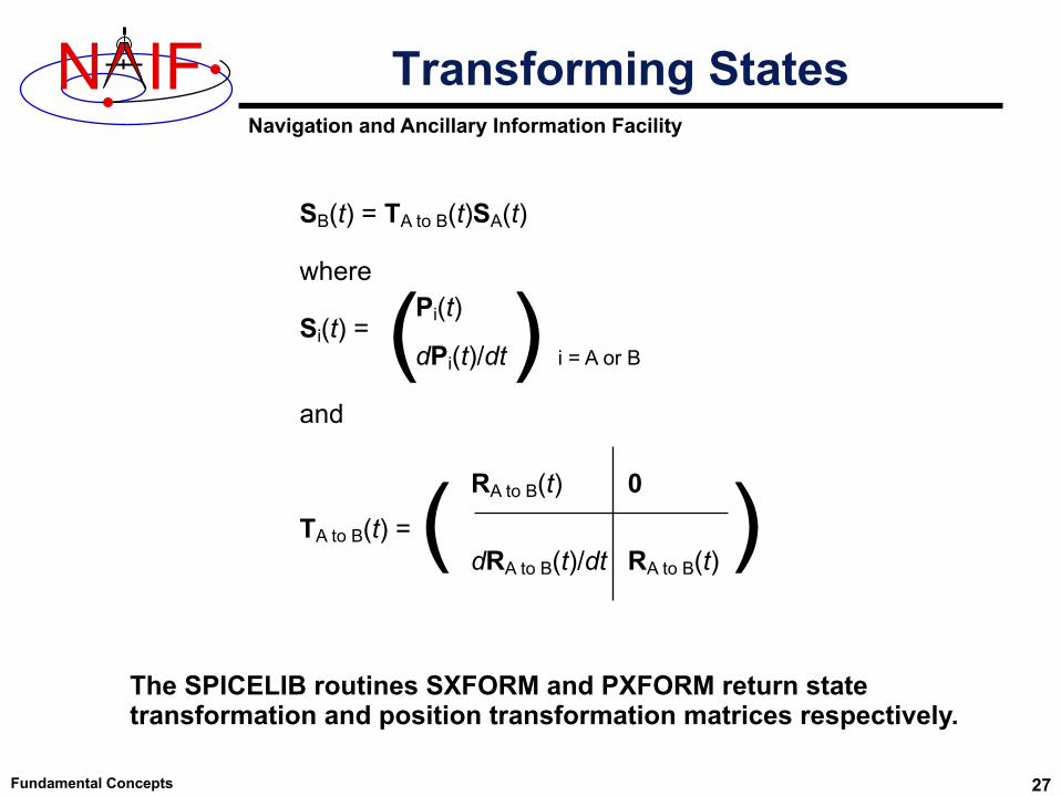
SB(t) = TA to B(t)SA(t)
where
Si(t) =
and
TA to B(t) =
Pi(t)
dPi(t)/dt i = A or B(RA to B(t)
dRA to B(t)/dt RA to B(t)
0( )
)
The SPICELIB routines SXFORM and PXFORM return state transformation and position transformation matrices respectively.
Transforming States
Navigation and Ancillary Information Facility
N IF
Fundamental Concepts 28
• Within the SPICE system, “aberration corrections” are adjustments made to state vectors and time-dependent reference frames to accurately reflect the apparent–as opposed to the actual–state and attitude of a target object as seen from a specified observer at a specified time.
– Actual, uncorrected states from an ephemeris are called “geometric” states.
– When computing state vectors, SPICE users may request geometric or aberration-corrected states.
• Aberration corrections are needed to accurately answer questions such as:
– In which direction must a remote sensing instrument be pointed to observe a target of interest?
– For a given pointing direction and observation time, what target body surface location would be observed by a remote sensing instrument?
– In which direction must an antenna be pointed to transmit a signal to a specified target?
Aberration Corrections: Introduction
Navigation and Ancillary Information Facility
N IF Computing Aberration-corrected States
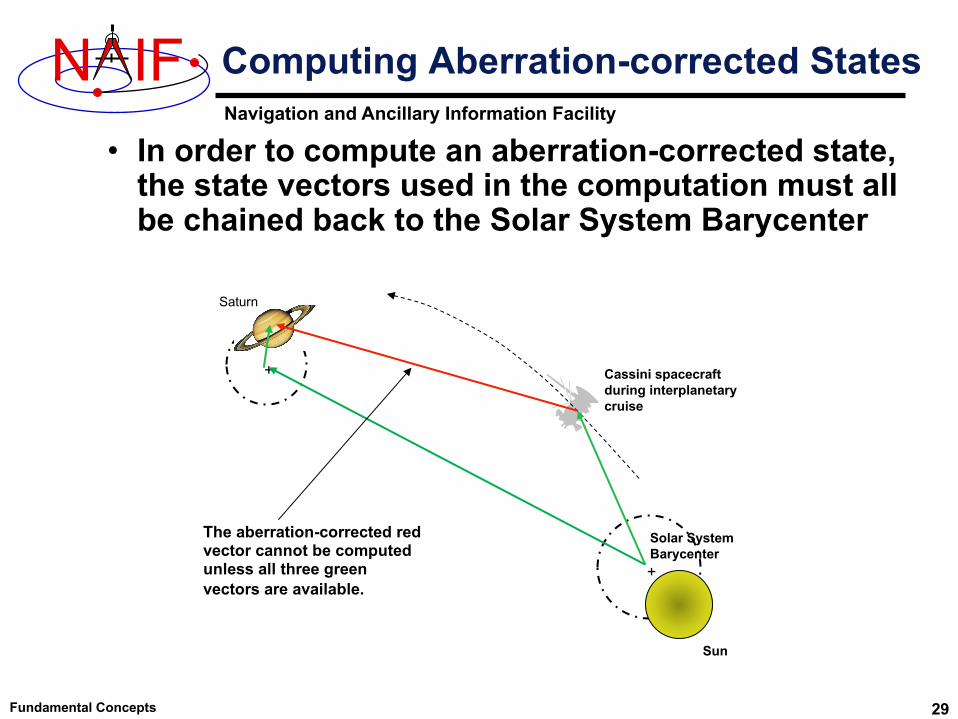
• In order to compute an aberration-corrected state, the state vectors used in the computation must all be chained back to the Solar System Barycenter
Fundamental Concepts 29
+
+
Sun
Solar System Barycenter
Cassini spacecraft during interplanetary cruise
Saturn
The aberration-corrected red vector cannot be computed unless all three green vectors are available.

Navigation and Ancillary Information Facility
N IF
Fundamental Concepts 30
Example: Predicted vs Actual PhotoWe compare the predicted appearance of a photograph from an optical camera against the actual photograph. We show three predictions derived using different aberration corrections: NONE, LT ("light time only"), and LT+S ("light time plus stellar aberration").For each prediction, we use red overlays to indicate the expected location in the photo of the images of an extended target body (for example, a natural satellite), of features on the surface of the target body, and of a star.
NONEPredicted images using uncorrected target position and orientation and uncorrected star direction vector
LTPredicted images using light time-corrected target position and orientation and uncorrected star direction vector
LT+SPredicted images using light time and stellar aberration-corrected target position, light time-corrected target orientation, and stellar aberration-corrected star direction vector

Navigation and Ancillary Information Facility
N IF
Fundamental Concepts 31
Prediction Without Corrections
Predicted target body, surface feature, and star image locations (in red). Actual locations are in blue and black.
Actual body image
Using geometric target positions, target images in photos or other remote-sensing observations don’t appear at their predicted locations.
Actual star
image
Body motion relative to solar
system barycenter

Navigation and Ancillary Information Facility
N IF
Fundamental Concepts 32
Light Time Corrections
Observer’s position at time ET
Target’s (geometric) position and orientation at time ET Target’s position and
orientation at time ET-LT (light time corrected position and orientation)
Light travels this path in LT seconds
At time ET, the observer’s camera records photons emitted from the target at time ET-LT, where LT is the one-way light time. The camera "sees" the target's position and orientation at ET-LT.
Note: The angular separation of the geometric and light time corrected positions as seen by the observer has been exaggerated for readability.
Target’s angular velocity vector
Target’s velocity vector
Target travels this path (along the black
arc) in LT seconds

Navigation and Ancillary Information Facility
N IF
Fundamental Concepts 33
Prediction Using Light Time Corrections
Using the light time corrected target position and orientation, the predicted locations in the photo of the target image and surface features have changed, but the accuracy of the prediction may still be poor.
Actual star
image Actual body image
Body motion relative to solar
system barycenter
Predicted target body, surface feature, and star image locations (in red). Actual locations are in blue and black.

Navigation and Ancillary Information Facility
N IF
Fundamental Concepts 34
Stellar Aberration Correction
Observer’s position at time ET
To the observer, light appears to travel this path
At time ET, the observer’s camera records photons emitted from the target at time ET-LT, where LT is the one-way light time. The vector from the observer at ET to the location of the target at ET-LT is displaced by a physical phenomenon called stellar aberration. The displaced vector yields the apparent position of the target.
Target’s apparent position and orientation
Observer’s velocity relative to Solar System
Barycenter
Note: The angular separation of the geometric, light time corrected, and apparent positions as seen by the observer has been exaggerated for readability.
Target’s position and orientation at time ET. This position is called the geometric or uncorrected position. Target’s position and
orientation at time ET-LT (light time corrected position and orientation)
Velocity component orthogonal to observer-target position
Navigation and Ancillary Information Facility
N IF
Fundamental Concepts 35
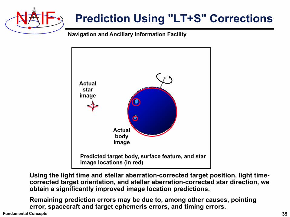
Prediction Using "LT+S" Corrections
Predicted target body, surface feature, and star image locations (in red)
Using the light time and stellar aberration-corrected target position, light time-corrected target orientation, and stellar aberration-corrected star direction, we obtain a significantly improved image location predictions. Remaining prediction errors may be due to, among other causes, pointing error, spacecraft and target ephemeris errors, and timing errors.
Actual star
image
Actual body image
Navigation and Ancillary Information Facility
N IF
Fundamental Concepts 36
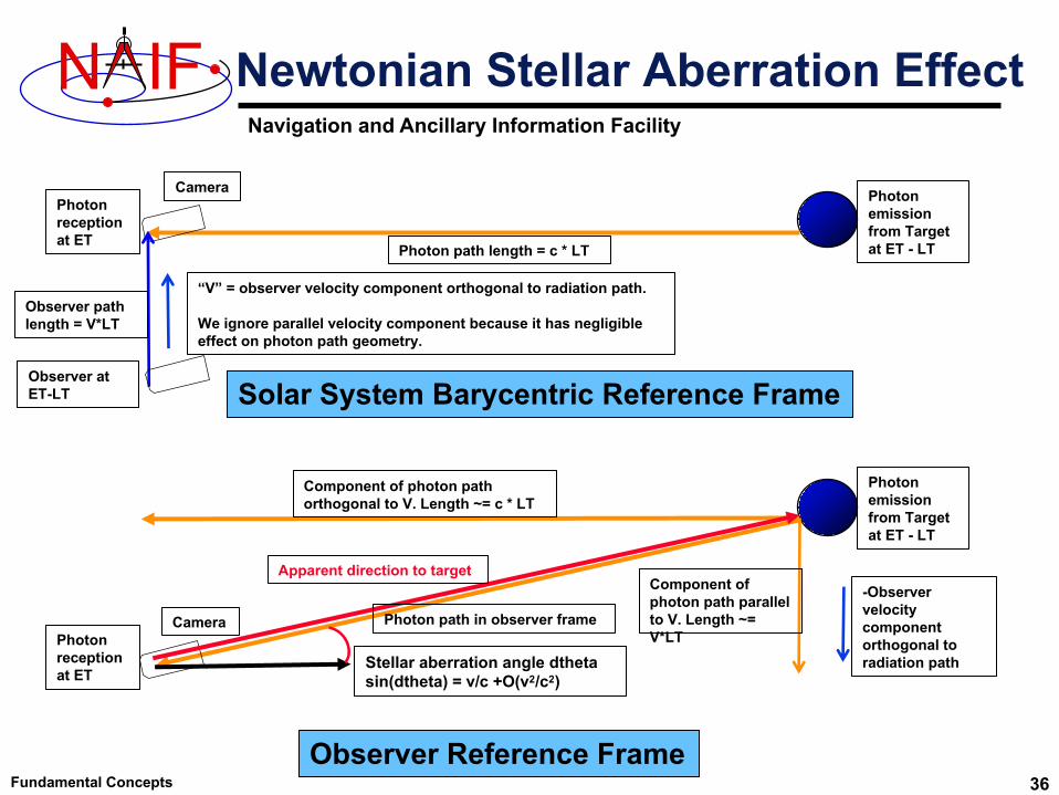
Newtonian Stellar Aberration Effect
Photon emission from Target at ET - LT
Photon reception at ET
Solar System Barycentric Reference Frame
Photon path length = c * LT
Observer path length = V*LT
Observer at ET-LT
Component of photon path parallel to V. Length ~= V*LT
Component of photon path orthogonal to V. Length ~= c * LT
Observer Reference Frame
Photon reception at ET
“V” = observer velocity component orthogonal to radiation path.
We ignore parallel velocity component because it has negligible effect on photon path geometry.
Stellar aberration angle dthetasin(dtheta) = v/c +O(v2/c2)
-Observer velocity component orthogonal to radiation path
Photon emission from Target at ET - LT
Camera
Camera
Apparent direction to target
Photon path in observer frame
Navigation and Ancillary Information Facility
N IF
Fundamental Concepts 37
Effect of Aberration Corrections - 1
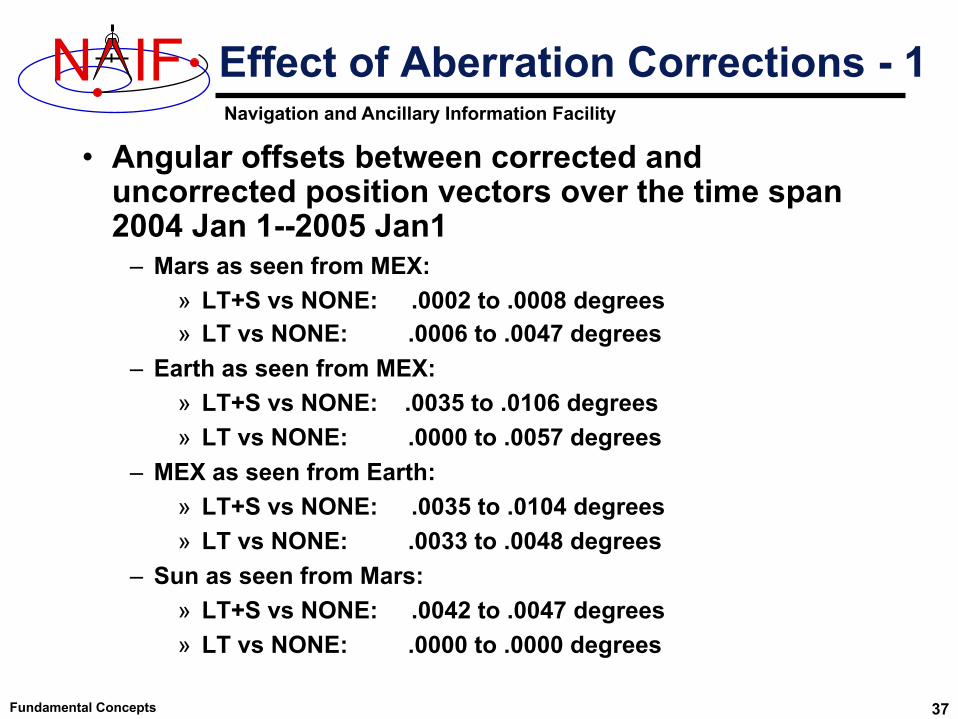
• Angular offsets between corrected and uncorrected position vectors over the time span 2004 Jan 1--2005 Jan1
– Mars as seen from MEX: » LT+S vs NONE: .0002 to .0008 degrees» LT vs NONE: .0006 to .0047 degrees
– Earth as seen from MEX: » LT+S vs NONE: .0035 to .0106 degrees» LT vs NONE: .0000 to .0057 degrees
– MEX as seen from Earth: » LT+S vs NONE: .0035 to .0104 degrees» LT vs NONE: .0033 to .0048 degrees
– Sun as seen from Mars: » LT+S vs NONE: .0042 to .0047 degrees» LT vs NONE: .0000 to .0000 degrees

Navigation and Ancillary Information Facility
N IF
Fundamental Concepts 38
Effect of Aberration Corrections - 2
• Angular offsets between corrected and uncorrected position vectors over the time span 2004 Jan 1--2008 Jan1
– Saturn as seen from CASSINI: » LT+S vs NONE: .0000 to .0058 degrees» LT vs NONE: .0001 to .0019 degrees
– Titan as seen from CASSINI: » LT+S vs NONE: .0000 to .0057 degrees» LT vs NONE: .0000 to .0030 degrees
– Earth as seen from CASSINI: » LT+S vs NONE: .0000 to .0107 degrees» LT vs NONE: .0000 to .0058 degrees
– CASSINI as seen from Earth: » LT+S vs NONE: .0000 to .0107 degrees» LT vs NONE: .0000 to .0059 degrees
– Sun as seen from CASSINI: » LT+S vs NONE: .0000 to .0059 degrees» LT vs NONE: .0000 to .0000 degrees