
Fundamental analysis of the influence of powder ... Plansee Seminar RM 26/1 Fundamental analysis of...
12
19 th Plansee Seminar RM 26/1 Fundamental analysis of the influence of powder characteristics in selective laser melting of molybdenum based on a multi-physical simulation model K.-H. Leitz*, C. Grohs*, P. Singer*, B. Tabernig*, A. Plankensteiner*, H. Kestler*, L. S. Sigl* * Plansee SE, Metallwerk-Plansee-Straße 71, 6600 Reutte, Austria Abstract Selective Laser Melting (SLM) offers great potential for the processing of molybdenum as it allows the production of parts that can hardly be fabricated in a classical way. The workpiece is built up by melting up powder layer by layer. Besides the applied laser parameters, the characteristics of the powder and the deposited powder layer have a crucial influence on the dynamics of the process and the final processing result. In order to get a fundamental understanding of these influences, numerical simulations are a versatile tool as they allow a detailed look on isolated parameters. In this contribution a coupled thermo-fluid dynamical simulation model for SLM is applied for a fundamental analysis of the influence of powder characteristics in SLM of molybdenum. The results allow a deeper insight into the influences of powder particle size and powder particle arrangement on the SLM process and the formation of the molten track. Keywords Selective laser melting, multi-physical simulation, powder, molybdenum, Comsol Multiphysics, Liggghts Selective Laser Melting – A Promising Technology for the Processing of Molybdenum In industrial manufacturing significant changes occur currently, caused by the increasing digitalization of production. Those changes due to the connection between production and information technologies are predicted to be as dramatic as those observed when mechanization, mass production and electronics led to revolutions of industrial fabrication in the past. Therefore, it is generally talked about the fourth industrial revolution or Industry 4.0 [1]. In order to make Industry 4.0 work new manufacturing technologies are required that allow a fast, precise, efficient and flexible fabrication of functional products from digital data. At this additive manufacturing by Selective Laser Melting (SLM) is highly promising as it allows the fabrication of fully functional metal machine and tool parts. SLM offers unique design possibilities at arbitrary lot sizes and is highly material efficient [2]. In SLM a workpiece is built up from a powder bed. A thin powder layer as well as a part of the subjacent layer is molten up by a laser
-
Upload
truongnhan -
Category
Documents
-
view
222 -
download
5
Transcript of Fundamental analysis of the influence of powder ... Plansee Seminar RM 26/1 Fundamental analysis of...
19th Plansee Seminar RM 26/1
Fundamental analysis of the influence of powder characteristics in
selective laser melting of molybdenum based on a multi-physical
simulation model
K.-H. Leitz*, C. Grohs*, P. Singer*, B. Tabernig*, A. Plankensteiner*,
H. Kestler*, L. S. Sigl*
* Plansee SE, Metallwerk-Plansee-Straße 71, 6600 Reutte, Austria
Abstract
Selective Laser Melting (SLM) offers great potential for the processing of molybdenum as it allows the
production of parts that can hardly be fabricated in a classical way. The workpiece is built up by melting
up powder layer by layer. Besides the applied laser parameters, the characteristics of the powder and
the deposited powder layer have a crucial influence on the dynamics of the process and the final
processing result. In order to get a fundamental understanding of these influences, numerical simulations
are a versatile tool as they allow a detailed look on isolated parameters. In this contribution a coupled
thermo-fluid dynamical simulation model for SLM is applied for a fundamental analysis of the influence of
powder characteristics in SLM of molybdenum. The results allow a deeper insight into the influences of
powder particle size and powder particle arrangement on the SLM process and the formation of the
molten track.
Keywords
Selective laser melting, multi-physical simulation, powder, molybdenum, Comsol Multiphysics, Liggghts
Selective Laser Melting – A Promising Technology for the Processing of Molybdenum
In industrial manufacturing significant changes occur currently, caused by the increasing digitalization of
production. Those changes due to the connection between production and information technologies are
predicted to be as dramatic as those observed when mechanization, mass production and electronics
led to revolutions of industrial fabrication in the past. Therefore, it is generally talked about the fourth
industrial revolution or Industry 4.0 [1]. In order to make Industry 4.0 work new manufacturing
technologies are required that allow a fast, precise, efficient and flexible fabrication of functional products
from digital data. At this additive manufacturing by Selective Laser Melting (SLM) is highly promising as it
allows the fabrication of fully functional metal machine and tool parts. SLM offers unique design
possibilities at arbitrary lot sizes and is highly material efficient [2]. In SLM a workpiece is built up from a
powder bed. A thin powder layer as well as a part of the subjacent layer is molten up by a laser

19th Plansee Seminar RM 26/2
controlled by a scanner system. When the material solidifies again, a melt metallurgic connection
between adjacent and subjacent lines is formed. The building platform is lowered, a new powder layer is
delivered and the process starts from the beginning [3]. At this layer-wise 3D printing of massive, metal
free form components can be realized. The principle of SLM is shown in Fig. 1 a. Fig. 1 b shows the SLM
process during operation. Whereas SLM of materials like aluminum, steel, titanium, nickel and cobalt
chromium alloys is already well established and already applied in industrial production, the processing
of molybdenum by SLM is still a big technical challenge as the processing window is significantly
narrower. Nevertheless, for complex workpiece geometries, SLM is an attractive alternative to classical
powder metallurgical fabrication routes and by a proper choice of processing parameters complex
geometrical structures can be fabricated. Fig. 1 c and d show examples of thin walled, tapered grid
structures as well as massive demonstrator parts that were fabricated at Plansee SE by SLM of
molybdenum.
For a successful, stable and repeatable processing of molybdenum by SLM a fundamental process
understanding is essential. For this aim multi-physical transient process simulations are a powerful tool
in order to analyze the process on a mesoscopic level, study defect formation mechanisms and to learn
about the influence of processing parameters and powder characteristics on process dynamics and
processing result. However, modelling of laser beam-matter interaction is a challenging task, as it
requires a coupling between optics, thermo- and fluid-dynamics. Approaches for multi-physical laser
beam-matter interaction modelling have been developed for a variety of laser processes [4–10] including
SLM [11–15]. Similar models have been developed for the electron beam melting process [16–18]. At
Plansee SE a thermo-fluid dynamical simulation model following those approaches was developed and
applied for an analysis of SLM of molybdenum [19–22].
Figure 1: Selective Laser Melting (SLM): (a) technology principle, (b) process during operation and (c, d) molybdenum
demonstrator parts fabricated by SLM at Plansee SE.

19th Plansee Seminar RM 26/3
Multi-Physical Simulation Model for Selective Laser Melting
The multi-physical simulation model for SLM is based on Comsol Multiphysics. It includes the absorption
of laser radiation on the metal surface, conductive and convective heat transfer in metal and atmosphere
as well as melting, solidification, evaporation and condensation processes. The thermo-fluid dynamical
multi-phase description is based on the phase field approach [23]. Depending on the temperature the
model distinguishes between solid, liquid and vapor metal. The solid metal is treated as a high viscous
fluid and the surface tension is restricted to the liquid phase. Evaporation modelling takes into account
the density change between solid and vapor as well as the resulting mass flux by following an approach
described in [24]. Fig. 2 shows a result obtained with the simulation model for SLM of steel at typical
processing parameters for this material and demonstrates the included physics. The model geometry
consists of a powder layer on a massive base plate. The laser radiation is absorbed on the top surface of
the metal powder. The material heats up, a melt pool is formed and evaporation occurs. The laser moves
along the powder bed and when the material solidifies again, the molten track is formed.
The simulation model uses temperature dependent material data taken from [25–29] (see Table I). A
detailed description of the simulation model, the contained physics and its implementation in Comsol
Multiphysics can be found in [22]. In the past the model was applied in order to analyze the influence of
process parameters in line and layer buildup from steel and molybdenum [19–21]. Fig. 3 shows
simulation results for SLM of molybdenum at standard parameters for volume buildup. It was shown that
the model is able to describe material specific differences in SLM. Whereas for steel at typical
processing parameters there is a long melt pool and evaporation occurs (compare Fig. 2), for
molybdenum the melt pool is significantly shorter and no evaporation can be observed in the simulation
at the regarded parameters (compare Fig. 3). In accordance to experimental data the simulation results
showed that for molybdenum the dependency of line width and surface roughness on the power P [W] is
severely pronounced, whereas for steel the energy input ρE [J m⁄ ] is the dominant process parameter.
This is due to the high thermal conductivity of molybdenum [19–21].
Figure 2: Multi-physical simulation model for SLM (SLM of 40 µm steel powder at standard parameters for volume buildup
(standard power P0,steel and standard energy input ρE0,steel)).

19th Plansee Seminar RM 26/4
Table I: Temperature dependent material data for molybdenum and air atmosphere [25–29].
Figure 3: Simulation results for SLM of 40 µm molybdenum powder at standard parameters for volume buildup (standard
power P0,Mo and standard energy input ρE0,Mo): (a) line buildup and (b) layer buildup.
Simulation Results and Discussion
Beside material and processing parameters, in SLM the process dynamics and the processing result are
also significantly determined by the characteristics of the deposited powder layer. Therefore, the multi-
physical simulation model for SLM described in the previous section shall be applied as follows in order
to analyze the influence of powder size and arrangement in SLM of molybdenum. Beside regular
arrangements of powder particles in the powder bed (i.e. periodic simple cubic packaging), a more
realistic powder distribution with irregular powder packaging obtained from a discrete element simulation
model shall be considered.
Idealized Powder Arrangement
In a first step four idealized molybdenum powder arrangements on a massive base plate were
considered in order to analyze the influence of particle size, layer thickness and packing density. The
following powder configurations were compared to each other: one and two layers of simple cubic
arranged 20 µm powder, one simple cubic layer of 40 µm powder and one layer of simple cubic 20 µm
powder with one line of particles missing. Emanating from standard energy input ρE0,Mo and standard

19th Plansee Seminar RM 26/5
power P0,Mo for volume buildup from molybdenum, the influences of a reduced relative energy input
ρE ρE0,Mo⁄ and a reduced relative power P P0,Mo⁄ were analyzed. Relative energy input ρE ρE0,Mo⁄ was
varied from 100 % to 44 %, the relative power P P0,Mo⁄ from 100 % to 50 %. The simulated molten tracks
and cross sections along the processing axis at the borders of the regarded parameter window are
shown in Figs. 4 – 7. In Fig. 8 width and depth of the molten tracks are plotted for the regarded powder
configurations and parameter sets. Width was defined as the difference of maximum and minimum y
coordinate of the simulated molten track. Melting depth was measured with respect to the original
substrate surface at z = 0 m.
Width and depth of the molten tracks of the simple cubic layer of 20 µm powder show no significant
dependence on the energy input, but depend strongly on the power (compare Fig. 8). This result is in
accordance to earlier results on the influence of processing parameters in SLM of molybdenum [18, 19].
Whereas at a reduced relative energy input of ρE ρE0,Mo⁄ = 44 % the width of the molten track is
comparable to that obtained at standard processing parameters along with still good connection between
molten track and substrate, a reduced relative power of P P0,Mo⁄ = 50 % is no longer sufficient to
completely melt up the particles in the simulation and no connection to the substrate is obtained (see
Fig. 4).
For two layers of simple cubic 20 µm powder the widths of the molten tracks are slightly higher as the
energy removal in a thicker powder layer is worse. Therefore, in contrast to one powder layer, even at a
reduced relative power of P P0,Mo⁄ = 50 % still a significant amount of powder is molten up, even if no
connection to the substrate is obtained (compare Fig. 5). Compared to the previous regarded powder
configuration the absolute value of melting depth is smaller as more powder materials needs to be
molten up. Furthermore, a slight dependence of width and depth of the molten track on the energy input
is obtained, whereas power dependency is less pronounced (compare Fig. 8). This can be explained by
the effectively lower thermal conductivity of the powder bed, leading to a more pronounced energy input
dependency [19, 20].
Figure 4: Simulation results for molten tracks generated by SLM of one simple cubic layer of 20 µm molybdenum powder:
(a) ρE ρE0,Mo⁄ = 100 %, P P0,Mo⁄ = 100 %, (b) ρE ρE0,Mo⁄ = 44 %, P P0,Mo⁄ = 100 % and (c) ρE ρE0,Mo⁄ = 100 %,
P P0,Mo⁄ = 50 %.

19th Plansee Seminar RM 26/6
Figure 5: Simulation results for molten tracks generated by SLM of two simple cubic layers of 20 µm molybdenum powder:
(a) ρE ρE0,Mo⁄ = 100 %, P P0,Mo⁄ = 100 %, (b) ρE ρE0,Mo⁄ = 44 %, P P0,Mo⁄ = 100 % and (c) ρE ρE0,Mo⁄ = 100 %,
P P0,Mo⁄ = 50 %.
Figure 6: Simulation results for molten tracks generated by SLM of one simple cubic layer of 40 µm molybdenum powder:
(a) ρE ρE0,Mo⁄ = 100 %, P P0,Mo⁄ = 100 %, (b) ρE ρE0,Mo⁄ = 44 %, P P0,Mo⁄ = 100 % and (c) ρE ρE0,Mo⁄ = 100 %,
P P0,Mo⁄ = 50 %.
The melt pool widths for one simple cubic layer of 40 µm powder are slightly higher than for one layer of
finer powder particles. At a relative power of P P0,Mo⁄ = 100 % connection between molten track and
substrate is obtained, whereas at a lower relative power of P P0,Mo⁄ = 50 % the powder particles are not
molten up completely. Beside this the molten tracks show higher width variations caused by wetting of
neighboring powder particles (compare Fig 6). It becomes obvious that bigger particles in the powder
layer are critical as incomplete melting can lead to insufficient connection of powder layers. Furthermore,
line roughness can be higher due to wetting effects and partially molten adhering particles. The energy
input dependency of the 40 µm powder is on a similar scale as for the two layers of 20 µm powder,
whereas the power dependency is comparable to that of one layer of 20 µm powder (compare Fig 8).
Formation of track width and depth of the fourth considered powder configuration with a line defect in a
simple cubic layer of 20 µm powder are on the same scale as those of the first one (compare Fig 8).
However, at the position of the line defect the molten track shows a necking as there is less material to
be melted and the energy removal through the substrate is more efficient (compare Fig 7). These results
demonstrate that a loose or irregular powder arrangement in SLM incorporates the risk of line width
variations or, even worse, an interruption of the molten track.

19th Plansee Seminar RM 26/7
Figure 7: Simulation results for molten tracks generated by SLM of one simple cubic layer of 20 µm molybdenum powder with a
line defect: (a) ρE ρE0,Mo⁄ = 100 %, P P0,Mo⁄ = 100 %, (b) ρE ρE0,Mo⁄ = 44 %, P P0,Mo⁄ = 100 % and (c)
ρE ρE0,Mo⁄ = 100 %, P P0,Mo⁄ = 50 %.
Figure 8: Width and depth of lines fabricated by SLM obtained from the simulation model for different powder configurations
(sc20: 1 simple cubic layer of 20 µm powder, 2sc20: 2 simple cubic layers of 20 µm powder, sc40: 1 simple cubic
layer of 40 µm powder, sc20defect: 1 simple cubic layer of 20 µm powder with a line defect): (a) energy input
dependency and (b) power dependency.
The simulation results obtained for the four idealized powder configurations clearly demonstrate that size
and arrangement of the powder have a significant influence on the SLM process and the processing
result. A multi-physical simulation based analysis of SLM must not only look at processing parameters
but also needs to take into account the morphological characteristics of the powder layer. Therefore, in
the following a realistic powder distribution with irregular particle arrangement shall be considered.
Realistic Powder Arrangement
Getting information about the 3D powder arrangement in an SLM powder layer by experimental methods
is not trivial. Other authors have used random packing algorithms [15–18] or discrete element modelling
[14, 20] to generate a realistic powder distribution. In this work also a discrete element based particle
modelling approach was chosen. For this purpose the open source discrete element method particle

19th Plansee Seminar RM 26/8
simulation software LIGGGHTS (LAMMPS Improved for General Granular and Granular Heat Transfer
Simulations) was applied. In order to generate a covering thin powder layer, three wipes of a blade with
a gap width of 40, 80 and 120 µm were simulated in the particle simulation. Before each wipe
molybdenum powder was inserted with a medium particle size of 20 µm. Fig. 9 shows intermediate
particle configurations at four different time instants of the third wipe of the discrete element particle
simulation. From this calculated particle distribution a volume of 500 µm x 220 µm x 130 µm was cut out
and taken as an initial geometry for the multi-physical simulation model for SLM. Fig. 10 shows different
time steps during line fabrication from this more realistic powder distribution with irregular particle
arrangement at standard parameters for volume buildup.
It can be seen that powder particle arrangement significantly influences the process dynamics in SLM.
Larger particles need more energy to melt up and wetting of adjacent particles influences the fluid
dynamics in the melt pool. The molten tracks obtained from the simulation at the regarded parameter
sets are shown in Fig. 11. Compared to the idealized simple cubic powder distributions, the molten
tracks obtained from the realistic powder arrangements show much more irregularities, both in shape
and topology of the molten track. Melting depth variations are higher compared to an idealized simple
cubic powder arrangement. Furthermore, line width variations occur due to wetting of big neighboring
particles.
Figure 9: Discrete element simulation results for different time instants (time t1 < t2 < t3 < t4) of the powder deposition process.

19th Plansee Seminar RM 26/9
Figure 10: Simulation results for different stages (time t1 < t2 < t3 < t4) of line buildup by SLM of molybdenum powder
(�̅� = 20 µ𝑚) with a realistic powder arrangement at standard parameters for volume buildup (standard power P0,Mo
and standard energy input ρE0,Mo).
Figure 11: Simulation results for molten tracks generated by SLM of molybdenum powder with a realistic powder arrangement:
(a) ρE ρE0,Mo⁄ = 100 %, P P0,Mo⁄ = 100 %, (b) ρE ρE0,Mo⁄ = 44 %, P P0,Mo⁄ = 100 % and (c) ρE ρE0,Mo⁄ = 100 %,
P P0,Mo⁄ = 50 %.
19th Plansee Seminar RM 26/10
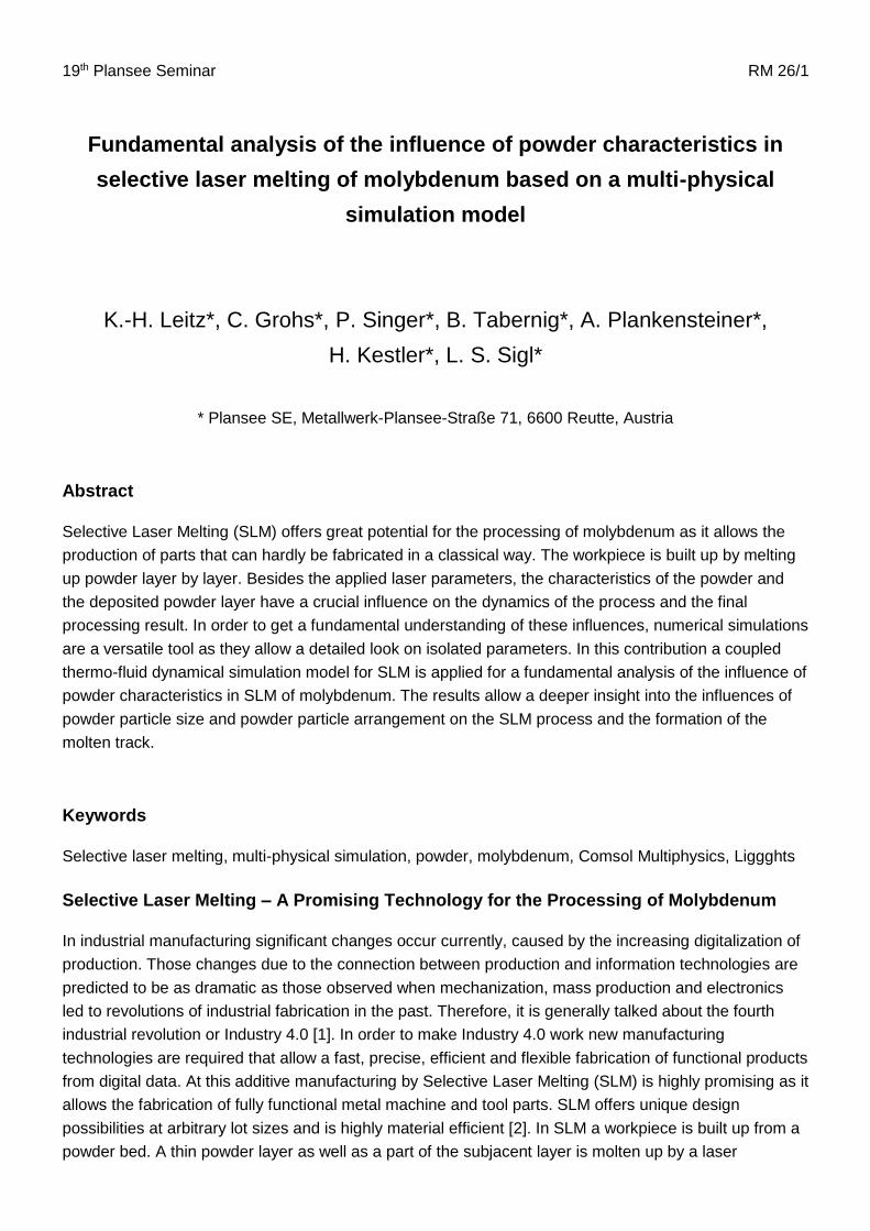
Figure 12: Scanning electron microscope images and microsections of lines fabricated by SLM of molybdenum powder: (a)
ρE ρE0,Mo⁄ = 100 %, P P0,Mo⁄ = 100 %, (b) ρE ρE0,Mo⁄ = 44 %, P P0,Mo⁄ = 100 % and (c) ρE ρE0,Mo⁄ = 100 %,
P P0,Mo⁄ = 50 %.
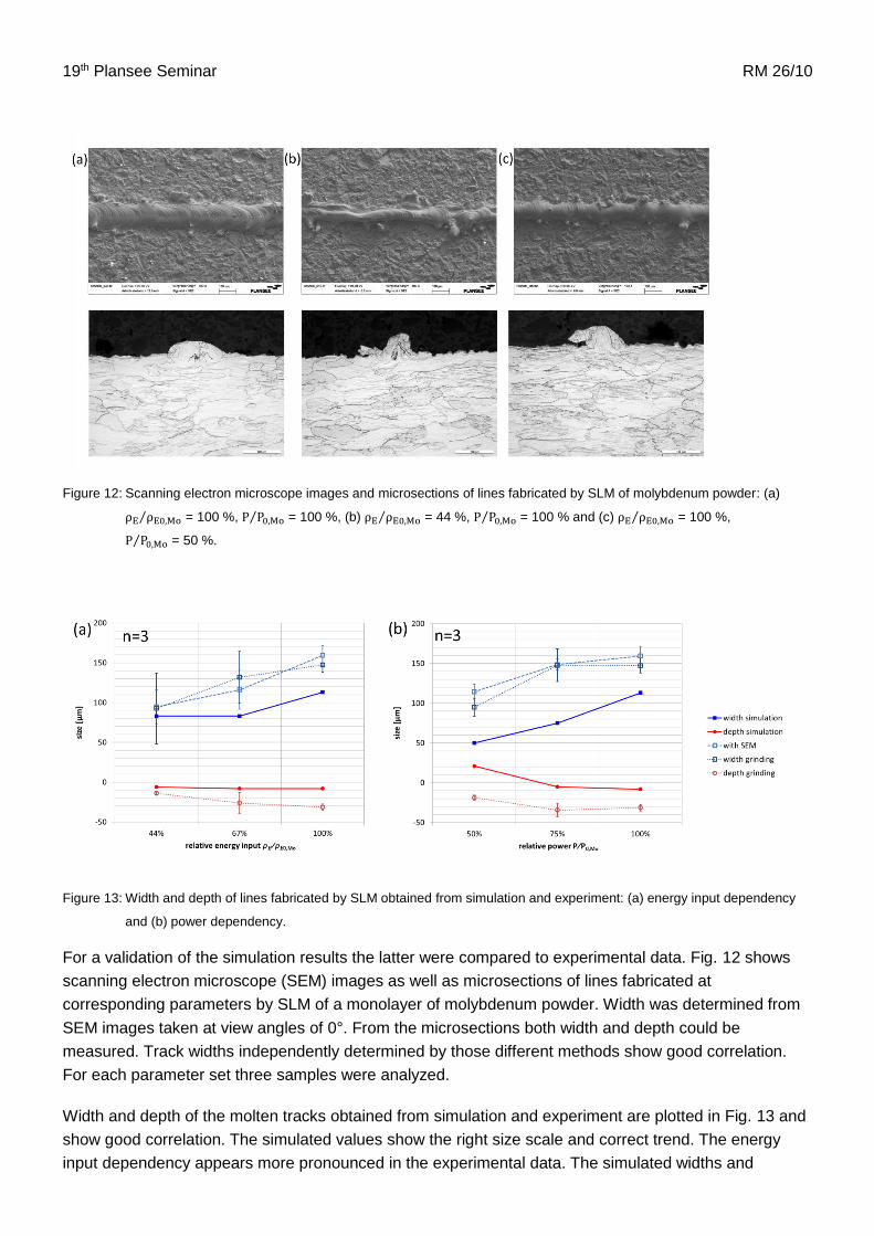
Figure 13: Width and depth of lines fabricated by SLM obtained from simulation and experiment: (a) energy input dependency
and (b) power dependency.
For a validation of the simulation results the latter were compared to experimental data. Fig. 12 shows
scanning electron microscope (SEM) images as well as microsections of lines fabricated at
corresponding parameters by SLM of a monolayer of molybdenum powder. Width was determined from
SEM images taken at view angles of 0°. From the microsections both width and depth could be
measured. Track widths independently determined by those different methods show good correlation.
For each parameter set three samples were analyzed.
Width and depth of the molten tracks obtained from simulation and experiment are plotted in Fig. 13 and
show good correlation. The simulated values show the right size scale and correct trend. The energy
input dependency appears more pronounced in the experimental data. The simulated widths and

19th Plansee Seminar RM 26/11
absolute melting depths are slightly smaller than measured in experiment. This can be explained by
discretization errors in the simulation leading to an overestimation of heat conduction losses.
Conclusions
Multi-physical modelling is a powerful tool to get a fundamental understanding of SLM. The presented
coupled thermo-fluid dynamical simulation model is able to describe the influence of material, processing
parameters and powder characteristics on the process dynamics and the processing result in SLM. The
results demonstrate that the characteristics of the powder layer have a significant influence on the
processing result in SLM of molybdenum. Processing parameters need to be adapted to the
characteristics of the powder layer in order to assure a connection between adjacent and superimposed
molten tracks. Variations in powder particle size as well as imperfections in the powder layer can lead to
variations in the width of the molten track or insufficient connection between the layers. Due to the
smaller melt pool in SLM of molybdenum the process is more sensitive to the morphological
characteristics of the powder bed compared to other materials. Therefore, in SLM of molybdenum a high
quality, customized powder and a proper choice of processing parameters are essential to obtain the
high quality and repeatable processing result required in industrial fabrication.
References
1. H. Kagemann, W. Wahlster and J. Heblig, Final report of the Industrie 4.0 Working Group, (2013)
2. R. Schiffler, VDI Nachrichten 15, pp. 22–23, (2015)
3. R. Poprawe, Lasertechnik für die Fertigung, Springer Verlag, (2015)
4. M. Geiger, K.-H. Leitz, H. Koch and A. Otto, Production Engineering 3, pp. 127–136, (2009)
5. A. Otto, H. Koch, K.-H. Leitz and M. Schmidt, Physics Procedia 12, pp. 11–20, (2011)
6. K.-H. Leitz, H. Koch, A. Otto and M. Schmidt, Applied Physics A 106, pp. 885–891, (2012)
7. K.-H. Leitz, Mikro- und Nanostrukturierung mit kurz und ultrakurz gepulster Laserstrahlung,
Meisenbach Verlag, (2013)
8. S. Kohl, K.-H. Leitz, M. Schmidt, Proceedings of the 37th MATADOR Conference, Manchester, UK,
(2012)
9. M. Dobler, K.-H. Leitz, A. Otto, M. Schmidt, Proceedings of the ICALEO 2013, Miami, USA, (2013)
10. M. Courtois, M. Carin, P. Le Masson, S. Gaied and M. Balabane, Journal of Laser applications 26,
042001, (2014)
11. F.-J. Gürtler, M. Karg, K.-H. Leitz and M. Schmidt, Physics Procedia 41, pp. 874–879, (2013)
12. F.-J. Gürtler, M. Karg, M. Dobler, S. Kohl, I. Tzivilsky and M. Schmidt, Solid freeform fabrication
Symposium, Austin, USA (2014)
13. S. A. Khairallah, A.T. Anderson, A. Rubenchik and W.E. King, Acta Materialia 108, pp. 36–45, (2016)
14. J. Zielinski, H.-W. Mindt, M. Megahed and S. Vervoort, Proceedings of the MAMC 2016, 24–25
November 2016, Linz, Austria, (2016)

19th Plansee Seminar RM 26/12
15. C. Panwisawas, C. Qiu, M. J. Anderson, Y. Sovani, R. P. Turner, M. M. Attallah, J. W. Brooks, H. C.
Basoalto, Computational Materials Science 126, pp. 479–490, (2017)
16. E. Attar, Simulation of Selective Electron Beam Melting Process, Dissertation Universität Erlangen-
Nürnberg, (2011)
17. C. Körner, A. Bauereiß and A. Attar, Modelling and Simulation in Materials Science and Engineering
21, 085011, (2013)
18. A. Bauereiß, T. Scharowsky and C. Körner, Journal of Materials Processing Technology 214, pp.
2522–2528, (2014)
19. K.-H. Leitz, P. Singer, A. Plankensteiner, B. Tabernig, H. Kestler and L.S. Sigl, Proceedings of Euro
PM2015, 4–7 October 2015, Reims, France, (2015)
20. K.-H. Leitz, P. Singer, A. Plankensteiner, B. Tabernig, H. Kestler and L.S. Sigl, Metal Powder Report,
(2016) - in press
21. K.-H. Leitz, P. Singer, A. Plankensteiner, B. Tabernig, H. Kestler and L.S. Sigl, Proceedings of the
MAMC 2016, 24–25 November 2016, Linz, Austria, (2016)
22. K.-H. Leitz, P. Singer, A. Plankensteiner, B. Tabernig, H. Kestler and L.S. Sigl, Proceedings of the
2016 Comsol Conference, 12-14 October 2016, Munich, Germany, (2016)
23. P. Yue, J. J. Fengn, C. Liu and J. Shen, J. Fluid Mech. 515, pp. 293–317, (2004)
24. Y. Sun and C. Beckermann, Physica D 198, pp. 281–308, (2004)
25. Comsol Multiphysics Material Library Version 5.2, © 1998-2014 COMSOL AB
26. C.J. Smithells, Metals Reference Book, Butterworth, (1967)
27. H. Stöcker, Taschenbuch der Physik, Harri Deutsch Verlag, (2000)
28. P.-F. Paradis, T. Ishikawa and N. Koike, International Journal of Refractory Metals & Hard Materials
25, pp. 95–100, (2007)
29. W.D. Wood, H.W. Deem and C.F. Lucks, Handbook of High-Temperature Materials – Thermal
Radiative Properties, Plenum Press, (1964)
30. E. J. R. Parteli and T. Pöschel, Powder Technology, pp. 96–102, (2016)