Functions of Building Automation and Control Systems · The functions of Building Automation and...
40
Functions of Building Automation and Control Systems BACHELORARBEIT zur Erlangung des akademischen Grades Bachelor of Science im Rahmen des Studiums Technische Informatik eingereicht von Thomas Wimmer Matrikelnummer 0525006 am Institut f ¨ ur Rechnergest ¨ utzte Automation Betreuung: Ao.Univ.Prof. Dipl.-Ing. Dr.techn. Wolfgang Kastner Mag. Dipl.-Ing. Fritz Praus Wien, 30.06.2010 (Unterschrift Verfasser) (Unterschrift Betreuer) Technische Universit¨ at Wien A-1040 Wien Karlsplatz 13 Tel. +43/(0)1/58801-0 http://www.tuwien.ac.at
Transcript of Functions of Building Automation and Control Systems · The functions of Building Automation and...

Functions of Building Automationand Control Systems
BACHELORARBEIT
zur Erlangung des akademischen Grades
Bachelor of Science
im Rahmen des Studiums
Technische Informatik
eingereicht von
Thomas WimmerMatrikelnummer 0525006
amInstitut fur Rechnergestutzte Automation
Betreuung:Ao.Univ.Prof. Dipl.-Ing. Dr.techn. Wolfgang KastnerMag. Dipl.-Ing. Fritz Praus
Wien, 30.06.2010(Unterschrift Verfasser) (Unterschrift Betreuer)
Technische Universitat WienA-1040 Wien Karlsplatz 13 Tel. +43/(0)1/58801-0 http://www.tuwien.ac.at

Functions of Building Automation andControl Systems
Kurzfassung
In den letzten Jahren wurden die Schlagworte Smart Home und Smart Building immerpopularer. Dies ist einerseits auf das immer starker werdende Energiebewusstsein dereinzelnen Personen und Firmen zuruckzufuhren als auch auf den steigenden Anspruchauf Komfort in den eigenen vier Wanden bzw. in Buroraumlichkeiten. Um die Imple-mentierung eines Automationssystems zu vereinfachen, wurden in den letzten Jahrenauch Normen zu diesem Thema veroffentlicht.In dieser Arbeit wird auf zwei dieser Normen, DIN EN ISO 16484-3 [1] und VDI3814-1 [5], konkret Bezug genommen. Es wird ein kurzer Einblick in die behandeltenThemen gegeben und im Anschluss auf die Unterschiede in den Normen eingegan-gen. Desweiteren wird die Funktionsliste dieser beiden Normen in einem praktischenBeispiel an einem Gebaudeautomationsmodell des Institutes fur Rechnergestutzte Au-tomation angewendet. Dieses Modell ist auch Bestandteil des letzten Teils, in welchemProdukte der Firma Saia-Burgess [2] dazu verwendet werden, das Modell zu steuernund zu regeln.
i

Functions of Building Automation andControl Systems
Abstract
Smart buildings and homes have become increasingly popular within the last few years.This is because energy saving is becoming gradually more important for individuals andcompanies, and an increased need for comfort has risen in this century. Some standardsare published to make an implementation of building automation and control systems(BACS) easier.This thesis shortly describes two of them, namely DIN EN ISO 16484-3 and VDI 3814-1.A list of the included topics is presented and a short comparison of both standards isoutlined. As a practical part, the BACS function list is used for a heating ventilation andair conditioning (HVAC) model of the Institute of Computer Aided Automation, whichis also part of the last topic, where this model is used in combination with products ofthe company Saia-Burgess.
ii

Contents1 Introduction 1
1.1 Motivation . . . . . . . . . . . . . . . . . . . . . . . . . . . . . . . . . 11.2 Objectives . . . . . . . . . . . . . . . . . . . . . . . . . . . . . . . . . 11.3 Structure of the thesis . . . . . . . . . . . . . . . . . . . . . . . . . . . 2
2 Standards 32.1 DIN EN ISO 16484-3 . . . . . . . . . . . . . . . . . . . . . . . . . . . 32.2 VDI 3814-1 . . . . . . . . . . . . . . . . . . . . . . . . . . . . . . . . 52.3 Analysis . . . . . . . . . . . . . . . . . . . . . . . . . . . . . . . . . . 72.4 BACS function list . . . . . . . . . . . . . . . . . . . . . . . . . . . . 7
3 Saia-Burgess 143.1 Introduction . . . . . . . . . . . . . . . . . . . . . . . . . . . . . . . . 143.2 Configuration . . . . . . . . . . . . . . . . . . . . . . . . . . . . . . . 173.3 Exercises . . . . . . . . . . . . . . . . . . . . . . . . . . . . . . . . . 23
3.3.1 Exercise 1 . . . . . . . . . . . . . . . . . . . . . . . . . . . . . 233.3.2 Exercise 2 . . . . . . . . . . . . . . . . . . . . . . . . . . . . . 263.3.3 Exercise 3 . . . . . . . . . . . . . . . . . . . . . . . . . . . . . 29
4 Outlook 33
5 Conclusion 35
iii

1 INTRODUCTION
1 Introduction1.1 MotivationSmart buildings and homes have become increasingly popular within the last few years,particularly in functional buildings, as well as in the dwelling sector. Energy saving isone of the key factors where automation systems can help, to switch the sensors andactuators on/off only when they are needed and also to get statistical data as a base-line for decisions. In parallel, automatically adjusting comfort parameters has becomegradually more important in our century. To mention but a few points, people like tohave stable room conditions or the lighting switches on when entering a room. Withinthe market, there are different solutions for all of these problems and there are differentways of implementing such a system or renovating an existing one. This makes it diffi-cult to plan and control such a project.To overcome this problem, a wide range of standards have been published, which de-scribe a standardized way of integrating an automation system into a building. Thesestandards describe in detail all the functionality which could be part of an automationsystem and outline ways planing and documenting a necessary workflow. Working withthese standards makes it a lot easier for all of the involved people to plan the necessaryfunctionality and also to calculate the required budget.
1.2 ObjectivesThe functions of Building Automation and Control Systems (BACS) are discussedwithin two standards, namely DIN EN ISO 16484-3 and VDI 3814-1. These twostandards will also be the baseline for this thesis. They also include a good way ofdocumenting an automation system when using the BACS function list layed downthere.However, it may be difficult to use these standards in a practical way. Particulary inold buildings, it is sometimes impossible to change the environment when updating thesystem to state of the art technology. In addition, problems arise when an environment
1

1.3 Structure of the thesis 1 INTRODUCTION
continually expands, but as technology is changing there are now different solutions inprogress and it is difficult to get data from a central point of view.Therefore, it is possible to use some components from the manufacturer Saia-Burgess.Their focus is to create products for this market. They produce programmable logiccontrollers (PLC) which have to be populated with separate modules to get the I/Osneeded for the individual solution. This allows changes to the programming/conrollinglogic of an environment using the existing sensor/actuator system within the building.But these systems are also perfect to combine different solutions to one central unit,which could save the statistical data for management decisions.Therefore, this thesis describes a particular PLC and a room controller from Saia-Burgess, which will be used to control an HVAC model of the institute.
1.3 Structure of the thesisThis thesis is structured as follows: Chapter 2 gives a short introduction into two stan-dards of building automation and control systems, DIN EN ISO 16484-3 and VDI3814-1. After this introduction, the differences between both standards are discussed.Finally, the described workflow of producing a BACS function list is used to create thefunction list for the HVAC model. Chapter 3 focuses on the application of the theoret-ical information with practical examples. It will contain a short introduction into theused Saia-Burgess components and then describe some examples of using the hardwareand also the PG5 Software from Saia-Burgess together with the model. Chapter 4 and5 provide a short outlook and summarize the thesis.
2

2 STANDARDS
2 Standards2.1 DIN EN ISO 16484-3The DIN EN ISO 16484-3 was created from the technical Committee ISO/TC 205“Building environment design” together with the technical Committee CEN/TC 247“Building automation, controls and building management”.It is part of the EN ISO 16484 with the title “Building automation and control systems(BACS)” which contains the following parts
• Part1: Overview and vocabulary
• Part2: Hardware
• Part3: Functions
• Part4: Applications
• Part5: Data communication protocol
• Part6: Data communication conformance
• Part7: Project implementation
Part 3 of the standard describes the functions and software of a building automationsystem. It is subdivided into three parts
• System management and application software
• Software and tools for engineering
• Processing programs and project specific functions for BACS
The topic system management and application software describes the requirements forthe software and the operating system used in a BACS. Within the standard the softwareis divided into
3

2.1 DIN EN ISO 16484-3 2 STANDARDS
• System management programs contains all of the general functions of the system,including time management and diagnostic functions. Within this topic, it is alsodiscussed how to name data points and who is allowed to use the system. There isalso information about data storage and archiving.
• Communication programs covers the access from outside and all other networktopics. Another part gives information about communication to other systems.
• Overall application and optimisation programs discusses alerts and how to pro-vide this information to the people who are interested.
• Programs for the human system interface describes the software for human systeminterfaces and gives an enumeration of different ways that people can interact withthe system.
• Engineering programs addresses information on tools to maintain the system.
• Operating system includes information about the operating systems which are in-volved in the automation system.
The part software and tools for engineering describes the engineering task used in aBACS. These are
• Engineering gives information on the individual requirements of the planned au-tomation system.
• Configuration of hardware contains all the necessary hardware and infastructurewith all the necessary wires and connections.
• Configuration of the automation strategy describes the information about the au-tomation strategies like documentation and download the program into the hard-ware.
• Configure the management and operator functions gives information to bring themanagement and human system interfaces in a running state.
• Tools for the commissioning discusses information about tool software, which isneeded for the commissioning of the different functions.
The last part processing programs and project specific functions for BACS describesthe functions used in a BACS and how to document them. This document is usefuland mandatory for all projects, because it gives a good overview of all used functionsand the reflecting efforts considering the software and the engineering process. Thefunctions are divided into
• I/O functions contains information about switching and adjusting digital and ana-logue data points. It also contains the receiving side of the data points.
4
2.2 VDI 3814-1 2 STANDARDS
• Processing functions describe the way how to create output based on input pa-rameters. Processing functions are used for monitoring and counting tasks, butalso for controlling the used actuators like engines within the system. Here allthe possible functions of controlling and regulation of the automation system areaddressed.
• Management functions gives information about functions which are used to storethe information of the automation system. This is necessary for e.g. trending, tosee how the system was working in the past and also to make decisions for thefuture.
• Operator functions contain the functions related to the human system interfaces.
2.2 VDI 3814-1The VDI 3814 in the actual version was created after publication of the DIN EN ISO16484. As the international standard does not contain regional requirements, e.g. forCentral Europe, they are covered within this VDI standard. The VDI 3814 is subdividedinto several parts:
• Part1: System basics
• Part2: Legislation, technical rules
• Part3: Advice for operators
• Part4: Points lists and functions - Examples
• Part5: Intersystem communication
• Part6: Representation of logic interlocks
• Part7: User interface design
The VDI 3814-1 defines system principles for BACS, which are
• General system features
• Building automation and control and technical building management
• Data point addressing
• Automation schematic
• BACS function list
• BACS functions
5

2.2 VDI 3814-1 2 STANDARDS
• Requirements for process interfaces and field devices
• Requirements for documentation
• Requirements for implementation
The section general system features gives a short and general introduction into thetopics. It includes
• System model gives a picture of a general system model containing the field de-vices, automation area and the management area.
• Field devices describes in a short way what field devices are existing and for whatpurpose they are used. For example, a temperature sensor gives a special temper-ature to the PLC.
• Building automation programs describes the used software within an automationsystem.
The building automation and control and technical building management topic gives ashort introduction into how a BACS fits into a technical building management (TBM)system.The next topic data point addressing describes the requirement of using a standard ad-dressing and designation system within a project.The next three parts address the need of documentation and describe two ways of doc-umenting the project. These are the automation schematic and the BACS function list.Another topic describes the requirements for BACS functions which are divided intothe following functions, which are
• I/O functions
• Processing functions
• Management functions
• Operator functions
This is one of the main parts of the standard, which gives detailed information of thedifferent functions and the way to document them in the BACS function list
Section requirements for process interfaces and field devices gives a short informationabout how to use process interfaces, event notification, measuring, counting, switchingand positioning and which conditions they shall meet.The next topic describes the different phases during implementation and gives a list ofdocuments which have to be developed in each phase.In the last section, there is some information for implementing the project with two ormore different planners working on the same project.
6

2.3 Analysis 2 STANDARDS
2.3 AnalysisThe EN ISO 16484-3 includes only three topics
• system management and application software,
• software and tools for engineering, and
• processing programs and project specific functions for BACS
These topics are described in a detailed form. The system management and applicationsoftware part is divided into the different types of programs and describes functionslike system time, diagnostic functions, data point addressing, data archiving to mentionbut a few.The next part, software and tools for engineering, gives an introduction into the differ-ent phases of a BACS and the used tools.The last topic is the largest one and describes the way to produce the attached BACSfunction list and all the used functions.
In comparison, the VDI 3814-1 covers more topics which are part of EN ISO 16484-3and also EN ISO 16484-2, therefore the description is not that detailed.The software part, for example, is covered in a half page; in the EN ISO 16484-3, thispart needs 15 pages. Another difference is that the data point addressing is a separatetopic and not a subtopic of the BACS software.The main part of this standard is the BACS function list which is described in the samelevel of detail as in the 16484-3.The VDI 3814-1 also includes a section for requirements for process interfaces andfield devices where requirements on hardware are discussed. This discussion is not partof 16484-3.The topics requirements for the documentation and requirements for the implementa-tion contain information about the different phases of a BACS project and the docu-mentation for each of these phases. This is similar but not equal to the topic softwareand tools for engineering from the 16484-3 standard.
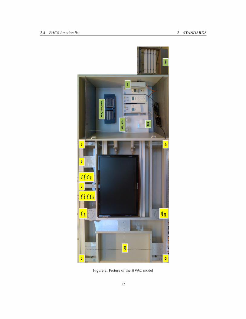
2.4 BACS function listOne of the main parts of the two mentioned standards is the BACS function list. In thissection, the suggested way of producing the BACS function list is followed to createthe function list of the HVAC model. The model is used to teach the students in a prac-tical way the most important topics of building automation and control systems. Themodel itself contains only field devices and no automation equipments. It is then thetask of the students to engineer the automation equipment of different manufacturers
7

2.4 BACS function list 2 STANDARDS
and learn how to handle their specific tools for engineering and programming. There-fore the BACS function list is rather small, because it only contains some I/O functions.
The model is divided into two parts. Within the Direct Digital Control (DDC) the aircan be prepared. The fresh air comes into the system and can be changed to the condi-tions needed within the room. The air comes out of the room into the DCC and can beused again in a loop or be transported out of the system.
In the DDC, there are 7 temperature sensors (B01 - B07), to check the temperature indifferent places within the system. First, there is a sensor for the outside temperature(B01), then there are two sensors to get the temperature for the feed lines of the heating(B07) and air conditioning system (B05). The temperature of the supply air is alsorecorded after the heating system (B02) and as a last point before the air comes into theroom (B03). The temperature of the discharging air is checked when it comes out ofthe room (B04) and before it leaves the system (B06).As it was always difficult to connect the temperature sensors with DDCs of differentmanufactures, these sensors are now connected over a BTR Module using LonWorks.
The temperature sensors B03 and B04 are combined temperature and humidity sen-sors. These sensors are located directly before the entrance to the room and when theair comes out of the room.The humidity value is a 0 – 10V signal which can directly be used from the model.
To control the amount of fresh and looping air there are 3 damper actuators withinthe system. They are merged together to one 0 – 10V control signal (M01) within themodel.
Concerning ventilation, the DDC provides different data points: two fans and their cor-responding speed are controlled via a 0 – 10V signal (M04, M05). In addition, thereare two separate switches to turn them on/off. There are failure notifications for theseventilators (S02 and S03), which simulate an error condition by the help of a switchcontrolling a 24V signal.
To change the condition of the air, there are 3 components used. First there is the heat-ing system, which is a small hot water boiler. From here the water is transferred with apump (M03) into a heat exchanger and the room.For controlling this part, there is a switch to turn on/off the hot water boiler (A06) anda 0 – 10V signal to change the speed of the pump. As the pump is working with 12V,this 0 – 10V signal is used to control a PWM module which then gives the 12V to thepump. The heating system has also a simulated disable notification for frost protection
8

2.4 BACS function list 2 STANDARDS
(S01), which is only a 24V signal and is not connected directly.The air conditioning works with the same configuration as the heating. A pump (M02)is used to bring the cold water into a heat exchanger and the room.It is also controlled by a switch (A03) and the same configuration for the pump.A humidifier is connected with the supply air and can be controlled with a switch (A04)to be turned on/off.
The second part is the single room. Here some sensors and actuators are used to achievecomfortable conditions within the room. There is a 4 pipe fan coil system with separatepumps for heating (M06) and cooling (M07), and a shared 3 step ventilator (M08).To control the pumps again the configuration 0 – 10V and 12V PWM signals are used.The 3 steps of the ventilator are connected over relays which can be controlled by dif-ferent 24V signals. There are 3 fake disable notifications for on-site notification (S04),window contact (S06) and condensate protection (S05) which are connected to a 24Vsignal.
In the room there exists a second rather slow heating system (A14), which can be con-trolled with a 0 – 10V signal that is normally connected to the DDC.
Within the room there are two separate lights (A12 and A13) and a shutter (A11). Theyare connected via relays and need 24V to change the condition.
As a last part there is a room controller which is used for a combined temperature andhumidity sensor. Here normally only the humidity sensor (B08), which is a 0 – 10Vsignal, is used, because if the room later is controlled with components of differentmanufacturers there is always an own room controller with a specific temperature sen-sor.
9

2.4 BACS function list 2 STANDARDS
DDC
Datapoint Short code Datatype PLC Value
Temperature outside
Temperature supply air
Temperature supply air
Temperature discharging air
Temperature feed line cold
Temperature discharging air
Temperature feed line hot
Humidity supply air
Humidity discharging air
Damper actuators
Ventilator supply air
Ventilator discharging air
Ventilator disable notification supply air
Ventilator disable notification discharging air
Heating system
Disable notification frost protection
Air condition system
Humidifier
ROOM
Datapoint
FANCoil - Pump heating system
FANCoil - Pump air condition system
FANCoil - Ventilator
Disable notification onside
Disable notification window contact
Disable notification condensate protection
Heat source room slow
Light room 1
Light room 2
Sun blind room
Humidity room
B01 AI LON
B02 AI LON
B03 AI LON
B04 AI LON
B05 AI LON
B06 AI LON
B07 AI LON
B03 AI 0-10 V
B04 AI 0-10 V
M01 AO 0-10 V
M04 AO 0-10 V
M04 DO 1/0
M05 AO 0-10 V
M05 DO 1/0
S02 DI 1/0
S03 DI 1/0
M03 AO 0-10 V
A06 DO 1/0
S01 DI 1/0
M02 AO 0-10 V
A03 DO 1/0
A04 DO 1/0
Short code Datatype PLC Value
M06 AO 0-10 V
M07 AO 0-10 V
M08 DO 1/0
S04 DI 1/0
S06 DI 1/0
S05 DI 1/0
A14 A0 0-10 V
A12 DO 1/0
A13 DO 1/0
A11 DO 1/0
B08 AI 0-10 V
Table 1: List of datapoints
10

2.4 BACS function list 2 STANDARDS
Figure 1: Plant schematic of the HVAC model
11
2.4 BACS function list 2 STANDARDS
Figure 2: Picture of the HVAC model
12

2.4 BACS function list 2 STANDARDS
Bui
ldin
g A
utom
atio
nB
uild
ing
Aut
omat
ion
Bui
ldin
g A
utom
atio
n1)
Ste
ady
Sta
te O
utpu
t: e.
g. 0
,I,II=
2 B
OS
tead
y S
tate
Out
put:
e.g.
0,I,
II=2
BO
Ste
ady
Sta
te O
utpu
t: e.
g. 0
,I,II=
2 B
OS
tead
y S
tate
Out
put:
e.g.
0,I,
II=2
BO
Ste
ady
Sta
te O
utpu
t: e.
g. 0
,I,II=
2 B
OS
tead
y S
tate
Out
put:
e.g.
0,I,
II=2
BO
Ste
ady
Sta
te O
utpu
t: e.
g. 0
,I,II=
2 B
OS
tead
y S
tate
Out
put:
e.g.
0,I,
II=2
BO
3)S
hare
d I/O
dat
a po
ints
from
fore
ign
syst
ems
Sha
red
I/O d
ata
poin
ts fr
om fo
reig
n sy
stem
sS
hare
d I/O
dat
a po
ints
from
fore
ign
syst
ems
Sha
red
I/O d
ata
poin
ts fr
om fo
reig
n sy
stem
sS
hare
d I/O
dat
a po
ints
from
fore
ign
syst
ems
Sha
red
I/O d
ata
poin
ts fr
om fo
reig
n sy
stem
sS
hare
d I/O
dat
a po
ints
from
fore
ign
syst
ems
Sha
red
I/O d
ata
poin
ts fr
om fo
reig
n sy
stem
sS
hare
d I/O
dat
a po
ints
from
fore
ign
syst
ems
Sha
red
I/O d
ata
poin
ts fr
om fo
reig
n sy
stem
s6)
For c
oolin
g/he
atin
g us
e 2x
On/
Off
outp
utFo
r coo
ling/
heat
ing
use
2x O
n/O
ff ou
tput
For c
oolin
g/he
atin
g us
e 2x
On/
Off
outp
utFo
r coo
ling/
heat
ing
use
2x O
n/O
ff ou
tput
For c
oolin
g/he
atin
g us
e 2x
On/
Off
outp
utFo
r coo
ling/
heat
ing
use
2x O
n/O
ff ou
tput
For c
oolin
g/he
atin
g us
e 2x
On/
Off
outp
utFo
r coo
ling/
heat
ing
use
2x O
n/O
ff ou
tput
For c
oolin
g/he
atin
g us
e 2x
On/
Off
outp
ut
and
Con
trol
Sys
tem
and
Con
trol
Sys
tem
Pul
sed
Out
put:
e.g.
0,I,
II=3
BO
Pul
sed
Out
put:
e.g.
0,I,
II=3
BO
Pul
sed
Out
put:
e.g.
0,I,
II=3
BO
Pul
sed
Out
put:
e.g.
0,I,
II=3
BO
Pul
sed
Out
put:
e.g.
0,I,
II=3
BO
Pul
sed
Out
put:
e.g.
0,I,
II=3
BO
Pul
sed
Out
put:
e.g.
0,I,
II=3
BO
for i
nter
oper
able
func
tions
, inc
l. vi
a D
IUfo
r int
erop
erab
le fu
nctio
ns, i
ncl.
via
DIU
for i
nter
oper
able
func
tions
, inc
l. vi
a D
IUfo
r int
erop
erab
le fu
nctio
ns, i
ncl.
via
DIU
for i
nter
oper
able
func
tions
, inc
l. vi
a D
IUfo
r int
erop
erab
le fu
nctio
ns, i
ncl.
via
DIU
for i
nter
oper
able
func
tions
, inc
l. vi
a D
IUfo
r int
erop
erab
le fu
nctio
ns, i
ncl.
via
DIU
for i
nter
oper
able
func
tions
, inc
l. vi
a D
IU7)
Per
inpu
t poi
nt a
ddre
ssP
er in
put p
oint
add
ress
Per
inpu
t poi
nt a
ddre
ssP
er in
put p
oint
add
ress
Per
inpu
t poi
nt a
ddre
ssP
er in
put p
oint
add
ress
BA
CS-
poin
ts li
stB
AC
S-po
ints
list
Pos
ition
ing
Out
put:
e.g.
Clo
se-0
-Ope
n =
2 B
OP
ositi
onin
g O
utpu
t: e.
g. C
lose
-0-O
pen
= 2
BO
Pos
ition
ing
Out
put:
e.g.
Clo
se-0
-Ope
n =
2 B
OP
ositi
onin
g O
utpu
t: e.
g. C
lose
-0-O
pen
= 2
BO
Pos
ition
ing
Out
put:
e.g.
Clo
se-0
-Ope
n =
2 B
OP
ositi
onin
g O
utpu
t: e.
g. C
lose
-0-O
pen
= 2
BO
Pos
ition
ing
Out
put:
e.g.
Clo
se-0
-Ope
n =
2 B
OP
ositi
onin
g O
utpu
t: e.
g. C
lose
-0-O
pen
= 2
BO
Pos
ition
ing
Out
put:
e.g.
Clo
se-0
-Ope
n =
2 B
OP
ositi
onin
g O
utpu
t: e.
g. C
lose
-0-O
pen
= 2
BO
4)P
er in
put p
oint
add
ress
for c
olle
cted
,P
er in
put p
oint
add
ress
for c
olle
cted
,P
er in
put p
oint
add
ress
for c
olle
cted
,P
er in
put p
oint
add
ress
for c
olle
cted
,P
er in
put p
oint
add
ress
for c
olle
cted
,P
er in
put p
oint
add
ress
for c
olle
cted
,P
er in
put p
oint
add
ress
for c
olle
cted
,P
er in
put p
oint
add
ress
for c
olle
cted
,P
er in
put p
oint
add
ress
for c
olle
cted
,8)
e.g.
Dev
ice,
sch
edul
e, li
fesa
fety
, loo
p, fi
le (s
ee E
N IS
O 1
6484
-5)
e.g.
Dev
ice,
sch
edul
e, li
fesa
fety
, loo
p, fi
le (s
ee E
N IS
O 1
6484
-5)
e.g.
Dev
ice,
sch
edul
e, li
fesa
fety
, loo
p, fi
le (s
ee E
N IS
O 1
6484
-5)
e.g.
Dev
ice,
sch
edul
e, li
fesa
fety
, loo
p, fi
le (s
ee E
N IS
O 1
6484
-5)
e.g.
Dev
ice,
sch
edul
e, li
fesa
fety
, loo
p, fi
le (s
ee E
N IS
O 1
6484
-5)
e.g.
Dev
ice,
sch
edul
e, li
fesa
fety
, loo
p, fi
le (s
ee E
N IS
O 1
6484
-5)
e.g.
Dev
ice,
sch
edul
e, li
fesa
fety
, loo
p, fi
le (s
ee E
N IS
O 1
6484
-5)
e.g.
Dev
ice,
sch
edul
e, li
fesa
fety
, loo
p, fi
le (s
ee E
N IS
O 1
6484
-5)
e.g.
Dev
ice,
sch
edul
e, li
fesa
fety
, loo
p, fi
le (s
ee E
N IS
O 1
6484
-5)
e.g.
Dev
ice,
sch
edul
e, li
fesa
fety
, loo
p, fi
le (s
ee E
N IS
O 1
6484
-5)
e.g.
Dev
ice,
sch
edul
e, li
fesa
fety
, loo
p, fi
le (s
ee E
N IS
O 1
6484
-5)
e.g.
Dev
ice,
sch
edul
e, li
fesa
fety
, loo
p, fi
le (s
ee E
N IS
O 1
6484
-5)
e.g.
Dev
ice,
sch
edul
e, li
fesa
fety
, loo
p, fi
le (s
ee E
N IS
O 1
6484
-5)
e.g.
Dev
ice,
sch
edul
e, li
fesa
fety
, loo
p, fi
le (s
ee E
N IS
O 1
6484
-5)
Pul
se W
idth
Mod
ulat
ion
Out
put =
1 B
OP
ulse
Wid
th M
odul
atio
n O
utpu
t = 1
BO
Pul
se W
idth
Mod
ulat
ion
Out
put =
1 B
OP
ulse
Wid
th M
odul
atio
n O
utpu
t = 1
BO
Pul
se W
idth
Mod
ulat
ion
Out
put =
1 B
OP
ulse
Wid
th M
odul
atio
n O
utpu
t = 1
BO
Pul
se W
idth
Mod
ulat
ion
Out
put =
1 B
OP
ulse
Wid
th M
odul
atio
n O
utpu
t = 1
BO
Pul
se W
idth
Mod
ulat
ion
Out
put =
1 B
Ode
laye
d or
sup
pres
sed
info
rmat
ion
dela
yed
or s
uppr
esse
d in
form
atio
nde
laye
d or
sup
pres
sed
info
rmat
ion
dela
yed
or s
uppr
esse
d in
form
atio
nde
laye
d or
sup
pres
sed
info
rmat
ion
dela
yed
or s
uppr
esse
d in
form
atio
nde
laye
d or
sup
pres
sed
info
rmat
ion
dela
yed
or s
uppr
esse
d in
form
atio
n9)
If re
quire
d, in
dica
te w
heth
er a
pplie
s to
clie
nt „A
“ or s
erve
r „B
“If
requ
ired,
indi
cate
whe
ther
app
lies
to c
lient
„A“ o
r ser
ver „
B“
If re
quire
d, in
dica
te w
heth
er a
pplie
s to
clie
nt „A
“ or s
erve
r „B
“If
requ
ired,
indi
cate
whe
ther
app
lies
to c
lient
„A“ o
r ser
ver „
B“
If re
quire
d, in
dica
te w
heth
er a
pplie
s to
clie
nt „A
“ or s
erve
r „B
“If
requ
ired,
indi
cate
whe
ther
app
lies
to c
lient
„A“ o
r ser
ver „
B“
If re
quire
d, in
dica
te w
heth
er a
pplie
s to
clie
nt „A
“ or s
erve
r „B
“If
requ
ired,
indi
cate
whe
ther
app
lies
to c
lient
„A“ o
r ser
ver „
B“
If re
quire
d, in
dica
te w
heth
er a
pplie
s to
clie
nt „A
“ or s
erve
r „B
“If
requ
ired,
indi
cate
whe
ther
app
lies
to c
lient
„A“ o
r ser
ver „
B“
If re
quire
d, in
dica
te w
heth
er a
pplie
s to
clie
nt „A
“ or s
erve
r „B
“If
requ
ired,
indi
cate
whe
ther
app
lies
to c
lient
„A“ o
r ser
ver „
B“
If re
quire
d, in
dica
te w
heth
er a
pplie
s to
clie
nt „A
“ or s
erve
r „B
“If
requ
ired,
indi
cate
whe
ther
app
lies
to c
lient
„A“ o
r ser
ver „
B“
2)A
ctiv
e or
pas
sive
Act
ive
or p
assi
veA
ctiv
e or
pas
sive
Act
ive
or p
assi
ve5)
Per
out
put p
oint
add
ress
Per
out
put p
oint
add
ress
Per
out
put p
oint
add
ress
Per
out
put p
oint
add
ress
Per
out
put p
oint
add
ress
Per
out
put p
oint
add
ress
Trad
e:I/O
Fun
ctio
nsI/O
Fun
ctio
nsI/O
Fun
ctio
nsI/O
Fun
ctio
nsI/O
Fun
ctio
nsI/O
Fun
ctio
nsI/O
Fun
ctio
nsI/O
Fun
ctio
nsI/O
Fun
ctio
nsI/O
Fun
ctio
nsPr
oces
sing
Fun
ctio
nsPr
oces
sing
Fun
ctio
nsPr
oces
sing
Fun
ctio
nsPr
oces
sing
Fun
ctio
nsPr
oces
sing
Fun
ctio
nsPr
oces
sing
Fun
ctio
nsPr
oces
sing
Fun
ctio
nsPr
oces
sing
Fun
ctio
nsPr
oces
sing
Fun
ctio
nsPr
oces
sing
Fun
ctio
nsPr
oces
sing
Fun
ctio
nsPr
oces
sing
Fun
ctio
nsPr
oces
sing
Fun
ctio
nsPr
oces
sing
Fun
ctio
nsPr
oces
sing
Fun
ctio
nsPr
oces
sing
Fun
ctio
nsPr
oces
sing
Fun
ctio
nsPr
oces
sing
Fun
ctio
nsPr
oces
sing
Fun
ctio
nsPr
oces
sing
Fun
ctio
nsPr
oces
sing
Fun
ctio
nsPr
oces
sing
Fun
ctio
nsPr
oces
sing
Fun
ctio
nsPr
oces
sing
Fun
ctio
nsPr
oces
sing
Fun
ctio
nsPr
oces
sing
Fun
ctio
nsPr
oces
sing
Fun
ctio
nsPr
oces
sing
Fun
ctio
nsPr
oces
sing
Fun
ctio
nsPr
oces
sing
Fun
ctio
nsPr
oces
sing
Fun
ctio
nsPr
oces
sing
Fun
ctio
nsM
anag
emen
tM
anag
emen
tM
anag
emen
tM
anag
emen
tO
pera
tor
Ope
rato
rO
pera
tor
Ope
rato
rTr
ade:
Phy
sica
lP
hysi
cal
Phy
sica
lP
hysi
cal
Phy
sica
lC
omm
unic
atio
n 3)
9)
Com
mun
icat
ion
3) 9
)C
omm
unic
atio
n 3)
9)
Com
mun
icat
ion
3) 9
)C
omm
unic
atio
n 3)
9)
Mon
itorin
gM
onito
ring
Mon
itorin
gM
onito
ring
Mon
itorin
gM
onito
ring
Inte
rlock
sIn
terlo
cks
Inte
rlock
sIn
terlo
cks
Inte
rlock
sC
lose
d Lo
op C
ontro
lC
lose
d Lo
op C
ontro
lC
lose
d Lo
op C
ontro
lC
lose
d Lo
op C
ontro
lC
lose
d Lo
op C
ontro
lC
lose
d Lo
op C
ontro
lC
lose
d Lo
op C
ontro
lC
lose
d Lo
op C
ontro
lC
alcu
latio
n/O
ptim
isat
ion
Cal
cula
tion/
Opt
imis
atio
nC
alcu
latio
n/O
ptim
isat
ion
Cal
cula
tion/
Opt
imis
atio
nC
alcu
latio
n/O
ptim
isat
ion
Cal
cula
tion/
Opt
imis
atio
nC
alcu
latio
n/O
ptim
isat
ion
Cal
cula
tion/
Opt
imis
atio
nC
alcu
latio
n/O
ptim
isat
ion
Cal
cula
tion/
Opt
imis
atio
nC
alcu
latio
n/O
ptim
isat
ion
Cal
cula
tion/
Opt
imis
atio
nC
alcu
latio
n/O
ptim
isat
ion
Func
tions
Func
tions
Func
tions
Func
tions
Func
tions
Func
tions
Func
tions
Func
tions
Plan
t:
Des
crip
tion
Sec
tion
No.
1111122222
33333344444
555555556666666666666
77778888
99D
atap
oint
/Obj
ect
Dat
apoi
nt/O
bjec
tC
olum
n N
o.1
23
45
12
34
51
23
45
61
23
45
12
34
56
78
12
34
56
78
910
1112
131
23
41
23
4R
emar
ks
1Te
mpe
ratu
re d
isch
argi
ng a
irTe
mpe
ratu
re d
isch
argi
ng a
ir1
2.5
Tem
p on
LO
N
2Te
mpe
ratu
re o
utsi
deTe
mpe
ratu
re o
utsi
de1
2.5
Tem
p on
LO
N
3Te
mpe
ratu
re s
uppl
y ai
rTe
mpe
ratu
re s
uppl
y ai
r1
2.5
Tem
p on
LO
N
4Te
mpe
ratu
re/H
umid
ity s
uppl
y ai
rTe
mpe
ratu
re/H
umid
ity s
uppl
y ai
r1
12.
5 Te
mp
on L
ON
5Te
mpe
ratu
re/H
umid
ity d
isch
argi
ng a
irTe
mpe
ratu
re/H
umid
ity d
isch
argi
ng a
ir1
12.
5 Te
mp
on L
ON
6D
ampe
r act
uato
rs1
1.2
Dam
per a
ctua
tors
mer
ged
to o
ne o
utpu
t
7V
entil
atio
n su
pply
air
Ven
tilat
ion
supp
ly a
ir1
11
8V
entil
atio
n di
scha
rgin
g ai
rV
entil
atio
n di
scha
rgin
g ai
r1
11
9H
eatin
g sy
stem
11
11
2.5
Tem
p on
LO
N
10A
ir co
nditi
on s
yste
mA
ir co
nditi
on s
yste
m1
11
2.5
Tem
p on
LO
N
11H
umid
ifier
1
12FA
NC
oil
32
3
13H
eat s
ourc
e ro
om fa
stH
eat s
ourc
e ro
om fa
st1
14H
eat s
oruc
e ro
om s
low
Hea
t sor
uce
room
slo
w1
15Li
ght r
oom
21.
1 tw
o La
mps
16S
un b
lind
room
2
17Te
mpe
ratu
r roo
m1
18H
umid
ity ro
om1
Tota
lsTo
tals
Tota
ls12
96
04
00
00
70
00
00
00
00
00
00
00
00
00
00
00
00
00
00
00
00
00
00
00
038
Issue
Date
Aut
hor
App
rove
dA
ppro
ved
App
rove
dC
ompa
nyC
ompa
nyC
ompa
nyPr
ojec
tPr
ojec
tPr
ojec
tLo
catio
n of
Con
trols
(ME
R):
Loca
tion
of C
ontro
ls (M
ER
):Lo
catio
n of
Con
trols
(ME
R):
Loca
tion
of C
ontro
ls (M
ER
):Lo
catio
n of
Con
trols
(ME
R):
Loca
tion
of C
ontro
ls (M
ER
):Lo
catio
n of
Con
trols
(ME
R):
File
:Fi
le:
Rev
. 1 R
ev. 2
Con
trol.
Dia
g. N
o.:
Con
trol.
Dia
g. N
o.:
Con
trol.
Dia
g. N
o.:
Con
trol.
Dia
g. N
o.:
Con
trol.
Dia
g. N
o.:
Con
trol.
Dia
g. N
o.:
Con
trol.
Dia
g. N
o.:
Con
trol.
Dia
g. N
o.:
Con
trol.
Dia
g. N
o.:
Con
trol.
Dia
g. N
o.:
Con
trol.
Dia
g. N
o.:
Con
trol.
Dia
g. N
o.:
Con
trol.
Dia
g. N
o.:
Con
trol.
Dia
g. N
o.:
Pag
e N
o.P
age
No.
Rev
. 3ofof
Row No.
Binary Output Switching/Positioning 1)
Analog Output Positioning
Binary Input, State
Binary Input, Counting
Analog Input 2)
Output Switching
Output Positioning/Setpoint
Input Event Messaging
Input Totalized Value
Input Measuring
Fixed Limit
Sliding Limit
Run Time Totalization
Event Counting
Command Executing Check
Message Processing 4)
Plant Control
Motor Control
Switchover 5)
Step Control 5)
Safety/Frost Protection Control
P Control
PI/PID Control
Sliding-/Curve Setpoint
Proportional Output Stage
Proportional to On/Off Conversion 6)
Proportional to Pulse Width Modulation
Setpoint/output Limitation
Switchover of Parameters
h, x Directed Control Strategy
Arithmetic Calculation 7)
Event Switching
Time Schedule
Optimum Start/Stop
Duty Cycling
Night Cooling
RoomTemperature Limitation
Energy Recovery
Backup Power Operation
Mains Recovery Program
Peak Load Limitation
Energy Tariff Depend. Switching
I7O Communication object types
Complex object types 8) 9)
Event Storage
Historical Data Base
Graphic/Static Plant Schematic
Dynamic Display
Event Instruction Text
Remote Messaging
Figure 3: BACS function list of model
13

3 SAIA-BURGESS
3 Saia-Burgess3.1 IntroductionSaia-Burgess is a manufacturer of electronic components, devices and systems for con-trol engineering, with special strength in developing and servicing niche markets. Theywork together with system integrators, OEMs and brand label customers. The compa-nies headquarters is in Murten (CH), but there is also an office in Salzburg (A).For the practical part of this thesis, Saia-Burgess products are used to control the HVACmodel from the Distributed Automation Systems Lab. The programmable logic con-troller PCD2.M170 [7] is used as DDC and the single room is controlled by a roomcontroller PCD7.L601 [8, 9]. Both products are configured with the PG5 2.0 softwareform Saia-Burgess. [6]
The DDC PCD2.M170 is the main part of this installation. The unit is freely pro-grammable and configurable and offers next to some on board interfaces for RS-232and RS-485 communication, 8 module slots for add-on modules. Using different add-on modules make it easier to configure the DDC for individual needs. In this case,the DDC is equipped with 4 modules and enhanced with modules for LonWorks andEthernet.
14

3.1 Introduction 3 SAIA-BURGESS
Figure 4: Configuration of the PCD2.M170 with add-on modules
The PCD2.A220, a digital out module contains 6 relays with normally-open contactsand is used to control the enable-switch for both supply air and discharging air ventila-tion, for the HVAC system and for the humidifier.
The PCD2.E610 is a digital input module and is used to determine the disable notifi-cation from the supply air and discharging air ventilation, the frost protection and thecondensate. In the used HVAC model, these data points are not really connected tothe mentioned equipment. They are simulated and can be activated by a switch on theHVAC model.
An analogue out module PCD2.W605 is used for all positioning tasks: Controlling thespeed of the ventilators for supply air and discharging air, positioning of the dampersand controlling the circulatory speed for the air conditioning and heating pumps.
The last module PCD2.W525 is a combined analogue output and input module whichis used for the heating of the single room and to get humidity values from the supplyair, the discharging air and the single room. On the last analogue input, a PT1000 tem-perature sensor is used to get the room temperature as an independent value.
For communication with LonWorks, Ethernet and RS485 the DDC is equipped withthree communication modules called PCD7.F800, PCD7.F655 and PCD7.F110. Thesetechnologies are used to include the temperature sensors from the HVAC model (LON),to connect the DDC with the Saia-Burgess room controller (RS-485) and the networkof the institute (Ethernet). The Ethernet connection is also used to program and config-ure the DDC with the PG5 software.
15
3.1 Introduction 3 SAIA-BURGESS
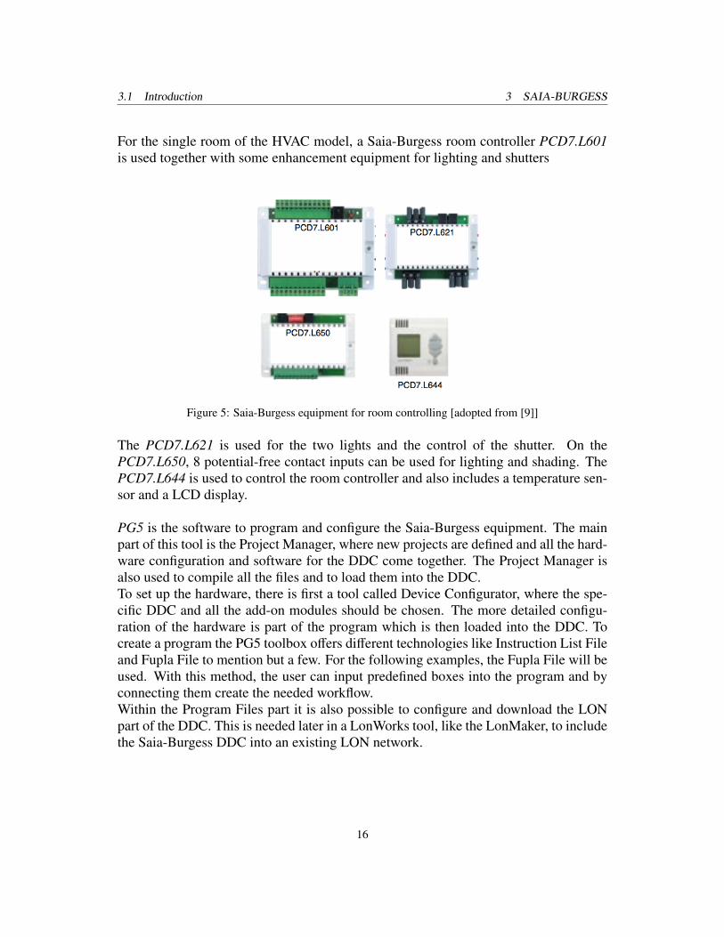
For the single room of the HVAC model, a Saia-Burgess room controller PCD7.L601is used together with some enhancement equipment for lighting and shutters
Figure 5: Saia-Burgess equipment for room controlling [adopted from [9]]
The PCD7.L621 is used for the two lights and the control of the shutter. On thePCD7.L650, 8 potential-free contact inputs can be used for lighting and shading. ThePCD7.L644 is used to control the room controller and also includes a temperature sen-sor and a LCD display.
PG5 is the software to program and configure the Saia-Burgess equipment. The mainpart of this tool is the Project Manager, where new projects are defined and all the hard-ware configuration and software for the DDC come together. The Project Manager isalso used to compile all the files and to load them into the DDC.To set up the hardware, there is first a tool called Device Configurator, where the spe-cific DDC and all the add-on modules should be chosen. The more detailed configu-ration of the hardware is part of the program which is then loaded into the DDC. Tocreate a program the PG5 toolbox offers different technologies like Instruction List Fileand Fupla File to mention but a few. For the following examples, the Fupla File will beused. With this method, the user can input predefined boxes into the program and byconnecting them create the needed workflow.Within the Program Files part it is also possible to configure and download the LONpart of the DDC. This is needed later in a LonWorks tool, like the LonMaker, to includethe Saia-Burgess DDC into an existing LON network.
16

3.2 Configuration 3 SAIA-BURGESS
PCD2.M170
switch on/off - digital outM04, M05, A03, A04
disable notification- digital inS01, S02, S03, S05
positioning - analog outM01, M02, M03, M04, M05
heating and humidity - analog out/in
A14, A15, B03, B04, B08, Pt1000
RS 485
room controller - FANCoilM06, M07, M08
room controller - switchA08, A12, A13
room controller - light and shadowA08, A12, A13
PCD7.L644
Figure 6: Configuration with Saia-Burgess products
3.2 ConfigurationTo be able to use all the data points available in the model, it is necessary to configurethem within the PG5 [10]. This happens in an own Fupla file and a LON file where alsothe analogue cards are configured. Special boxes for each analogue module have to beselected where it is possible to enter specific properties, like 0 – 10V.
17

3.2 Configuration 3 SAIA-BURGESS
Figure 7: Properties from module W525
18

3.2 Configuration 3 SAIA-BURGESS
Figure 8: Configuration
19

3.2 Configuration 3 SAIA-BURGESS
Figure 9: Configuration (cont.)
20

3.2 Configuration 3 SAIA-BURGESS
DDC
Datapoint model
Temperature outside
Temperature supply air
Temperature supply air
Temperature discharging air
Temperature feed line cold
Temperature discharging air
Temperature feed line hot
Humidity supply air
Humidity discharging air
Damper actuators
Ventilator supply air
Ventilator discharging air
Ventilator disable notification supply air
Ventilator disable notification discharging air
Heating system
Disable notification frost protection
Air condition system
Humidifier
ROOM
Datapoint model
FANCoil - Pump heating system
FANCoil - Pump air condition system
FANCoil - Ventilator
Disable notification onside
Disable notification window contact
Disable notification condensate protection
Heat source room slow
Light room 1
Light room 2
Sun blind room
Humidity room
Additional Datapoints
Datapoint example
Error_W605
Error_W525
PT1000_Temp
Waerme_schnell
Raum_occupied
Raum_stell_Temp
Raum_akt_Temp
Raum_heizen
Raum_kühlen
Raum_heizsignal
Raum_Vent_Stufe
Raum_Error
Licht_Status_G0
Licht_Status_G1
Rollo_Status_G0_Ab
Rollo_Status_G0_Auf
Short code Datatype Datapoint example
B01 AI AU_BO1_Temp
B02 AI ZU_BO2_Temp
B03 AI ZU_BO3_Temp
B04 AI AB_B04_Temp
B05 AI K_B05_Temp
B06 AI AB_B06_Temp
B07 AI H_B07_Temp
B03 AI Feuchte_Zul
B04 AI Feuchte_Abl
MO1 AO StKlap
M04 AO StVenZul
MO4 DO FRQ_Vent_Zul
M05 AO StVenAbl
M05 DO FRQ_Vent_Abl
S02 DI Vent_Zul_Stoerung
S03 DI Vent_Abl_Stoerung
M03 AO StPumpHZul
A06 DO FRQ_Durchlauferhitzer
S01 DI Frostmelder
M02 AO StPumpKZul
A03 DO FRQ_Kälte
A04 DO FRQ_Befeuchter
Short code Datatype Datapoint example
M06 AO -
M07 AO -
M08 DO -
S04 DI -
S06 DI -
S05 DI Kondensatmelder
A14 A0 Waerme_langsam
A12 DO Licht_G0_Ein/Licht_G0_Aus
A13 DO Licht_G1_Ein/Licht_G0_Aus
A11 DO Rollo_Go_Auf/Rollo_Go_Ab
B08 AI Feuchte_RBG
ExplainationExplainationExplaination
Error Message from Module W605Error Message from Module W605Error Message from Module W605
Error Message from Module W525Error Message from Module W525Error Message from Module W525
PT1000 Temperature sensor to get one direct value from the environmentPT1000 Temperature sensor to get one direct value from the environmentPT1000 Temperature sensor to get one direct value from the environment
Datapoint A15 in model, but this actor is not available at the momentDatapoint A15 in model, but this actor is not available at the momentDatapoint A15 in model, but this actor is not available at the moment
Actual information of room controller configurationActual information of room controller configurationActual information of room controller configurationActual information of room controller configurationActual information of room controller configurationActual information of room controller configurationActual information of room controller configurationActual information of room controller configurationActual information of room controller configurationActual information of room controller configurationActual information of room controller configurationActual information of room controller configurationActual information of room controller configurationActual information of room controller configurationActual information of room controller configurationActual information of room controller configurationActual information of room controller configurationActual information of room controller configurationActual information of room controller configurationActual information of room controller configurationActual information of room controller configurationActual information of room controller configurationActual information of room controller configurationActual information of room controller configuration
Actual status of Light G0Actual status of Light G0Actual status of Light G0
Actual status of Light G1Actual status of Light G1Actual status of Light G1
Endpositon sun blind upEndpositon sun blind upEndpositon sun blind up
Endpositon sun blind downEndpositon sun blind downEndpositon sun blind down
Table 2: List of datapoints used in the configuration
21

3.2 Configuration 3 SAIA-BURGESS
Figure 10: LON configuration within the DDC
Figure 11: LON configuration within the DDC
22
3.3 Exercises 3 SAIA-BURGESS
3.3 Exercises3.3 Exercise 1Description
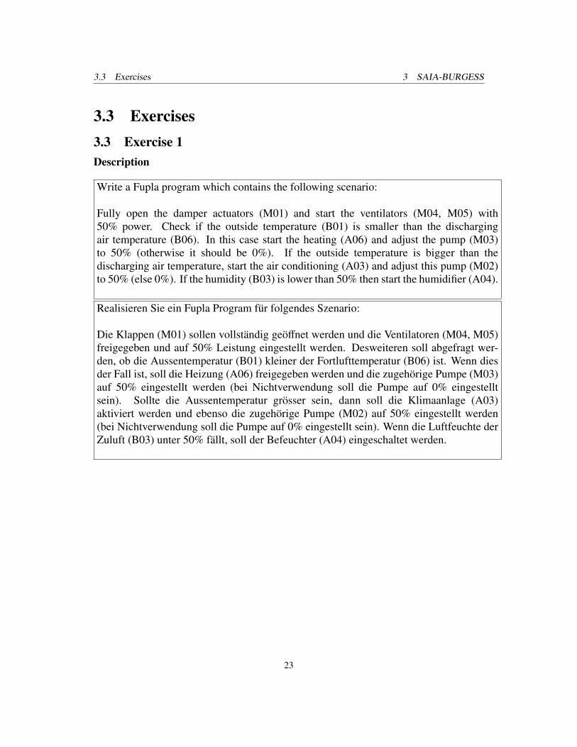
Write a Fupla program which contains the following scenario:
Fully open the damper actuators (M01) and start the ventilators (M04, M05) with50% power. Check if the outside temperature (B01) is smaller than the dischargingair temperature (B06). In this case start the heating (A06) and adjust the pump (M03)to 50% (otherwise it should be 0%). If the outside temperature is bigger than thedischarging air temperature, start the air conditioning (A03) and adjust this pump (M02)to 50% (else 0%). If the humidity (B03) is lower than 50% then start the humidifier (A04).
Realisieren Sie ein Fupla Program fur folgendes Szenario:
Die Klappen (M01) sollen vollstandig geoffnet werden und die Ventilatoren (M04, M05)freigegeben und auf 50% Leistung eingestellt werden. Desweiteren soll abgefragt wer-den, ob die Aussentemperatur (B01) kleiner der Fortlufttemperatur (B06) ist. Wenn diesder Fall ist, soll die Heizung (A06) freigegeben werden und die zugehorige Pumpe (M03)auf 50% eingestellt werden (bei Nichtverwendung soll die Pumpe auf 0% eingestelltsein). Sollte die Aussentemperatur grosser sein, dann soll die Klimaanlage (A03)aktiviert werden und ebenso die zugehorige Pumpe (M02) auf 50% eingestellt werden(bei Nichtverwendung soll die Pumpe auf 0% eingestellt sein). Wenn die Luftfeuchte derZuluft (B03) unter 50% fallt, soll der Befeuchter (A04) eingeschaltet werden.
23

3.3 Exercises 3 SAIA-BURGESS
Solution
Figure 12: Fupla program for example 1
24

3.3 Exercises 3 SAIA-BURGESS
Bui
ldin
g A
utom
atio
nB
uild
ing
Aut
omat
ion
Bui
ldin
g A
utom
atio
n1)
Ste
ady
Sta
te O
utpu
t: e.
g. 0
,I,II=
2 B
OS
tead
y S
tate
Out
put:
e.g.
0,I,
II=2
BO
Ste
ady
Sta
te O
utpu
t: e.
g. 0
,I,II=
2 B
OS
tead
y S
tate
Out
put:
e.g.
0,I,
II=2
BO
Ste
ady
Sta
te O
utpu
t: e.
g. 0
,I,II=
2 B
OS
tead
y S
tate
Out
put:
e.g.
0,I,
II=2
BO
Ste
ady
Sta
te O
utpu
t: e.
g. 0
,I,II=
2 B
OS
tead
y S
tate
Out
put:
e.g.
0,I,
II=2
BO
3)S
hare
d I/O
dat
a po
ints
from
fore
ign
syst
ems
Sha
red
I/O d
ata
poin
ts fr
om fo
reig
n sy
stem
sS
hare
d I/O
dat
a po
ints
from
fore
ign
syst
ems
Sha
red
I/O d
ata
poin
ts fr
om fo
reig
n sy
stem
sS
hare
d I/O
dat
a po
ints
from
fore
ign
syst
ems
Sha
red
I/O d
ata
poin
ts fr
om fo
reig
n sy
stem
sS
hare
d I/O
dat
a po
ints
from
fore
ign
syst
ems
Sha
red
I/O d
ata
poin
ts fr
om fo
reig
n sy
stem
sS
hare
d I/O
dat
a po
ints
from
fore
ign
syst
ems
Sha
red
I/O d
ata
poin
ts fr
om fo
reig
n sy
stem
s6)
For c
oolin
g/he
atin
g us
e 2x
On/
Off
outp
utFo
r coo
ling/
heat
ing
use
2x O
n/O
ff ou
tput
For c
oolin
g/he
atin
g us
e 2x
On/
Off
outp
utFo
r coo
ling/
heat
ing
use
2x O
n/O
ff ou
tput
For c
oolin
g/he
atin
g us
e 2x
On/
Off
outp
utFo
r coo
ling/
heat
ing
use
2x O
n/O
ff ou
tput
For c
oolin
g/he
atin
g us
e 2x
On/
Off
outp
utFo
r coo
ling/
heat
ing
use
2x O
n/O
ff ou
tput
For c
oolin
g/he
atin
g us
e 2x
On/
Off
outp
ut
and
Con
trol
Sys
tem
and
Con
trol
Sys
tem
Pul
sed
Out
put:
e.g.
0,I,
II=3
BO
Pul
sed
Out
put:
e.g.
0,I,
II=3
BO
Pul
sed
Out
put:
e.g.
0,I,
II=3
BO
Pul
sed
Out
put:
e.g.
0,I,
II=3
BO
Pul
sed
Out
put:
e.g.
0,I,
II=3
BO
Pul
sed
Out
put:
e.g.
0,I,
II=3
BO
Pul
sed
Out
put:
e.g.
0,I,
II=3
BO
for i
nter
oper
able
func
tions
, inc
l. vi
a D
IUfo
r int
erop
erab
le fu
nctio
ns, i
ncl.
via
DIU
for i
nter
oper
able
func
tions
, inc
l. vi
a D
IUfo
r int
erop
erab
le fu
nctio
ns, i
ncl.
via
DIU
for i
nter
oper
able
func
tions
, inc
l. vi
a D
IUfo
r int
erop
erab
le fu
nctio
ns, i
ncl.
via
DIU
for i
nter
oper
able
func
tions
, inc
l. vi
a D
IUfo
r int
erop
erab
le fu
nctio
ns, i
ncl.
via
DIU
for i
nter
oper
able
func
tions
, inc
l. vi
a D
IU7)
Per
inpu
t poi
nt a
ddre
ssP
er in
put p
oint
add
ress
Per
inpu
t poi
nt a
ddre
ssP
er in
put p
oint
add
ress
Per
inpu
t poi
nt a
ddre
ssP
er in
put p
oint
add
ress
BA
CS-
poin
ts li
stB
AC
S-po
ints
list
Pos
ition
ing
Out
put:
e.g.
Clo
se-0
-Ope
n =
2 B
OP
ositi
onin
g O
utpu
t: e.
g. C
lose
-0-O
pen
= 2
BO
Pos
ition
ing
Out
put:
e.g.
Clo
se-0
-Ope
n =
2 B
OP
ositi
onin
g O
utpu
t: e.
g. C
lose
-0-O
pen
= 2
BO
Pos
ition
ing
Out
put:
e.g.
Clo
se-0
-Ope
n =
2 B
OP
ositi
onin
g O
utpu
t: e.
g. C
lose
-0-O
pen
= 2
BO
Pos
ition
ing
Out
put:
e.g.
Clo
se-0
-Ope
n =
2 B
OP
ositi
onin
g O
utpu
t: e.
g. C
lose
-0-O
pen
= 2
BO
Pos
ition
ing
Out
put:
e.g.
Clo
se-0
-Ope
n =
2 B
OP
ositi
onin
g O
utpu
t: e.
g. C
lose
-0-O
pen
= 2
BO
4)P
er in
put p
oint
add
ress
for c
olle
cted
,P
er in
put p
oint
add
ress
for c
olle
cted
,P
er in
put p
oint
add
ress
for c
olle
cted
,P
er in
put p
oint
add
ress
for c
olle
cted
,P
er in
put p
oint
add
ress
for c
olle
cted
,P
er in
put p
oint
add
ress
for c
olle
cted
,P
er in
put p
oint
add
ress
for c
olle
cted
,P
er in
put p
oint
add
ress
for c
olle
cted
,P
er in
put p
oint
add
ress
for c
olle
cted
,8)
e.g.
Dev
ice,
sch
edul
e, li
fesa
fety
, loo
p, fi
le (s
ee E
N IS
O 1
6484
-5)
e.g.
Dev
ice,
sch
edul
e, li
fesa
fety
, loo
p, fi
le (s
ee E
N IS
O 1
6484
-5)
e.g.
Dev
ice,
sch
edul
e, li
fesa
fety
, loo
p, fi
le (s
ee E
N IS
O 1
6484
-5)
e.g.
Dev
ice,
sch
edul
e, li
fesa
fety
, loo
p, fi
le (s
ee E
N IS
O 1
6484
-5)
e.g.
Dev
ice,
sch
edul
e, li
fesa
fety
, loo
p, fi
le (s
ee E
N IS
O 1
6484
-5)
e.g.
Dev
ice,
sch
edul
e, li
fesa
fety
, loo
p, fi
le (s
ee E
N IS
O 1
6484
-5)
e.g.
Dev
ice,
sch
edul
e, li
fesa
fety
, loo
p, fi
le (s
ee E
N IS
O 1
6484
-5)
e.g.
Dev
ice,
sch
edul
e, li
fesa
fety
, loo
p, fi
le (s
ee E
N IS
O 1
6484
-5)
e.g.
Dev
ice,
sch
edul
e, li
fesa
fety
, loo
p, fi
le (s
ee E
N IS
O 1
6484
-5)
e.g.
Dev
ice,
sch
edul
e, li
fesa
fety
, loo
p, fi
le (s
ee E
N IS
O 1
6484
-5)
e.g.
Dev
ice,
sch
edul
e, li
fesa
fety
, loo
p, fi
le (s
ee E
N IS
O 1
6484
-5)
e.g.
Dev
ice,
sch
edul
e, li
fesa
fety
, loo
p, fi
le (s
ee E
N IS
O 1
6484
-5)
e.g.
Dev
ice,
sch
edul
e, li
fesa
fety
, loo
p, fi
le (s
ee E
N IS
O 1
6484
-5)
e.g.
Dev
ice,
sch
edul
e, li
fesa
fety
, loo
p, fi
le (s
ee E
N IS
O 1
6484
-5)
Pul
se W
idth
Mod
ulat
ion
Out
put =
1 B
OP
ulse
Wid
th M
odul
atio
n O
utpu
t = 1
BO
Pul
se W
idth
Mod
ulat
ion
Out
put =
1 B
OP
ulse
Wid
th M
odul
atio
n O
utpu
t = 1
BO
Pul
se W
idth
Mod
ulat
ion
Out
put =
1 B
OP
ulse
Wid
th M
odul
atio
n O
utpu
t = 1
BO
Pul
se W
idth
Mod
ulat
ion
Out
put =
1 B
OP
ulse
Wid
th M
odul
atio
n O
utpu
t = 1
BO
Pul
se W
idth
Mod
ulat
ion
Out
put =
1 B
Ode
laye
d or
sup
pres
sed
info
rmat
ion
dela
yed
or s
uppr
esse
d in
form
atio
nde
laye
d or
sup
pres
sed
info
rmat
ion
dela
yed
or s
uppr
esse
d in
form
atio
nde
laye
d or
sup
pres
sed
info
rmat
ion
dela
yed
or s
uppr
esse
d in
form
atio
nde
laye
d or
sup
pres
sed
info
rmat
ion
dela
yed
or s
uppr
esse
d in
form
atio
n9)
If re
quire
d, in
dica
te w
heth
er a
pplie
s to
clie
nt „A
“ or s
erve
r „B
“If
requ
ired,
indi
cate
whe
ther
app
lies
to c
lient
„A“ o
r ser
ver „
B“
If re
quire
d, in
dica
te w
heth
er a
pplie
s to
clie
nt „A
“ or s
erve
r „B
“If
requ
ired,
indi
cate
whe
ther
app
lies
to c
lient
„A“ o
r ser
ver „
B“
If re
quire
d, in
dica
te w
heth
er a
pplie
s to
clie
nt „A
“ or s
erve
r „B
“If
requ
ired,
indi
cate
whe
ther
app
lies
to c
lient
„A“ o
r ser
ver „
B“
If re
quire
d, in
dica
te w
heth
er a
pplie
s to
clie
nt „A
“ or s
erve
r „B
“If
requ
ired,
indi
cate
whe
ther
app
lies
to c
lient
„A“ o
r ser
ver „
B“
If re
quire
d, in
dica
te w
heth
er a
pplie
s to
clie
nt „A
“ or s
erve
r „B
“If
requ
ired,
indi
cate
whe
ther
app
lies
to c
lient
„A“ o
r ser
ver „
B“
If re
quire
d, in
dica
te w
heth
er a
pplie
s to
clie
nt „A
“ or s
erve
r „B
“If
requ
ired,
indi
cate
whe
ther
app
lies
to c
lient
„A“ o
r ser
ver „
B“
If re
quire
d, in
dica
te w
heth
er a
pplie
s to
clie
nt „A
“ or s
erve
r „B
“If
requ
ired,
indi
cate
whe
ther
app
lies
to c
lient
„A“ o
r ser
ver „
B“
2)A
ctiv
e or
pas
sive
Act
ive
or p
assi
veA
ctiv
e or
pas
sive
Act
ive
or p
assi
ve5)
Per
out
put p
oint
add
ress
Per
out
put p
oint
add
ress
Per
out
put p
oint
add
ress
Per
out
put p
oint
add
ress
Per
out
put p
oint
add
ress
Per
out
put p
oint
add
ress
Trad
e:I/O
Fun
ctio
nsI/O
Fun
ctio
nsI/O
Fun
ctio
nsI/O
Fun
ctio
nsI/O
Fun
ctio
nsI/O
Fun
ctio
nsI/O
Fun
ctio
nsI/O
Fun
ctio
nsI/O
Fun
ctio
nsI/O
Fun
ctio
nsPr
oces
sing
Fun
ctio
nsPr
oces
sing
Fun
ctio
nsPr
oces
sing
Fun
ctio
nsPr
oces
sing
Fun
ctio
nsPr
oces
sing
Fun
ctio
nsPr
oces
sing
Fun
ctio
nsPr
oces
sing
Fun
ctio
nsPr
oces
sing
Fun
ctio
nsPr
oces
sing
Fun
ctio
nsPr
oces
sing
Fun
ctio
nsPr
oces
sing
Fun
ctio
nsPr
oces
sing
Fun
ctio
nsPr
oces
sing
Fun
ctio
nsPr
oces
sing
Fun
ctio
nsPr
oces
sing
Fun
ctio
nsPr
oces
sing
Fun
ctio
nsPr
oces
sing
Fun
ctio
nsPr
oces
sing
Fun
ctio
nsPr
oces
sing
Fun
ctio
nsPr
oces
sing
Fun
ctio
nsPr
oces
sing
Fun
ctio
nsPr
oces
sing
Fun
ctio
nsPr
oces
sing
Fun
ctio
nsPr
oces
sing
Fun
ctio
nsPr
oces
sing
Fun
ctio
nsPr
oces
sing
Fun
ctio
nsPr
oces
sing
Fun
ctio
nsPr
oces
sing
Fun
ctio
nsPr
oces
sing
Fun
ctio
nsPr
oces
sing
Fun
ctio
nsPr
oces
sing
Fun
ctio
nsPr
oces
sing
Fun
ctio
nsM
anag
emen
tM
anag
emen
tM
anag
emen
tM
anag
emen
tO
pera
tor
Ope
rato
rO
pera
tor
Ope
rato
rTr
ade:
Phy
sica
lP
hysi
cal
Phy
sica
lP
hysi
cal
Phy
sica
lC
omm
unic
atio
n 3)
9)
Com
mun
icat
ion
3) 9
)C
omm
unic
atio
n 3)
9)
Com
mun
icat
ion
3) 9
)C
omm
unic
atio
n 3)
9)
Mon
itorin
gM
onito
ring
Mon
itorin
gM
onito
ring
Mon
itorin
gM
onito
ring
Inte
rlock
sIn
terlo
cks
Inte
rlock
sIn
terlo
cks
Inte
rlock
sC
lose
d Lo
op C
ontro
lC
lose
d Lo
op C
ontro
lC
lose
d Lo
op C
ontro
lC
lose
d Lo
op C
ontro
lC
lose
d Lo
op C
ontro
lC
lose
d Lo
op C
ontro
lC
lose
d Lo
op C
ontro
lC
lose
d Lo
op C
ontro
lC
alcu
latio
n/O
ptim
isat
ion
Cal
cula
tion/
Opt
imis
atio
nC
alcu
latio
n/O
ptim
isat
ion
Cal
cula
tion/
Opt
imis
atio
nC
alcu
latio
n/O
ptim
isat
ion
Cal
cula
tion/
Opt
imis
atio
nC
alcu
latio
n/O
ptim
isat
ion
Cal
cula
tion/
Opt
imis
atio
nC
alcu
latio
n/O
ptim
isat
ion
Cal
cula
tion/
Opt
imis
atio
nC
alcu
latio
n/O
ptim
isat
ion
Cal
cula
tion/
Opt
imis
atio
nC
alcu
latio
n/O
ptim
isat
ion
Func
tions
Func
tions
Func
tions
Func
tions
Func
tions
Func
tions
Func
tions
Func
tions
Plan
t:
Des
crip
tion
Sec
tion
No.
1111122222
33333344444
555555556666666666666
77778888
99D
atap
oint
/Obj
ect
Dat
apoi
nt/O
bjec
tC
olum
n N
o.1
23
45
12
34
51
23
45
61
23
45
12
34
56
78
12
34
56
78
910
1112
131
23
41
23
4R
emar
ks
1O
vera
ll S
yste
m1
2Te
mpe
ratu
re d
isch
argi
ng a
irTe
mpe
ratu
re d
isch
argi
ng a
ir1
2.5
Tem
p on
LO
N
3Te
mpe
ratu
re o
utsi
deTe
mpe
ratu
re o
utsi
de1
11
12.
5 Te
mp
on L
ON
4Te
mpe
ratu
re s
uppl
y ai
rTe
mpe
ratu
re s
uppl
y ai
r1
2.5
Tem
p on
LO
N
5Te
mpe
ratu
re/H
umid
ity s
uppl
y ai
rTe
mpe
ratu
re/H
umid
ity s
uppl
y ai
r1
11
11
2.5
Tem
p on
LO
N
6Te
mpe
ratu
re/H
umid
ity d
isch
argi
ng a
irTe
mpe
ratu
re/H
umid
ity d
isch
argi
ng a
ir1
12.
5 Te
mp
on L
ON
7D
ampe
r act
uato
rs1
1.2
Dam
per a
ctua
tors
mer
ged
to o
ne o
utpu
t
8V
entil
atio
n su
pply
air
Ven
tilat
ion
supp
ly a
ir1
11
1
9V
entil
atio
n di
scha
rgin
g ai
rV
entil
atio
n di
scha
rgin
g ai
r1
11
1
10H
eatin
g sy
stem
11
11
12.
5 Te
mp
on L
ON
11A
ir co
nditi
on s
yste
mA
ir co
nditi
on s
yste
m1
11
12.
5 Te
mp
on L
ON
12H
umid
ifier
1
13FA
NC
oil
32
3
14H
eat s
ourc
e ro
om fa
stH
eat s
ourc
e ro
om fa
st1
15H
eat s
oruc
e ro
om s
low
Hea
t sor
uce
room
slo
w1
16Li
ght r
oom
21.
1 tw
o La
mps
17S
un b
lind
room
2
18Te
mpe
ratu
r roo
m1
19H
umid
ity ro
om1
Tota
lsTo
tals
Tota
ls12
96
04
00
00
71
10
00
01
40
00
20
11
00
00
00
00
00
00
00
00
00
00
00
00
049
Issue
Date
Aut
hor
App
rove
dA
ppro
ved
App
rove
dC
ompa
nyC
ompa
nyC
ompa
nyPr
ojec
tPr
ojec
tPr
ojec
tLo
catio
n of
Con
trols
(ME
R):
Loca
tion
of C
ontro
ls (M
ER
):Lo
catio
n of
Con
trols
(ME
R):
Loca
tion
of C
ontro
ls (M
ER
):Lo
catio
n of
Con
trols
(ME
R):
Loca
tion
of C
ontro
ls (M
ER
):Lo
catio
n of
Con
trols
(ME
R):
File
:Fi
le:
Rev
. 1 R
ev. 2
Con
trol.
Dia
g. N
o.:
Con
trol.
Dia
g. N
o.:
Con
trol.
Dia
g. N
o.:
Con
trol.
Dia
g. N
o.:
Con
trol.
Dia
g. N
o.:
Con
trol.
Dia
g. N
o.:
Con
trol.
Dia
g. N
o.:
Con
trol.
Dia
g. N
o.:
Con
trol.
Dia
g. N
o.:
Con
trol.
Dia
g. N
o.:
Con
trol.
Dia
g. N
o.:
Con
trol.
Dia
g. N
o.:
Con
trol.
Dia
g. N
o.:
Con
trol.
Dia
g. N
o.:
Pag
e N
o.P
age
No.
Rev
. 3ofof
Row No.
Binary Output Switching/Positioning 1)
Analog Output Positioning
Binary Input, State
Binary Input, Counting
Analog Input 2)
Output Switching
Output Positioning/Setpoint
Input Event Messaging
Input Totalized Value
Input Measuring
Fixed Limit
Sliding Limit
Run Time Totalization
Event Counting
Command Executing Check
Message Processing 4)
Plant Control
Motor Control
Switchover 5)
Step Control 5)
Safety/Frost Protection Control
P Control
PI/PID Control
Sliding-/Curve Setpoint
Proportional Output Stage
Proportional to On/Off Conversion 6)
Proportional to Pulse Width Modulation
Setpoint/output Limitation
Switchover of Parameters
h, x Directed Control Strategy
Arithmetic Calculation 7)
Event Switching
Time Schedule
Optimum Start/Stop
Duty Cycling
Night Cooling
RoomTemperature Limitation
Energy Recovery
Backup Power Operation
Mains Recovery Program
Peak Load Limitation
Energy Tariff Depend. Switching
I7O Communication object types
Complex object types 8) 9)
Event Storage
Historical Data Base
Graphic/Static Plant Schematic
Dynamic Display
Event Instruction Text
Remote Messaging
Figure 13: BACS function list of example 1
25

3.3 Exercises 3 SAIA-BURGESS
3.3 Exercise 2Description
Write a Fupla program which contains the following scenario:
If the outside temperature (B01) is higher than 23 degree Celsius then
• switch light 0 (A12) on
• close the sun blind (A11)
• switch on the AC system (A03) and adjust the pump (M02) to 50% (normally 0%)
If the outside temperature is lower then
• switch light 0 off
• open the sun blind
• switch on the heating (A06) and adjust the pump (M03) to 50% (normally 0%)
Realisieren Sie ein Fupla Program fur folgendes Szenario:
Uberprufen Sie die Aussentemperatur (B01). Sollte diese grosser 23 Grad Celsius (inPG5 als 2300 einzugeben) sein, dann
• schalten Sie die Lichtgruppe 0 (A12) ein
• schliessen Sie die Jalousie (A11)
• aktivieren Sie die Klimaanlage (A03) der DDC
• stellen Sie die Pumpe der Klimaanlage (M02) auf 50% ein (bei Nichtverwendungsoll die Pumpe auf 0% eingestellt sein)
Sollte dies nicht der Fall sein, dann soll folgendes gemacht werden
• schalten Sie die Lichtgrupe 0 aus
• offnen Sie die Jalousie
• aktivieren Sie die Heizung (A06) der DDC
• stellen Sie die Pumpe der Heizung (M03) auf 50% ein (bei Nichtverwendung solldie Pumpe auf 0% eingestellt sein)
26

3.3 Exercises 3 SAIA-BURGESS
Solution
Figure 14: Fupla program for example 2
27

3.3 Exercises 3 SAIA-BURGESS
Bui
ldin
g A
utom
atio
nB
uild
ing
Aut
omat
ion
Bui
ldin
g A
utom
atio
n1)
Ste
ady
Sta
te O
utpu
t: e.
g. 0
,I,II=
2 B
OS
tead
y S
tate
Out
put:
e.g.
0,I,
II=2
BO
Ste
ady
Sta
te O
utpu
t: e.
g. 0
,I,II=
2 B
OS
tead
y S
tate
Out
put:
e.g.
0,I,
II=2
BO
Ste
ady
Sta
te O
utpu
t: e.
g. 0
,I,II=
2 B
OS
tead
y S
tate
Out
put:
e.g.
0,I,
II=2
BO
Ste
ady
Sta
te O
utpu
t: e.
g. 0
,I,II=
2 B
OS
tead
y S
tate
Out
put:
e.g.
0,I,
II=2
BO
3)S
hare
d I/O
dat
a po
ints
from
fore
ign
syst
ems
Sha
red
I/O d
ata
poin
ts fr
om fo
reig
n sy
stem
sS
hare
d I/O
dat
a po
ints
from
fore
ign
syst
ems
Sha
red
I/O d
ata
poin
ts fr
om fo
reig
n sy
stem
sS
hare
d I/O
dat
a po
ints
from
fore
ign
syst
ems
Sha
red
I/O d
ata
poin
ts fr
om fo
reig
n sy
stem
sS
hare
d I/O
dat
a po
ints
from
fore
ign
syst
ems
Sha
red
I/O d
ata
poin
ts fr
om fo
reig
n sy
stem
sS
hare
d I/O
dat
a po
ints
from
fore
ign
syst
ems
Sha
red
I/O d
ata
poin
ts fr
om fo
reig
n sy
stem
s6)
For c
oolin
g/he
atin
g us
e 2x
On/
Off
outp
utFo
r coo
ling/
heat
ing
use
2x O
n/O
ff ou
tput
For c
oolin
g/he
atin
g us
e 2x
On/
Off
outp
utFo
r coo
ling/
heat
ing
use
2x O
n/O
ff ou
tput
For c
oolin
g/he
atin
g us
e 2x
On/
Off
outp
utFo
r coo
ling/
heat
ing
use
2x O
n/O
ff ou
tput
For c
oolin
g/he
atin
g us
e 2x
On/
Off
outp
utFo
r coo
ling/
heat
ing
use
2x O
n/O
ff ou
tput
For c
oolin
g/he
atin
g us
e 2x
On/
Off
outp
ut
and
Con
trol
Sys
tem
and
Con
trol
Sys
tem
Pul
sed
Out
put:
e.g.
0,I,
II=3
BO
Pul
sed
Out
put:
e.g.
0,I,
II=3
BO
Pul
sed
Out
put:
e.g.
0,I,
II=3
BO
Pul
sed
Out
put:
e.g.
0,I,
II=3
BO
Pul
sed
Out
put:
e.g.
0,I,
II=3
BO
Pul
sed
Out
put:
e.g.
0,I,
II=3
BO
Pul
sed
Out
put:
e.g.
0,I,
II=3
BO
for i
nter
oper
able
func
tions
, inc
l. vi
a D
IUfo
r int
erop
erab
le fu
nctio
ns, i
ncl.
via
DIU
for i
nter
oper
able
func
tions
, inc
l. vi
a D
IUfo
r int
erop
erab
le fu
nctio
ns, i
ncl.
via
DIU
for i
nter
oper
able
func
tions
, inc
l. vi
a D
IUfo
r int
erop
erab
le fu
nctio
ns, i
ncl.
via
DIU
for i
nter
oper
able
func
tions
, inc
l. vi
a D
IUfo
r int
erop
erab
le fu
nctio
ns, i
ncl.
via
DIU
for i
nter
oper
able
func
tions
, inc
l. vi
a D
IU7)
Per
inpu
t poi
nt a
ddre
ssP
er in
put p
oint
add
ress
Per
inpu
t poi
nt a
ddre
ssP
er in
put p
oint
add
ress
Per
inpu
t poi
nt a
ddre
ssP
er in
put p
oint
add
ress
BA
CS-
poin
ts li
stB
AC
S-po
ints
list
Pos
ition
ing
Out
put:
e.g.
Clo
se-0
-Ope
n =
2 B
OP
ositi
onin
g O
utpu
t: e.
g. C
lose
-0-O
pen
= 2
BO
Pos
ition
ing
Out
put:
e.g.
Clo
se-0
-Ope
n =
2 B
OP
ositi
onin
g O
utpu
t: e.
g. C
lose
-0-O
pen
= 2
BO
Pos
ition
ing
Out
put:
e.g.
Clo
se-0
-Ope
n =
2 B
OP
ositi
onin
g O
utpu
t: e.
g. C
lose
-0-O
pen
= 2
BO
Pos
ition
ing
Out
put:
e.g.
Clo
se-0
-Ope
n =
2 B
OP
ositi
onin
g O
utpu
t: e.
g. C
lose
-0-O
pen
= 2
BO
Pos
ition
ing
Out
put:
e.g.
Clo
se-0
-Ope
n =
2 B
OP
ositi
onin
g O
utpu
t: e.
g. C
lose
-0-O
pen
= 2
BO
4)P
er in
put p
oint
add
ress
for c
olle
cted
,P
er in
put p
oint
add
ress
for c
olle
cted
,P
er in
put p
oint
add
ress
for c
olle
cted
,P
er in
put p
oint
add
ress
for c
olle
cted
,P
er in
put p
oint
add
ress
for c
olle
cted
,P
er in
put p
oint
add
ress
for c
olle
cted
,P
er in
put p
oint
add
ress
for c
olle
cted
,P
er in
put p
oint
add
ress
for c
olle
cted
,P
er in
put p
oint
add
ress
for c
olle
cted
,8)
e.g.
Dev
ice,
sch
edul
e, li
fesa
fety
, loo
p, fi
le (s
ee E
N IS
O 1
6484
-5)
e.g.
Dev
ice,
sch
edul
e, li
fesa
fety
, loo
p, fi
le (s
ee E
N IS
O 1
6484
-5)
e.g.
Dev
ice,
sch
edul
e, li
fesa
fety
, loo
p, fi
le (s
ee E
N IS
O 1
6484
-5)
e.g.
Dev
ice,
sch
edul
e, li
fesa
fety
, loo
p, fi
le (s
ee E
N IS
O 1
6484
-5)
e.g.
Dev
ice,
sch
edul
e, li
fesa
fety
, loo
p, fi
le (s
ee E
N IS
O 1
6484
-5)
e.g.
Dev
ice,
sch
edul
e, li
fesa
fety
, loo
p, fi
le (s
ee E
N IS
O 1
6484
-5)
e.g.
Dev
ice,
sch
edul
e, li
fesa
fety
, loo
p, fi
le (s
ee E
N IS
O 1
6484
-5)
e.g.
Dev
ice,
sch
edul
e, li
fesa
fety
, loo
p, fi
le (s
ee E
N IS
O 1
6484
-5)
e.g.
Dev
ice,
sch
edul
e, li
fesa
fety
, loo
p, fi
le (s
ee E
N IS
O 1
6484
-5)
e.g.
Dev
ice,
sch
edul
e, li
fesa
fety
, loo
p, fi
le (s
ee E
N IS
O 1
6484
-5)
e.g.
Dev
ice,
sch
edul
e, li
fesa
fety
, loo
p, fi
le (s
ee E
N IS
O 1
6484
-5)
e.g.
Dev
ice,
sch
edul
e, li
fesa
fety
, loo
p, fi
le (s
ee E
N IS
O 1
6484
-5)
e.g.
Dev
ice,
sch
edul
e, li
fesa
fety
, loo
p, fi
le (s
ee E
N IS
O 1
6484
-5)
e.g.
Dev
ice,
sch
edul
e, li
fesa
fety
, loo
p, fi
le (s
ee E
N IS
O 1
6484
-5)
Pul
se W
idth
Mod
ulat
ion
Out
put =
1 B
OP
ulse
Wid
th M
odul
atio
n O
utpu
t = 1
BO
Pul
se W
idth
Mod
ulat
ion
Out
put =
1 B
OP
ulse
Wid
th M
odul
atio
n O
utpu
t = 1
BO
Pul
se W
idth
Mod
ulat
ion
Out
put =
1 B
OP
ulse
Wid
th M
odul
atio
n O
utpu
t = 1
BO
Pul
se W
idth
Mod
ulat
ion
Out
put =
1 B
OP
ulse
Wid
th M
odul
atio
n O
utpu
t = 1
BO
Pul
se W
idth
Mod
ulat
ion
Out
put =
1 B
Ode
laye
d or
sup
pres
sed
info
rmat
ion
dela
yed
or s
uppr
esse
d in
form
atio
nde
laye
d or
sup
pres
sed
info
rmat
ion
dela
yed
or s
uppr
esse
d in
form
atio
nde
laye
d or
sup
pres
sed
info
rmat
ion
dela
yed
or s
uppr
esse
d in
form
atio
nde
laye
d or
sup
pres
sed
info
rmat
ion
dela
yed
or s
uppr
esse
d in
form
atio
n9)
If re
quire
d, in
dica
te w
heth
er a
pplie
s to
clie
nt „A
“ or s
erve
r „B
“If
requ
ired,
indi
cate
whe
ther
app
lies
to c
lient
„A“ o
r ser
ver „
B“
If re
quire
d, in
dica
te w
heth
er a
pplie
s to
clie
nt „A
“ or s
erve
r „B
“If
requ
ired,
indi
cate
whe
ther
app
lies
to c
lient
„A“ o
r ser
ver „
B“
If re
quire
d, in
dica
te w
heth
er a
pplie
s to
clie
nt „A
“ or s
erve
r „B
“If
requ
ired,
indi
cate
whe
ther
app
lies
to c
lient
„A“ o
r ser
ver „
B“
If re
quire
d, in
dica
te w
heth
er a
pplie
s to
clie
nt „A
“ or s
erve
r „B
“If
requ
ired,
indi
cate
whe
ther
app
lies
to c
lient
„A“ o
r ser
ver „
B“
If re
quire
d, in
dica
te w
heth
er a
pplie
s to
clie
nt „A
“ or s
erve
r „B
“If
requ
ired,
indi
cate
whe
ther
app
lies
to c
lient
„A“ o
r ser
ver „
B“
If re
quire
d, in
dica
te w
heth
er a
pplie
s to
clie
nt „A
“ or s
erve
r „B
“If
requ
ired,
indi
cate
whe
ther
app
lies
to c
lient
„A“ o
r ser
ver „
B“
If re
quire
d, in
dica
te w
heth
er a
pplie
s to
clie
nt „A
“ or s
erve
r „B
“If
requ
ired,
indi
cate
whe
ther
app
lies
to c
lient
„A“ o
r ser
ver „
B“
2)A
ctiv
e or
pas
sive
Act
ive
or p
assi
veA
ctiv
e or
pas
sive
Act
ive
or p
assi
ve5)
Per
out
put p
oint
add
ress
Per
out
put p
oint
add
ress
Per
out
put p
oint
add
ress
Per
out
put p
oint
add
ress
Per
out
put p
oint
add
ress
Per
out
put p
oint
add
ress
Trad
e:I/O
Fun
ctio
nsI/O
Fun
ctio
nsI/O
Fun
ctio
nsI/O
Fun
ctio
nsI/O
Fun
ctio
nsI/O
Fun
ctio
nsI/O
Fun
ctio
nsI/O
Fun
ctio
nsI/O
Fun
ctio
nsI/O
Fun
ctio
nsPr
oces
sing
Fun
ctio
nsPr
oces
sing
Fun
ctio
nsPr
oces
sing
Fun
ctio
nsPr
oces
sing
Fun
ctio
nsPr
oces
sing
Fun
ctio
nsPr
oces
sing
Fun
ctio
nsPr
oces
sing
Fun
ctio
nsPr
oces
sing
Fun
ctio
nsPr
oces
sing
Fun
ctio
nsPr
oces
sing
Fun
ctio
nsPr
oces
sing
Fun
ctio
nsPr
oces
sing
Fun
ctio
nsPr
oces
sing
Fun
ctio
nsPr
oces
sing
Fun
ctio
nsPr
oces
sing
Fun
ctio
nsPr
oces
sing
Fun
ctio
nsPr
oces
sing
Fun
ctio
nsPr
oces
sing
Fun
ctio
nsPr
oces
sing
Fun
ctio
nsPr
oces
sing
Fun
ctio
nsPr
oces
sing
Fun
ctio
nsPr
oces
sing
Fun
ctio
nsPr
oces
sing
Fun
ctio
nsPr
oces
sing
Fun
ctio
nsPr
oces
sing
Fun
ctio
nsPr
oces
sing
Fun
ctio
nsPr
oces
sing
Fun
ctio
nsPr
oces
sing
Fun
ctio
nsPr
oces
sing
Fun
ctio
nsPr
oces
sing
Fun
ctio
nsPr
oces
sing
Fun
ctio
nsPr
oces
sing
Fun
ctio
nsM
anag
emen
tM
anag
emen
tM
anag
emen
tM
anag
emen
tO
pera
tor
Ope
rato
rO
pera
tor
Ope
rato
rTr
ade:
Phy
sica
lP
hysi
cal
Phy
sica
lP
hysi
cal
Phy
sica
lC
omm
unic
atio
n 3)
9)
Com
mun
icat
ion
3) 9
)C
omm
unic
atio
n 3)
9)
Com
mun
icat
ion
3) 9
)C
omm
unic
atio
n 3)
9)
Mon
itorin
gM
onito
ring
Mon
itorin
gM
onito
ring
Mon
itorin
gM
onito
ring
Inte
rlock
sIn
terlo
cks
Inte
rlock
sIn
terlo
cks
Inte
rlock
sC
lose
d Lo
op C
ontro
lC
lose
d Lo
op C
ontro
lC
lose
d Lo
op C
ontro
lC
lose
d Lo
op C
ontro
lC
lose
d Lo
op C
ontro
lC
lose
d Lo
op C
ontro
lC
lose
d Lo
op C
ontro
lC
lose
d Lo
op C
ontro
lC
alcu
latio
n/O
ptim
isat
ion
Cal
cula
tion/
Opt
imis
atio
nC
alcu
latio
n/O
ptim
isat
ion
Cal
cula
tion/
Opt
imis
atio
nC
alcu
latio
n/O
ptim
isat
ion
Cal
cula
tion/
Opt
imis
atio
nC
alcu
latio
n/O
ptim
isat
ion
Cal
cula
tion/
Opt
imis
atio
nC
alcu
latio
n/O
ptim
isat
ion
Cal
cula
tion/
Opt
imis
atio
nC
alcu
latio
n/O
ptim
isat
ion
Cal
cula
tion/
Opt
imis
atio
nC
alcu
latio
n/O
ptim
isat
ion
Func
tions
Func
tions
Func
tions
Func
tions
Func
tions
Func
tions
Func
tions
Func
tions
Plan
t:
Des
crip
tion
Sec
tion
No.
1111122222
33333344444
555555556666666666666
77778888
99D
atap
oint
/Obj
ect
Dat
apoi
nt/O
bjec
tC
olum
n N
o.1
23
45
12
34
51
23
45
61
23
45
12
34
56
78
12
34
56
78
910
1112
131
23
41
23
4R
emar
ks
1O
vera
ll S
yste
m1
2Te
mpe
ratu
re d
isch
argi
ng a
irTe
mpe
ratu
re d
isch
argi
ng a
ir1
2.5
Tem
p on
LO
N
3Te
mpe
ratu
re o
utsi
deTe
mpe
ratu
re o
utsi
de1
12.
5 Te
mp
on L
ON
4Te
mpe
ratu
re s
uppl
y ai
rTe
mpe
ratu
re s
uppl
y ai
r1
2.5
Tem
p on
LO
N
5Te
mpe
ratu
re/H
umid
ity s
uppl
y ai
rTe
mpe
ratu
re/H
umid
ity s
uppl
y ai
r1
12.
5 Te
mp
on L
ON
6Te
mpe
ratu
re/H
umid
ity d
isch
argi
ng a
irTe
mpe
ratu
re/H
umid
ity d
isch
argi
ng a
ir1
12.
5 Te
mp
on L
ON
7D
ampe
r act
uato
rs1
1.2
Dam
per a
ctua
tors
mer
ged
to o
ne o
utpu
t
8V
entil
atio
n su
pply
air
Ven
tilat
ion
supp
ly a
ir1
11
9V
entil
atio
n di
scha
rgin
g ai
rV
entil
atio
n di
scha
rgin
g ai
r1
11
10H
eatin
g sy
stem
11
11
12.
5 Te
mp
on L
ON
11A
ir co
nditi
on s
yste
mA
ir co
nditi
on s
yste
m1
11
12.
5 Te
mp
on L
ON
12H
umid
ifier
1
13FA
NC
oil
32
3
14H
eat s
ourc
e ro
om fa
stH
eat s
ourc
e ro
om fa
st1
15H
eat s
oruc
e ro
om s
low
Hea
t sor
uce
room
slo
w1
16Li
ght r
oom
21.
1 tw
o La
mps
17S
un b
lind
room
2
18Te
mpe
ratu
r roo
m1
19H
umid
ity ro
om1
Tota
lsTo
tals
Tota
ls12
96
04
00
00
71
00
00
01
20
00
00
00
00
00
00
00
00
00
00
00
00
00
00
00
042
Issue
Date
Aut
hor
App
rove
dA
ppro
ved
App
rove
dC
ompa
nyC
ompa
nyC
ompa
nyPr
ojec
tPr
ojec
tPr
ojec
tLo
catio
n of
Con
trols
(ME
R):
Loca
tion
of C
ontro
ls (M
ER
):Lo
catio
n of
Con
trols
(ME
R):
Loca
tion
of C
ontro
ls (M
ER
):Lo
catio
n of
Con
trols
(ME
R):
Loca
tion
of C
ontro
ls (M
ER
):Lo
catio
n of
Con
trols
(ME
R):
File
:Fi
le:
Rev
. 1 R
ev. 2
Con
trol.
Dia
g. N
o.:
Con
trol.
Dia
g. N
o.:
Con
trol.
Dia
g. N
o.:
Con
trol.
Dia
g. N
o.:
Con
trol.
Dia
g. N
o.:
Con
trol.
Dia
g. N
o.:
Con
trol.
Dia
g. N
o.:
Con
trol.
Dia
g. N
o.:
Con
trol.
Dia
g. N
o.:
Con
trol.
Dia
g. N
o.:
Con
trol.
Dia
g. N
o.:
Con
trol.
Dia
g. N
o.:
Con
trol.
Dia
g. N
o.:
Con
trol.
Dia
g. N
o.:
Pag
e N
o.P
age
No.
Rev
. 3ofof
Row No.
Binary Output Switching/Positioning 1)
Analog Output Positioning
Binary Input, State
Binary Input, Counting
Analog Input 2)
Output Switching
Output Positioning/Setpoint
Input Event Messaging
Input Totalized Value
Input Measuring
Fixed Limit
Sliding Limit
Run Time Totalization
Event Counting
Command Executing Check
Message Processing 4)
Plant Control
Motor Control
Switchover 5)
Step Control 5)
Safety/Frost Protection Control
P Control
PI/PID Control
Sliding-/Curve Setpoint
Proportional Output Stage
Proportional to On/Off Conversion 6)
Proportional to Pulse Width Modulation
Setpoint/output Limitation
Switchover of Parameters
h, x Directed Control Strategy
Arithmetic Calculation 7)
Event Switching
Time Schedule
Optimum Start/Stop
Duty Cycling
Night Cooling
RoomTemperature Limitation
Energy Recovery
Backup Power Operation
Mains Recovery Program
Peak Load Limitation
Energy Tariff Depend. Switching
I7O Communication object types
Complex object types 8) 9)
Event Storage
Historical Data Base
Graphic/Static Plant Schematic
Dynamic Display
Event Instruction Text
Remote Messaging
Figure 15: BACS function list of example 2
28

3.3 Exercises 3 SAIA-BURGESS
3.3 Exercise 3Description
Write a Fupla program which contains the following scenario:
If the outside temperature (B01) is smaller than the supply air temperature (B03) and thedischarging air temperature (B04) then open the damper actuators (M01) 20% else 50%.
The supply air ventilator (M04) should run with 50%, but in case the frost protection(S01) is on, it should run with 100%. The discharging air ventilator (M05) shouldalso run with 50%, but if the discharging air temperature is bigger than the supply airtemperature and the supply air temperature is smaller than 23 degree celsius then itshould run with 100%.If the humidity (B03) is lower than 50% then start the humidifier (A04).If the supply air temperature is lower than 23 degree Celsius then start the heating (A06)else start the AC system (A03). The correct pump (M02, M03) should also be adjustedwith 50% the other one with 0%.If the condensate protection (S05) is on then switch the light on (A12, A13) and close thesun blind (A11) else switch the light off and open the sun blind.
Realisieren Sie ein Fupla Program fur folgedes Szenario:
Uberprufen Sie, ob die Aussentemperatur (B01) kleiner der Zuluft (B03) und grosser derAbluft Temperatur (B04) ist. Ist dies der Fall sollen die Klappen (M01) nur 20% geoffnetwerden, sonst 50%.Der Zuluft Ventilator (M04) soll mit 50% laufen, wird jedoch der Stormelder Frostschutz(S01) aktiv, soll der Zuluft Ventilator mit 100% angetrieben werden. Der AbluftVentilator (M05) soll ebenso mit 50% laufen, ausser die Uberprufung (Temperatur Abluftgrosser Temperatur Zuluft und Temperatur Zuluft kleiner 23 Grad Celsius (in PG5 als2300 anzugeben)) ist TRUE, dann soll der Abluft Ventilator mit 100% laufen.Desweitern muss die Luftfeuchte der Zuluft (B03) uberwacht werden und im Falle, dassdiese unter 50% fallt, der Befeuchter (A04) eingeschaltet werden.Sollte die Zuluft Temperatur unter 23 Grad Celsius fallen, muss die Heizung (A06)eingeschaltet werden, ansonsten ist die Klimaanlage (A03) aktiv. Es soll auch immer diepassende Pumpe (M02, M03) mit 50% Leistung betrieben werden. Die nichtverwendetePumpe soll deaktiviert sein.Als letzter Punkt soll bei aktivem Kondensatmelder (S05) das Licht (A12, A13)eingeschalten und die Jalousie (A11) geschlossen werden, ansonsten das Licht aus-geschalten und die Jalousie geoffnet werden.
29

3.3 Exercises 3 SAIA-BURGESS
Solution
Figure 16: Fupla program for example 3, page 1
Figure 17: Fupla program for example 3, page 2
30

3.3 Exercises 3 SAIA-BURGESS
Figure 18: Fupla program for example 3, page 3
31

3.3 Exercises 3 SAIA-BURGESS
Bui
ldin
g A
utom
atio
nB
uild
ing
Aut
omat
ion
Bui
ldin
g A
utom
atio
n1)
Ste
ady
Sta
te O
utpu
t: e.
g. 0
,I,II=
2 B
OS
tead
y S
tate
Out
put:
e.g.
0,I,
II=2
BO
Ste
ady
Sta
te O
utpu
t: e.
g. 0
,I,II=
2 B
OS
tead
y S
tate
Out
put:
e.g.
0,I,
II=2
BO
Ste
ady
Sta
te O
utpu
t: e.
g. 0
,I,II=
2 B
OS
tead
y S
tate
Out
put:
e.g.
0,I,
II=2
BO
Ste
ady
Sta
te O
utpu
t: e.
g. 0
,I,II=
2 B
OS
tead
y S
tate
Out
put:
e.g.
0,I,
II=2
BO
3)S
hare
d I/O
dat
a po
ints
from
fore
ign
syst
ems
Sha
red
I/O d
ata
poin
ts fr
om fo
reig
n sy
stem
sS
hare
d I/O
dat
a po
ints
from
fore
ign
syst
ems
Sha
red
I/O d
ata
poin
ts fr
om fo
reig
n sy
stem
sS
hare
d I/O
dat
a po
ints
from
fore
ign
syst
ems
Sha
red
I/O d
ata
poin
ts fr
om fo
reig
n sy
stem
sS
hare
d I/O
dat
a po
ints
from
fore
ign
syst
ems
Sha
red
I/O d
ata
poin
ts fr
om fo
reig
n sy
stem
sS
hare
d I/O
dat
a po
ints
from
fore
ign
syst
ems
Sha
red
I/O d
ata
poin
ts fr
om fo
reig
n sy
stem
s6)
For c
oolin
g/he
atin
g us
e 2x
On/
Off
outp
utFo
r coo
ling/
heat
ing
use
2x O
n/O
ff ou
tput
For c
oolin
g/he
atin
g us
e 2x
On/
Off
outp
utFo
r coo
ling/
heat
ing
use
2x O
n/O
ff ou
tput
For c
oolin
g/he
atin
g us
e 2x
On/
Off
outp
utFo
r coo
ling/
heat
ing
use
2x O
n/O
ff ou
tput
For c
oolin
g/he
atin
g us
e 2x
On/
Off
outp
utFo
r coo
ling/
heat
ing
use
2x O
n/O
ff ou
tput
For c
oolin
g/he
atin
g us
e 2x
On/
Off
outp
ut
and
Con
trol
Sys
tem
and
Con
trol
Sys
tem
Pul
sed
Out
put:
e.g.
0,I,
II=3
BO
Pul
sed
Out
put:
e.g.
0,I,
II=3
BO
Pul
sed
Out
put:
e.g.
0,I,
II=3
BO
Pul
sed
Out
put:
e.g.
0,I,
II=3
BO
Pul
sed
Out
put:
e.g.
0,I,
II=3
BO
Pul
sed
Out
put:
e.g.
0,I,
II=3
BO
Pul
sed
Out
put:
e.g.
0,I,
II=3
BO
for i
nter
oper
able
func
tions
, inc
l. vi
a D
IUfo
r int
erop
erab
le fu
nctio
ns, i
ncl.
via
DIU
for i
nter
oper
able
func
tions
, inc
l. vi
a D
IUfo
r int
erop
erab
le fu
nctio
ns, i
ncl.
via
DIU
for i
nter
oper
able
func
tions
, inc
l. vi
a D
IUfo
r int
erop
erab
le fu
nctio
ns, i
ncl.
via
DIU
for i
nter
oper
able
func
tions
, inc
l. vi
a D
IUfo
r int
erop
erab
le fu
nctio
ns, i
ncl.
via
DIU
for i
nter
oper
able
func
tions
, inc
l. vi
a D
IU7)
Per
inpu
t poi
nt a
ddre
ssP
er in
put p
oint
add
ress
Per
inpu
t poi
nt a
ddre
ssP
er in
put p
oint
add
ress
Per
inpu
t poi
nt a
ddre
ssP
er in
put p
oint
add
ress
BA
CS-
poin
ts li
stB
AC
S-po
ints
list
Pos
ition
ing
Out
put:
e.g.
Clo
se-0
-Ope
n =
2 B
OP
ositi
onin
g O
utpu
t: e.
g. C
lose
-0-O
pen
= 2
BO
Pos
ition
ing
Out
put:
e.g.
Clo
se-0
-Ope
n =
2 B
OP
ositi
onin
g O
utpu
t: e.
g. C
lose
-0-O
pen
= 2
BO
Pos
ition
ing
Out
put:
e.g.
Clo
se-0
-Ope
n =
2 B
OP
ositi
onin
g O
utpu
t: e.
g. C
lose
-0-O
pen
= 2
BO
Pos
ition
ing
Out
put:
e.g.
Clo
se-0
-Ope
n =
2 B
OP
ositi
onin
g O
utpu
t: e.
g. C
lose
-0-O
pen
= 2
BO
Pos
ition
ing
Out
put:
e.g.
Clo
se-0
-Ope
n =
2 B
OP
ositi
onin
g O
utpu
t: e.
g. C
lose
-0-O
pen
= 2
BO
4)P
er in
put p
oint
add
ress
for c
olle
cted
,P
er in
put p
oint
add
ress
for c
olle
cted
,P
er in
put p
oint
add
ress
for c
olle
cted
,P
er in
put p
oint
add
ress
for c
olle
cted
,P
er in
put p
oint
add
ress
for c
olle
cted
,P
er in
put p
oint
add
ress
for c
olle
cted
,P
er in
put p
oint
add
ress
for c
olle
cted
,P
er in
put p
oint
add
ress
for c
olle
cted
,P
er in
put p
oint
add
ress
for c
olle
cted
,8)
e.g.
Dev
ice,
sch
edul
e, li
fesa
fety
, loo
p, fi
le (s
ee E
N IS
O 1
6484
-5)
e.g.
Dev
ice,
sch
edul
e, li
fesa
fety
, loo
p, fi
le (s
ee E
N IS
O 1
6484
-5)
e.g.
Dev
ice,
sch
edul
e, li
fesa
fety
, loo
p, fi
le (s
ee E
N IS
O 1
6484
-5)
e.g.
Dev
ice,
sch
edul
e, li
fesa
fety
, loo
p, fi
le (s
ee E
N IS
O 1
6484
-5)
e.g.
Dev
ice,
sch
edul
e, li
fesa
fety
, loo
p, fi
le (s
ee E
N IS
O 1
6484
-5)
e.g.
Dev
ice,
sch
edul
e, li
fesa
fety
, loo
p, fi
le (s
ee E
N IS
O 1
6484
-5)
e.g.
Dev
ice,
sch
edul
e, li
fesa
fety
, loo
p, fi
le (s
ee E
N IS
O 1
6484
-5)
e.g.
Dev
ice,
sch
edul
e, li
fesa
fety
, loo
p, fi
le (s
ee E
N IS
O 1
6484
-5)
e.g.
Dev
ice,
sch
edul
e, li
fesa
fety
, loo
p, fi
le (s
ee E
N IS
O 1
6484
-5)
e.g.
Dev
ice,
sch
edul
e, li
fesa
fety
, loo
p, fi
le (s
ee E
N IS
O 1
6484
-5)
e.g.
Dev
ice,
sch
edul
e, li
fesa
fety
, loo
p, fi
le (s
ee E
N IS
O 1
6484
-5)
e.g.
Dev
ice,
sch
edul
e, li
fesa
fety
, loo
p, fi
le (s
ee E
N IS
O 1
6484
-5)
e.g.
Dev
ice,
sch
edul
e, li
fesa
fety
, loo
p, fi
le (s
ee E
N IS
O 1
6484
-5)
e.g.
Dev
ice,
sch
edul
e, li
fesa
fety
, loo
p, fi
le (s
ee E
N IS
O 1
6484
-5)
Pul
se W
idth
Mod
ulat
ion
Out
put =
1 B
OP
ulse
Wid
th M
odul
atio
n O
utpu
t = 1
BO
Pul
se W
idth
Mod
ulat
ion
Out
put =
1 B
OP
ulse
Wid
th M
odul
atio
n O
utpu
t = 1
BO
Pul
se W
idth
Mod
ulat
ion
Out
put =
1 B
OP
ulse
Wid
th M
odul
atio
n O
utpu
t = 1
BO
Pul
se W
idth
Mod
ulat
ion
Out
put =
1 B
OP
ulse
Wid
th M
odul
atio
n O
utpu
t = 1
BO
Pul
se W
idth
Mod
ulat
ion
Out
put =
1 B
Ode
laye
d or
sup
pres
sed
info
rmat
ion
dela
yed
or s
uppr
esse
d in
form
atio
nde
laye
d or
sup
pres
sed
info
rmat
ion
dela
yed
or s
uppr
esse
d in
form
atio
nde
laye
d or
sup
pres
sed
info
rmat
ion
dela
yed
or s
uppr
esse
d in
form
atio
nde
laye
d or
sup
pres
sed
info
rmat
ion
dela
yed
or s
uppr
esse
d in
form
atio
n9)
If re
quire
d, in
dica
te w
heth
er a
pplie
s to
clie
nt „A
“ or s
erve
r „B
“If
requ
ired,
indi
cate
whe
ther
app
lies
to c
lient
„A“ o
r ser
ver „
B“
If re
quire
d, in
dica
te w
heth
er a
pplie
s to
clie
nt „A
“ or s
erve
r „B
“If
requ
ired,
indi
cate
whe
ther
app
lies
to c
lient
„A“ o
r ser
ver „
B“
If re
quire
d, in
dica
te w
heth
er a
pplie
s to
clie
nt „A
“ or s
erve
r „B
“If
requ
ired,
indi
cate
whe
ther
app
lies
to c
lient
„A“ o
r ser
ver „
B“
If re
quire
d, in
dica
te w
heth
er a
pplie
s to
clie
nt „A
“ or s
erve
r „B
“If
requ
ired,
indi
cate
whe
ther
app
lies
to c
lient
„A“ o
r ser
ver „
B“
If re
quire
d, in
dica
te w
heth
er a
pplie
s to
clie
nt „A
“ or s
erve
r „B
“If
requ
ired,
indi
cate
whe
ther
app
lies
to c
lient
„A“ o
r ser
ver „
B“
If re
quire
d, in
dica
te w
heth
er a
pplie
s to
clie
nt „A
“ or s
erve
r „B
“If
requ
ired,
indi
cate
whe
ther
app
lies
to c
lient
„A“ o
r ser
ver „
B“
If re
quire
d, in
dica
te w
heth
er a
pplie
s to
clie
nt „A
“ or s
erve
r „B
“If
requ
ired,
indi
cate
whe
ther
app
lies
to c
lient
„A“ o
r ser
ver „
B“
2)A
ctiv
e or
pas
sive
Act
ive
or p
assi
veA
ctiv
e or
pas
sive
Act
ive
or p
assi
ve5)
Per
out
put p
oint
add
ress
Per
out
put p
oint
add
ress
Per
out
put p
oint
add
ress
Per
out
put p
oint
add
ress
Per
out
put p
oint
add
ress
Per
out
put p
oint
add
ress
Trad
e:I/O
Fun
ctio
nsI/O
Fun
ctio
nsI/O
Fun
ctio
nsI/O
Fun
ctio
nsI/O
Fun
ctio
nsI/O
Fun
ctio
nsI/O
Fun
ctio
nsI/O
Fun
ctio
nsI/O
Fun
ctio
nsI/O
Fun
ctio
nsPr
oces
sing
Fun
ctio
nsPr
oces
sing
Fun
ctio
nsPr
oces
sing
Fun
ctio
nsPr
oces
sing
Fun
ctio
nsPr
oces
sing
Fun
ctio
nsPr
oces
sing
Fun
ctio
nsPr
oces
sing
Fun
ctio
nsPr
oces
sing
Fun
ctio
nsPr
oces
sing
Fun
ctio
nsPr
oces
sing
Fun
ctio
nsPr
oces
sing
Fun
ctio
nsPr
oces
sing
Fun
ctio
nsPr
oces
sing
Fun
ctio
nsPr
oces
sing
Fun
ctio
nsPr
oces
sing
Fun
ctio
nsPr
oces
sing
Fun
ctio
nsPr
oces
sing
Fun
ctio
nsPr
oces
sing
Fun
ctio
nsPr
oces
sing
Fun
ctio
nsPr
oces
sing
Fun
ctio
nsPr
oces
sing
Fun
ctio
nsPr
oces
sing
Fun
ctio
nsPr
oces
sing
Fun
ctio
nsPr
oces
sing
Fun
ctio
nsPr
oces
sing
Fun
ctio
nsPr
oces
sing
Fun
ctio
nsPr
oces
sing
Fun
ctio
nsPr
oces
sing
Fun
ctio
nsPr
oces
sing
Fun
ctio
nsPr
oces
sing
Fun
ctio
nsPr
oces
sing
Fun
ctio
nsPr
oces
sing
Fun
ctio
nsM
anag
emen
tM
anag
emen
tM
anag
emen
tM
anag
emen
tO
pera
tor
Ope
rato
rO
pera
tor
Ope
rato
rTr
ade:
Phy
sica
lP
hysi
cal
Phy
sica
lP
hysi
cal
Phy
sica
lC
omm
unic
atio
n 3)
9)
Com
mun
icat
ion
3) 9
)C
omm
unic
atio
n 3)
9)
Com
mun
icat
ion
3) 9
)C
omm
unic
atio
n 3)
9)
Mon
itorin
gM
onito
ring
Mon
itorin
gM
onito
ring
Mon
itorin
gM
onito
ring
Inte
rlock
sIn
terlo
cks
Inte
rlock
sIn
terlo
cks
Inte
rlock
sC
lose
d Lo
op C
ontro
lC
lose
d Lo
op C
ontro
lC
lose
d Lo
op C
ontro
lC
lose
d Lo
op C
ontro
lC
lose
d Lo
op C
ontro
lC
lose
d Lo
op C
ontro
lC
lose
d Lo
op C
ontro
lC
lose
d Lo
op C
ontro
lC
alcu
latio
n/O
ptim
isat
ion
Cal
cula
tion/
Opt
imis
atio
nC
alcu
latio
n/O
ptim
isat
ion
Cal
cula
tion/
Opt
imis
atio
nC
alcu
latio
n/O
ptim
isat
ion
Cal
cula
tion/
Opt
imis
atio
nC
alcu
latio
n/O
ptim
isat
ion
Cal
cula
tion/
Opt
imis
atio
nC
alcu
latio
n/O
ptim
isat
ion
Cal
cula
tion/
Opt
imis
atio
nC
alcu
latio
n/O
ptim
isat
ion
Cal
cula
tion/
Opt
imis
atio
nC
alcu
latio
n/O
ptim
isat
ion
Func
tions
Func
tions
Func
tions
Func
tions
Func
tions
Func
tions
Func
tions
Func
tions
Plan
t:
Des
crip
tion
Sec
tion
No.
1111122222
33333344444
555555556666666666666
77778888
99D
atap
oint
/Obj
ect
Dat
apoi
nt/O
bjec
tC
olum
n N
o.1
23
45
12
34
51
23
45
61
23
45
12
34
56
78
12
34
56
78
910
1112
131
23
41
23
4R
emar
ks
1O
vera
ll S
yste
m1
2Te
mpe
ratu
re d
isch
argi
ng a
irTe
mpe
ratu
re d
isch
argi
ng a
ir1
2.5
Tem
p on
LO
N
3Te
mpe
ratu
re o
utsi
deTe
mpe
ratu
re o
utsi
de1
12.
5 Te
mp
on L
ON
4Te
mpe
ratu
re s
uppl
y ai
rTe
mpe
ratu
re s
uppl
y ai
r1
11
2.5
Tem
p on
LO
N
5Te
mpe
ratu
re/H
umid
ity s
uppl
y ai
rTe
mpe
ratu
re/H
umid
ity s
uppl
y ai
r1
11
12.
5 Te
mp
on L
ON
6Te
mpe
ratu
re/H
umid
ity d
isch
argi
ng a
irTe
mpe
ratu
re/H
umid
ity d
isch
argi
ng a
ir1
12.
5 Te
mp
on L
ON
7D
ampe
r act
uato
rs1
1.2
Dam
per a
ctua
tors
mer
ged
to o
ne o
utpu
t
8V
entil
atio
n su
pply
air
Ven
tilat
ion
supp
ly a
ir1
11
11
9V
entil
atio
n di
scha
rgin
g ai
rV
entil
atio
n di
scha
rgin
g ai
r1
11
1
10H
eatin
g sy
stem
11
11
12.
5 Te
mp
on L
ON
11A
ir co
nditi
on s
yste
mA
ir co
nditi
on s
yste
m1
11
12.
5 Te
mp
on L
ON
12H
umid
ifier
1
13FA
NC
oil
32
3
14H
eat s
ourc
e ro
om fa
stH
eat s
ourc
e ro
om fa
st1
15H
eat s
oruc
e ro
om s
low
Hea
t sor
uce
room
slo
w1
16Li
ght r
oom
21
1.1
two
Lam
ps
17S
un b
lind
room
21
18Te
mpe
ratu
r roo
m1
19H
umid
ity ro
om1
Tota
lsTo
tals
Tota
ls12
96
04
00
00
70
10
00
01
40
03
20
02
00
00
00
00
00
00
00
00
00
00
00
00
051
Issue
Date
Aut
hor
App
rove
dA
ppro
ved
App
rove
dC
ompa
nyC
ompa
nyC
ompa
nyPr
ojec
tPr
ojec
tPr
ojec
tLo
catio
n of
Con
trols
(ME
R):
Loca
tion
of C
ontro
ls (M
ER
):Lo
catio
n of
Con
trols
(ME
R):
Loca
tion
of C
ontro
ls (M
ER
):Lo
catio
n of
Con
trols
(ME
R):
Loca
tion
of C
ontro
ls (M
ER
):Lo
catio
n of
Con
trols
(ME
R):
File
:Fi
le:
Rev
. 1 R
ev. 2
Con
trol.
Dia
g. N
o.:
Con
trol.
Dia
g. N
o.:
Con
trol.
Dia
g. N
o.:
Con
trol.
Dia
g. N
o.:
Con
trol.
Dia
g. N
o.:
Con
trol.
Dia
g. N
o.:
Con
trol.
Dia
g. N
o.:
Con
trol.
Dia
g. N
o.:
Con
trol.
Dia
g. N
o.:
Con
trol.
Dia
g. N
o.:
Con
trol.
Dia
g. N
o.:
Con
trol.
Dia
g. N
o.:
Con
trol.
Dia
g. N
o.:
Con
trol.
Dia
g. N
o.:
Pag
e N
o.P
age
No.
Rev
. 3ofof
Row No.
Binary Output Switching/Positioning 1)
Analog Output Positioning
Binary Input, State
Binary Input, Counting
Analog Input 2)
Output Switching
Output Positioning/Setpoint
Input Event Messaging
Input Totalized Value
Input Measuring
Fixed Limit
Sliding Limit
Run Time Totalization
Event Counting
Command Executing Check
Message Processing 4)
Plant Control
Motor Control
Switchover 5)
Step Control 5)
Safety/Frost Protection Control
P Control
PI/PID Control
Sliding-/Curve Setpoint
Proportional Output Stage
Proportional to On/Off Conversion 6)
Proportional to Pulse Width Modulation
Setpoint/output Limitation
Switchover of Parameters
h, x Directed Control Strategy
Arithmetic Calculation 7)
Event Switching
Time Schedule
Optimum Start/Stop
Duty Cycling
Night Cooling
RoomTemperature Limitation
Energy Recovery
Backup Power Operation
Mains Recovery Program
Peak Load Limitation
Energy Tariff Depend. Switching
I7O Communication object types
Complex object types 8) 9)
Event Storage
Historical Data Base
Graphic/Static Plant Schematic
Dynamic Display
Event Instruction Text
Remote Messaging
Figure 19: BACS function list of example 3
32

4 OUTLOOK
4 OutlookThe described exercises for the Saia-Burgess components done within this work are thebasis for future extentions.Currently, the VDI is working on the VDI 3813-2 standard [4]. This standard, togetherwith the VDI 3813-1 [3], should support investors, owners, users and all the other peo-ple involved in a building automation project during the planning phase. Room automa-tion can help in a lot of cases to make the room more comfortable and to save energyand costs in the end. But it is sometimes hard to find a good solution at the beginningof the project, as the owners and investors have not enough information about room au-tomation, and planners of different companies have different solutions used in formertimes. Here the VDI 3813 should help to explain all the details used within the roomautomation and give the planners a documented way to describe all the requirementsand desires of the owners. VDI 3813-1 starts to describe the room control functionson the basis of utilization requirements, without defining the hardware, software andcommunications technology used in the end. With VDI 3813-2 it is now possible todocument the functions of a room automation system in a well known and standardizedway, which makes it again easier to plan and calculate the project in the beginning.This standard, especially the second part, includes some good examples which can beimplemented with the Saia-Burgess components. First, the students should find outhow functions are described within the VDI 3813. Then they should work out severalfunctions using the Saia-Burgess configuration.One example can be to work out the staircase light function. With this function thelight could be turned on for a predefined time. If the user presses a switch the time willbe reseted, otherwise lights are switched off again automatically. It is also possible towarn the user before lights are switched off.
33

4 OUTLOOK
Treppenlichtschaltung
L MAN L SET
PAR_HOLD
PAR-WARN
Abkürzungen im Funktionsblock
Bezeichnung Tvp Beschreibung
Eingabeinformationen
L_MAN Licht Stellwert der Beleuch-tung durch Bedienfunk-t ion
Ausoabeinformationen
L SET Lichl Stellwert für zugehörigeAktorfunktionen inkl.Verzögerung
Parameter
PAR-HOLD Zeit Treppenlichthaltezeit
PAR WARN Zeit Abschaltvorwarnzeit
Figure 20: Functionblock staircase light
34

5 CONCLUSION
5 ConclusionThe theoretical part of this thesis focused on two standards, namely DIN EN ISO16484-3 and VDI 3814-1. They describe in detail the function of a Building Automa-tion and Control System and give people a good overview to implement and maintainsuch systems. Especially the part of the functions is similar in both standards. This isbecause the DIN EN ISO 16484-3 is an international standard which is also part of theregional standard VDI 3814-1, which extends the international standard only in someparts where the regional law is different. On the other hand these standard are alsoin some other topics different which was discussed in a short comparison within thisthesis.To have a look how to work in a practical way with these standards one topic of thisthesis was to create the BACS function list of an HVAC model from the DistributedAutomation System Lab. The second practical part was to use this model in combi-nation with Saia-Burgess products. It was shown how to configure the DDC with theSoftware PG5. The thesis is concluded with three lab exercises pointing out how theunderlying DDC must be programmed to control parts of the HVAC model.
35

REFERENCES REFERENCES
References[1] DIN EN ISO 16484-3:2005-12. Building automation and control systems (BACS);
Part 3: Functions (ISO 16484-3:2005).
[2] Official homepage of Saia-Burgess; www.saia-pcd.com.
[3] VDI 3813-1:2007-05. Raumautomation; Grundlagen.
[4] VDI 3813-2:2009-11. Raumautomation (RA); Funktionen.
[5] VDI 3814-1:2009-11. Building automation and control systems (BACS); Systembasics.
[6] Saia-Burgess. Das Programmier-Werkzeug der Steuerungen SAIA PCD.
[7] Saia-Burgess. Handbuch Hardware der Reihen PCD1/PCD2, December 2008.
[8] Saia-Burgess. Handbuch der Raumregler PCD7.L6xx, November 2009.
[9] Saia-Burgess. Handbuch Raumbediengeraete PCD7.L6xx, Erweiterungsmodule,Zubehoer, September 2009.
[10] Thomas Wimmer. Kurzdokumentation und Ubungsbeispiele zu Saia-Burgess.Technical Report 183/1-150, A-Lab @ Automation Systems Group, TU Vienna,April 2010.
36