functional test v2 - University of Ioannina
155
Functional test of processor-based systems Matteo Sonza Reorda Politecnico di Torino Dipartimento di Automatica e Informatica
Transcript of functional test v2 - University of Ioannina
Functional test of processor-based systems
Matteo Sonza Reorda
Politecnico di Torino
Dipartimento di Automatica e Informatica

2
Summary
� Introduction to test
� Functional test
� Functional test of processors
� Functional test of peripheralcomponents
� In-field test
� Conclusions

3
Summary
� Introduction to test
� Functional test
� Functional test of processors
� Functional test of peripheralcomponents
� In-field test
� Conclusions
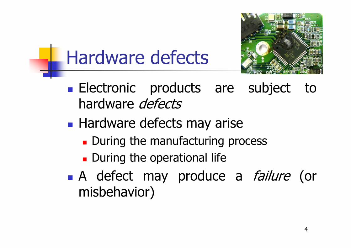
Hardware defects
� Electronic products are subject tohardware defects
� Hardware defects may arise
� During the manufacturing process
� During the operational life
� A defect may produce a failure (ormisbehavior)
4
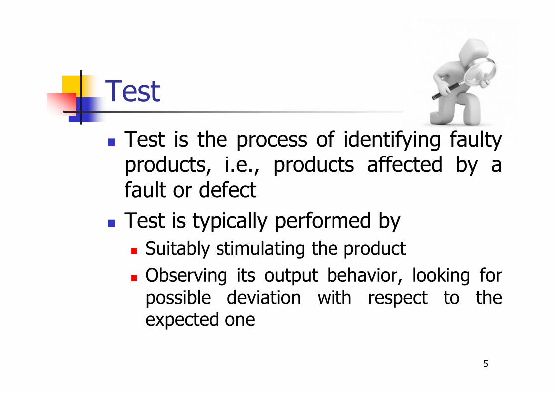
Test
� Test is the process of identifying faultyproducts, i.e., products affected by afault or defect
� Test is typically performed by
� Suitably stimulating the product
� Observing its output behavior, looking forpossible deviation with respect to theexpected one
5
End-of-manufacturing test
� It is typically performed by themanufacturer (of the device, board, orsystem)
� In this case the test
� exploits the complete knowledge about theUnit Under Test (UUT)
� Has full control of the UUT through thetester
6
Fault models
� In principle, a good test should be ableto detect all possible defects
� But enumerating them is practicallyimpossible
� Hence, fault models are adopted
� Example of fault model for logic blocks
� Stuck-at
7
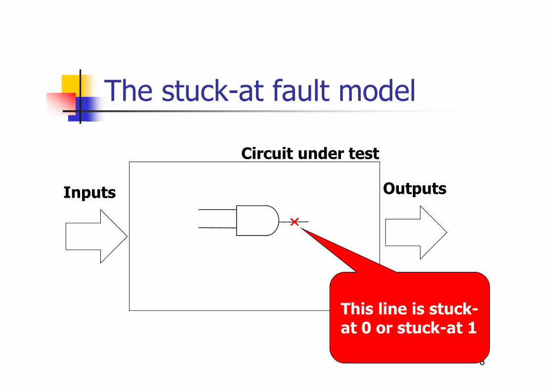
The stuck-at fault model
8
Circuit under test
This line is stuck-at 0 or stuck-at 1
Inputs Outputs
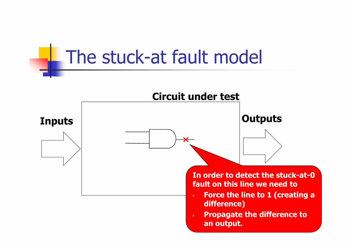
The stuck-at fault model
9
Circuit under test
In order to detect the stuck-at-0 fault on this line we need to
• Force the line to 1 (creating a difference)
• Propagate the difference to an output.
Inputs Outputs

Fault coverage
� Measuring the quality of a test (i.e., ofan input sequence) can be done bycomputing the Fault Coverage (FC):
FC = percentage of faults detected by the input sequence
10
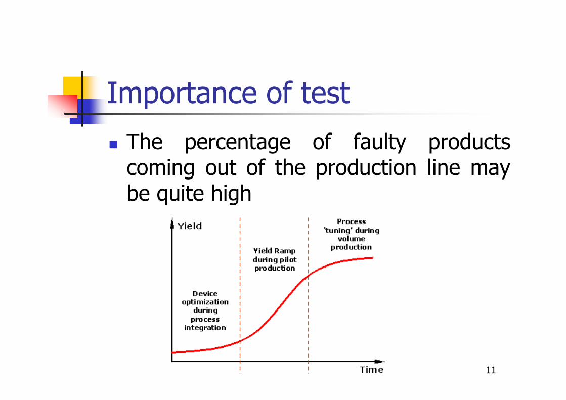
Importance of test
� The percentage of faulty productscoming out of the production line maybe quite high
11
Importance of test
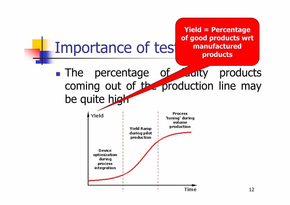
� The percentage of faulty productscoming out of the production line maybe quite high
12
Yield = Percentageof good products wrt
manufacturedproducts
Importance of test
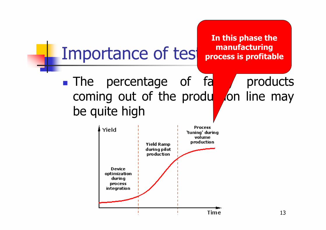
� The percentage of faulty productscoming out of the production line maybe quite high
13
In this phase the manufacturing
process is profitable
Importance of test
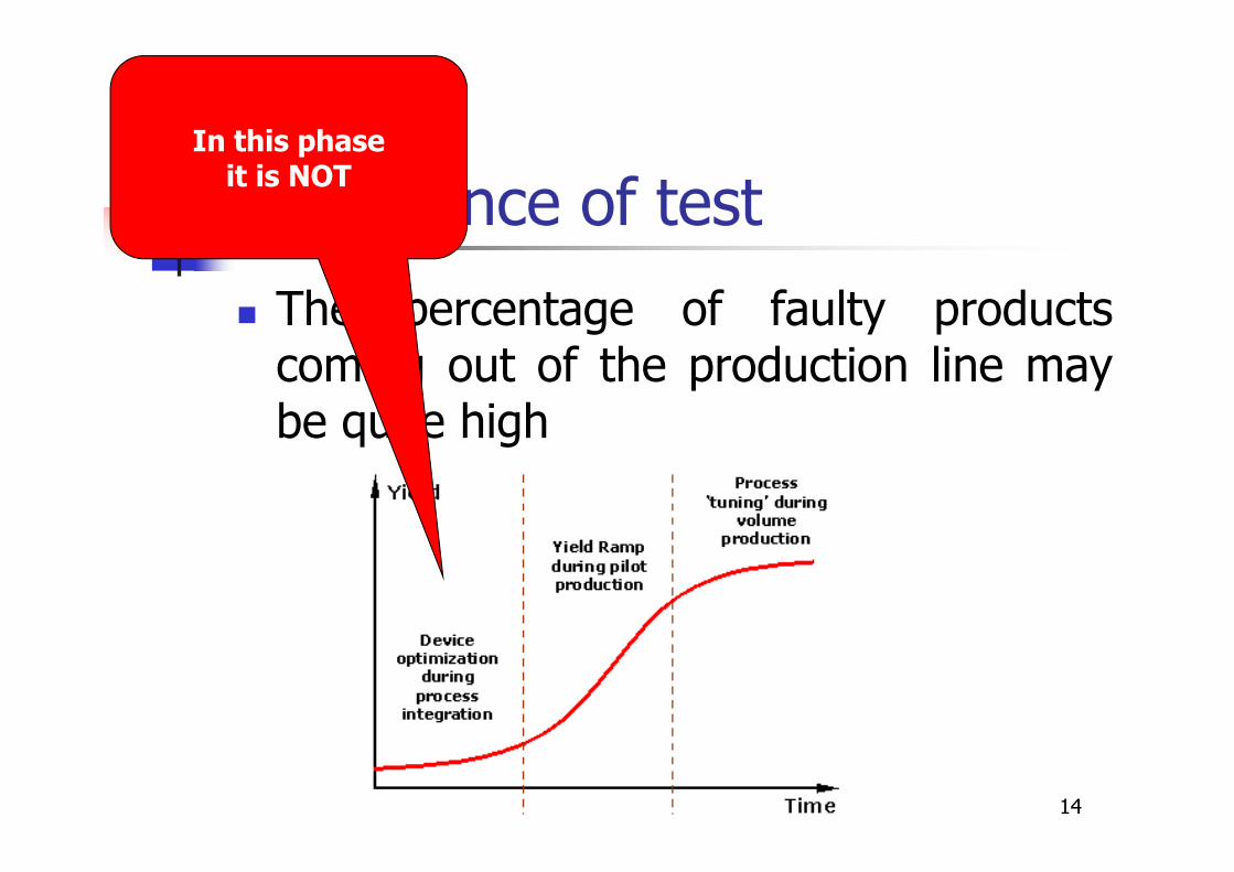
� The percentage of faulty productscoming out of the production line maybe quite high
14
In this phaseit is NOT

Importance of test
� Test is crucial to
� Ensure the quality of the deliveredproducts (volume testing)
� Support the tuning of the manufacturingprocess so that yield is quickly increased
� Test may be VERY expensive
� Mainly because of the cost of the tester
15

Importance of test
� Test is crucial to
� Ensure the quality of the deliveredproducts (volume testing)
� Support the tuning of the manufacturingprocess so that yield is quickly increased
� Test may be VERY expensive
� Mainly because of the cost of the tester
16
In some cases, the cost for test is higher
than the one for manufacturing
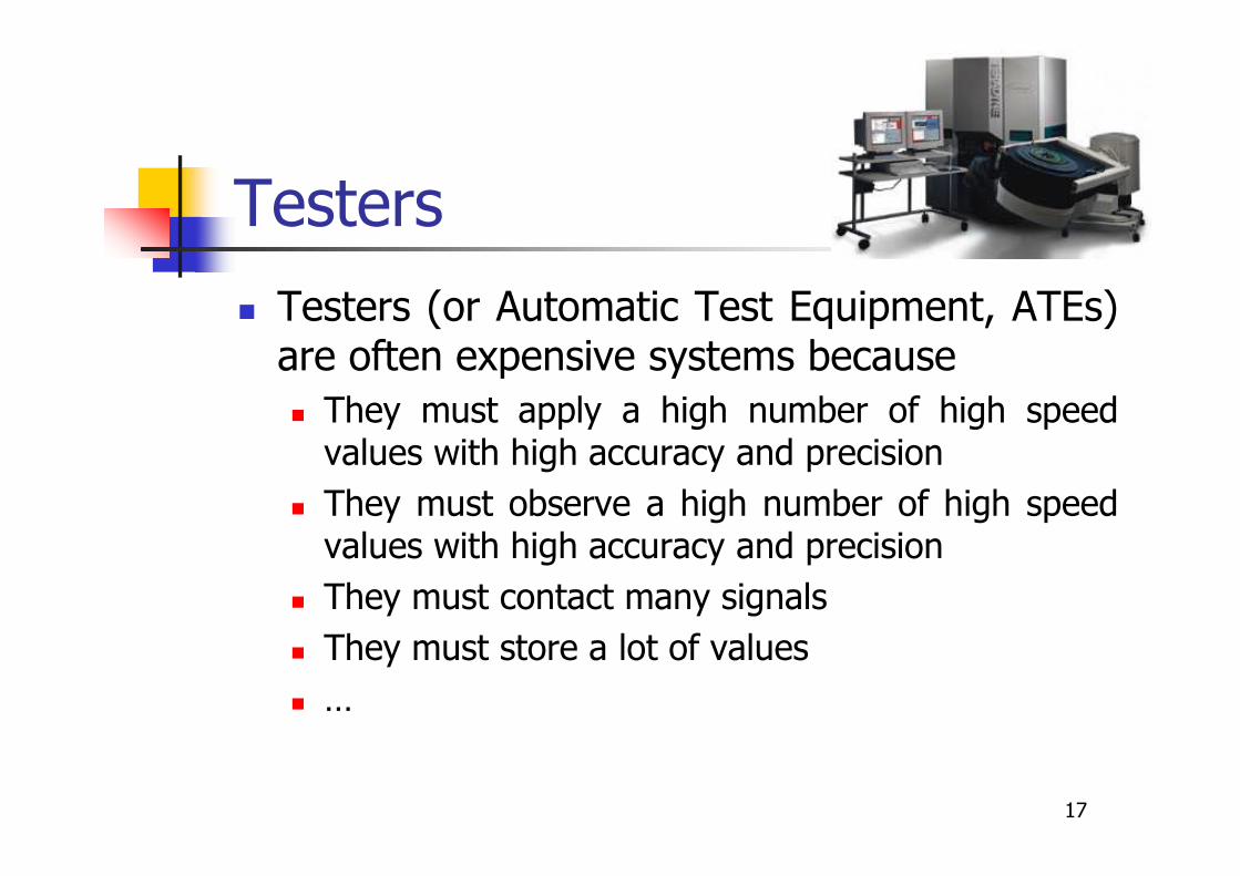
Testers
� Testers (or Automatic Test Equipment, ATEs)are often expensive systems because
� They must apply a high number of high speedvalues with high accuracy and precision
� They must observe a high number of high speedvalues with high accuracy and precision
� They must contact many signals
� They must store a lot of values
� …
17
Design for Testability
� Sometimes it is convenient to suitablymodify the design of a circuit to makethe test easier (i.e., cheaper)
� Examples
� Scan test
� Built-In Self-Test (BIST)
18
19
Scan test
� Generating effective test sequences can beeasily done for combinational circuits, whilefor sequential circuits it is practicallyunfeasible
⇓Designers modify their circuits in such a waythat during the test phase they turn intopseudo-combinational circuits (scan test)
2020
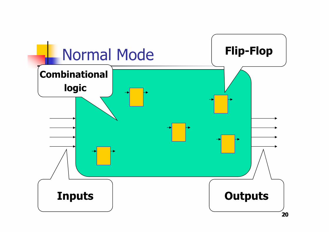
Normal ModeCombinational
logic
Flip-Flop
Inputs Outputs

2121
Test ModeScan
chain
Scan-In
Scan-Out

22
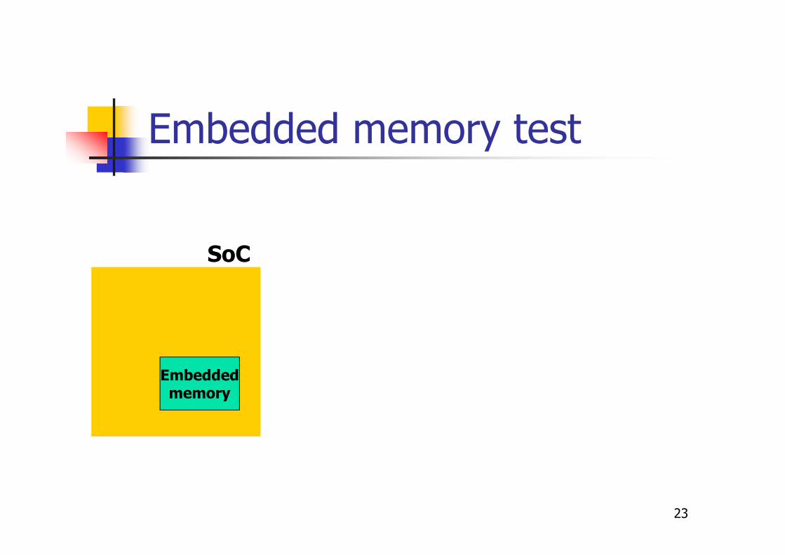
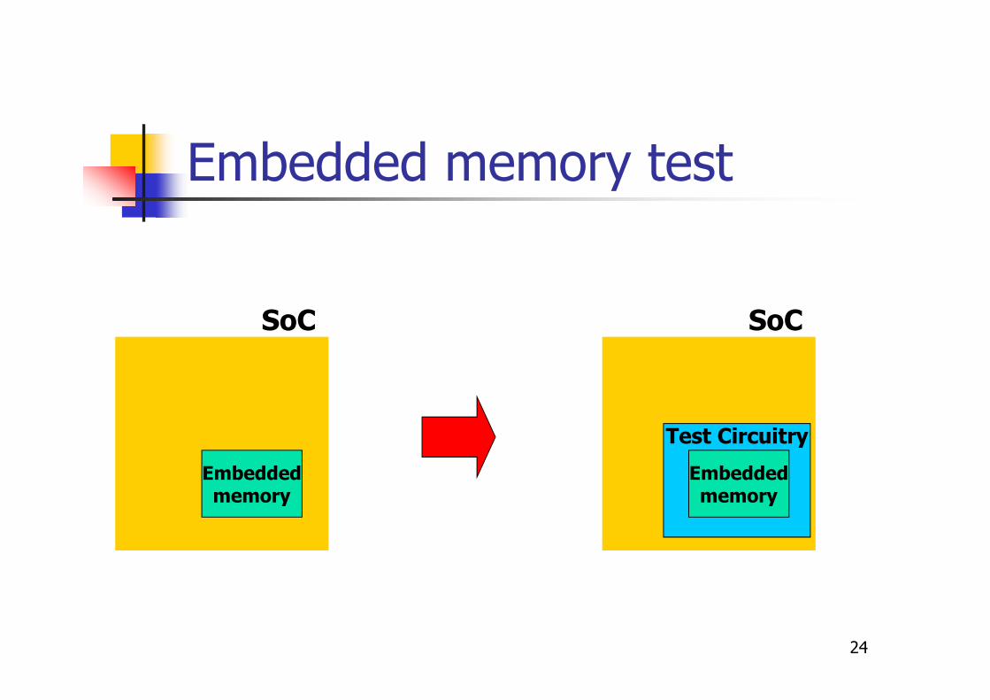
BIST
� Testing memories requires stimulating themwith long sequences of read/write operations;this is impossible for embedded memories
⇓Embedded memories are modified in such away that during test� they are functionally disconnected from the rest of
the circuit� they are controlled/observed by a suitable
circuitry, which generates tests and observeresults
23
Embedded memory test
Embeddedmemory
SoC
24
Embedded memory test
Embeddedmemory
SoC SoC
Embeddedmemory
Test Circuitry
25
Purposes
� The adoption of DfT techniques canallow
� Increasing the test quality� by allowing the detection of a higher percentage
of defects
� Reducing test cost� by allowing the usage of cheaper testers
� Reducing test times� By allowing on-chip at-speed test
26
State of the art of DfT
� Practically all digital VLSI devices todayadopt some DfT technique
� Limitations
� DfT is expensive (in terms of silicon area)
� DfT is often not documented by the siliconmanufacturer ⇒ it cannot be used byothers
� DfT reconfigures the circuit for test; hence,some defects may escape DfT solutions
27
Test of SoCs
� Traditionally, end-of-manufacturing test isperformed by the manufacturer, that ownsfull details about the internal structure of thesystem (and possible DfT structures)� Example: Intel and AMD test their processors fully
knowing their design and implementation
� However, the SoC design paradigm heavilychanged the situation� Sometimes the manufacturer must test a device
including cores which have been designed by thirdparties
� Hence, the manufacturer does not always fullyknow the internal structure of the device undertest

In-field test
� During the operational life new defectsmay arise, e.g., due to aging
� When the product is used in a safety- ormission-critical application, it is crucialto detect these defects as early aspossible, before they may createserious consequences
28
In-field test
� It can be performed
� At the power-on
� During idle periods
� Periodically
� Concurrently
� …
29
In-field test characteristics
� In-field test is rather different than end-of-manufacturing test
� Up to a system company
� No tester
� Limited accessibility/observability
� Duration is a strong constraint
� Often without DfT support
30
31
Incoming Inspection
� It is typically performed by system companieswishing to assess the quality of thecomponents they are going to use
� This step is often required by standards (e.g.,DO-254 for avionics and ISO 26262 forautomotive) if the system is used for asafety-critical application
� The system company does not haveinformation about the internal architectureand implementation of each device (blackbox)
Board test
� It is composed of different steps
� Bare board test
� Test of components
� Test of the populated board
� It uses completely different metrics
� It changes significantly from oneproduct to another
� It is much less automated than IC test32
33
Summary
� Introduction to test
� Functional test
� Functional test of processors
� Functional test of peripheralcomponents
� In-field test
� Conclusions
34
Functional test
� Functional test can be defined in two differentways:
� Definition 1a test performed acting on the functional inputs and observing the functional outputs, only, without resorting to any kind of Design for Testability
35
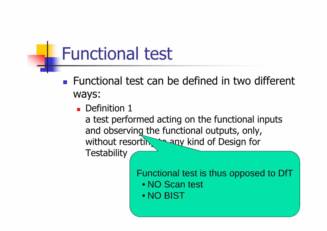
Functional test
� Functional test can be defined in two differentways:
� Definition 1a test performed acting on the functional inputs and observing the functional outputs, only, without resorting to any kind of Design for Testability
Functional test is thus opposed to DfT• NO Scan test• NO BIST
36
Functional test
� Functional test can be defined in two differentways:
� Definition 1a test performed acting on the functional inputs and observing the functional outputs, only, without resorting to any kind of Design for Testability
� Definition 2a test developed on the basis of the functional information about the module under test, only: therefore, it aims at testing the functions rather than the faults (black box testing)

37
Functional test
� Functional test can be defined in two differentways:
� Definition 1a test performed acting on the functional inputs and observing the functional outputs, only, without resorting to any kind of Design for Testability
� Definition 2a test developed on the basis of the functional information about the module under test, only: therefore, it aims at testing the functions rather than the faults
Functional test is now the oppositeof structural test
38
Functional test
� Def. 1 relates to how the test is applied
� Def. 2 relates to how the test isgenerated
� A test may also match both definitions
� Example: a device is tested using somestimuli� generated from functional information,
only, and
� applied without resorting to any DfTfeature

Possible scenarios
� SoC end-of-manufacturing test
� SoC in-field test
� Processor Incoming Inspection
� PCB functional test
39
Scenario #1
� SoC end-of-manufacturing test
� Functional test is used to detect defectswhich are not detected by other methods
� Specially developed test programs are used
� A tester is used (full control of inputs andoutputs)
� Fault coverage can be computed (the netlistis available)
40
Scenario #2
� SoC in-field test
� Functional test is sometimes usedbecause it is the only feasible solution
� No DfT
� No tester
� Limited resources
� Flexible
� Specially developed test programs
� Fault coverage can be computed 41
Scenario #3
� Processor (MCU) Incoming Inspection
� Functional test is the only feasiblesolution
� Simple test programs are used (e.g.,activating all instructions)
� Which metric to assess the test quality?
42
Scenario #4
� PCB functional test
� PCB test includes different steps
� Bare board testing
� Component test
� Populated board test
� Functional test is often the final step
� Suitable applications are often used
� Metrics?43

44
Summary
� Introduction to test
� Functional test
� Functional test of processors
� Functional test of peripheralcomponents
� In-field test
� Conclusions
Functional test of processors
� It is used in different scenarios
� End-of-manufacturing of processors
� End-of-manufacturing of SoCs
� End of manufacturing of PCBs
� Incoming inspection of processors
� In-field test of PCBs
� …
45
46
Functional test of processors
� A functional test for a processor isusually based on
� Uploading some test code in an accessiblememory
� Forcing the processor to execute the code
� Checking the produced results (e.g., inmemory)
� This approach is sometimes denoted asSoftware-Based Self-Test (SBST)
Psarakis et al., D&T, 2010
47
Test Protocol
� Upload the Test Program in the codememory (or cache)
� Force the processor to execute the TestProgram
� Check the results written in memory
48
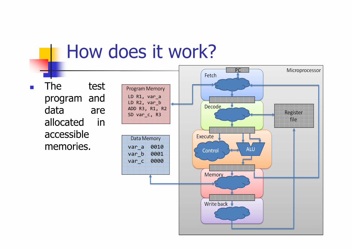
How does it work?
� The testprogram anddata areallocated inaccessiblememories.
LD R1, var_a
LD R2, var_b
ADD R3, R1, R2
SD var_c, R3
var_a 0010
var_b 0001
var_c 0000
49
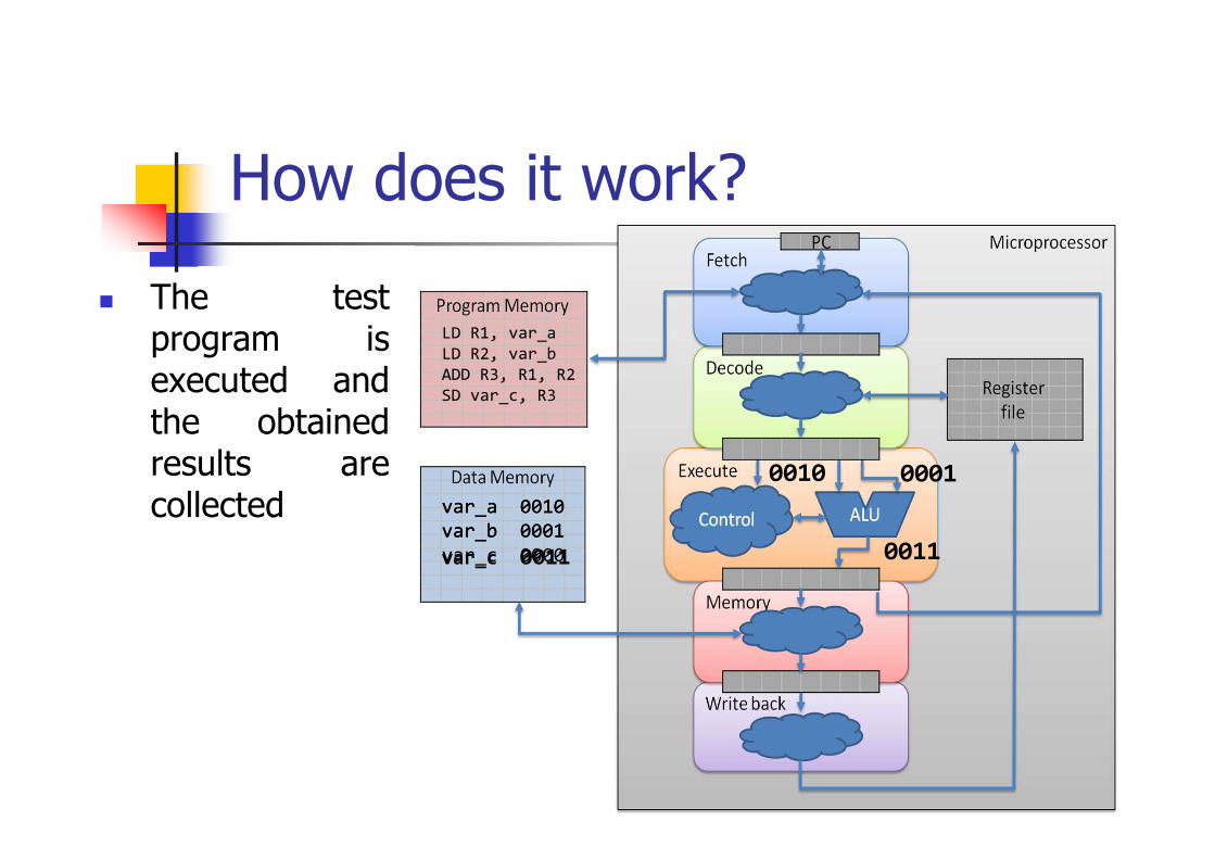
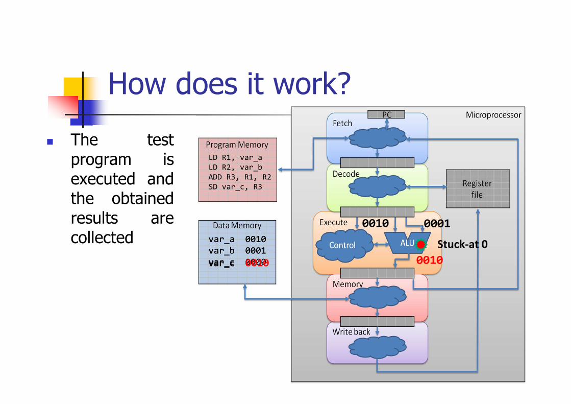
How does it work?
� The testprogram isexecuted andthe obtainedresults arecollected
LD R1, var_a
LD R2, var_b
ADD R3, R1, R2
SD var_c, R3
var_a 0010
var_b 0001
var_c 0000
0010 0001
0011
var_a 0010
var_b 0001
var_c 0011
50
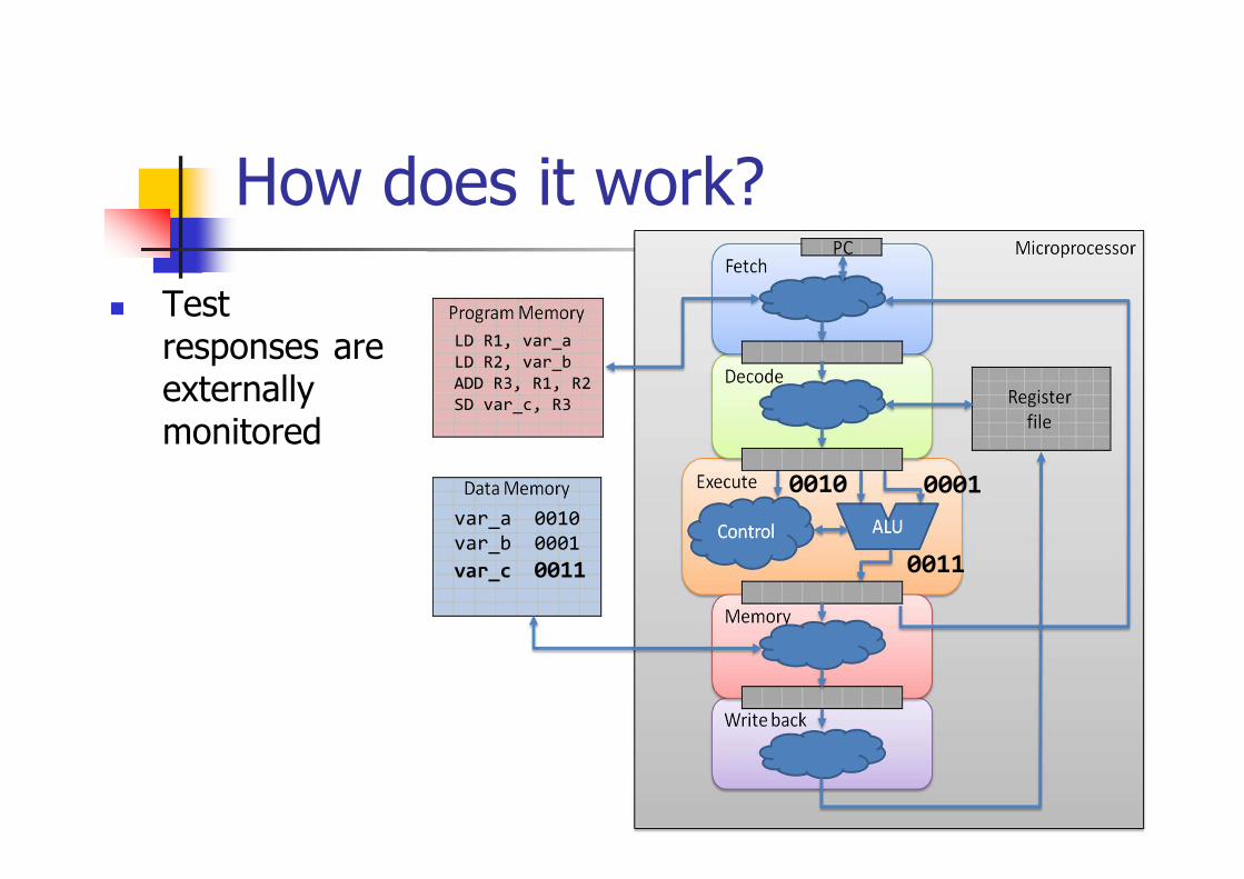
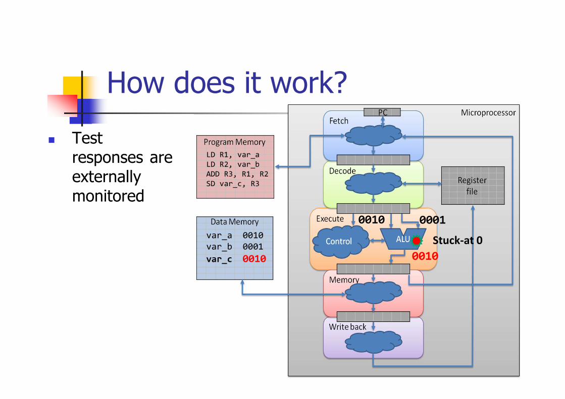
How does it work?
� Testresponses areexternallymonitored
LD R1, var_a
LD R2, var_b
ADD R3, R1, R2
SD var_c, R3
0010 0001
0011
var_a 0010
var_b 0001
var_c 0011
51
How does it work?
LD R1, var_a
LD R2, var_b
ADD R3, R1, R2
SD var_c, R3
var_a 0010
var_b 0001
var_c 0000
0010 0001
0010
var_a 0010
var_b 0001
var_c 0010
Stuck-at 0
� The testprogram isexecuted andthe obtainedresults arecollected
52
How does it work?
LD R1, var_a
LD R2, var_b
ADD R3, R1, R2
SD var_c, R3
0010 0001
var_a 0010
var_b 0001
var_c 0010 0010
Stuck-at 0
� Testresponses areexternallymonitored
53
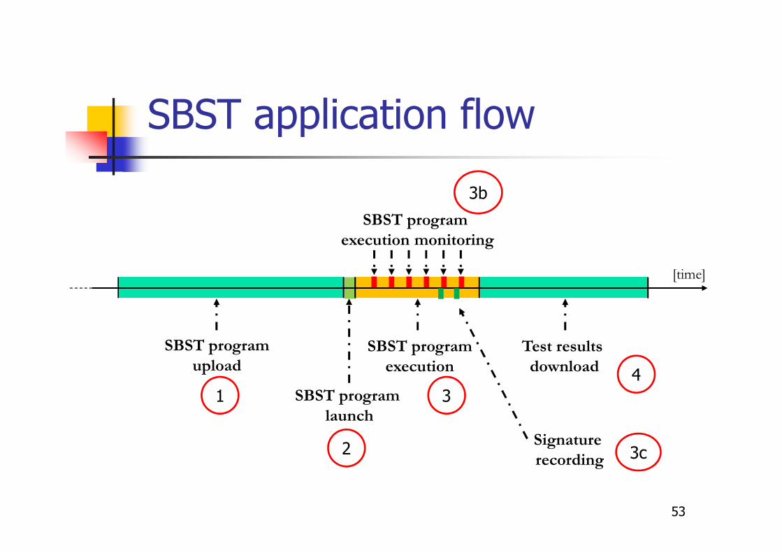
SBST application flow
SBST program
upload
SBST program
execution
[time]
Test results
download
SBST program
launch
SBST program
execution monitoring
1
2
3
3b
4
Signature
recording 3c
54
� Some key aspects have to beconsidered:
� Code/Data memories availability andupload time
� Test procedure launching method
� Monitoring capabilities
� Test results storage and download
SBST application procedure
55
� The test program is run by the processorcore, fetching instructions fromsuitable/reserved memory spaces:� RAM cores
� Test programs are uploaded every time they have to be executed
� Suitable for final tests at the end of manufacturing flow
� Flash cores� Test programs are uploaded just once
� They are run any time it is required
� Suitable to implement a reliability framework
Test program upload
56
� Test program activation may be carried outby:� The system reset
� Suits for manufacturing test
� Some interrupt/exception mechanism� Forced from the outside through the wrapper, or� Internally raised by means of a SW exception call
� The OS by implementing a scheduling strategythat launches the test program
� At regular intervals � During idle periods� Suits for on-line SBST program execution
Test program launch
57
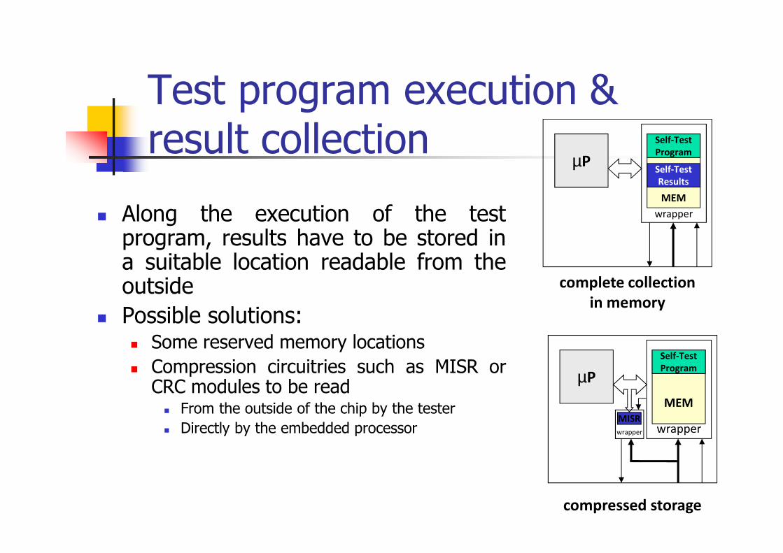
� Along the execution of the testprogram, results have to be stored ina suitable location readable from theoutside
� Possible solutions:� Some reserved memory locations
� Compression circuitries such as MISR orCRC modules to be read
� From the outside of the chip by the tester
� Directly by the embedded processor
Test program execution & result collection
µP
MEM
wrapper
Self-Test
Program
Self-Test
Results
µP
MEM
wrapper
Self-Test
Program
MISR
complete collection
in memory
compressed storage
wrapper
58
Test stimuli generation
� May exploit
� Stimuli from the designer (e.g., intendedfor design validation)
� Random stimuli
� Ad hoc stimuli, manually or automaticallygenerated
� In any case, a test coverage metricshould be available

59
Test Program Generation
� Can be done
� Manually, or
� Automatically

60
Manual Methods
� Empirical methods
� Global methods
� Unit-oriented methods
61
Empirical methods
� They are based on the knowledge of theInstruction Set Architecture (ISA), only
� Examples� All instructions
� All instructions with all addressing modes
� A set of code fragments to stimulate all units
� ...
� Very approximated metrics are normally used
62
Global methods
� Aim at testing the whole processorstarting from the ISA, only
� They are based on a systematicapproach
� They do not guarantee a given faultcoverage, although significant valuescan normally be reached
63
Method by Thatte and Abraham
� Was proposed in 1980 for an 8-bit processor
� Works on the RTL description of a simpleprocessor, only, as it can be extracted from auser manual
� Defines rules to build a graph describing theinstruction behavior wrt registers
� Defines a set of functional fault models
� Defines some procedures to generatesequences of instructions addressing theabove fault models Thatte and Abraham,
Trans. on Comp. , 1984

64
Functional fault models
� For the register decoding function� When a register is written
� All the registers are written
� No register is written
� Another register is written
� For the instruction decoding and controlfunction
� For the data storage function
� For the data transfer function
� For the data manipulation function

65
Procedures for test generation
� They allow detecting all the previouslylisted faults (one at a time)
� Example
� To test the register decoding faults
� Initialize all registers to a given value ZERO
� For every register R
� Write a value ONE in R
� Read R
� Read the other registers (they should store ZERO)
66
Unit-oriented methods
� They provide a sequence of operations ableto exhaustively cover a given unit withrespect to static and/or dynamic faults
� Examples
� Adder
� Multiplier
� Cache controller
� Branch Prediction Unit
� …
67
Adder/Multiplier
� The adder and the multiplier are oftenlarge combinational blocks within theprocessor core
� Functional test programs for each ofthem may be generated in differentways:
� Resorting to a combinational ATPG
� Resorting to a specific algorithm
68
Resorting to an ATPG
� Extract the logic for the adder
� Run a combinational ATPG on it
� Transform each vector into aninstruction (ATPG values are the inputparameters)
� Add instructions to check result
69
Resorting to an ad hoc algorithm
� Based on a set of loops
� Stimulate the adder with a propersequence of selected values
� Able to detect not only static faults(e.g., stuck-at faults) but also dynamicones (e.g., delay faults)
Gizopoulos et al., ITC, 1997
70
Caches
� Most processors includes caches
� Their test is normally performed bysilicon producers through BIST
� The BIST facilities are seldomaccessible and documented
� Functional test is an alternative solution
Di Carlo et al., Trans. onComp., 2011
71
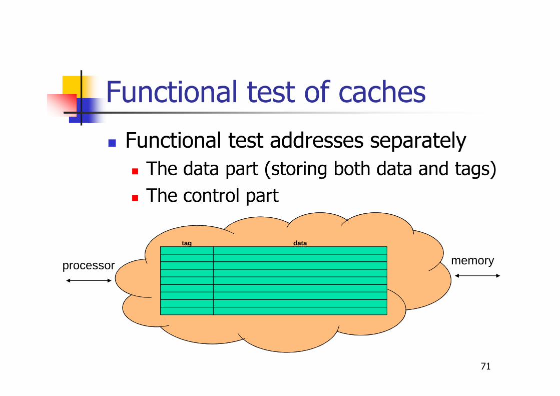
Functional test of caches
� Functional test addresses separately
� The data part (storing both data and tags)
� The control part
tag data
processor memory

72
Testing the data part in a data cache
� It means testing a memory; therefore,the test mimics a March algorithm
� The test is based on a proper sequenceof memory accesses
� Once the mapping policy implementedby the cache is known, transforming aMarch algorithm into the correspondingsequence of LOAD/STORE instructionsis straightforward
73
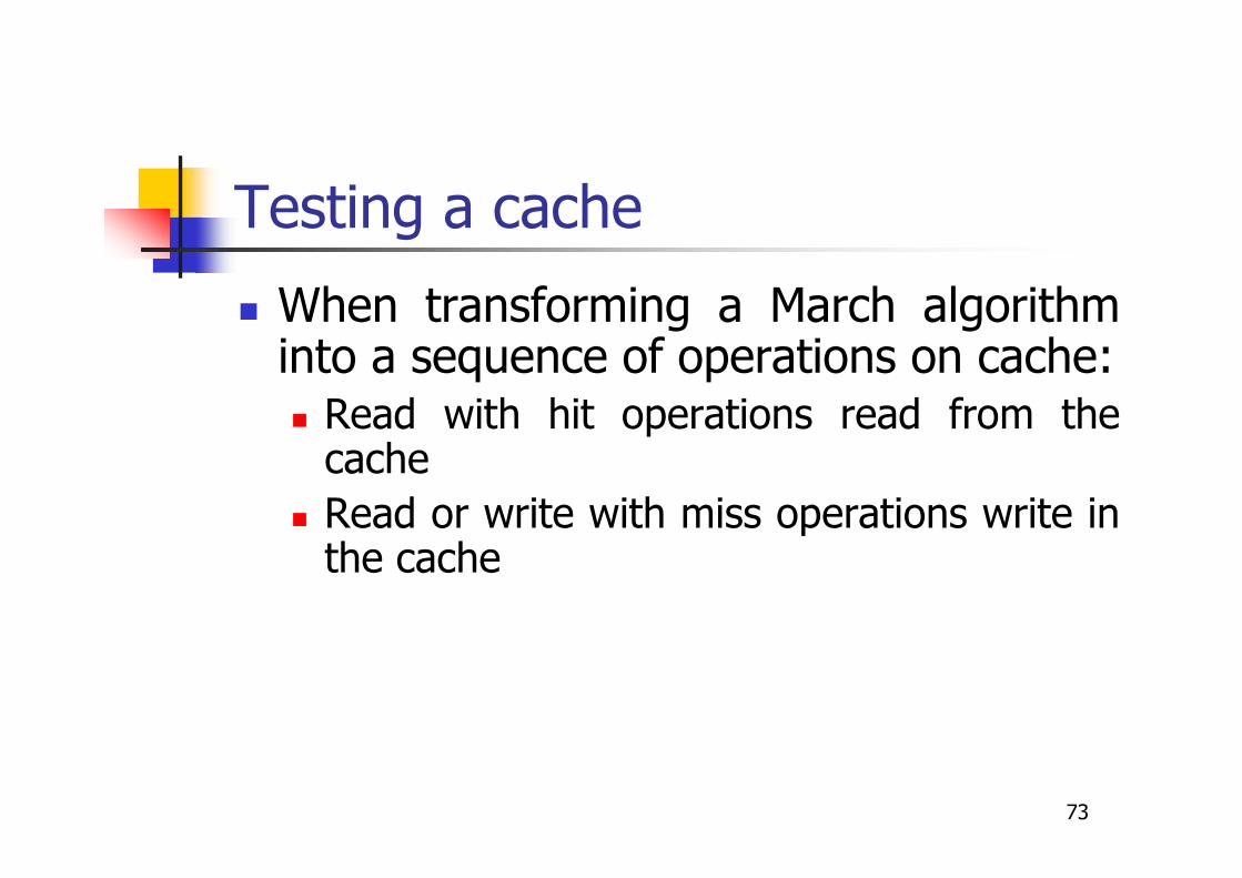
Testing a cache
� When transforming a March algorithminto a sequence of operations on cache:� Read with hit operations read from the
cache
� Read or write with miss operations write inthe cache
74
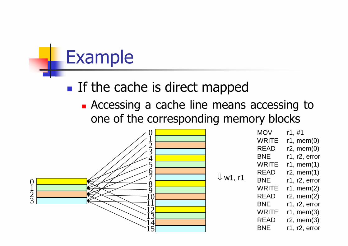
Example
� If the cache is direct mapped
� Accessing a cache line means accessing toone of the corresponding memory blocks
0123
0123456789
101112131415
MOV r1, #1WRITE r1, mem(0)READ r2, mem(0)BNE r1, r2, errorWRITE r1, mem(1)READ r2, mem(1)BNE r1, r2, errorWRITE r1, mem(2)READ r2, mem(2)BNE r1, r2, errorWRITE r1, mem(3)READ r2, mem(3)BNE r1, r2, error
⇓ w1, r1
75
Testing the tag part
� This task is much more difficult,because tags can only indirectly be readand written
� Reading a tag means accessing a cacheline whose content is known, and thenchecking whether the expected hit ormiss was performed
� Writing a tag means forcing a miss on agiven cache line
76
Problems
� If the cache is set associative with LRUreplacement policy, performing two writeoperations on the same cache line isimpossible
� In fact, the first operation marks the line asMost Recently Used, and the following accessaffects a different line
� The only solution is to add further operationswithin the March algorithm
� However, this may reduce the effectivenessof the March algorithm itself
77
Testing an instruction cache
� This task is even more difficult
� It requires executing in a proper order asequence of proper instructions placedin proper positions in memory
78
Cache controller
� Deeply embedded� Hard to control: suitable sequence of memory
accesses� Hard to observe: mainly by checking whether any
access produced a hit or miss
� Faults may cause either data or performancemisbehaviors
� Testing the data part does not fully cover thecontrol part (about 20% of stuck-at faultsremain uncovered)
� The parts that remain uncovered are mainlythose concerning the substitution policy

79
Observing the cache controller behavior
� If we are interested in faults affecting thestatic behavior (i.e., changing the produceddata)� We can observe the data in memory at the end of
the test
� If we are interested in faults affecting thedynamic behavior (i.e., changing theperformance)� We have to evaluate the time required to execute
the test program
80
Measuring the execution time
� This task can be performed in differentways
� Resorting to some counter existing in thesystem
� Resorting to some performance counter (ifthe processor offers this facility)
� Resorting to some debug feature
� Resorting to some ad hoc hardware

81
Cache controller functional test
� Testing the cache memory is notenough to test the cache controller
� Cache controller functions are relativelystandard
� Developing an implementation-independent parametric test algorithmis feasible
82
Branch Prediction Units
� Branch Prediction Units (BPUs) areoften included in modernmicroprocessor/microcontrollers
� Sometimes they include relatively largememories and logic
� Faults in BPUs� may seriously affect the processor
performance
� rarely affect the dataSanchez & Sonza, Trans.on VLSI, 2015

83
BPUs
� They normally take two forms
� Branch History Table (BHT)
� Returns prediction
� Branch Target Buffer (BTB)
� Returns prediction and expected target address
84
Automatic methods
� Generating the test program can bedone in an automatic manner resortingto three approaches:
� Randomizers
� Macro-based methods
� Formal methods
� Evolutionary-based methods

85
Randomizers
� Data and instructions are randomlygenerated, following some constraintsthat� Guarantee the correctness of the test
program
� Guide the generation towards the mostcritical areas
� Test programs may be significantly longto execute and large to store
86
FRITS
� Intel heavily exploits randomizers forboth testing and design validation
� FRITS is the internal tool developed for
� Generating random programs
� Expressing constraints
Parvathala et al., ITC,2002
87
Macro-based approach
� A Macro is the basic block of the TestProgram
� Each macro:
� Focuses on a single target instruction in the µPInstruction Set
� Includes the code for
� Exciting the instruction functionalities
� Making the results observable
� Some optimization technique is required for
� Selecting the best set of macros
� Assigning values to parametersCorno et al., DATE,
2001
88
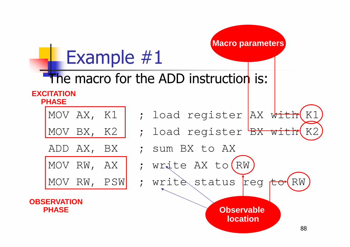
Example #1The macro for the ADD instruction is:
MOV AX, K1 ; load register AX with K1
MOV BX, K2 ; load register BX with K2
ADD AX, BX ; sum BX to AX
MOV RW, AX ; write AX to RW
MOV RW, PSW ; write status reg to RW
Observable location
EXCITATIONPHASE
OBSERVATIONPHASE
Macro parameters

89
Example #2
The macro for the JG instruction is:
MOV BX, 0 ; clear BX
MOV AX, K1
CMP AX, K2 ; compare AX with K2
JG Label ; jump if AX > K2
MOV BX, 1 ; move 1 to BX
Label: MOV RW, BX; write BX to RW

90
Macro Selection andParameter Optimization
do{ m = select_a_macro();
O = select_the_operands(m);F = compute_detected_faults(m, O);if( F is not empty )
add m(O) to the test program;}while( stopping_condition() == FALSE );
91
Macro Selection
� The final Test Program should have minimallength
� An adaptive approach can be adopted:
� Macros are selected on a random basis
� A selection probability is associated to each macro
� At the beginning, all macros have the sameselection probability
� Each time a macro is selected, its selectionprobability is increased if it detects at least onefault, decreased elsewhere

92
Operand Selection
� An Evolutionary approach can beadopted:
� Random values are initially chosen
� An evaluation function is associated toeach set of values
� Current values are possibly improved usinga Genetic Algorithm
93
Evaluation Function
� It is based on three terms:
� A first order term, corresponding to thenumber of detected faults
� A second order term, corresponding to thenumber of excited faults
� A third order term, corresponding to theactivity caused by the excited faults
� The value of the evaluation function iscomputed by fault simulation
94
Experimental Results
� A macro-based method was evaluatedresorting to:
� A prototype (named ATPGS) implementingthe proposed approach
� An Intel 80C51 model

95
ATPGS architecture
ATPGKernel
Evolutionaryengine
FaultSimulator
µPnetlist
FaultList
MacroLibrary
TestProgram
Macro + Operands
Detected Faults

96
Case Study: i8051 µC
� 8-bit microprocessor developed by Intelin the 80s
� Quite old but still popular (USB)
� 128 bytes directly-accessible data memory+ 32 bytes bit-addressable data memory
� 64KB external memory accessible using aspecial instruction (MOVX)
� 4KB internal + 64KB external programmemory

97
Case Study: i8051 µC (2)
� RT-Level description
� 7,500 VHDL lines
� 4 KB program + 2 KB data memory
� Gate-level description
� 12K gates
� 28,792 stuck-at faults
98
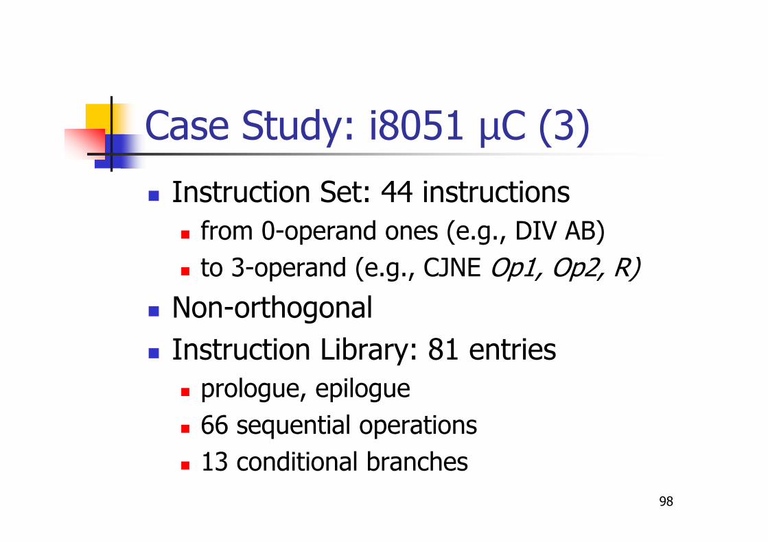
Case Study: i8051 µC (3)
� Instruction Set: 44 instructions
� from 0-operand ones (e.g., DIV AB)
� to 3-operand (e.g., CJNE Op1, Op2, R)
� Non-orthogonal
� Instruction Library: 81 entries
� prologue, epilogue
� 66 sequential operations
� 13 conditional branches
99
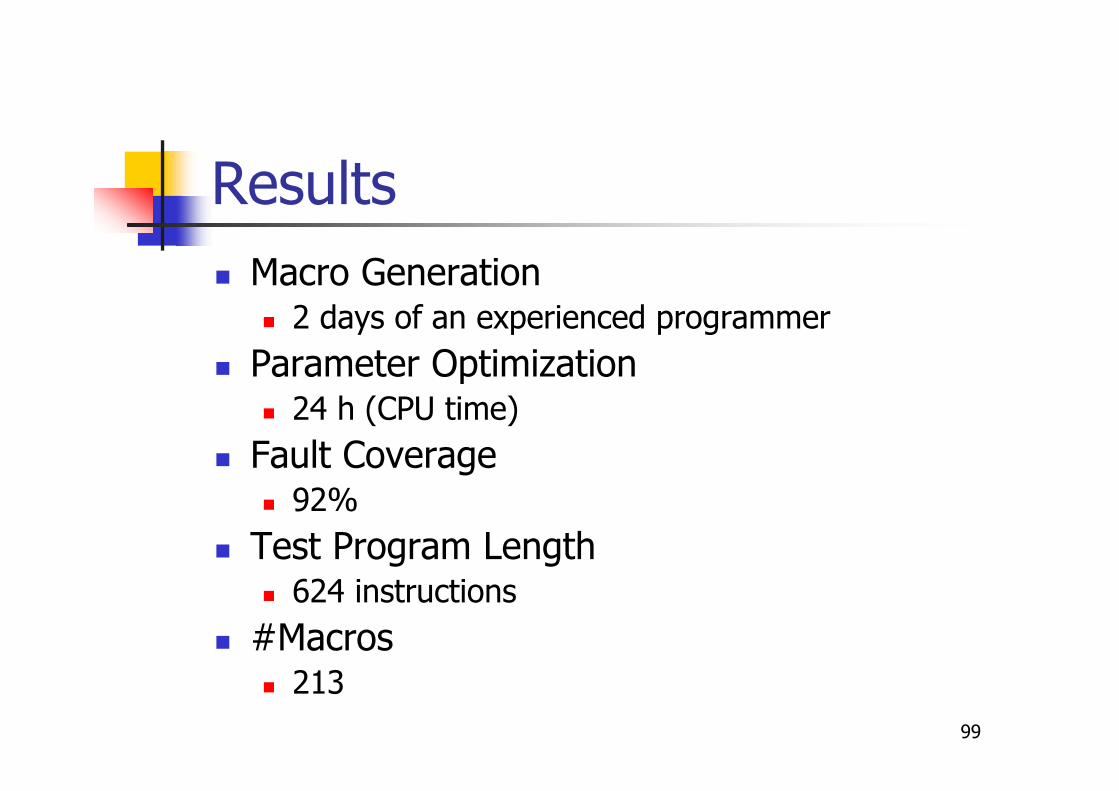
Results
� Macro Generation� 2 days of an experienced programmer
� Parameter Optimization� 24 h (CPU time)
� Fault Coverage� 92%
� Test Program Length� 624 instructions
� #Macros� 213
100
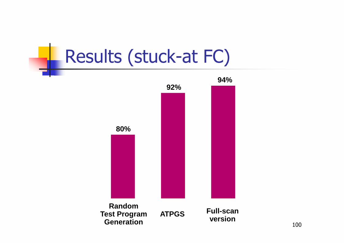
Results (stuck-at FC)
80%
92%94%
RandomTest ProgramGeneration
ATPGS Full-scanversion
101
Result analysis
� Most of the undetected faults are in theDivider:
� better results could be obtained by runninga combinational ATPG for computing theoptimum parameters and removinguntestable faults
� A nearly complete fault coverage hasbeen obtained for the Control Unit
Formal methods
� Recently, it was demonstrated thatformal techniques (e.g., based of ModelCheckers) can generate functional testprograms even for relatively largepipelined processors
102
Riefert et al., DATE, 2014
Advantages
� The method can
� Generate the shortest test sequence foreach fault
� Identify untestable faults
� Support further constraints (e.g., for in-field test)
103
Limitations
� CPU and memory requirements may preventthe scalability to large processors
104

105
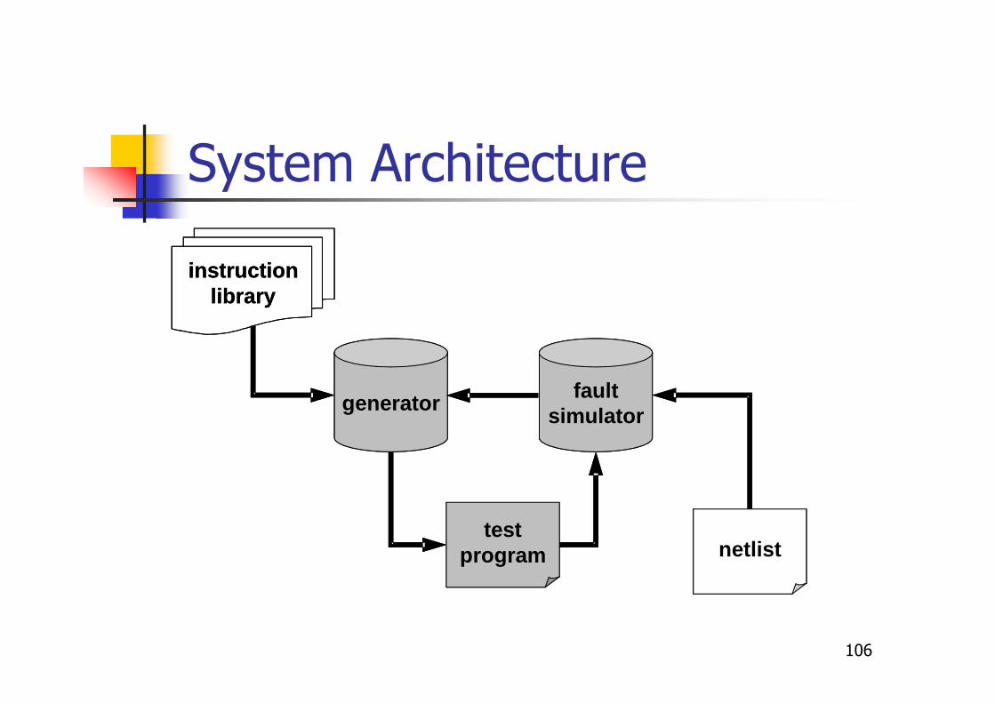
The µGP approach
� Semi-automatic Test Programgeneration
� Based on an evolutionary algorithm(named µGP)
� Suitable internal representation,evaluation function and operators aredefined
� A system architecture for automatic testprogram generation has been devised
Sanchez et al., Evolutionary Optimization: the µGP toolkit,
Springer, 2011
106
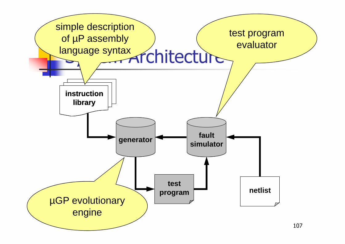
System Architecture
generator
testprogram
instructionlibrary
netlist
faultsimulator
generator
testprogram
instructionlibrary
netlist
faultsimulator
107
System Architecture
generator
testprogram
instructionlibrary
netlist
faultsimulator
generator
testprogram
instructionlibrary
netlist
faultsimulator
simple description of µP assembly language syntax
test program evaluator
µGP evolutionary engine
Advantages
� The method is able to always generatea test program
� Flexibility: by suitably changing thefitness function, different goals can bepursued
108

Limitations
� CPU requirements may limit thescalability of the method
109

110
Experimental evaluation
� Intel 80C51 model
� Sun Enterprise 250 running at 400 MHzwith 2 GB RAM
� Test program generated in few days
� Computational effort is mainly due to faultsimulations
� Evolutionary calculations requirednegligible CPU time
111
Test Programs Comparison
� General applications� Fibonacci, int2bin
� Exhaustive test bench� provided by 8051 designer
� ATPGS� DATE01
� Random (comparable CPU)� Same number of random test programs
� Same number of random sequences of macros(DATE01)
112
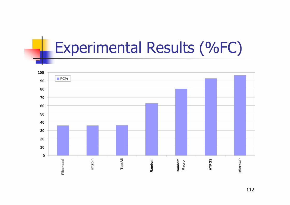
Experimental Results (%FC)
0
10
20
30
40
50
60
70
80
90
100
Fib
on
acci
int2
bin
Tes
tAll
Ran
do
m
Ran
do
m
Mac
ro
AT
PG
S
Mic
roG
P
FC%
113
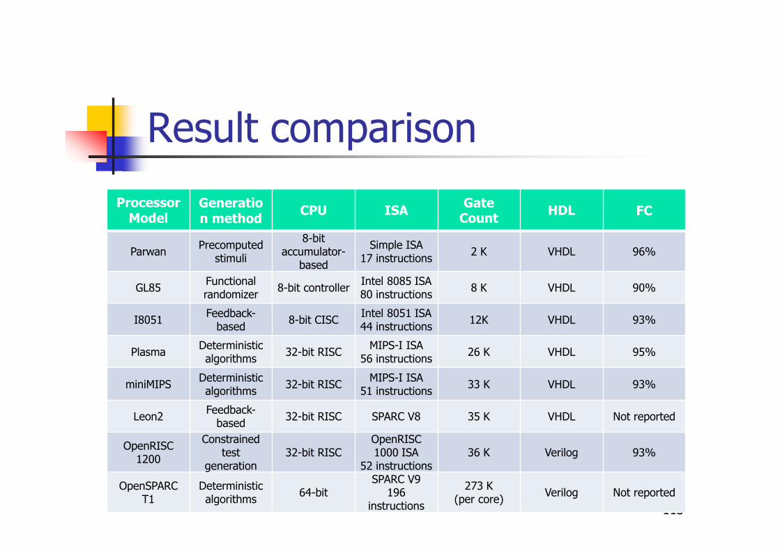
Result comparison
Processor Model
Generation method
CPU ISAGate
Count HDL FC
ParwanPrecomputed
stimuli
8-bit accumulator-
based
Simple ISA 17 instructions
2 K VHDL 96%
GL85Functional randomizer
8-bit controllerIntel 8085 ISA80 instructions
8 Κ VHDL 90%
I8051Feedback-
based8-bit CISC
Intel 8051 ISA44 instructions
12K VHDL 93%
PlasmaDeterministic algorithms
32-bit RISCMIPS-I ISA
56 instructions26 K VHDL 95%
miniMIPSDeterministic algorithms
32-bit RISCMIPS-I ISA
51 instructions33 K VHDL 93%
Leon2Feedback-
based32-bit RISC SPARC V8 35 K VHDL Not reported
OpenRISC 1200
Constrained test
generation32-bit RISC
OpenRISC 1000 ISA
52 instructions36 K Verilog 93%
OpenSPARC T1
Deterministic algorithms
64-bitSPARC V9
196 instructions
273 K (per core)
Verilog Not reported
VLIW processors
� They are often used in embeddedsystems when digital signal processingis required
� They are characterized by
� Regular structure
� Customizable configuration
� No (or limited) control circuitry
114
Functional test of VLIWs
� Effective test algorithms (developed fortraditional processors) can be used for mostmodules
� Some modules (e.g., the register file)requires special test algorithms
� Test program generation can be fullyautomated, once the specific VLIWarchitecture is known
� The key issue is minimizing the total test timeand test code size
115
Sabena et al., Trans. on VLSI, 2014
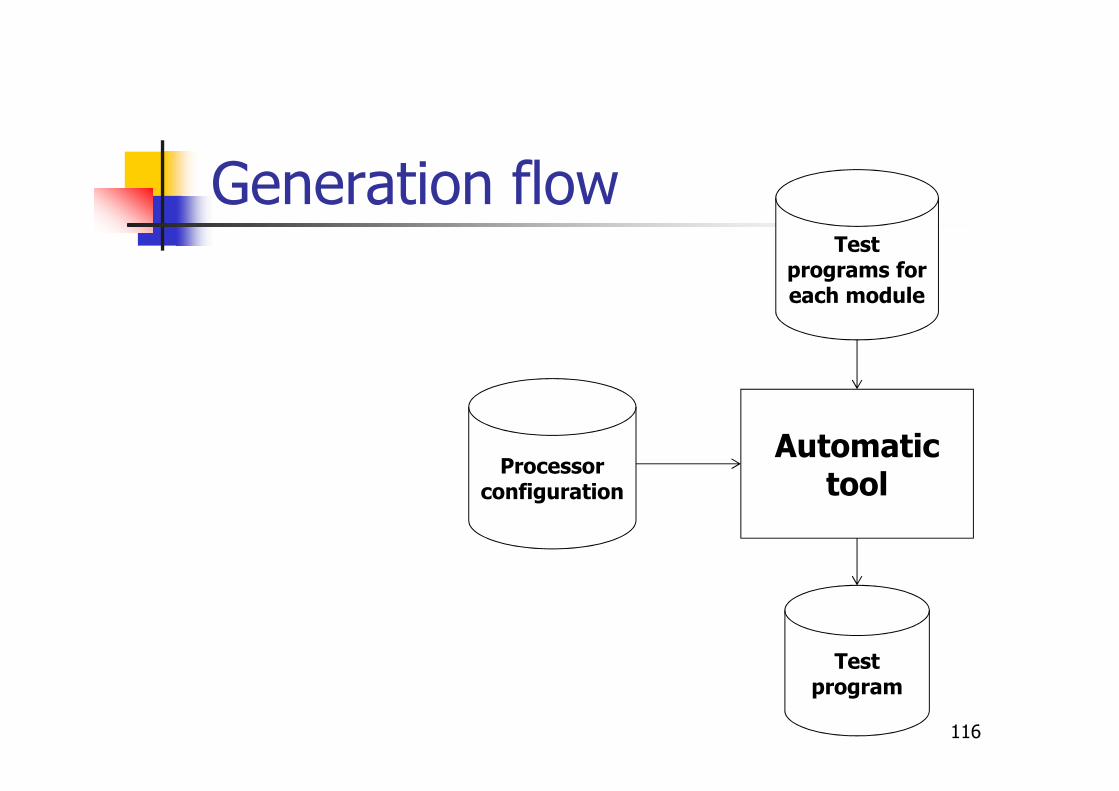
Generation flow
116
Test programs for each module
Processor configuration
Automatictool
Test program
Experimental data
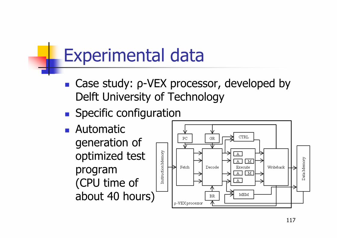
� Case study: ρ-VEX processor, developed by Delft University of Technology
� Specific configuration
� Automatic generation of optimized test program (CPU time of about 40 hours)
117

Results
118
ρ-VEX Components Faults [#]Fault
CoverageClock
Cycles [#]
Fetch 2,156 99.2% 1,028
Decode 269,196 98.1% 760
Execute
4 ALUs 75,554 98.3% 4,580
2 MULs 37,244 98.6% 2,253
MEM 1,730 97.2% 1,280
Writeback 1,420 98.1% 1,180
Total 387,290 98.2% 11,081

119
Summary
� Introduction to test
� Functional test
� Functional test of processors
� Functional test of peripheralcomponents
� In-field test
� Conclusions

120
Peripheral testing
� Peripheral cores can also be tested viafunctional test
� In this case the test requires
� A suitable test program
� To program the peripheral
� To exercise the peripheral
� Some external data (either in input oroutput)
Apostolakis et al., D&T, 2009
121
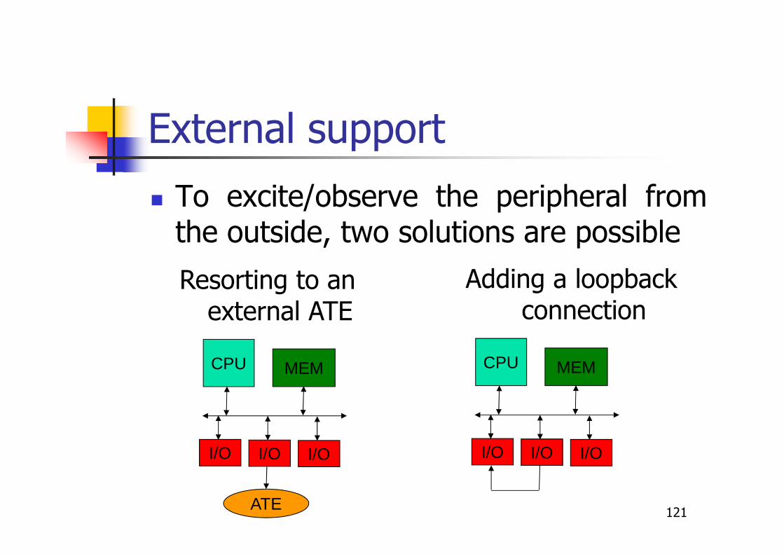
External support
� To excite/observe the peripheral fromthe outside, two solutions are possible
CPU MEM
I/O I/O I/O
ATE
Resorting to an external ATE
CPU MEM
I/O I/O I/O
Adding a loopbackconnection
122
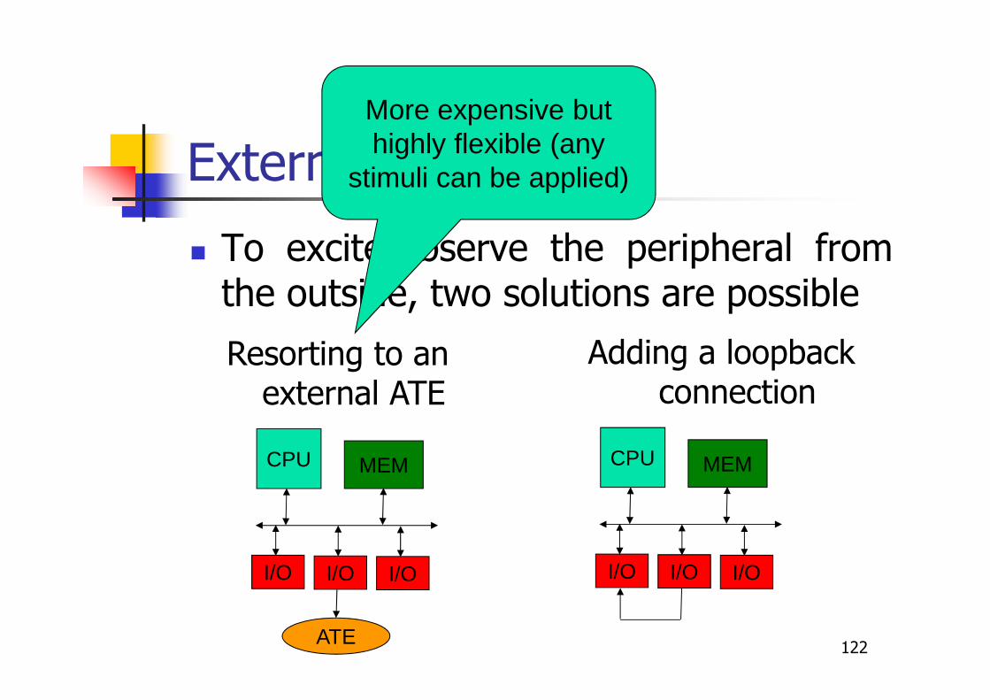
External support
� To excite/observe the peripheral fromthe outside, two solutions are possible
CPU MEM
I/O I/O I/O
ATE
Resorting to an external ATE
CPU MEM
I/O I/O I/O
Adding a loopbackconnection
More expensive but highly flexible (any
stimuli can be applied)
123
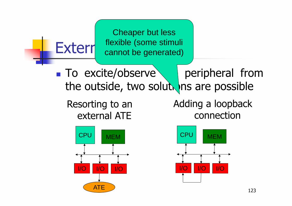
External support
� To excite/observe the peripheral fromthe outside, two solutions are possible
CPU MEM
I/O I/O I/O
ATE
Resorting to an external ATE
CPU MEM
I/O I/O I/O
Adding a loopbackconnection
Cheaper but less flexible (some stimuli cannot be generated)

124
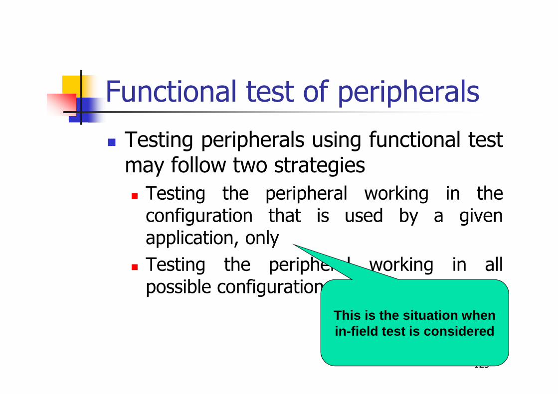
Functional test of peripherals
� Testing peripherals using functional testmay follow two strategies
� Testing the peripheral working in theconfiguration that is used by a givenapplication, only
� Testing the peripheral working in allpossible configurations
125
Functional test of peripherals
� Testing peripherals using functional testmay follow two strategies
� Testing the peripheral working in theconfiguration that is used by a givenapplication, only
� Testing the peripheral working in allpossible configurations
This is the situation whenin-field test is considered
126
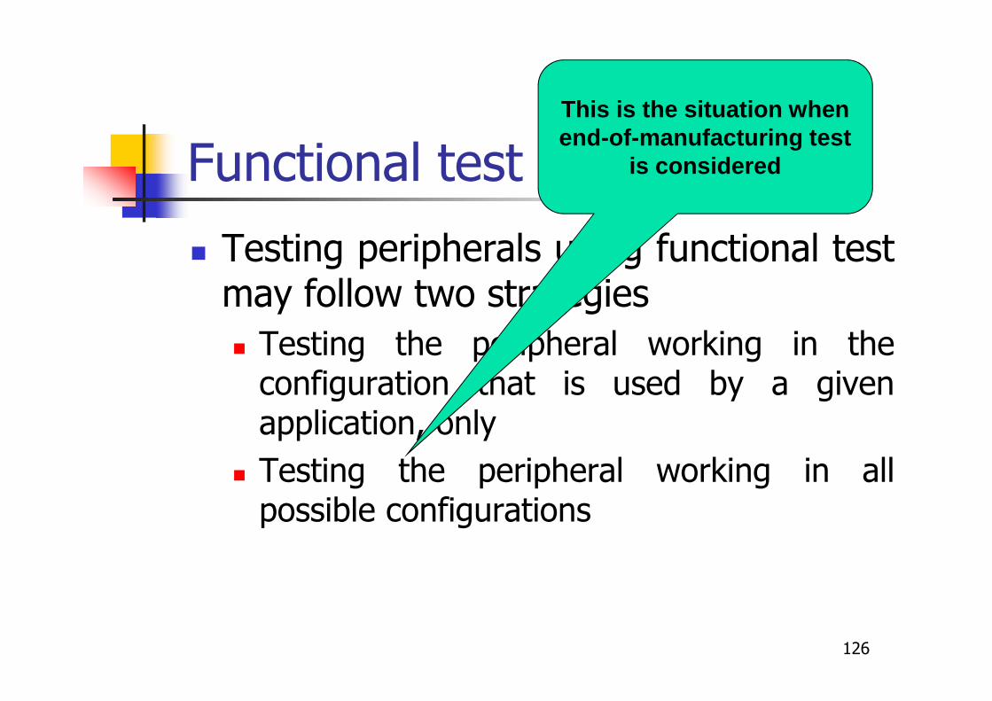
Functional test of peripherals
� Testing peripherals using functional testmay follow two strategies
� Testing the peripheral working in theconfiguration that is used by a givenapplication, only
� Testing the peripheral working in allpossible configurations
This is the situation whenend-of-manufacturing test
is considered
127
Peripheral testing
� It requires
� Configuring the peripheral (configurationcode fragment)
� Exercising the peripheral (functionalfragment, including code and data)
128
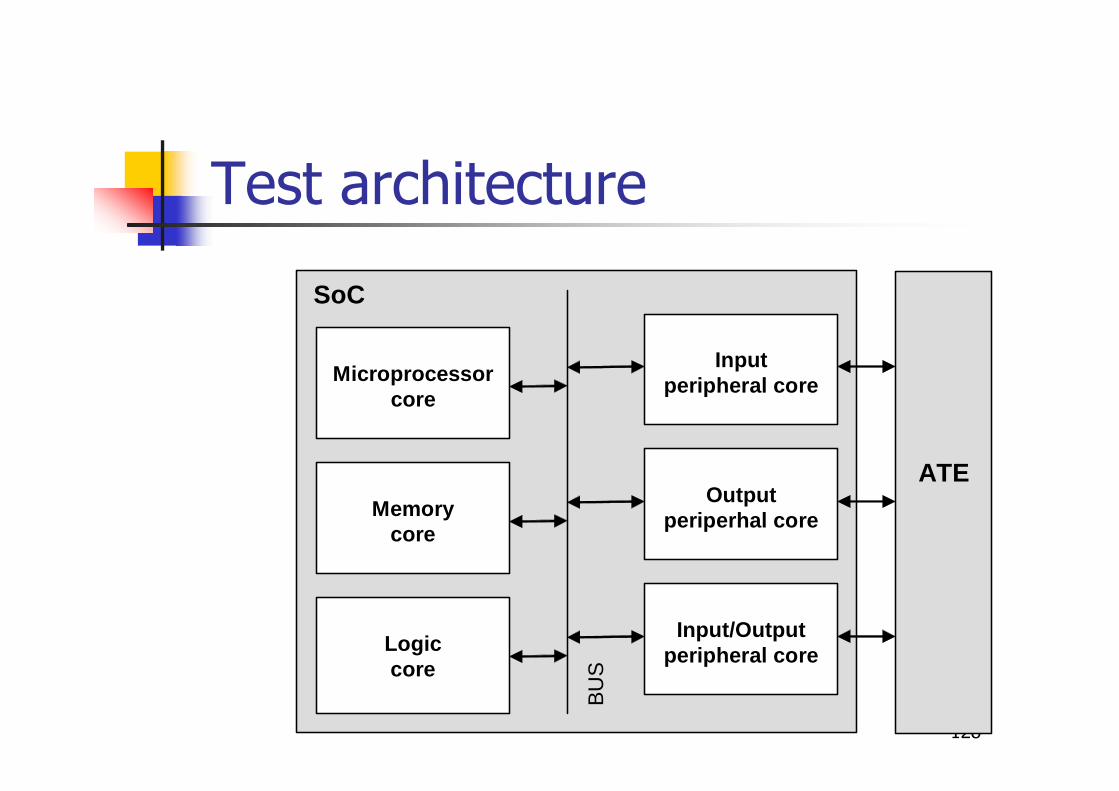
Test architecture
SoC
Microprocessor
core
Memory
core
Input/Output
peripheral core
Output
periperhal core
Input
peripheral core
BU
S
ATE
Logic core

129
Test stimuli generation
� It can be done in different ways:
� Manually or automatically
� Starting from a data-sheet, an RT-leveldescription, a gate-level description
� Suitable metrics are required to guidegeneration (and to stop it)
130
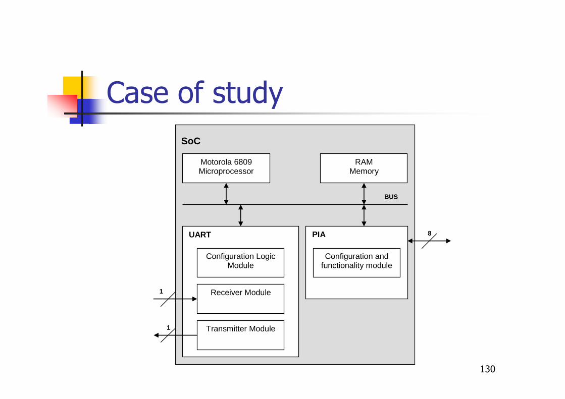
Case of study
UART
Motorola 6809 Microprocessor
RAM Memory
Transmitter Module
Receiver Module
Configuration Logic Module
PIA
SoC
BUS
8
1
1
Configuration and functionality module
131
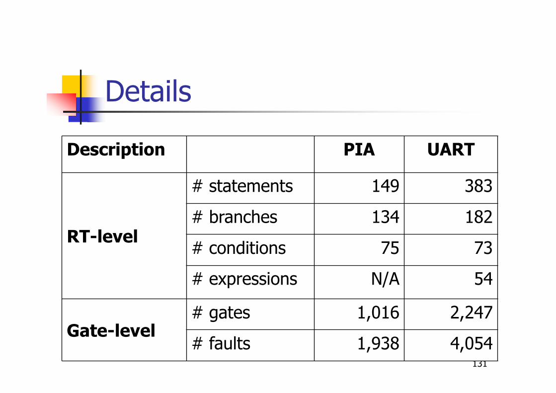
Details
Description PIA UART
RT-level
# statements 149 383
# branches 134 182
# conditions 75 73
# expressions N/A 54
Gate-level# gates 1,016 2,247
# faults 1,938 4,054
132
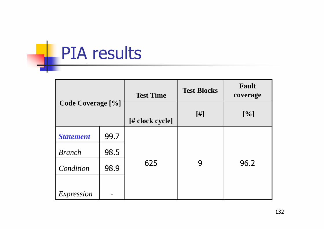
PIA results
Code Coverage [%]Test Time
Test BlocksFault
coverage
[# clock cycle][#] [%]
Statement 99.7
625 9 96.2
Branch 98.5
Condition 98.9
Expression -
133
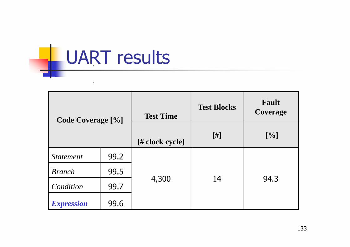
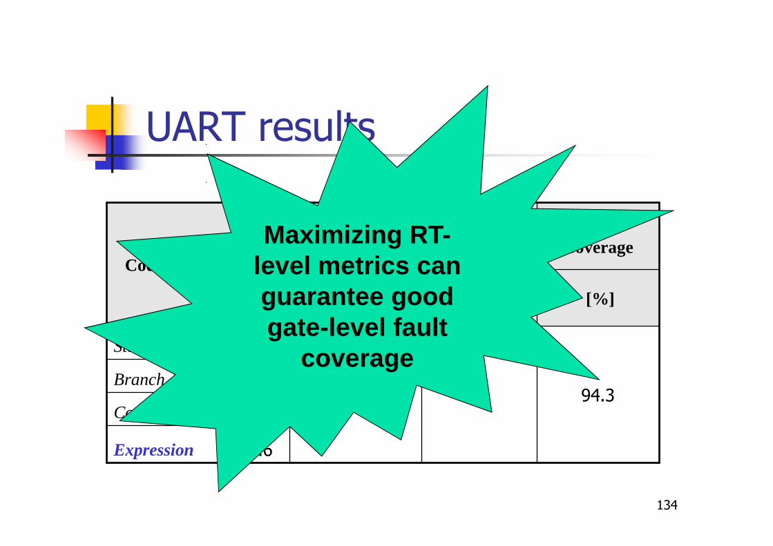
UART results
Code Coverage [%] Test TimeTest Blocks
Fault Coverage
[# clock cycle][#] [%]
Statement 99.2
4,300 14 94.3Branch 99.5
Condition 99.7
Expression 99.6
134
UART results
Code Coverage [%] Test TimeTest Blocks
Fault Coverage
[# clock cycle][#] [%]
Statement 99.2
4,300 14 94.3Branch 99.5
Condition 99.7
Expression 99.6
Maximizing RT-level metrics can guarantee good gate-level fault
coverage
135
Open issues
� Minimizing the test length� Identifying the minimal number of
configurations for test
� Suitably generating the stimuli for eachconfiguration
� Minimizing the external support� Loopback
� Testing asynchronous features (e.g.,arbitration)
136
Testing system peripherals
� System peripheral units (e.g., interruptcontrollers, DMA controllers) are evenmore complex to test because
� During the usage phase, the CPU can notcompletely access to them, but requirespassing through other peripheral modules
� Often do manage asynchronous signals
Grosso et al., JETTA, 2012
137
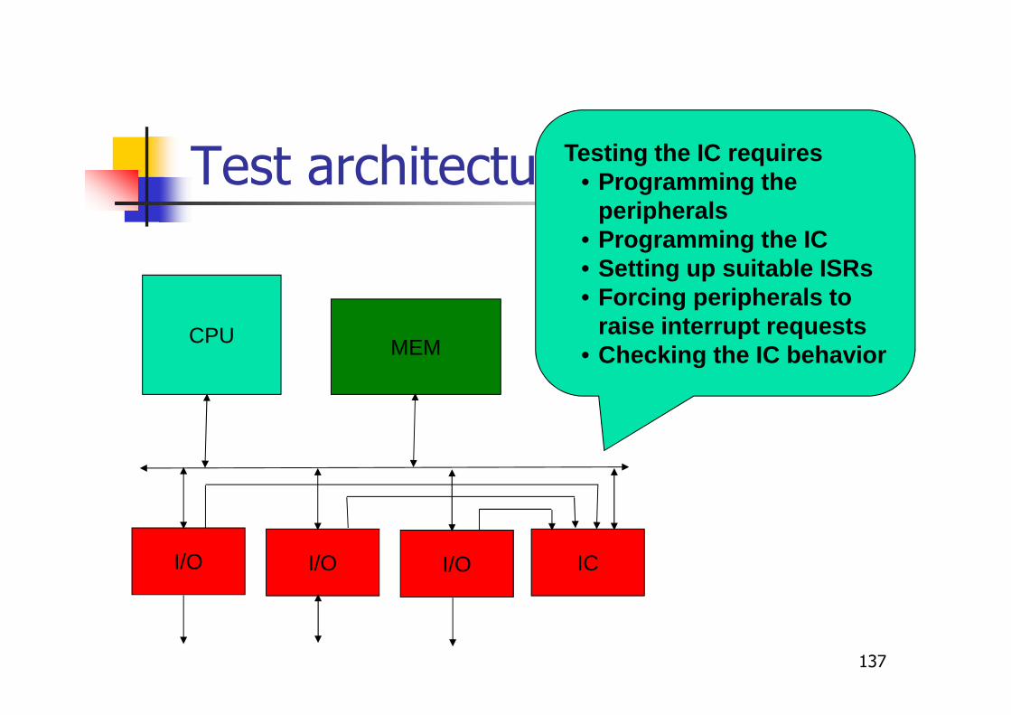
Test architecture
CPU MEM
I/O I/O I/O IC
Testing the IC requires• Programming the
peripherals• Programming the IC• Setting up suitable ISRs• Forcing peripherals to
raise interrupt requests• Checking the IC behavior

138
Summary
� Introduction to test
� Functional test
� Functional test of processors
� Functional test of peripheralcomponents
� In-field test
� Conclusions
139
In-field test
� Functional test can be used for in-fieldtest, too
� Short test procedures can be activatedperiodically, or during idle times
� They must be written in such a waythat they don't interfere with the µPnormal behavior
Paschalis et al., Trans. on CAD, 2005
In-field test & reliability standards
� Some reliability standards define strictrequirements for in-field test targets
� For example, the ISO 26262 standard forautomotive requires the following faultcoverage (for stuck-at and transition faults),depending on the reliability level of theapplication
141
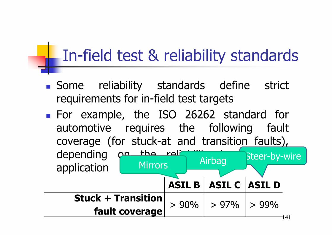
In-field test & reliability standards
� Some reliability standards define strictrequirements for in-field test targets
� For example, the ISO 26262 standard forautomotive requires the following faultcoverage (for stuck-at and transition faults),depending on the reliability level of theapplication
ASIL B ASIL C ASIL D
Stuck + Transition
fault coverage> 90% > 97% > 99%
Steer-by-wireAirbagMirrors
142
In-field test constraints
� When SBST is used for in-field test,several scenarios should be considered
� Test is performed when the system is not(yet) running (e.g., at startup)
� Test is performed while the system isrunning (e.g., during periodical time slots)
Riefert et al., DATE, 2015
143
Test at startup
� In this case� The whole test can be performed until its
end
� The previous context has not to bepreserved and then restored
� The test can access most of the systemfeatures
� Time duration is moderately important
� Test code size is moderately important

144
Test during operation
� In this case the application is interrupted, thetest launched and run for a given period(often short), and then the application isresumed
� This means that
� The whole test has to be split in fragments, eachshort enough to be executed in a test slot; eachfragment should be independent
� The test should minimally interfere with theapplication
� Test duration and code size are very important
Critical units
� Some modules are particularly criticalwhen in-field testing is considered
� Address Calculation Unit
� Branch Prediction Unit
� Exception Unit
� Special techniques are required to maketheir test feasible and effective
145

Address Calculation Unit
� Used by LOAD/STORE instructions
� Embeds a large dedicated adder
� Requires computing addresses spanningthe whole memory
� Its test may conflict with constraintscoming from the application, such as
� The amount of memory for test data andcode
� The position of this memory area 146
Bernardi et al., ETS, 2012
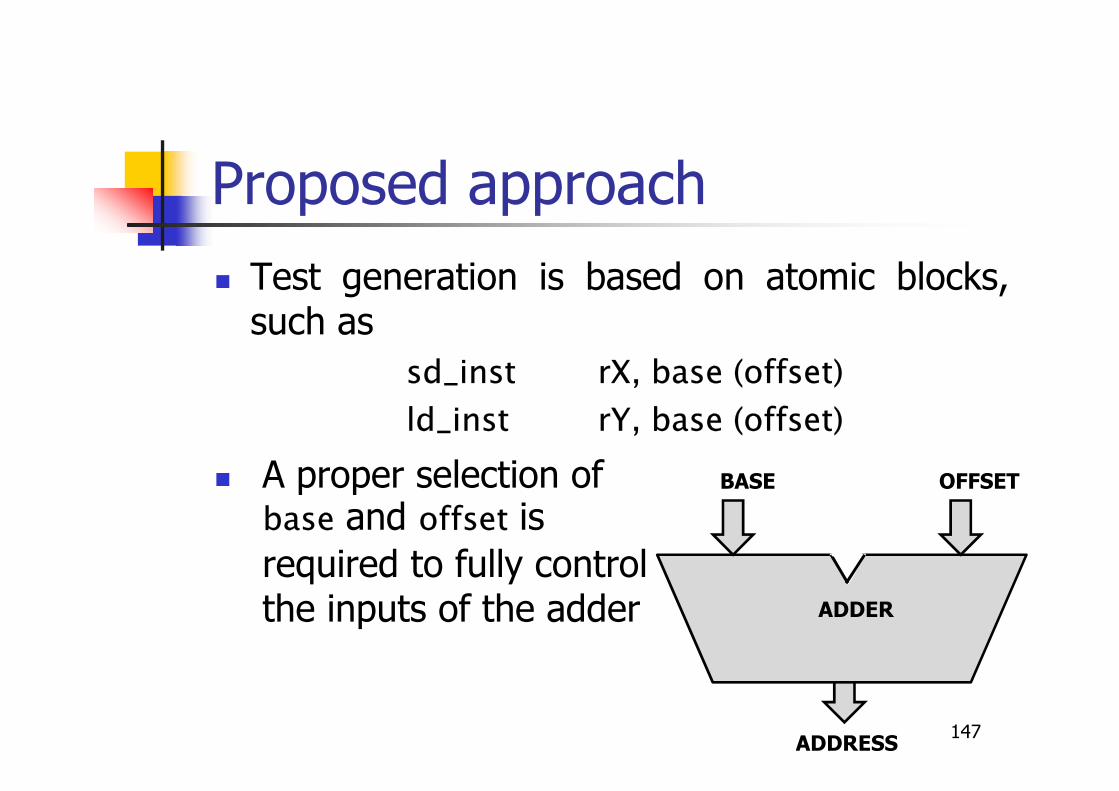
Proposed approach
� Test generation is based on atomic blocks,such as
sd_inst rX, base (offset)
ld_inst rY, base (offset)
� A proper selection of base and offset is
required to fully control the inputs of the adder
147
ADDER
BASE OFFSET
ADDRESS

Some figures
148
Case study GatesSA faults
(#)Self-Testdata size
STM core 689 4,188 2 KB
miniMIPS 342 1,988 2 KB
Self-Testcode size
Exec Time(cc)
Fault Coverage
(%)
1.4 KB 823 95.11
1.6 KB 778 94.27
Some hours of CPUtime were required forgenerating the finaltest program
Functionally untestable faults
� Some faults may be untestable duringthe operational phase
� Examples
� Faults related to scan chains
� Faults related the debug circuitry
� Faults related to the reset circuitry
149
Bernardi et al., DATE, 2013
Functionally untestable faults
� In some cases these faults do not affect thenormal behavior
� Faults in the circuitry used for manufacturing test
� Faults in the debug circuitry
� Faults in unused circuitry
� Their number could be non-negligible
� They may significantly contribute to makedifficult matching the in-field testrequirements
150
Functionally untestable faults
� How can we identify them?
� Commercial ATPG tools do not providethis feature
� Standards and regulations requireproved procedures
� Formal techniques can be used
151
Test program compaction
� Test duration is often an issue, especiallywhen the test is performed during theapplication idle times
� Test programs are often quite long /redundant
� Because they come from legacy code
� Because they have (partly) be generated randomly
� Because compaction has not been addressedduring generation
Approaches
� Static approach
� Compaction is addressed AFTER testprogram generation, e.g., checkingwhether some instructions can be removedwithout reducing the achieved faultcoverage
� Dynamic approach
� Compaction is addressed DURING testprogram generation
Gaudesi et al.,ETS, 2015
154
Conclusions
� Functional test� is required for in-field test and to catch some
defects
� is a hot research topic
� Effective test algorithms can be developed forseveral modules
� Hybrid solutions (combining it with DfT) maybe effective
� Cost-effective test generation is still an openproblem
� Test program compaction is often an issue

Questions?
155