Full Line Catalog - MEAD-USAmead-usa.com/products/media/mead2015.pdf · 1# Reference Index...
72
• Actuators • Valves • Production Devices • Safety Setting a new standard for: Full Line Catalog Mead Fluid Dynamics Full Line Catalog Catalog
Transcript of Full Line Catalog - MEAD-USAmead-usa.com/products/media/mead2015.pdf · 1# Reference Index...
• Actuators
• Valves
• Production Devices
• Safety
Setting a new standard for:
Full Line Catalog
Mead
FluidDynam
icsFullLineCatalog
Bim
baManufacturing
Com
panyMEA
D-FL-515
Your stocking distributor is:
Worldwide distribution means there is a professional stocking
Bimba distributor nearby ready to service your needs.
Catalog
Bimba Manufacturing Headquarters
P.O. Box 68 Monee, Illinois 60449-0068
Phone: 708-534-8544 Toll Free: 800-44-BIMBA Fax: 708-235-2014
Email: [email protected] www.bimba.com
PNEUMATIC • ELECTRIC • HYDRAULIC ACTUATORS FITTINGS — MANIFOLDS — VALVES — AIR PREPARATION — SAFETY & PRODUCTION
BIMBA BRANDS I ACRO I MEAD I MFD I PNEUMADYNE I TRD
Mead Fluid Dynamics
4114 North Knox Avenue Chicago, IL 60641
Phone: 773-685-6800 Toll Free: 877-MEAD-USA Fax: 773-685-7002
Email: [email protected] www.mead-usa.com
© Copyright 2015 Bimba Manufacturing Company. MEAD-FL-515 Effective May 2015. All Rights Reserved.
Table of Contents
1-3 Reference
1 Cylinder Finder2-3 Valve Finder
4-25 Control Valves
4 Isonic®
5-6 Isonic® V1000 Series7-9 Isonic® V2000 Series10-11 Isonic® V4000 Series12 Manifold PowerStrip™
13 Isonic® Accessories14-15 Nova16-17 Capsula18 Dura-Matic 4-Way Valves19 Ergonomic Low Stress Air Valve20-21 LTV22-23 MV 3-Way Switches24-25 Cam, Foot, Hand and Button Valves
26-50 Cylinders
26-27 Small Bore Tie Rod28-33 DM1 & DM2 NFPA Interchangeable34-41 HD1 NFPA Heavy-Duty42-43 Large Bore HD NFPA Heavy Duty44-45 Centaur46 Proximity Switches (Reed/Solid State)47 Space Saver48-49 Miniature Air Cylinders50 Single-Acting Air Clamps
51-57 Specialty Valves
51 Lockout and Easy-Glide Ball Handle Valves52 Mini Solenoid and Binary Valves53 Air Timers and Impulse Relay Valves54 Stroke Sensors and Air to Electric Switches55 Dash/Panel Mount Control Valves56 Dyla-Trol® Flow Controls57 Two-Hand Control Valves
58-61 Production Devices
58 Air Presses59 Heavy Multi-Stage Press60 Air Press Dimensions61 Air Tools
62-63 Accessories
62 RAF & RAFK: Right Angle Flow Controls62 Female DIN Solenoid Connectors62 Manifold63 Quick Exhaust Valves63 Shuttle Valves63 Check Valves63 Air Silencers & Breathers
64-68 Index
64 Custom Products65-66 Product Index67-68 Notes
Mead Fluid Dynamics, Inc.Mead USA
4114 N. Knox Ave.Chicago, IL 60641Phone: (773) 685-6800Fax: (773) 685-7002Customer Service Toll Free Number:(877) MEAD USA (877-632-3872)[email protected]
Visit www.mead-usa.com for downloadable:• PDF Files• CAD Drawings• Exploded Views
www.mead-usa.com #1
Reference
Inde
xAc
cess
ories
Prod
uctio
nDe
vices
Spec
ialty
Valve
sCy
linde
rsCo
ntrolV
alves
Referenc
e
Foot BottomFlush
Nose Frt/RearFlush
FrontFlange
RearFlange
Pivot Clevis FrontTrunnion
RearTrunnion
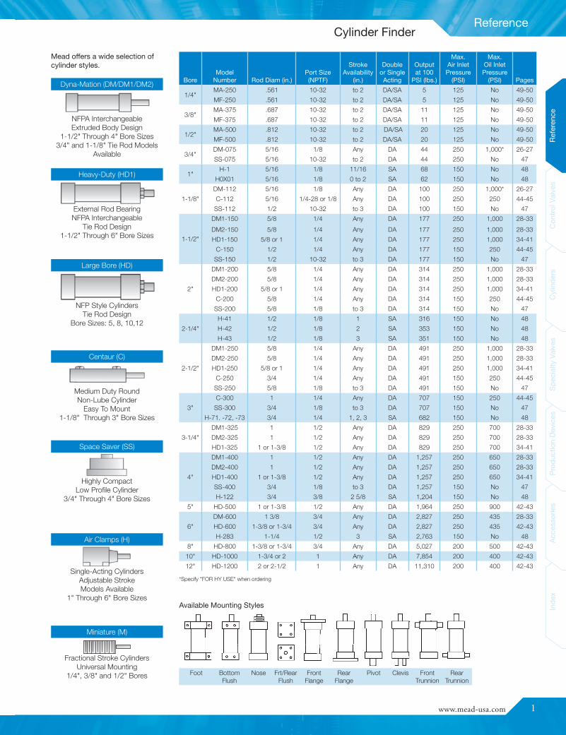
NFPA InterchangeableExtruded Body Design
1-1/2" Through 4" Bore Sizes3/4" and 1-1/8" Tie Rod Models
Available
BoreModel
Number Rod Diam (in.)Port Size(NPTF)
StrokeAvailability
(in.)
Doubleor SingleActing
Outputat 100
PSI (lbs.)
Max.Air InletPressure
(PSI)
Max.Oil InletPressure
(PSI) Pages
1/4"MA-250 .561 10-32 to 2 DA/SA 5 125 No 49-50
MF-250 .561 10-32 to 2 DA/SA 5 125 No 49-50
3/8"MA-375 .687 10-32 to 2 DA/SA 11 125 No 49-50
MF-375 .687 10-32 to 2 DA/SA 11 125 No 49-50
1/2"MA-500 .812 10-32 to 2 DA/SA 20 125 No 49-50
MF-500 .812 10-32 to 2 DA/SA 20 125 No 49-50
3/4"DM-075 5/16 1/8 Any DA 44 250 1,000* 26-27
SS-075 5/16 10-32 to 2 DA 44 250 No 47
1"H-1 5/16 1/8 11/16 SA 68 150 No 48
H0X01 5/16 1/8 0 to 2 SA 62 150 No 48
1-1/8"
DM-112 5/16 1/8 Any DA 100 250 1,000* 26-27
C-112 5/16 1/4-28 or 1/8 Any DA 100 250 250 44-45
SS-112 1/2 10-32 to 3 DA 100 150 No 47
1-1/2"
DM1-150 5/8 1/4 Any DA 177 250 1,000 28-33
DM2-150 5/8 1/4 Any DA 177 250 1,000 28-33
HD1-150 5/8 or 1 1/4 Any DA 177 250 1,000 34-41
C-150 1/2 1/4 Any DA 177 150 250 44-45
SS-150 1/2 10-32 to 3 DA 177 150 No 47
2"
DM1-200 5/8 1/4 Any DA 314 250 1,000 28-33
DM2-200 5/8 1/4 Any DA 314 250 1,000 28-33
HD1-200 5/8 or 1 1/4 Any DA 314 250 1,000 34-41
C-200 5/8 1/4 Any DA 314 150 250 44-45
SS-200 5/8 1/8 to 3 DA 314 150 No 47
2-1/4"
H-41 1/2 1/8 1 SA 316 150 No 48
H-42 1/2 1/8 2 SA 353 150 No 48
H-43 1/2 1/8 3 SA 351 150 No 48
2-1/2"
DM1-250 5/8 1/4 Any DA 491 250 1,000 28-33
DM2-250 5/8 1/4 Any DA 491 250 1,000 28-33
HD1-250 5/8 or 1 1/4 Any DA 491 250 1,000 34-41
C-250 3/4 1/4 Any DA 491 150 250 44-45
SS-250 5/8 1/8 to 3 DA 491 150 No 47
3"
C-300 1 1/4 Any DA 707 150 250 44-45
SS-300 3/4 1/8 to 3 DA 707 150 No 47
H-71. -72, -73 3/4 1/4 1, 2, 3 SA 682 150 No 48
3-1/4"
DM1-325 1 1/2 Any DA 829 250 700 28-33
DM2-325 1 1/2 Any DA 829 250 700 28-33
HD1-325 1 or 1-3/8 1/2 Any DA 829 250 700 34-41
4"
DM1-400 1 1/2 Any DA 1,257 250 650 28-33
DM2-400 1 1/2 Any DA 1,257 250 650 28-33
HD1-400 1 or 1-3/8 1/2 Any DA 1,257 250 650 34-41
SS-400 3/4 1/8 to 3 DA 1,257 150 No 47
H-122 3/4 3/8 2 5/8 SA 1,204 150 No 48
5" HD-500 1 or 1-3/8 1/2 Any DA 1,964 250 900 42-43
6"
DM-600 1 3/8 3/4 Any DA 2,827 250 435 28-33
HD-600 1-3/8 or 1-3/4 3/4 Any DA 2,827 250 435 42-43
H-283 1-1/4 1/2 3 SA 2,763 150 No 48
8" HD-800 1-3/8 or 1-3/4 3/4 Any DA 5,027 200 500 42-43
10" HD-1000 1-3/4 or 2 1 Any DA 7,854 200 400 42-43
12" HD-1200 2 or 2-1/2 1 Any DA 11,310 200 400 42-43
Dyna-Mation (DM/DM1/DM2)
Heavy-Duty (HD1)
Large Bore (HD)
Miniature (M)
Air Clamps (H)
Space Saver (SS)
Centaur (C)
*Specify "FOR HY USE" when ordering
Mead offers a wide selection ofcylinder styles.
External Rod BearingNFPA Interchangeable
Tie Rod Design1-1/2" Through 6" Bore Sizes
NFP Style CylindersTie Rod Design
Bore Sizes: 5, 8, 10,12
Medium Duty RoundNon-Lube Cylinder
Easy To Mount1-1/8" Through 3" Bore Sizes
Highly CompactLow Profile Cylinder
3/4" Through 4" Bore Sizes
Single-Acting CylindersAdjustable StrokeModels Available
1" Through 6" Bore Sizes
Fractional Stroke CylindersUniversal Mounting
1/4", 3/8" and 1/2" Bores
Available Mounting Styles
Cylinder Finder

2
Reference
ReferenceControlValves
CylindersSpecialtyValves
ProductionDevices
AccessoriesIndex
ReferenceControlValves
CylindersSpecialtyValves
ProductionDevices
AccessoriesIndex
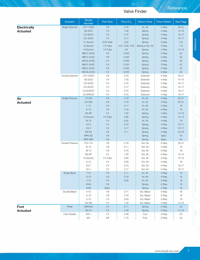
Actuator Model Number Port Size Flow (Cv) Return Flow Flow Pattern See Page
Straight Plunger MV-5 1/8 0.11 Spring 3-Way 22-23
MV-45 1/8 0.11 Spring 3-Way 22-23
LTV-5 1/8 0.18 Int. Air 4-Way 20-21
LTV-45 1/8 0.18 Int. Air 4-Way 20-21
FC-51 1/8 0.81 Spring 3-Way 25
3C-1 1/4 0.48 Spring 3-Way 25
FC-101 3/8 1.15 Spring 3-Way 24
Straight Leaf MV-10 1/8 0.11 Spring 3-Way 22-23
MV-70 1/8 0.11 Spring 3-Way 22-23
LTV-10 1/8 0.18 Int. Air 4-Way 20-21
Roller MV-15 1/8 0.11 Spring 3-Way 22-23
MV-90 1/8 0.11 Spring 3-Way 22-23
MV-25, MV-30 1/8 0.11 Spring 3-Way 22-23
MV-75 1/8 0.11 Spring 3-Way 22-23
LTV-15 1/8 0.18 Int. Air 4-Way 20-21
LTV-25, LTV-30 1/8 0.18 Int. Air 4-Way 20-21
LTV-75 1/8 0.18 Int. Air 4-Way 20-21
One-Way Roller MV-20 1/8 0.11 Spring 3-Way 22-23
MV-80 1/8 0.11 Spring 3-Way 22-23
LTV-20 1/8 0.18 Int. Air 4-Way 20-21
LTV-80 1/8 0.18 Int. Air 4-Way 20-21
Extended Rod MV-85 1/8 0.11 Spring 3-Way 22-23
LTV-85 1/8 0.18 Int. Air 4-Way 20-21
Ball MV-40 1/8 0.11 Spring 3-Way 22-23
LTV-40 1/8 0.18 Int. Air 4-Way 20-21
Fingertip Lever MV-50 1/8 0.11 Spring 3-Way 22-23
LTV-50 1/8 0.18 Int. Air 4-Way 20-21
N2-HL 1/4 1.00 Spring 4-Way 14-15
FT-101 3/8 1.15 Spring 3-Way 24
FT-4 1/8 0.16 Spring 4-Way 24
Low Stress LTV-PBG(F) 1/8 0.18 Int. Air 3- or 4-Way 19
Straight Lever C2-7 1/4 0.75 Spring 4-Way 16-17
C5-7 1/2 3.17 Spring 4-Way 16-17
C2-8 1/4 0.75 Hand 4-Way 16-17
C5-8 1/2 3.17 Hand 4-Way 16-17
4B-1 1/4 0.48 Hand 4-Way 25
Push Button &Palm
MV-140 1/8 0.11 Spring 3-Way 22-23
LTV-125 1/8 0.18 Int. Air 4-Way 20-21
LTV-140 1/8 0.18 Int. Air 4-Way 20-21
PC-51 1/8 0.81 Spring 3-Way 25
MV-MH 1/8 0.11 Spring 3-Way 22-23
LTV-MH 1/8 0.18 Int. Air 4-Way 20-21
MV-EH & MV-FH 1/8 0.11 Spring 3-Way 22-23
LTV-EH & LTV-FH 1/8 0.18 Int. Air 4-Way 20-21
MV-ES 1/8 0.11 Spring 3-Way 22-23
MV-EMS 1/8 0.18 Detent 3-Way 22-23
LTV-ES 1/8 0.18 Int. Air 4-Way 20-21
Double Button N2-PB 1/4 1.00 Button 4-Way 14-15
Knob (Push-Pull) LTV-130 1/8 0.18 Knob 4-Way 20-21
PC-51A 1/8 0.81 Knob 3-Way 25
ACV-16 5/32 0.053 Knob 4-Way 55
ACV-25 1/4 0.12 Knob 4-Way 55
Flip Toggle MV-35 1/8 0.11 Toggle 3-Way 22-23
LTV-35 1/8 0.18 Toggle 4-Way 20-21
Twist (2 Pos.) MV-TP 1/8 0.11 Twist 3-Way 22-23
LTV-TP 1/8 0.18 Twist 4-Way 20-21
MechanicallyActuated
Hand (Manually)Actuated
Valve Finder
www.mead-usa.com #3
Reference
Inde
xAc
cess
ories
Prod
uctio
nDe
vices
Spec
ialty
Valve
sCy
linde
rsCo
ntrolV
alves
Referenc
e
ActuatorModel
NumberPort Size Flow (Cv) Return Flow Flow Pattern See Page
Single Solenoid LTV-115DD 1/8 0.18 Int. Air 4-Way 20-21
N2-SCD 1/4 1.00 Spring 4-Way 14-15
C2-4DCD 1/4 0.75 Spring 4-Way 16-17
C5-4DCD 1/2 3.17 Spring 4-Way 16-17
V1 (Isonic) 5/32 Tube 0.02 Spring 3-Way 4-6
V2 (Isonic) 1/4 Tube 0.01, 0.02, 0.05 Spring or Ext. Air 3-Way 7-9
V4 (Isonic) 1/4 Tube 0.8 Spring 4-Way 10-13
MB12-3CSC 1/8 0.035 Spring 3-Way 52
MB12-3USC 1/8 0.035 Spring 3-Way 52
MC25-3CSC 1/4 0.035 Spring 3-Way 52
MB12-3USC 1/4 0.035 Spring 3-Way 52
MB12-2CSC 1/8 0.035 Spring 2-Way 52
MC25-2CSC 1/4 0.035 Spring 2-Way 52
Double Solenoid LTV-120DD 1/8 0.18 Solenoid 4-Way 20-21
N2-DCD 1/4 1.00 Solenoid 4-Way 14-15
C2-5DCD 1/4 0.75 Solenoid 4-Way 16-17
C5-5DCD 1/2 3.17 Solenoid 4-Way 16-17
C2-6HDCD 1/4 0.75 Solenoid 4-Way 16-17
C2-6RDCD 1/4 0.75 Solenoid 4-Way 16-17
Single Pressure LTV-60 1/8 0.18 Int. Air 4-Way 20-21
LTV-60L 1/8 0.18 Int. Air 4-Way 20-21
L-10 1/8 0.11 Int. Air 4-Way 18
K-10 1/8 0.18 Int. Air 4-Way 18
N2-SP 1/4 1.00 Spring 4-Way 14-15
V4 (Isonic) 1/4 Tube 0.80 Spring 4-Way 10-13
W-10 1/4 0.63 Int. Air 4-Way 18
C2-3 1/4 0.75 Spring 4-Way 16-17
C5-3 1/2 3.17 Spring 4-Way 16-17
MV-60 1/8 0.11 Spring 3-Way 22-23
MPE-BZ 1/8 - Spring Spec. 54
MPE-BZE 1/8 - Spring Spec. 54
Double Pressure LTV-110 1/8 0.18 Ext. Air 4-Way 20-21
N-10 1/8 0.11 Ext. Air 4-Way 18
M-10 1/8 0.18 Ext. Air 4-Way 18
N2-DP 1/4 1.00 Ext. Air 4-Way 14-15
V4 (Isonic) 1/4 Tube 0.80 Ext. Air 4-Way 10-13
X-10 1/4 0.63 Ext. Air 4-Way 18
C2-1 1/4 0.75 Ext. Air 4-Way 16-17
C5-1 1/2 3.17 Ext. Air 4-Way 16-17
Single Bleed T-10 1/8 0.11 Int. Air 4-Way 18
O-10 1/8 0.18 Int. Air 4-Way 18
Y-10 1/4 0.63 Int. Air 4-Way 18
404A 1/8 - Spring 2-Way 18
405A Spec. - Spring 2-Way 18
Double Bleed V-10 1/8 0.11 Ext. Bleed 4-Way 18
U-10 1/8 0.18 Ext. Bleed 4-Way 18
Z-10 1/4 0.63 Ext. Bleed 4-Way 18
N2-DB 1/4 1.00 Ext. Bleed 4-Way 14-15
Pedal 2060400 1/4 0.11 Spring 3-Way 23
N2-F4 1/4 1.00 Spring 4-Way 14-15
Foot Treadle 4W-1 1/4 0.48 Foot 4-Way 25
201 3/8 1.15 Foot 3-Way 24
ElectricallyActuated
AirActuated
FootActuated
Valve Finder

4
Control Valves
ReferenceControlValves
CylindersSpecialtyValves
ProductionDevices
AccessoriesIndex
Design Optimizes Valve PerformanceIsonic® 2, 3 and 4-way valves feature a unique, multi-patented designthat significantly shrinks valve size while boosting flow capacity. Withits design and a state-of-the-art manufacturing process, Isonic®
breaks through the restriction and limitations of conventional valvemanufacturing.
Revolutionary Valve Production
The Award-Winning “Half-Shell” Design
Maximum Air Flow
Faster Manifold Connections
Quick-Connect Collets - No Fittings NeededWith its unique design Isonic® eliminates the need for tube fittings.Built-in, push-to-connect collets allow for fast and easy tube andmanifold connections.
Resistant To Harsh ConditionsMolded from a high performance thermoplastic, Isonic® achievessuperior heat, impact and chemical resistance. It is listed with both ULand CSA.
Loaded with Standard FeaturesAlong with its size and price advantages, Isonic® offers numeroususer features, many of them standard. Most models feature anintegral electronic board with surge suppression and LED. A variety ofvoltages and wiring options are available. This combination of priceand versatility makes Isonic® the perfect control choice for pneumaticsystems.
Instead of the angular passages of most conventional valves, Isonic’sinternal channels are aerodynamically shaped for maximum air flow andminimal internal friction. Eliminating sharp corners and abrupt changesin direction reduces air turbulence and energy loss. Normally round airpassages are replaced by thin, deep, tape-like channels that conservespace and optimize air flow.
Isonic® is a registered trademark of Mead Fluid Dynamics, Inc.
Isonic® V1 and V4 have earned ULrecognition and have been tested to thestandards of CSA and conforms to theapplicable directives of the European Union.
V1000 Series2 & 3 way
V2000 Series2 & 3 way
V4000 Series4 way
The heart of the Isonic® concept is its patented “half-shell” design.Composed of two mirror-image halves, Isonic® allows its flowchannels and internal component compartments to be designeddirectly into these molded body sections. Valve bodies are molded ofhigh-strength, glass-impregnated Ultem thermoplastic.
Assembly is achieved by simply inserting the various valve elementsinto their corresponding “half-shell” pockets. Internal componentsare easily positioned to make optimal use of space.
The valve is completed by ultrasonically welding the two valvesegments, creating a strong bond and hermetic seal. This designtotally eliminates the need for fasteners, adhesives, gaskets andinserts.
Isonic® technology eliminates all machining operations associatedwith valve manufacturing. Requiring only simple assembly, Isonic®
can be produced quickly and easily with significant cost reduction.
The Isonic® manifold system has been designed to virtually eliminatedowntime, eliminating all end plates, screws, o-rings and gasketscustomarily found in manifold systems. Connecting any valve tothe manifold base is as easy as plugging in an electrical cord. Withthis patented “plug-in” design, replacing an individual valve can beaccomplished in seconds, without the aid of any tools!
Available in two, three, four or five station segments, the Isonic®
manifold’s unique modular design creates a versatile, expandablecontrol base. For larger manifolds, two or more segments can be easilycombined to fulfill any needs. Further, manifold segments are easilyisolated for applications with differential pressures.
Isonic®

www.mead-usa.com #5
Control Valves
Spec
ialty
Valve
sProd
uctio
nDe
vices
Acce
ssories
Inde
xCy
linde
rsCo
ntrolV
alves
Referenc
eInde
xAc
cess
ories
Prod
uctio
nDe
vices
Spec
ialty
Valve
sCy
linde
rsCo
ntrolV
alves
Referenc
e
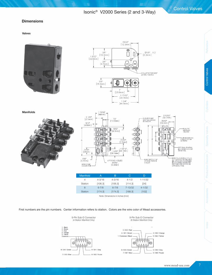
Dimensions Accessories
P1Q1NOTE: One (1) pc. is included with each ”W” type valve. 24
AWG wire.
MM-019Muffler shown here on V1 Valve with T1 option
Manifold
Common Air Inlet: Built-in, push-in fittings for 1/4" OD or 6mm tubingboth ends
Foot Mounting: 4 slots, 11/16" diameterDIN Rail Mounting: Attaches to 15mm DIN rail
SpecificationsDesign: Poppet
Media: Air or Inert Gas
Lubrication: None Required
Filtration: 40 Micron
Cycle Life: 50,000,000 cycles
Orifice Size: A: 0.025" / 0.65mmB: 0.035" / 0.90mmC: 0.055" / 1.4mm
Flow: A: 0.01 Cv
B: 0.02 Cv
C: 0.05 Cv
Maximum Pressure: A: 120 PSI / 8.3 BarB: 120 PSI / 8.3 BarC: 30 PSI / 2.1 Bar
Vacuum: to 28 in. Hg
Temperature Range: 0° F to 120° F (-18° C to 49° C)
Tubing: 5/32" or 4mm
Mounting Holes: 0.156 diameter (1 hole, 1 slot)
Seals: Viton® and Nitrile
Weight: 1.5 oz. (per valve)
Voltage 12DC 24DC 24AC 120ACAmps 0.133 0.058 0.058 0.014
Resistance 92Ω 406Ω 406Ω 8350Ω
Initial Power 1.6 1.4 1.4 1.7
Continuous On 1.3 1.2 1.2 1.5
Response Time: 10 milliseconds
Molex Connector: UL and CSA ListedDin Connector: Protection Class- IP 65 according to DIN 40 050
Insulation Class- Group C according to VDE 0110Conform to DIN 43650 Form C Specifications
2/2 NC
Valve Symbols:
3/2 NC
P1SA1
P1SA2
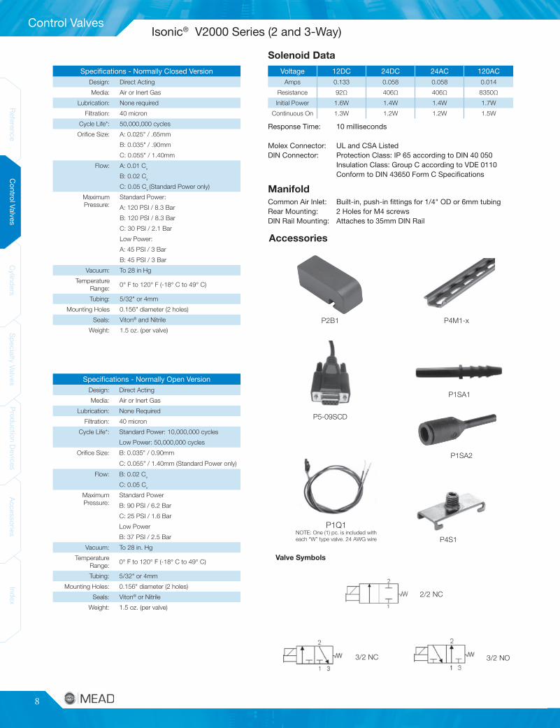
Solenoid Data
Isonic® V1000 Series (2 and 3-Way)
Manifolds:
Valves:
6
Control Valves
ReferenceControlValves
CylindersSpecialtyValves
ProductionDevices
AccessoriesIndex
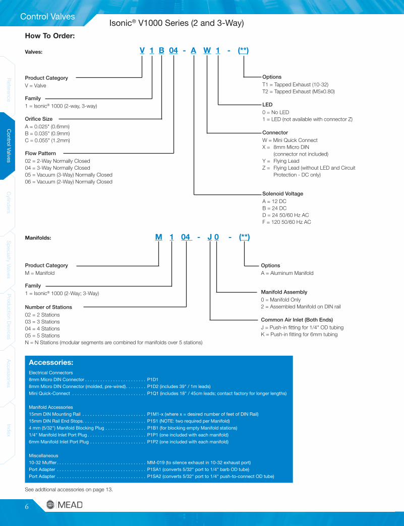
Electrical Connectors8mm Micro DIN Connector . . . . . . . . . . . . . . . . . . . . . . . . P1D18mm Micro DIN Connector (molded, pre-wired). . . . . . . . P1D2 (includes 39" / 1m leads)Mini Quick-Connect . . . . . . . . . . . . . . . . . . . . . . . . . . . . . P1Q1 (includes 18" / 45cm leads; contact factory for longer lengths)
Manifold Accessories15mm DIN Mounting Rail . . . . . . . . . . . . . . . . . . . . . . . . . P1M1-x (where x = desired number of feet of DIN Rail)15mm DIN Rail End Stops. . . . . . . . . . . . . . . . . . . . . . . . . P1S1 (NOTE: two required per Manifold)4 mm (5/32") Manifold Blocking Plug . . . . . . . . . . . . . . . . P1B1 (for blocking empty Manifold stations)1/4" Manifold Inlet Port Plug . . . . . . . . . . . . . . . . . . . . . . . P1P1 (one included with each manifold)6mm Manifold Inlet Port Plug . . . . . . . . . . . . . . . . . . . . . . P1P2 (one included with each manifold)
Miscellaneous10-32 Muffler . . . . . . . . . . . . . . . . . . . . . . . . . . . . . . . . . . . MM-019 (to silence exhaust in 10-32 exhaust port)Port Adapter . . . . . . . . . . . . . . . . . . . . . . . . . . . . . . . . . . . P1SA1 (converts 5/32" port to 1/4" barb OD tube)Port Adapter . . . . . . . . . . . . . . . . . . . . . . . . . . . . . . . . . . . P1SA2 (converts 5/32" port to 1/4" push-to-connect OD tube)
Accessories:
V 1 B 04 - A W 1 - (**)
Product CategoryV = Valve
Family1 = Isonic® 1000 (2-way, 3-way)
Orifice SizeA = 0.025" (0.6mm)B = 0.035" (0.9mm)C = 0.055" (1.2mm)
Flow Pattern02 = 2-Way Normally Closed04 = 3-Way Normally Closed05 = Vacuum (3-Way) Normally Closed06 = Vacuum (2-Way) Normally Closed
OptionsT1 = Tapped Exhaust (10-32)T2 = Tapped Exhaust (M5x0.80)
LED0 = No LED1 = LED (not available with connector Z)
ConnectorW = Mini Quick ConnectX = 8mm Micro DIN
(connector not included)Y = Flying LeadZ = Flying Lead (without LED and Circuit
Protection - DC only)
Solenoid VoltageA = 12 DCB = 24 DCD = 24 50/60 Hz ACF = 120 50/60 Hz AC
Product CategoryM = Manifold
Family1 = Isonic® 1000 (2-Way; 3-Way)
Number of Stations02 = 2 Stations03 = 3 Stations04 = 4 Stations05 = 5 StationsN = N Stations (modular segments are combined for manifolds over 5 stations)
OptionsA = Aluminum Manifold
Manifold Assembly0 = Manifold Only2 = Assembled Manifold on DIN rail
Common Air Inlet (Both Ends)J = Push-in fitting for 1/4" OD tubingK = Push-in fitting for 6mm tubing
M 1 04 - J 0 - (**)
See addtional accessories on page 13.
Manifolds:
Valves:
How To Order:
Isonic® V1000 Series (2 and 3-Way)
www.mead-usa.com #7
Control Valves
Spec
ialty
Valve
sProd
uctio
nDe
vices
Acce
ssories
Inde
xCy
linde
rsCo
ntrolV
alves
Referenc
eInde
xAc
cess
ories
Prod
uctio
nDe
vices
Spec
ialty
Valve
sCy
linde
rsCo
ntrolV
alves
Referenc
e
Manifold A B C D4 4-3/16 4-3/16 4-1/2 1-11/32
Station [106.3] [106.3] [114.3] [34]
8 6-7/8 6-7/8 7-13/32 4-1/32
Station [174.3] [174.3] [188.3] [102]
Dimensions
Valves
Manifolds
First numbers are the pin numbers. Center information refers to station. Colors are the wire color of Mead accessories.
Note: Dimensions in inches [mm]
9-Pin Sub-D Connector(4 Station Manifold Only)
9-Pin Sub-D Connector(8 Station Manifold Only)
Isonic® V2000 Series (2 and 3-Way)
8
Control Valves
ReferenceControlValves
CylindersSpecialtyValves
ProductionDevices
AccessoriesIndex
Voltage 12DC 24DC 24AC 120ACAmps 0.133 0.058 0.058 0.014
Resistance 92Ω 406Ω 406Ω 8350Ω
Initial Power 1.6W 1.4W 1.4W 1.7W
Continuous On 1.3W 1.2W 1.2W 1.5W
Valve Symbols
Accessories
P1Q1NOTE: One (1) pc. is included witheach “W” type valve. 24 AWG wire
P2B1 P4M1-x
P5-09SCD
P1SA1
P1SA2
P4S1
Specifications - Normally Closed VersionDesign: Direct Acting
Media: Air or Inert Gas
Lubrication: None required
Filtration: 40 micron
Cycle Life*: 50,000,000 cycles
Orifice Size: A: 0.025" / .65mm
B: 0.035" / .90mm
C: 0.055" / 1.40mm
Flow: A: 0.01 Cv
B: 0.02 Cv
C: 0.05 Cv (Standard Power only)
MaximumPressure:
Standard Power:
A: 120 PSI / 8.3 Bar
B: 120 PSI / 8.3 Bar
C: 30 PSI / 2.1 Bar
Low Power:
A: 45 PSI / 3 Bar
B: 45 PSI / 3 Bar
Vacuum: To 28 in Hg
TemperatureRange:
0° F to 120° F (-18° C to 49° C)
Tubing: 5/32" or 4mm
Mounting Holes 0.156" diameter (2 holes)
Seals: Viton® and Nitrile
Weight: 1.5 oz. (per valve)
Specifications - Normally Open VersionDesign: Direct Acting
Media: Air or Inert Gas
Lubrication: None Required
Filtration: 40 micron
Cycle Life*: Standard Power: 10,000,000 cycles
Low Power: 50,000,000 cycles
Orifice Size: B: 0.035" / 0.90mm
C: 0.055" / 1.40mm (Standard Power only)
Flow: B: 0.02 Cv
C: 0.05 Cv
MaximumPressure:
Standard Power
B: 90 PSI / 6.2 Bar
C: 25 PSI / 1.6 Bar
Low Power
B: 37 PSI / 2.5 Bar
Vacuum: To 28 in. Hg
TemperatureRange:
0° F to 120° F (-18° C to 49° C)
Tubing: 5/32" or 4mm
Mounting Holes: 0.156" diameter (2 holes)
Seals: Viton® or Nitrile
Weight: 1.5 oz. (per valve)
Response Time: 10 milliseconds
Molex Connector: UL and CSA ListedDIN Connector: Protection Class: IP 65 according to DIN 40 050
Insulation Class: Group C according to VDE 0110Conform to DIN 43650 Form C Specifications
ManifoldCommon Air Inlet: Built-in, push-in fittings for 1/4" OD or 6mm tubingRear Mounting: 2 Holes for M4 screwsDIN Rail Mounting: Attaches to 35mm DIN Rail
2/2 NC
3/2 NC 3/2 NO
Isonic® V2000 Series (2 and 3-Way)Solenoid Data
www.mead-usa.com #9
Control Valves
Spec
ialty
Valve
sProd
uctio
nDe
vices
Acce
ssories
Inde
xCy
linde
rsCo
ntrolV
alves
Referenc
eInde
xAc
cess
ories
Prod
uctio
nDe
vices
Spec
ialty
Valve
sCy
linde
rsCo
ntrolV
alves
Referenc
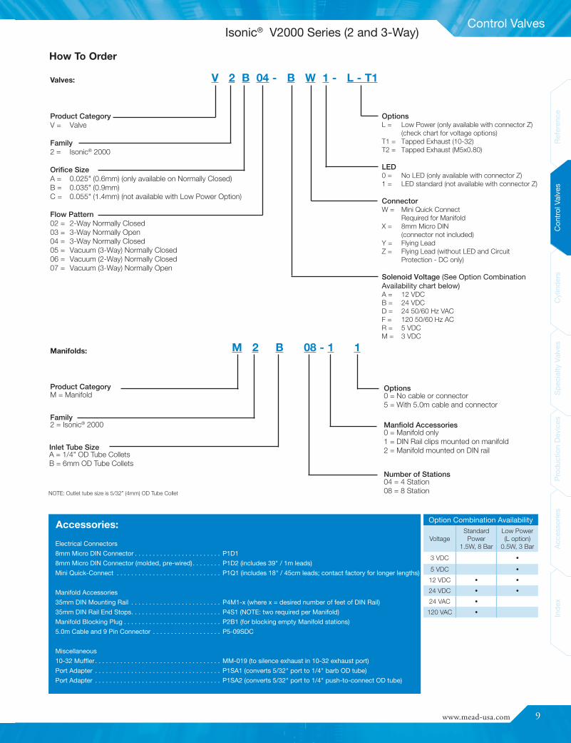
eElectrical Connectors8mm Micro DIN Connector . . . . . . . . . . . . . . . . . . . . . . . . P1D18mm Micro DIN Connector (molded, pre-wired). . . . . . . . P1D2 (includes 39" / 1m leads)Mini Quick-Connect . . . . . . . . . . . . . . . . . . . . . . . . . . . . . P1Q1 (includes 18" / 45cm leads; contact factory for longer lengths)
Manifold Accessories35mm DIN Mounting Rail . . . . . . . . . . . . . . . . . . . . . . . . . P4M1-x (where x = desired number of feet of DIN Rail)35mm DIN Rail End Stops. . . . . . . . . . . . . . . . . . . . . . . . . P4S1 (NOTE: two required per Manifold)Manifold Blocking Plug . . . . . . . . . . . . . . . . . . . . . . . . . . . P2B1 (for blocking empty Manifold stations)5.0m Cable and 9 Pin Connector . . . . . . . . . . . . . . . . . . . P5-09SDC
Miscellaneous10-32 Muffler . . . . . . . . . . . . . . . . . . . . . . . . . . . . . . . . . . . MM-019 (to silence exhaust in 10-32 exhaust port)Port Adapter . . . . . . . . . . . . . . . . . . . . . . . . . . . . . . . . . . . P1SA1 (converts 5/32" port to 1/4" barb OD tube)Port Adapter . . . . . . . . . . . . . . . . . . . . . . . . . . . . . . . . . . . P1SA2 (converts 5/32" port to 1/4" push-to-connect OD tube)
Accessories:
Product CategoryV = Valve
Family2 = Isonic® 2000
Orifice SizeA = 0.025" (0.6mm) (only available on Normally Closed)B = 0.035" (0.9mm)C = 0.055" (1.4mm) (not available with Low Power Option)
Flow Pattern02 = 2-Way Normally Closed03 = 3-Way Normally Open04 = 3-Way Normally Closed05 = Vacuum (3-Way) Normally Closed06 = Vacuum (2-Way) Normally Closed07 = Vacuum (3-Way) Normally Open
V 2 B 04 - B W 1 - L - T1Valves:
Option Combination Availability
VoltageStandard
Power1.5W, 8 Bar
Low Power(L option)
0.5W, 3 Bar
3 VDC •
5 VDC •
12 VDC • •
24 VDC • •
24 VAC •
120 VAC •
OptionsL = Low Power (only available with connector Z)
(check chart for voltage options)T1 = Tapped Exhaust (10-32)T2 = Tapped Exhaust (M5x0.80)
LED0 = No LED (only available with connector Z)1 = LED standard (not available with connector Z)
ConnectorW = Mini Quick Connect
Required for ManifoldX = 8mm Micro DIN
(connector not included)Y = Flying LeadZ = Flying Lead (without LED and Circuit
Protection - DC only)
Solenoid Voltage (See Option CombinationAvailability chart below)A = 12 VDCB = 24 VDCD = 24 50/60 Hz VACF = 120 50/60 Hz ACR = 5 VDCM = 3 VDC
How To Order
M 2 B 08 - 1 1Manifolds:
Product CategoryM = Manifold
Family2 = Isonic® 2000
Inlet Tube SizeA = 1/4" OD Tube ColletsB = 6mm OD Tube Collets
Number of Stations04 = 4 Station08 = 8 Station
Manfiold Accessories0 = Manifold only1 = DIN Rail clips mounted on manifold2 = Manifold mounted on DIN rail
Options0 = No cable or connector5 = With 5.0m cable and connector
NOTE: Outlet tube size is 5/32” (4mm) OD Tube Collet
Isonic® V2000 Series (2 and 3-Way)
10
Control Valves
ReferenceControlValves
CylindersSpecialtyValves
ProductionDevices
AccessoriesIndex
Voltage Amps Resistance InitialPower
Continuous On
12DC 0.133 92 1.6 1.324DC 0.058 406 1.4 1.224AC 0.058 406 1.4 1.2
120AC 0.014 8350 1.7 1.5
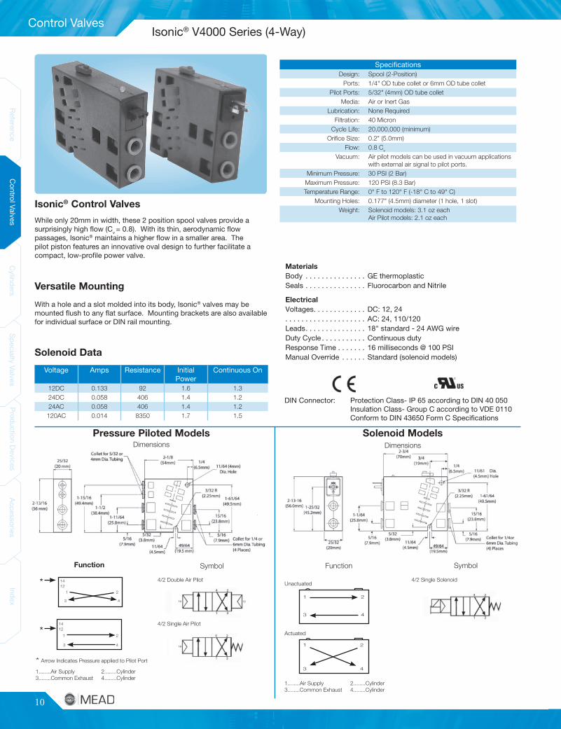
MaterialsBody . . . . . . . . . . . . . . . GE thermoplasticSeals . . . . . . . . . . . . . . . Fluorocarbon and NitrileElectricalVoltages. . . . . . . . . . . . . DC: 12, 24. . . . . . . . . . . . . . . . . . . . AC: 24, 110/120Leads. . . . . . . . . . . . . . . 18" standard - 24 AWG wireDuty Cycle . . . . . . . . . . . Continuous dutyResponse Time . . . . . . . 16 milliseconds @ 100 PSIManual Override . . . . . . Standard (solenoid models)
DIN Connector: Protection Class- IP 65 according to DIN 40 050Insulation Class- Group C according to VDE 0110Conform to DIN 43650 Form C Specifications
Unactuated
1 2
3 4
Actuated
1 2
3 4
1
1412* 4/2 Single Solenoid
1........Air Supply 2........Cylinder3........Common Exhaust 4........Cylinder
* Arrow Indicates Pressure applied to Pilot Port
4/2 Double Air Pilot
4/2 Single Air Pilot
Function Symbol
1........Air Supply 2........Cylinder3........Common Exhaust 4........Cylinder
Function Symbol
Solenoid Models
2
3 4
*1
1412
2
3 4
DimensionsDimensions
SpecificationsDesign: Spool (2-Position)
Ports: 1/4" OD tube collet or 6mm OD tube colletPilot Ports: 5/32" (4mm) OD tube collet
Media: Air or Inert GasLubrication: None Required
Filtration: 40 MicronCycle Life: 20,000,000 (minimum)
Orifice Size: 0.2" (5.0mm)Flow: 0.8 Cv
Vacuum: Air pilot models can be used in vacuum applicationswith external air signal to pilot ports.
Minimum Pressure: 30 PSI (2 Bar)Maximum Pressure: 120 PSI (8.3 Bar)Temperature Range: 0° F to 120° F (-18° C to 49° C)
Mounting Holes: 0.177" (4.5mm) diameter (1 hole, 1 slot)Weight: Solenoid models: 3.1 oz each
Air Pilot models: 2.1 oz each
Isonic® Control Valves
While only 20mm in width, these 2 position spool valves provide asurprisingly high flow (Cv = 0.8). With its thin, aerodynamic flowpassages, Isonic® maintains a higher flow in a smaller area. Thepilot piston features an innovative oval design to further facilitate acompact, low-profile power valve.
Versatile Mounting
With a hole and a slot molded into its body, Isonic® valves may bemounted flush to any flat surface. Mounting brackets are also availablefor individual surface or DIN rail mounting.
Solenoid Data
Pressure Piloted Models
Isonic® V4000 Series (4-Way)

www.mead-usa.com #11
Control Valves
Spec
ialty
Valve
sProd
uctio
nDe
vices
Acce
ssories
Inde
xCy
linde
rsCo
ntrolV
alves
Referenc
eInde
xAc
cess
ories
Prod
uctio
nDe
vices
Spec
ialty
Valve
sCy
linde
rsCo
ntrolV
alves
Referenc
e
V4 Manifold Dimensions
Stations “A” “B” “C”
21-61/64
(49.5 mm)2-35/64
(64.7 mm)4-9/64
(105 mm)
32-25/32
(70.5 mm)3-3/8
(85.6 mm)4-15/16
(125 mm)
43-39/64
(91.5 mm)4-13/64
(106.7 mm)5-49/64
(146 mm)
55-9/64
(130.5 mm)5-57/64
(149.6 mm)7-19/64
(185 mm)
65-31/32
(151.5 mm)6-9/16
(166.7 mm)8-1/8
(206 mm)
76-51/64
(172.5 mm)7-25/64
(187.7 mm)8-61/64
(227 mm)
87-5/8
(193.5 mm)8-7/32
(208.7mm)9-25/32
(248 mm)
The Quick-Change ManifoldThe Isonic® manifold system has been designed to virtuallyeliminate downtime. Connecting any valve to the manifold baseis as easy as plugging in an electrical cord. With this patented“plug-in” design, replacing an individual valve on the manifold canbe accomplished in a matter of seconds!
Isonic® Manifold Expands With Your NeedsAvailable in two, three or four station segments, the manifold’sunique modular design creates a versatile, expandable controlbase. For manifolds larger than four stations, two or moresegments can be easily combined to create any size manifold(multiple segments are assembled on DIN rail and secured with endstops). Manifold segments are easily isolated for applications withdifferential pressures.Mounting Options
The Isonic® manifold can be either foot mounted or DIN railmounted. 35mm DIN rail can be ordered from Mead.
Manifold SpecificationsCommon Air Inlet Both ends: built in collets for
3/8" OD (or 10mm) tubingFoot Mounting 0.177 (4.5 mm) diameterDIN Rail Mounting Attaches to 35 mm DIN rail
Manifold:
Product CategoryM = Manifold
Family4 = Isonic 4000 (4-way)
Collet SizeA = 3/8" O.D Tube Collets (Common Air Inlet)B = 10mm O.D. Tube Collets (Common Air Inlet)
Number of Stations02 = 2 Stations03 = 3 Stations04 = 4 StationsN = N Stations(modular segments are combined for manifolds over 4 stations)
M 4 A 03 - 2 Y
Wiring OptionsN = NoneY = Pre-wired 10-pin ribbon connector*
(wiring cover included)C = Manifold with wiring cover
* Compatible with mini quick connect valvesonly.
Manifold Assembly0 = Manifold Only2 = Manifold Mounted on DIN rail
(required for 5 or more stations)
Valves:
Product CategoryV = Valve
Family4 = Isonic 4000 (4-way)
Collet SizeA = 1/4" O.D. Tube ColletB = 6mm O.D. Tube Collet
Actuator Type0507 = Single Air Pilot, Spring Return0505 = Double Air Pilot0307 = Single Solenoid, Spring Return
V 4 A- 0307 - A W 1 - (**)
OptionsV = Pilot Breather Vent Filter
LED0 = (only available with connector Z)1 = LED (not available with connector Z)
Connector0 = None (pressure models)W = Mini Quick ConnectX = 8mm Micro DIN ConnectorY = Flying LeadZ = Flying Lead (without LED and Circuit
Protection - DC only)
Solenoid Voltage0 = None (pressure models)A = 12 DCB = 24 DCD = 24 50/60 Hz ACF = 110 / 120 50/60 Hz AC
How To Order
Isonic® V4000 Series (4-Way)

12
Control Valves
ReferenceControlValves
Cylinders
SpecialtyValves
Pr oductionDevices
AccessoriesIndex
Simple, Cost Effective Manifold Wiring
Mead's Manifold PowerStrip™ (MPS) offers a simple solution to
wiring manifold valve stacks. The MPS reduces installation time,
simplifies troubleshooting, and provides a clean, space-efficient
alternative to individual wiring and costly molded cable sets.
Features and Benefits
• Simplify Wiring
• Eliminates bundled wire sets with a single home-run cable
• Reliable Design
• IP65 ingress protection
• Ultrasonic-welded construction
• Non-metallic, corrosion resistant
• Cost Effective
• Reduce installation time
• Replaces individually wired DIN connectors and molded
cable sets
Specifications
Compatibility: Isonic® V4000 Series
Voltage Range: 0-120 VAC/VDC
Temperature Range: 0° F to 120° F Ambient (-18° C to 49° C)
Maximum Coil Power: 2W
Electrical Connection: 5-Pin M12 Male
Enclosure Rating: IP65
Body Material: ABS
Valve Compatibility
Valve Series Manifold Manifold PowerStrip™
V4_-0307-_X1-_ M4_ _-_N MPS5-_-_
Model Includes
MPS5-_ Manifold PowerStrip™, Screws, Gaskets
MPS5-_-C10Manifold PowerStrip™, Screws, Gaskets, 10m M12
Cable
Product Contents
How to Order
MPS 5 - 4 - C10
Optional CableBlank - NoneC10 - 10M Mating Cable (MPS5)
Model5 - V4000 SeriesNumber of Stations2 - Two (2) Stations3 - Three (3) Stations4 - Four (4) Stations
Wiring Diagram
Dimensions - in [mm] Accessories
NEW!
Manifold PowerStrip™
www.mead-usa.com #13
Control Valves
Spec
ialty
Valve
sProd
uctio
nDe
vices
Acce
ssories
Inde
xCy
linde
rsCo
ntrolV
alves
Referenc
eInde
xAc
cess
ories
Prod
uctio
nDe
vices
Spec
ialty
Valve
sCy
linde
rsCo
ntrolV
alves
Referenc
e
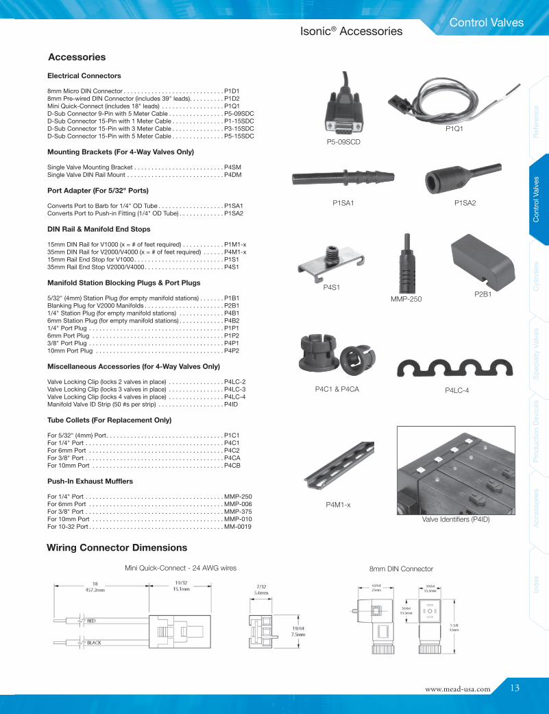
Accessories
P1SA1 P1SA2
P4C1 & P4CA P4LC-4
P1Q1
P4M1-x
P5-09SCD
Valve Identifiers (P4ID)
P2B1P4S1
MMP-250
Electrical Connectors
8mm Micro DIN Connector . . . . . . . . . . . . . . . . . . . . . . . . . . . . . P1D18mm Pre-wired DIN Connector (includes 39" leads). . . . . . . . . . P1D2Mini Quick-Connect (includes 18" leads) . . . . . . . . . . . . . . . . . . P1Q1D-Sub Connector 9-Pin with 5 Meter Cable . . . . . . . . . . . . . . . . P5-09SDCD-Sub Connector 15-Pin with 1 Meter Cable . . . . . . . . . . . . . . . P1-15SDCD-Sub Connector 15-Pin with 3 Meter Cable . . . . . . . . . . . . . . . P3-15SDCD-Sub Connector 15-Pin with 5 Meter Cable . . . . . . . . . . . . . . . P5-15SDC
Mounting Brackets (For 4-Way Valves Only)
Single Valve Mounting Bracket . . . . . . . . . . . . . . . . . . . . . . . . . . P4SMSingle Valve DIN Rail Mount . . . . . . . . . . . . . . . . . . . . . . . . . . . . P4DM
Port Adapter (For 5/32" Ports)
Converts Port to Barb for 1/4" OD Tube . . . . . . . . . . . . . . . . . . . P1SA1Converts Port to Push-in Fitting (1/4" OD Tube) . . . . . . . . . . . . . P1SA2
DIN Rail & Manifold End Stops
15mm DIN Rail for V1000 (x = # of feet required) . . . . . . . . . . . . P1M1-x35mm DIN Rail for V2000/V4000 (x = # of feet required) . . . . . . P4M1-x15mm Rail End Stop for V1000. . . . . . . . . . . . . . . . . . . . . . . . . . P1S135mm Rail End Stop V2000/V4000. . . . . . . . . . . . . . . . . . . . . . . P4S1
Manifold Station Blocking Plugs & Port Plugs
5/32" (4mm) Station Plug (for empty manifold stations) . . . . . . . P1B1Blanking Plug for V2000 Manifolds . . . . . . . . . . . . . . . . . . . . . . . P2B11/4" Station Plug (for empty manifold stations) . . . . . . . . . . . . . P4B16mm Station Plug (for empty manifold stations) . . . . . . . . . . . . . P4B21/4" Port Plug . . . . . . . . . . . . . . . . . . . . . . . . . . . . . . . . . . . . . . . P1P16mm Port Plug . . . . . . . . . . . . . . . . . . . . . . . . . . . . . . . . . . . . . . P1P23/8" Port Plug . . . . . . . . . . . . . . . . . . . . . . . . . . . . . . . . . . . . . . . P4P110mm Port Plug . . . . . . . . . . . . . . . . . . . . . . . . . . . . . . . . . . . . . P4P2
Miscellaneous Accessories (for 4-Way Valves Only)
Valve Locking Clip (locks 2 valves in place) . . . . . . . . . . . . . . . . P4LC-2Valve Locking Clip (locks 3 valves in place) . . . . . . . . . . . . . . . . P4LC-3Valve Locking Clip (locks 4 valves in place) . . . . . . . . . . . . . . . . P4LC-4Manifold Valve ID Strip (50 #s per strip) . . . . . . . . . . . . . . . . . . . P4ID
Tube Collets (For Replacement Only)
For 5/32" (4mm) Port. . . . . . . . . . . . . . . . . . . . . . . . . . . . . . . . . . P1C1For 1/4" Port . . . . . . . . . . . . . . . . . . . . . . . . . . . . . . . . . . . . . . . . P4C1For 6mm Port . . . . . . . . . . . . . . . . . . . . . . . . . . . . . . . . . . . . . . . P4C2For 3/8" Port . . . . . . . . . . . . . . . . . . . . . . . . . . . . . . . . . . . . . . . . P4CAFor 10mm Port . . . . . . . . . . . . . . . . . . . . . . . . . . . . . . . . . . . . . . P4CB
Push-In Exhaust Mufflers
For 1/4" Port . . . . . . . . . . . . . . . . . . . . . . . . . . . . . . . . . . . . . . . . MMP-250For 6mm Port . . . . . . . . . . . . . . . . . . . . . . . . . . . . . . . . . . . . . . . MMP-006For 3/8" Port . . . . . . . . . . . . . . . . . . . . . . . . . . . . . . . . . . . . . . . . MMP-375For 10mm Port . . . . . . . . . . . . . . . . . . . . . . . . . . . . . . . . . . . . . . MMP-010For 10-32 Port . . . . . . . . . . . . . . . . . . . . . . . . . . . . . . . . . . . . . . . MM-0019
Isonic® Accessories
Mini Quick-Connect - 24 AWG wires 8mm DIN Connector
Wiring Connector Dimensions

14
Control Valves
ReferenceControlValves
CylindersSpecialtyValves
ProductionDevices
AccessoriesIndex
N1 Model N2 Model Actuator Return DescriptionMin. PilotPressure
Available Voltages Wiring TypeDC AC
N1-DP N2-DP Air Pilot Air Pilot Double Pressure Piloted 10 PSI - - -N1-SP N2-SP Air Pilot Spring Single Pressure Piloted 40 PSI - - -N1-DB N2-DB Bleed Pilot Bleed Pilot Double Bleed Piloted 40 PSI - - -N1-HL N2-HL Hand Lever Spring Light 3lb. Touch - - - -
N1-PB N2-PB Push Button Push Button Detent 40 PSI - - -N1-F4 N2-F4 Foot Pedal Spring Foot Valve w/ Cover - - - -
N1-SCD* N2-SCD* Solenoid Spring DIN Connector Solenoid 40 PSI 12-24 24-120-220-240 DIN*N1-SX* N2-SX Solenoid Spring Explosion Proof 40 PSI - 120 Conduit
N1-DCD* N2-DCD* Solenoid Solenoid DIN Connector Solenoids 10 PSI 12-24 24-120-220-240 DIN*N1-DX N2-DX Solenoid Solenoid Explosion Proof 10 PSI - 120 Conduit
Operating Parameters N2Media: Air or Inert Gas
Pressure: Vacuum to 120 PSIPort Size: 1/4" NPTF
Pilot Ports: 1/8" NPSFFlow: Cv = 1.0 (single valves)
Cv = 1.2 (stacked valves)Temperature: 0° F to 120° F
(-18° C to 49° C)Lubrication: Petroleum Base Oil
Filtration: 40 Micron MinimumSol Response: 30-40 ms
Seals: Buna-N
Operating Parameters N1Media: Air or Inert Gas
Pressure: Vacuum to 120 PSIPort Size: 1/8" NPTF
Pilot Ports: 1/8" NPSFFlow: Cv = 0.7 (single valves)
Cv = 0.9 (stacked valves)Temperature: 0° F to 120° F
(-18° C to 49° C)Lubrication: Petroleum Base Oil
Filtration: 40 Micron MinimumSol Response: 30-40 ms
Seals: Buna-N
N1-SCD - M - 24VACBase ModelStacking OptionVoltage
N2-SCD - M - 24VACBase ModelStacking OptionVoltage
Ordering Example:
N1 = 1/8" ports
N2 = 1/4" ports
* Connector not included on N2-SCD and N2-DCD. See “DIN Solenoid Connectors” on following page.
Ordering Instructions
External Pilot Option (E)Designed For Long LifeNova 4-way directional control valves offer state-of-the-art air valvedesign at a remarkably low price. Nova utilizes a single bonded rubberspool with finely ground sealing lands that travel only .047"... less than1/16th of an inch! This economy of movement assures long valve lifeyet generates enough flow to power a 4" bore cylinder.
For solenoid actuation below the stated minimum pilot pressure or forvacuum applications, a 10-32 tapped external air supply allows thesolenoid to be operated at different pressures than the power section.
Single Valves: State model number and voltage, if applicable.
Stacked Valves: Add an “M” to the single valve model number andstate voltage if applicable - specify number and type of valves in eachstack. NOTE: Explosion-proof coils may not be stacked next to eachother because of their greater size.
External Pilot Supply: Add an “E” to the model number.
1/4" NPTF ported Nova valves produce a large output flow of 57 cubicfeet per minute at 100 PSI inlet pressure (Cv=1.0). Each output port hasits own exhaust port so that individual exhaust control is possible.
Large Air Flow With Dual Exhausts
All Nova valves are supplied with manual overrides so that valveactuation may be triggered without electricity or air to the pilots.
Manual Override as Standard
N1-SPN2-SP
N1-DPN2-DP
Single and Double Air Piloted Single and Double Solenoid
N1-SCDN2-SCD
N1-DCDN2-DCD
Nova Specifications
Solenoids shown here withPVD1 (sold separately)
Nova
www.mead-usa.com #15
Control Valves
Spec
ialty
Valve
sProd
uctio
nDe
vices
Acce
ssories
Inde
xCy
linde
rsCo
ntrolV
alves
Referenc
eInde
xAc
cess
ories
Prod
uctio
nDe
vices
Spec
ialty
Valve
sCy
linde
rsCo
ntrolV
alves
Referenc
e
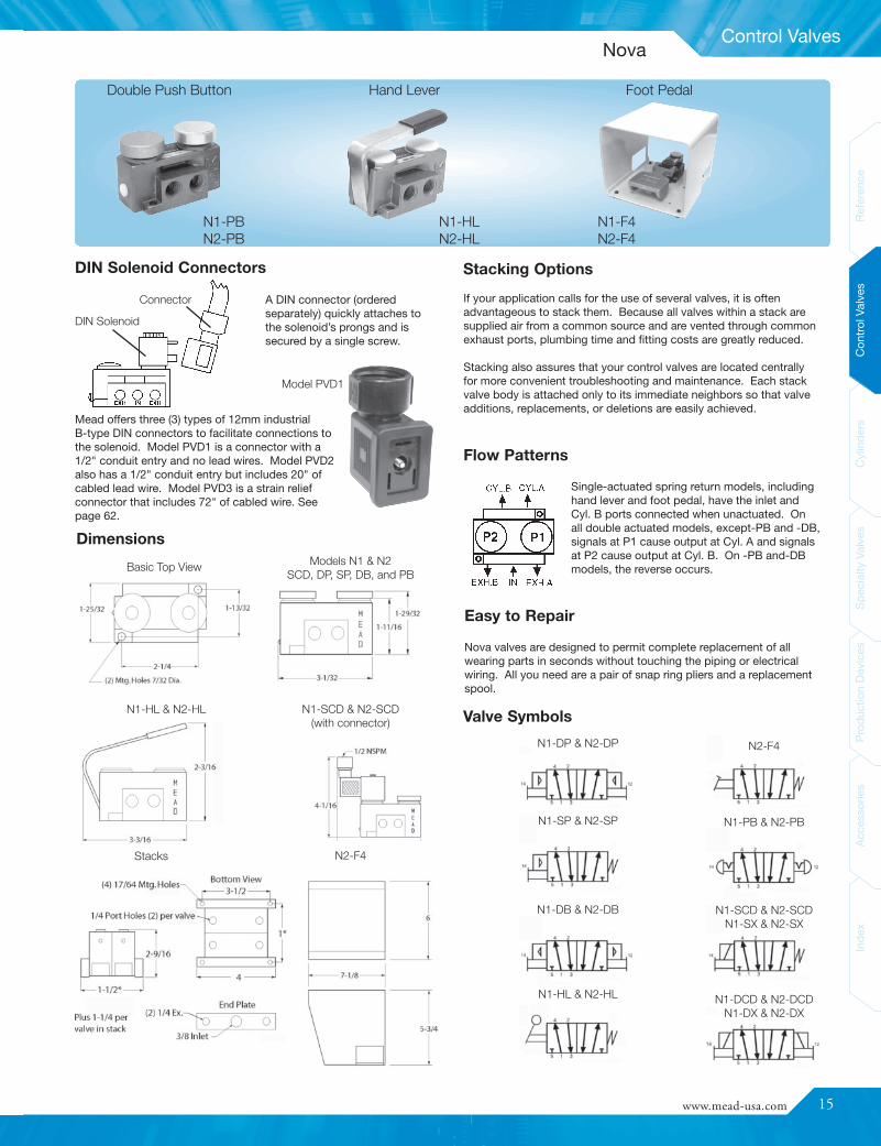
Nova valves are designed to permit complete replacement of allwearing parts in seconds without touching the piping or electricalwiring. All you need are a pair of snap ring pliers and a replacementspool.
Easy to Repair
A DIN connector (orderedseparately) quickly attaches tothe solenoid’s prongs and issecured by a single screw.
Dimensions
Foot Pedal
Stacks
Basic Top View
N2-F4
N1-DP & N2-DP
N1-SP & N2-SP
N1-DB & N2-DB
N1-HL & N2-HL
N2-F4
N1-SCD & N2-SCDN1-SX & N2-SX
N1-DCD & N2-DCDN1-DX & N2-DX
N1-PB & N2-PB
Double Push Button
Models N1 & N2SCD, DP, SP, DB, and PB
Hand Lever
Stacking Options
If your application calls for the use of several valves, it is oftenadvantageous to stack them. Because all valves within a stack aresupplied air from a common source and are vented through commonexhaust ports, plumbing time and fitting costs are greatly reduced.
Stacking also assures that your control valves are located centrallyfor more convenient troubleshooting and maintenance. Each stackvalve body is attached only to its immediate neighbors so that valveadditions, replacements, or deletions are easily achieved.
Single-actuated spring return models, includinghand lever and foot pedal, have the inlet andCyl. B ports connected when unactuated. Onall double actuated models, except-PB and -DB,signals at P1 cause output at Cyl. A and signalsat P2 cause output at Cyl. B. On -PB and-DBmodels, the reverse occurs.
Flow Patterns
Valve SymbolsN1-SCD & N2-SCD(with connector)
N1-HL & N2-HL
N1-PBN2-PB
N1-HLN2-HL
N1-F4N2-F4
DIN Solenoid Connectors
DIN Solenoid
Connector
Model PVD1
Mead offers three (3) types of 12mm industrialB-type DIN connectors to facilitate connections tothe solenoid. Model PVD1 is a connector with a1/2" conduit entry and no lead wires. Model PVD2also has a 1/2" conduit entry but includes 20" ofcabled lead wire. Model PVD3 is a strain reliefconnector that includes 72" of cabled wire. Seepage 62.
Nova
16
Control Valves
ReferenceControlValves
CylindersSpecialtyValves
ProductionDevices
AccessoriesIndex
ModelNumber
PortSize Actuator Return Description
Min. PilotPressure (PSI)
Available VoltagesDC AC
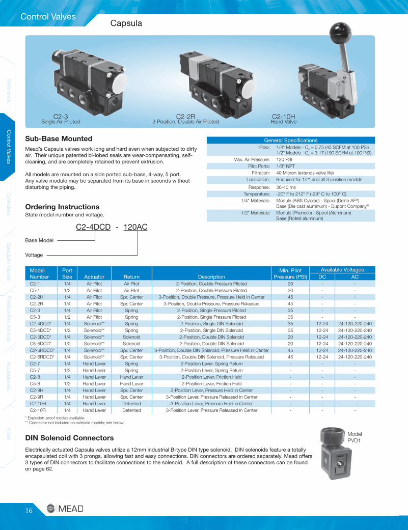
C2-1 1/4 AIr Pilot Air Pilot 2-Position, Double Pressure Piloted 20 - -C5-1 1/2 Air Pilot Air Pilot 2-Position, Double Pressure Piloted 20 - -C2-2H 1/4 Air Pilot Spr. Center 3-Position, Double Pressure, Pressure Held in Center 45 - -C2-2R 1/4 Air Pilot Spr. Center 3-Position, Double Pressure, Pressure Released 45 - -C2-3 1/4 Air Pilot Spring 2-Position, Single Pressure Piloted 35 - -C5-3 1/2 Air Pilot Spring 2-Position, Single Pressure Piloted 35 - -C2-4DCD* 1/4 Solenoid** Spring 2-Position, Single DIN Solenoid 35 12-24 24-120-220-240C5-4DCD* 1/2 Solenoid** Spring 2-Position, SIngle DIN Solenoid 35 12-24 24-120-220-240C2-5DCD* 1/4 Solenoid** Solenoid 2-Position, Double DIN Solenoid 20 12-24 24-120-220-240C5-5DCD* 1/2 Solenoid** Solenoid 2-Position, Double DIN Solenoid 20 12-24 24-120-220-240C2-6HDCD* 1/4 Solenoid** Spr. Center 3-Position, Double DIN Solenoid, Pressure Held in Center 45 12-24 24-120-220-240C2-6RDCD* 1/4 Solenoid** Spr. Center 3-Position, Double DIN Solenoid, Pressure Released 45 12-24 24-120-220-240C2-7 1/4 Hand Lever Spring 2-Position Lever, Spring Return - - -C5-7 1/2 Hand Lever Spring 2-Position Lever, Spring Return - - -C2-8 1/4 Hand Lever Hand Lever 2-Position Lever, Friction Held - - -C5-8 1/2 Hand Lever Hand Lever 2-Position Lever, Friction Held - - -C2-9H 1/4 Hand Lever Spr. Center 3-Position Lever, Pressure Held in Center - - -C2-9R 1/4 Hand Lever Spr. Center 3-Position Lever, Pressure Released in Center - - -C2-10H 1/4 Hand Lever Detented 3-Position Lever, Pressure Held in Center - - -C2-10R 1/4 Hand Lever Detented 3-Position Lever, Pressure Released in Center - - -
General SpecificationsFlow: 1/4" Models - Cv = 0.75 (45 SCFM at 100 PSI)
1/2" Models - Cv = 3.17 (190 SCFM at 100 PSI)Max. Air Pressure: 120 PSI
Pilot Ports: 1/8" NPTFiltration: 40 Micron (extends valve life)
Lubrication: Required for 1/2" and all 3-position models
Response: 30-40 msTemperature: -20° F to 212° F (-29° C to 100° C)
1/4" Materials: Module (ABS Cylolac) - Spool (Delrin AF®)Base (Die cast aluminum) - Dupont Company®
1/2" Materials: Module (Phenolic) - Spool (Aluminum)Base (Rolled aluminum)
C2-4DCD - 120AC
Sub-Base Mounted
Base Model
Voltage
* Explosion-proof models available.** Connector not included on solenoid models; see below.
Ordering InstructionsState model number and voltage.
Single Air PilotedC2-3
3 Position, Double Air PilotedC2-2R
Hand ValveC2-10H
DIN Solenoid ConnectorsModelPVD1
Electrically actuated Capsula valves utilize a 12mm industrial B-type DIN type solenoid. DIN solenoids feature a totallyencapsulated coil with 3 prongs, allowing fast and easy connections. DIN connectors are ordered separately. Mead offers3 types of DIN connectors to facilitate connections to the solenoid. A full description of these connectors can be foundon page 62.
Mead’s Capsula valves work long and hard even when subjected to dirtyair. Their unique patented bi-lobed seals are wear-compensating, self-cleaning, and are completely retained to prevent extrusion.
All models are mounted on a side ported sub-base, 4-way, 5 port.Any valve module may be separated from its base in seconds withoutdisturbing the piping.
Capsula
www.mead-usa.com #17
Control Valves
Spec
ialty
Valve
sProd
uctio
nDe
vices
Acce
ssories
Inde
xCy
linde
rsCo
ntrolV
alves
Referenc
eInde
xAc
cess
ories
Prod
uctio
nDe
vices
Spec
ialty
Valve
sCy
linde
rsCo
ntrolV
alves
Referenc
e
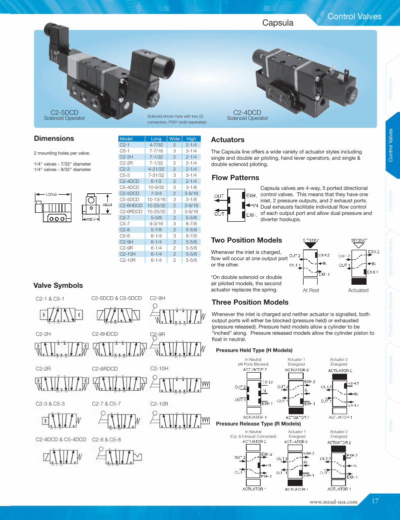
Model Long Wide HighC2-1 4-7/32 2 2-1/4C5-1 7-7/16 3 3-1/4C2-2H 7-1/32 2 2-1/4C2-2R 7-1/32 2 2-1/4C2-3 4-21/32 2 2-1/4C5-3 7-31/32 3 3-1/4C2-4DCD 6-1/2 2 2-1/4C5-4DCD 10-9/32 3 3-1/8C2-5DCD 7-3/4 2 3-9/16C5-5DCD 10-13/16 3 3-1/8C2-6HDCD 10-25/32 2 3-9/16C2-6RDCD 10-25/32 2 3-9/16C2-7 5-3/8 2 5-5/8C5-7 9-3/16 3 8-7/8C2-8 5-7/8 2 5-5/8C5-8 6-1/4 3 8-7/8C2-9H 6-1/4 2 5-5/8C2-9R 6-1/4 2 5-5/8C2-10H 6-1/4 2 5-5/8C2-10R 6-1/4 2 5-5/8
Two Position Models
Whenever the inlet is charged,flow will occur at one output portor the other.
*On double solenoid or doubleair piloted models, the secondactuator replaces the spring. At Rest Actuated
C2-2H
C2-2R
C2-3 & C5-3
C2-4DCD & C5-4DCD
C2-5DCD & C5-5DCD
C2-6HDCD
C2-6RDCD
C2-1 & C5-1
C2-7 & C5-7
C2-8 & C5-8
C2-9H
C2-9R
C2-10H
C2-10R
Dimensions Actuators
The Capsula line offers a wide variety of actuator styles includingsingle and double air piloting, hand lever operators, and single &double solenoid piloting.
Flow PatternsCapsula valves are 4-way, 5 ported directionalcontrol valves. This means that they have oneinlet, 2 pressure outputs, and 2 exhaust ports.Dual exhausts facilitate individual flow controlof each output port and allow dual pressure anddiverter hookups.
Three Position Models
Whenever the inlet is charged and neither actuator is signalled, bothoutput ports will either be blocked (pressure held) or exhausted(pressure released). Pressure held models allow a cylinder to be“inched” along. Pressure released models allow the cylinder piston tofloat in neutral.
Solenoid OperatorC2-5DCD
Solenoid OperatorC2-4DCDSolenoid shown here with two (2)
connectors, PVD1 (sold separately)
2 mounting holes per valve:
1/4" valves - 7/32" diameter1/4" valves - 9/32" diameter
Valve Symbols
Capsula
Pressure Release Type (R Models)In Neutral
(Cyl. & Exhaust Connected)Actuator 1Energized
Actuator 2Energized
Pressure Held Type (H Models)
In Neutral(All Ports Blocked)
Actuator 1Energized
Actuator 2Energized
18
Control Valves
ReferenceControlValves
CylindersSpecialtyValves
ProductionDevices
AccessoriesIndex
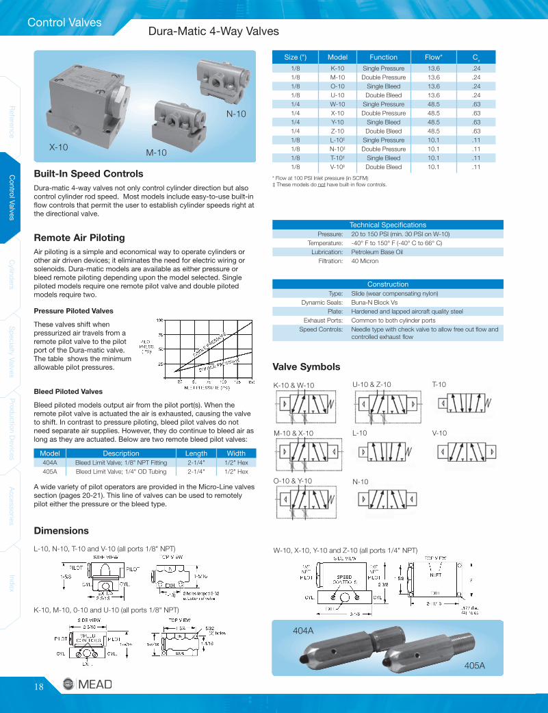
Model Description Length Width404A Bleed Limit Valve; 1/8" NPT Fitting 2-1/4" 1/2" Hex405A Bleed Limit Valve; 1/4" OD Tubing 2-1/4" 1/2" Hex
ConstructionType: Slide (wear compensating nylon)
Dynamic Seals: Buna-N Block VsPlate: Hardened and lapped aircraft quality steel
Exhaust Ports: Common to both cylinder portsSpeed Controls: Needle type with check valve to allow free out flow and
controlled exhaust flow
Technical SpecificationsPressure: 20 to 150 PSI (min. 30 PSI on W-10)
Temperature: -40° F to 150° F (-40° C to 66° C)Lubrication: Petroleum Base Oil
Filtration: 40 Micron
Size (") Model Function Flow* Cv
1/8 K-10 Single Pressure 13.6 .241/8 M-10 Double Pressure 13.6 .241/8 O-10 Single Bleed 13.6 .241/8 U-10 Double Bleed 13.6 .241/4 W-10 Single Pressure 48.5 .631/4 X-10 Double Pressure 48.5 .631/4 Y-10 Single Bleed 48.5 .631/4 Z-10 Double Bleed 48.5 .631/8 L-10‡ Single Pressure 10.1 .111/8 N-10‡ Double Pressure 10.1 .111/8 T-10‡ Single Bleed 10.1 .111/8 V-10‡ Double Bleed 10.1 .11
W-10, X-10, Y-10 and Z-10 (all ports 1/4" NPT)
M-10
N-10
X-10
Valve Symbols
O-10 & Y-10
U-10 & Z-10K-10 & W-10
L-10M-10 & X-10
N-10
T-10
V-10
404A
405A
Built-In Speed Controls
Remote Air PilotingAir piloting is a simple and economical way to operate cylinders orother air driven devices; it eliminates the need for electric wiring orsolenoids. Dura-matic models are available as either pressure orbleed remote piloting depending upon the model selected. Singlepiloted models require one remote pilot valve and double pilotedmodels require two.
Pressure Piloted ValvesThese valves shift whenpressurized air travels from aremote pilot valve to the pilotport of the Dura-matic valve.The table shows the minimumallowable pilot pressures.
Bleed Piloted ValvesBleed piloted models output air from the pilot port(s). When theremote pilot valve is actuated the air is exhausted, causing the valveto shift. In contrast to pressure piloting, bleed pilot valves do notneed separate air supplies. However, they do continue to bleed air aslong as they are actuated. Below are two remote bleed pilot valves:
* Flow at 100 PSI Inlet pressure (in SCFM)‡ These models do not have built-in flow controls.
A wide variety of pilot operators are provided in the Micro-Line valvessection (pages 20-21). This line of valves can be used to remotelypilot either the pressure or the bleed type.
Dura-matic 4-way valves not only control cylinder direction but alsocontrol cylinder rod speed. Most models include easy-to-use built-inflow controls that permit the user to establish cylinder speeds right atthe directional valve.
Dimensions
L-10, N-10, T-10 and V-10 (all ports 1/8" NPT)
K-10, M-10, 0-10 and U-10 (all ports 1/8" NPT)
Dura-Matic 4-Way Valves

www.mead-usa.com #19
Control Valves
Spec
ialty
Valve
sProd
uctio
nDe
vices
Acce
ssories
Inde
xCy
linde
rsCo
ntrolV
alves
Referenc
eInde
xAc
cess
ories
Prod
uctio
nDe
vices
Spec
ialty
Valve
sCy
linde
rsCo
ntrolV
alves
Referenc
e
Model # DescriptionLTV-PB Basic Valve (Unguarded); For Side Mounting
LTV-PBG Valve with Button Guard; For Side MountingLTV-PBGF Valve with Button Guard; For Foot MountingLTV-PBGP Valve with Button Guard; For Panel Mounting
Technical SpecificationsTemperature: 0° F to 115° F (-18° C to 46° C)
Pressure: 25-125 PSI airFiltration: Standard 40 Micron filter recommended to prolong
seal lifeLubrication: Petroleum Based Oil
Flow at 100 PSI: 14 SCFMFlow: 0.24 Cv
Panel Mount(LTV-PBGP)
Foot Mount(LTV-PBGF)
Side Mount(LTV-PB, LTV-PBG)
Dimensions
Panel Mount Addition(Top View)
Foot Mount(Bottom View)
Valve Symbol - All Models
Operating Specifications
Reduce the Effects of Repetitive Motion
How to Order
Mounting Options
Low Stress Two-Hand Control
To provide safer operation of assembly equipment and other machinery,use the LTV Low Stress valves with the CSV-107 two-hand controlunit. When used as directed, this unit demands concurrent actuationfrom two remote inputs before a signal can be initiated. Further, therelease of one or both inputs immediately stops the output signal. Theunit cannot recycle until both valves are again simultaneously actuated.The CSV-107 requires no electrical connections. For more informationregarding the CSV-107, please see page 57.
Many machine operators are required to operate air poweredequipment hundreds or thousands of times per day. These types ofroutines can result in repetitive motion disorders such as Carpal TunnelSyndrome. The debilitating effects usually result in increasing workercompensation claims and declining employee productivity.
Ergonomically designed to respond to extremely low actuation forces,Mead’s Low Stress actuators require as little as 6 ounces of force toinitiate a signal. This valve will dramatically reduce the demands onyour workers’ hands, wrists and arms.
LTV Low Stress valves are ported 1/8" NPT. They are shipped with a3-way normally closed flow pattern for pilot applications, but can beeasily converted to 3-way normally open or 4-way flow by removinga port plug.
Three actuator stickers (red, green and black) are included with eachvalve. All models may be configured 3-way normally open, 3-waynormally closed or 4-way.
The Low Stress Series allows you to choose between three distinctmounting options. Mounting holes are located in the valve body forstandard side mounting. For foot bracket or panel mounting, be sureto specify the proper model number (listed below).
Ergonomic Low Stress Air Valve
20
Control Valves
ReferenceControlValves
CylindersSpecialtyValves
ProductionDevices
AccessoriesIndex
General SpecificationsPressure Range: 25 to 125 PSI
(Solenoid models to 100 PSI)Temperature: 0° F to 115° F (-18° C to 46° C)
Flow: 0.24 Cv
Flow at 100 PSI: 14 SCFMPorts: 1/8" NPT Standard; LTV-60 and LTV-110
pilot ports are 10-32Lubrication: Petroleum Base Oil
Filtration: 40 Micron MinimumBody: Cast AluminumSeals: Buna-NSpool: Aluminum
Response: 20-30 ms
Micrometer Trip Position Adjustment Availableon LTV-10, LTV-15 and LTV-20
Actuated Not Actuated
* For 15/32"panel openings;15/32-32 UNS
Solenoidshown withconnectorPVD1 (soldseparately)
20 & 80 60 & 60L5, 10, 45, 50 & 85 11015, 25, 30, 40 & 75
115DD 120DD 125, 140, MH, EH, FH & ES 130
35 & TP
1/4 to 3/8
Plunger
Adjustment
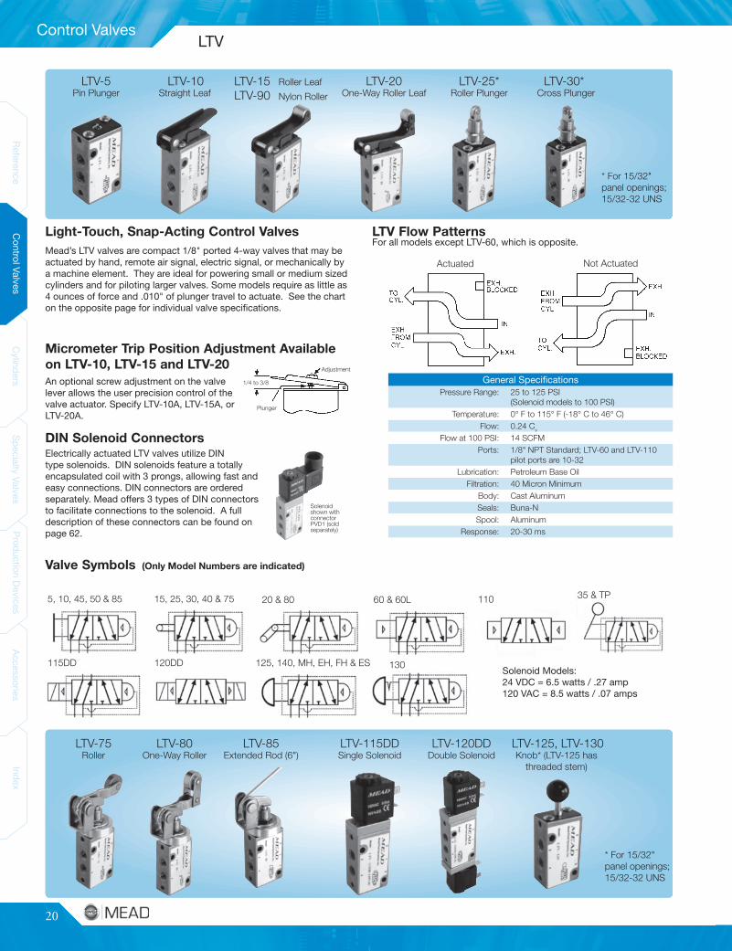
Light-Touch, Snap-Acting Control Valves
DIN Solenoid Connectors
Solenoid Models:24 VDC = 6.5 watts / .27 amp120 VAC = 8.5 watts / .07 amps
Pin PlungerLTV-5
Straight LeafLTV-10 Roller LeafLTV-15
LTV-90 Nylon Roller One-Way Roller LeafLTV-20
Roller PlungerLTV-25*
Cross PlungerLTV-30*
RollerLTV-75
One-Way RollerLTV-80
Extended Rod (6")LTV-85
Single SolenoidLTV-115DD
Double SolenoidLTV-120DD
Knob* (LTV-125 hasthreaded stem)
LTV-125, LTV-130
* For 15/32"panel openings;15/32-32 UNS
LTV Flow PatternsFor all models except LTV-60, which is opposite.
Mead’s LTV valves are compact 1/8" ported 4-way valves that may beactuated by hand, remote air signal, electric signal, or mechanically bya machine element. They are ideal for powering small or medium sizedcylinders and for piloting larger valves. Some models require as little as4 ounces of force and .010" of plunger travel to actuate. See the charton the opposite page for individual valve specifications.
An optional screw adjustment on the valvelever allows the user precision control of thevalve actuator. Specify LTV-10A, LTV-15A, orLTV-20A.
Electrically actuated LTV valves utilize DINtype solenoids. DIN solenoids feature a totallyencapsulated coil with 3 prongs, allowing fast andeasy connections. DIN connectors are orderedseparately. Mead offers 3 types of DIN connectorsto facilitate connections to the solenoid. A fulldescription of these connectors can be found onpage 62.
(Only Model Numbers are indicated)Valve Symbols
LTV
www.mead-usa.com #21
Control Valves
Spec
ialty
Valve
sProd
uctio
nDe
vices
Acce
ssories
Inde
xCy
linde
rsCo
ntrolV
alves
Referenc
eInde
xAc
cess
ories
Prod
uctio
nDe
vices
Spec
ialty
Valve
sCy
linde
rsCo
ntrolV
alves
Referenc
e
Model Actuator Return
Act.Force @80 PSI
Act. Stroke Distance(")
Length(")
Width(")
Height(")Full Open
OverTravel
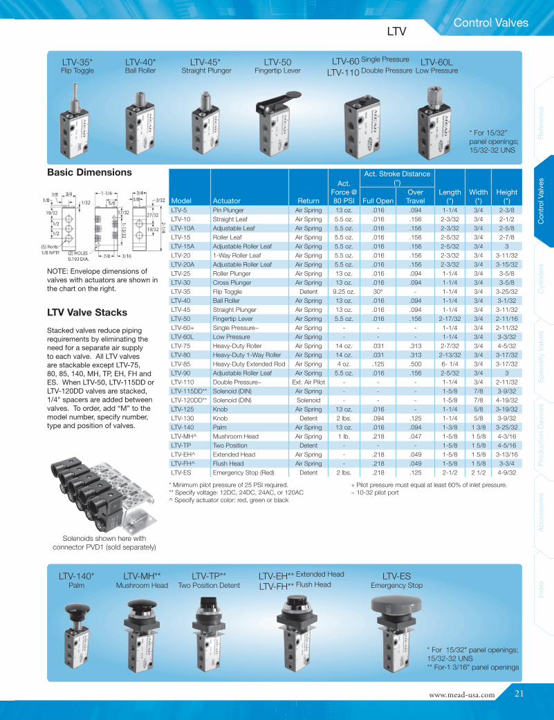
LTV-5 Pin Plunger Air Spring 13 oz. .016 .094 1-1/4 3/4 2-3/8LTV-10 Straight Leaf Air Spring 5.5 oz. .016 .156 2-3/32 3/4 2-1/2LTV-10A Adjustable Leaf Air Spring 5.5 oz. .016 .156 2-3/32 3/4 2-5/8LTV-15 Roller Leaf Air Spring 5.5 oz. .016 .156 2-5/32 3/4 2-7/8LTV-15A Adjustable Roller Leaf Air Spring 5.5 oz. .016 .156 2-5/32 3/4 3LTV-20 1-Way Roller Leaf Air Spring 5.5 oz. .016 .156 2-3/32 3/4 3-11/32LTV-20A Adjustable Roller Leaf Air Spring 5.5 oz. .016 .156 2-3/32 3/4 3-15/32LTV-25 Roller Plunger Air Spring 13 oz. .016 .094 1-1/4 3/4 3-5/8LTV-30 Cross Plunger Air Spring 13 oz. .016 .094 1-1/4 3/4 3-5/8LTV-35 Flip Toggle Detent 9.25 oz. 30° - 1-1/4 3/4 3-25/32LTV-40 Ball Roller Air Spring 13 oz. .016 .094 1-1/4 3/4 3-1/32LTV-45 Straight Plunger Air Spring 13 oz. .016 .094 1-1/4 3/4 3-11/32LTV-50 Fingertip Lever Air Spring 5.5 oz. .016 .156 2-17/32 3/4 2-11/16LTV-60+ Single Pressure~ Air Spring - - - 1-1/4 3/4 2-11/32LTV-60L Low Pressure Air Spring - - - 1-1/4 3/4 3-3/32LTV-75 Heavy-Duty Roller Air Spring 14 oz. .031 .313 2-7/32 3/4 4-5/32LTV-80 Heavy-Duty 1-Way Roller Air Spring 14 oz. .031 .313 2-13/32 3/4 3-17/32LTV-85 Heavy-Duty Extended Rod Air Spring 4 oz. .125 .500 6- 1/4 3/4 3-17/32LTV-90 Adjustable Roller Leaf Air Spring 5.5 oz. .016 .156 2-5/32 3/4 3LTV-110 Double Pressure~ Ext. Air Pilot - - - 1-1/4 3/4 2-11/32LTV-115DD** Solenoid (DIN) Air Spring - - - 1-5/8 7/8 3-9/32LTV-120DD** Solenoid (DIN) Solenoid - - - 1-5/8 7/8 4-19/32LTV-125 Knob Air Spring 13 oz. .016 - 1-1/4 5/8 3-19/32LTV-130 Knob Detent 2 lbs. .094 .125 1-1/4 5/8 3-9/32LTV-140 Palm Air Spring 13 oz. .016 .094 1-3/8 1 3/8 3-25/32LTV-MH^ Mushroom Head Air Spring 1 lb. .218 .047 1-5/8 1 5/8 4-3/16LTV-TP Two Position Detent - - - 1-5/8 1 5/8 4-5/16LTV-EH^ Extended Head Air Spring - .218 .049 1-5/8 1 5/8 3-13/16LTV-FH^ Flush Head Air Spring - .218 .049 1-5/8 1 5/8 3-3/4LTV-ES Emergency Stop (Red) Detent 2 lbs. .218 .125 2-1/2 2 1/2 4-9/32
* For 15/32" panel openings;15/32-32 UNS** For-1 3/16" panel openings
* For 15/32”panel openings;15/32-32 UNS
Solenoids shown here withconnector PVD1 (sold separately)
LTV Valve Stacks
* Minimum pilot pressure of 25 PSI required.** Specify voltage: 12DC, 24DC, 24AC, or 120AC^ Specify actuator color: red, green or black
+ Pilot pressure must equal at least 60% of inlet pressure.~ 10-32 pilot port
NOTE: Envelope dimensions ofvalves with actuators are shown inthe chart on the right.
Stacked valves reduce pipingrequirements by eliminating theneed for a separate air supplyto each valve. All LTV valvesare stackable except LTV-75,80, 85, 140, MH, TP, EH, FH andES. When LTV-50, LTV-115DD orLTV-120DD valves are stacked,1/4" spacers are added betweenvalves. To order, add “M” to themodel number, specify number,type and position of valves.
Flip ToggleLTV-35*
Ball RollerLTV-40*
Straight PlungerLTV-45*
Fingertip LeverLTV-50
Double PressureLTV-110Single PressureLTV-60
Low PressureLTV-60L
PalmLTV-140*
Mushroom HeadLTV-MH**
Two Position DetentLTV-TP**
Emergency StopLTV-ES
Flush HeadLTV-FH**Extended HeadLTV-EH**
Basic Dimensions
LTV

22
Control Valves
ReferenceControlValves
CylindersSpecialtyValves
ProductionDevices
AccessoriesIndex
This hookup provides that flow will occurat C only when air signals are received atA and B. The MV-60 is a 3-way air pilotedvalve.
General SpecificationsPressure Range: Vacuum to 120 PSI
Media: Air or Inert GasFlow: 0.11 Cv
Flow at 100 PSI: 6 SCFMPorts: 1/8" NPT
Cycle Life: 7-10 millionForce to Actuate: As Low as 6.4 Ounces
Max. Ambient Temperature: 115° F (46° C)Lubrication: Not Required
Filtration: 40 MicronSeals: VitonSpool: Dupont Teflon®
Body: Cast Zinc
* For 15/32" panel openings; 15/32-32 UNS
NORMALLY CLOSED NORMALLY OPEN DIVERTER
Pressurized air flowsfrom 3 to 2 whenbutton is not pushed.
Exhaust air flows from2 to 1 when button ispressed.
MV-20 & 80
MV-35 & TP
MV-60
MV-140, EH, FH, MH & ES
MV-15, 25, 30, 40, 75 & 90
MV-5, 10, 45, 50, 70 & 85
2060280 & 2060400
MV-45-C4
Perform “AND” Logic Function with MV-60
Nylon RollerMV-90MV-30*MV-25*MV-20MV-15MV-10MV-5
MV-75 MV-80 (Lever 6" long)MV-85 MV-140* MV-MH‡
Mead’s MV air switches are 3-way 1/8" ported air pilot valves that areidentical in size, actuating style, and mounting characteristics to mostindustrial type electric limit switches. Use them in place of electriclimits to save on hookup cost and eliminate spark hazard. MV valvessimplify circuits by eliminating the need for wire shielding, transformers,and solenoids.
Valve Symbols
MV valves are available with 1/4" brass push to connect fittings.The valve will be provided with a fitting for the inlet, outlet and theexhausts ports. Any MV valve may utilize this option. The valve’s bodyheight increases by 5/16" and the mounting holes are 0.532" apart.
Add Push to Connect 1/4" Fittings
Pressurized air flowsfrom 1 to 2 whenbutton is pushed.
Exhaust air flows from2 to 3 when button isreleased.
Pressurized air flowsfrom 2 to 1 whenbutton is pushed.
Pressurized air flowsfrom 2 to 3 whenbutton is released.This hookup does notprovide for exhaust.
The MV air switch may be piped normally closed, normally open, or asa diverter. These alternatives are described in detail below.
MV 3-Way Switches
* For 15/32” panel openings; 15/32-32 UNS

www.mead-usa.com #23
Control Valves
Spec
ialty
Valve
sProd
uctio
nDe
vices
Acce
ssories
Inde
xCy
linde
rsCo
ntrolV
alves
Referenc
eInde
xAc
cess
ories
Prod
uctio
nDe
vices
Spec
ialty
Valve
sCy
linde
rsCo
ntrolV
alves
Referenc
e
Model Actuator
Act.Forcelbs. @
100 PSI Act. Stroke Distance Envelope Dimensions
NC NO
ToCrackOpen
ToFull
OpenOverTravel Len. Wid. Hgt.
MV-5 Pin Plunger 2.5 3.3 .035 .046 .035 1-3/4 11/16 1MV-10 Straight Leaf 1.2 1.5 .100 .137 .079 2-3/16 11/16 1-1/4MV-15 Steel Roller 1.0 1.3 .100 .137 .079 2-3/16 11/16 1-5/8MV-20 1-Way Roller Leaf 1.0 1.3 .100 .137 .079 2-3/16 11/16 2-1/16MV-25 Roller Plunger 2.8 3.5 .035 .046 .155 1-3/4 11/16 2-3/16MV-30 Cross Roller 2.8 3.5 .035 .046 .155 1-3/4 11/16 2-5/16MV-35 Flip Toggle 1.5 2.3 35° 35° 35° 1-3/4 11/16 2-5/16MV-40 Ball Roller 2.5 3.3 .035 .046 .035 1-3/4 11/16 1-19/32MV-45 Straight Plunger 2.5 3.3 .035 .046 .155 1-3/4 11/16 1-29/32MV-50 Fingertip Lever 1.0 1.3 .100 .137 .079 2-5/8 11/16 1-3/8MV-60 Pressure Piloted 40* 40* - - - 1-3/4 11/16 1-5/8MV-70 Extended Leaf 0.7 1.0 .255 .315 .195 4-1/2 11/16 1-9/16MV-75 HD Roller Leaf 2.8 3.5 .093 .119 .129 2-1/4 1-3/4 3-7/16MV-80 HD 1-Way Roller 2.8 3.5 .093 .119 .129 2-1/8 1-3/4 4-1/8MV-85 HD Extended Rod 0.4 0.6 .637 .782 .330 6-1/4 1-3/4 3-1/8MV-90 Nylon Roller 1.0 1.3 .100 .137 .079 2-3/16 11/16 1-5/8MV-140 Palm Actuator 2.5 3.3 - - - 1-3/4 1-3/8 2-1/4MV-MH Mushroom Head - - - - - 1-3/4 1-1/2 2-5/8MV-TP Two Position - - - - - 1-3/4 1-1/2 3-1/32MV-FH Flush Head - - - - - 1-3/4 1-1/2 2-7/32MV-EH Extended Head - - - - - 1-3/4 1-1/2 2-13/32MV-ES Emergency Stop - - - - - 2-1/2 2-1/2 2-7/8MV-EMS Emergency Stop - - - - - 1-3/4 1-5/8 3-1/4
‡ For 1-3/16" panel opening
Model #2060400G (Guarded)
Basic Valve Dimensions
* PSINO = Normally OpenNC = Normally Closed
NOTE: 2060400 and 2060400G are provided with push to connect fittings as the C4 option(described on opposite page).
MV-TP‡Specify Red, Green or BlackMV-FH (Button Flush)‡
Specify Red, Green or BlackMV-EH (Button 5/16" Up)‡
Red & Spring Return OnlyMV-ES‡
Red & Manual OnlyMV-EMS
Locks In Down PositionMV-35* MV-40* MV-45* MV-50
1/8" NPT Pilot PortMV-60
Lever 4 1/4" longMV-70
Model #2060400Model has plug-in fittings for 1/4" OD tube
Envelope dimensions of valves are shown in the chart to the right.
MV 3-Way Switches
* For 15/32" panel openings; 15/32-32 UNS

24
Control Valves
ReferenceControlValves
CylindersSpecialtyValves
ProductionDevices
AccessoriesIndex
ModelNumber
Actuator StylePort
(NPT)Flow(Cv)
Pre-Travel
OverTravel
ForceReq. @100 PSI
FC-1 Cam Button 3-Way NC 1/8" 0.13 3/64" None 17lbs.FC-2A Cam Button 3-Way NO 1/8" 0.32 1/8" 1/8" 11lbs.FC-101 Cam Button 3-Way NC 3/8" 1.15 1/16" None 30lbsFT-1 Fingertip Lever 3-Way NC 1/8" 0.13 1/4" None 4lbs.FT-2A Fingertip Lever 3-Way NO 1/8" 0.32 7/8" 1/8" 2lbs.FT-4 Fingertip Lever 4-Way 1/8" 0.16 7/8" None 3lbs.FT-101 Fingertip Lever 3-Way NC 3/8" 1.15 3/16" None 8lbs.201 Foot Treadle 3-Way 3/8" 1.15 5/8" None 7-1/2 lbs.
General SpecificationsMedia: Air to 150 PSI
Temperature Range: -40° F to 250° F (-40° C to 121° C)Cam Buttons: Hardened Steel
Spring: Stainless SteelSeals: Buna-NBody: Machined Aluminum
Body (4B-1, 4W-1, 201 and 3C-1): Die Cast Zinc
Dimensions
Models FC-1, & FC-2A, FT-1, FT-2A Models FC-101 & FT-101 Model FT-4
FC-1 FT-1
201
Poppet Spool TypeA high degree of reliability is achieved by these valves with the simpleyet efficient poppet type design. A short operating stroke assuresinstantaneous response while minimizing operator fatigue.
FC-1, FC-2A & FC-101
Valve Symbols
FT-1 & FT-101 FC-2A
Model 201
FT-4 201 (NC Setup) 201 (NO Setup)
Flow PatternsModel 201
FT-4
Supply
NC/Out
NO/Out
201 (Detent Setup)
These compact air valves provide economical cam, fingertip, palm,hand, and foot actuation. 3-way models are ideal for actuating single-acting cylinders and 4-way directional valves. 4-way models aresuitable for the control of double-acting cylinders. Three types of spooldesigns are available.
Model 201 may be adjusted in seconds during installation to bedetented or spring return. The valve may be set up as either normallyopen or normally closed for spring return operation.
General Purpose Cam, Foot, Hand and Button Valves

www.mead-usa.com #25
Control Valves
Spec
ialty
Valve
sProd
uctio
nDe
vices
Acce
ssories
Inde
xCy
linde
rsCo
ntrolV
alves
Referenc
eInde
xAc
cess
ories
Prod
uctio
nDe
vices
Spec
ialty
Valve
sCy
linde
rsCo
ntrolV
alves
Referenc
e
ModelNumber
Actuator StylePort
(NPT)Flow(Cv)
Pre-Travel
OverTravel
ForceReq. @100 PSI
3C-1 Cam Button 3-Way NC 1/4" 0.48 1/16" None 9lbs.4B-1 Hand 4-Way 1/4" 0.48 5/8" None 5lbs.4W-1 Foot Treadle 4-Way 1/4" 0.48 5/16" None 18lbs.
ModelNumber
Actuator StylePort
(NPT)Flow(Cv)
Pre-Travel
OverTravel
ForceReq. @100 PSI
FC-51 Cam Button 3-Way NC 1/8" 0.81 1/8" 1/8" 7lbs.FC-52 Cam Button 3-Way NO 1/8" 0.68 1/8" 1/8" 5lbs.PC-51 Palm Button Spr. Ret. 3-Way NC 1/8" 0.81 1/8" 1/8" 7lbs.
PC-51A Palm Button Detent 3-Way NC 1/8" 0.81 1/8" 1/8" 3lbs.PC-52 Palm Button 3-Way NO 1/8" 0.68 1/8" 1/8" 5lbs.
3C-1
4B-14W-1
FC-51
PC-51
FC-52 PC-51 & PC-51A PC-52
3C-1
4B-14W-1
Dimensions
FC-52
Spool Type - Rugged Conditions
Valve Symbols Dimensions
NOTE: height is 1-1/2".
NOTE: width is 3-5/16".
Actuating Force remains constant regardless of air pressure due tothe balanced spool design. This series is particularly suited for use insituations where a high rate of flow is required through a 3-Way camor palm button valve. Additionally, the spool design eliminates themomentary loss of pressure due to valve shifting.
Balanced Spool Type
Time-tested reliability is the trademark of these valves. Due to theunique design, performance is not greatly affected by the use ofunclean air and operation in chip and dirt-ridden environments.
Flow Patterns
Models 4B-1 and 4W-1
NOTE: In neutral, cylinder ports are dumped to atmosphere.
Valve Symbols
General Purpose Cam, Foot, Hand and Button Valves

26
Cylinders
ReferenceControlValves
CylindersSpecialtyValves
ProductionDevices
AccessoriesIndex
ReferenceControlValves
CylindersSpecialtyValves
ProductionDevices
AccessoriesIndex
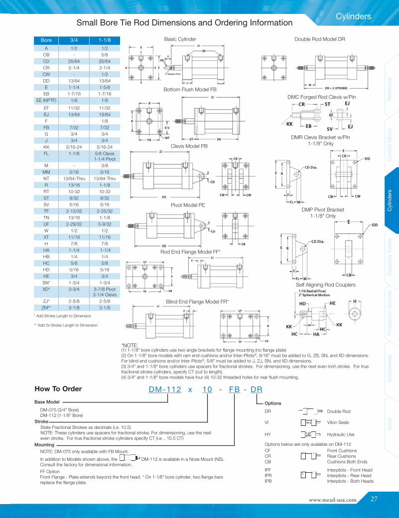
BoreDiam.
Thrust*ThrustMult.**
Rod Diam.(In.)
Max. Oper.Air Oil‡
3/4" 44 .44 5/16 250 10001-1/8" 100 1.00 5/16 250 1000
Part # Rod Thread Cylinder TypeDMA-312 5/16-24 C-112, DM-075, DM-112DMA-375 3/8-24 No StandardDMA-437 7/16-20 DM-150, DM2-150, HD1-150, DM-200, DM2-
200, HD1-200, DM-250, DM2-250, HD1-250
DMA-500 1/2-20 C-150DMA-625 5/18-18 C-250DMA-750 3/4-16 DM-325, DM2-325, HD1-325, DM-400, DM2-
400, HD1-400
DMA-875 7/8-14 No StandardDMA-1000 1-14 C-300, DM-600, HD1-600DMA-1250 1-1/4-12 No Standard
AccessoriesBore Diameter 3/4" 1-1/8"
Flex Rod Couplers DMA-312 DMA-312
Forged Rod Clevis DMC-5 DMC-5
Pivot Bracket NA DMP-7
Clevis Bracket(with pin)
NA DMR-7
Operating SpecificationsTemp. Range: -40° F to 250° F (-40° C to 121° C) (to 400° F [204° C]
on request)Lubrication: Not necessary, but will extend cylinder life when operated
with dry air.Filtration: Not essential, but a standard 40 micron filter placed
upstream will prolong seal life.
Heads: Machined from solid aluminum; black anodizedTubes: Aluminum hard anodized to 60 Rc (16 RMS
finish)Piston: Solid high alloy aluminum
Rod: Hard chrome plated ground and polished steelBearing: Long wearing, oil impregnated porous bronze
Piston and Rod Seals: Wear compensating Buna-N vee ringsRod Wiper: PTFE
Tie Rods: High tensile steel torqued to allow for flexure
Operating Parameters
Pneumatic End-of-Stroke Sensors (Inter-Pilots®)
Pneumatic Stroke Completion Sensors (SCS)
Double-Rod Cylinders
Specify Cushions for Shock Absorption
Self Aligning Rod Couplers
* Pushing force of cylinder at 100 PSI inlet pressure. Pulling force will be about 10% less due tothe displacement of the piston rod. NOTE: Actual realizable thrust could be somewhat lower dueto side loading and internal friction. It is best to oversize your cylinder by about 25% to assuresmooth operation.
** To determine thrust at other inlet pressures, multiply factor by the desired pressure.‡DM cylinders are not rated or approved for use in hydraulic circuits where an impulse or pressurespike may occur.
Cylinder Materials
Cylinders having a common piston rod that protrudes from both endsare available in all bore sizes. In addition to providing a dual powersource, double rod cylinders serve to minimize rod deflection and tofacilitate the control and adjustment of rod travel.
Model DM-112 is available with adjustable cushions that decelerate thepiston rod over the last 11/16" of stroke. They allow the user to set thedegree of cushioning needed for each specific application.
NOTE: Cushions are not recommended for hydraulic use.
A miniature 3-way valve built into the cylinderhead is actuated by the cylinder piston as itreaches the end of its stroke. Once contacted,the 3-way Inter-Pilot® valve emits an air signal.In this manner, sequencing is achieved withoutexternal limit switches and electric wiring.
Inter-Pilots® may be built(10-32 Ports) into either or
both cylinder heads. They are not for hydraulicuse. Cylinder operating pressure must not exceedpressure used to feed the Inter-Pilot®. Inter-Pilots®
are not available on DM-075.
Rod couplers simplify cylinder alignment problems by compensatingfor 2ϒ angular error and 1/16" lateralmisalignment on both extension andretraction strokes. Greater reliabilityis achieved by reducing cylinder andcomponent wear. Order model #DMA-312for these small bore cylinders. For othermodels, see page 41 for dimensions.
Port mounted SCS valves emit an air signalwhen the cylinder rod has stopped even if thepiston has not contacted the end cap. SCSvalves are ideal for use in situations where thefull cylinder stroke is not used. See page 54.
Small Bore Tie Rod
www.mead-usa.com #27
Inde
xAc
cess
ories
Prod
uctio
nDe
vices
Spec
ialty
Valve
sCy
linde
rsCo
ntrolV
alves
Referenc
e
Cylinders
Options
DR Double Rod
VI Viton Seals
HY Hydraulic Use
Options below are only available on DM-112CF Front CushionsCR Rear CushionsCB Cushions Both Ends
IPF Interpilots - Front HeadIPR Interpilots - Rear HeadIPB Interpilots - Both Heads
How To Order DM-112 x 10 - FB - DR
5/8 Clevis1 1/4 Pivot
DMR Clevis Bracket w/Pin1-1/8" Only
DMC Forged Rod Clevis w/Pin
Self Aligning Rod Couplers
DMP Pivot Bracket1-1/8" Only
Basic Cylinder
Bottom Flush Model FB
Clevis Model PB
Rod End Flange Model FF*
Double Rod Model DR
Pivot Model PE
Blind End Flange Model FR*
* Add Stroke Length to Dimension
** Add 2x Stroke Length to Dimension
Bore 3/4 1-1/8
A 1/2 1/2CB - 5/8CD 25/64 25/64CR 2-1/4 2-1/4CW - 1/2DD 13/64 13/64E 1-1/4 1-5/8
EB 1-7/16 1-7/16EE (NPTF) 1/8 1/8
EF 11/32 11/32EJ 13/64 13/64F - 1/8
FB 7/32 7/32G 3/4 3/4J 3/4 3/4
KK 5/16-24 5/16-24FL 1-1/8 5/8 Clevis
1-1/4 PivotM - 3/8
MM 5/16 5/16NT 13/64-Thru 13/64-ThruR 13/16 1-1/8
RT 10-32 10-32ST 9/32 9/32SV 5/16 5/16TF 2-13/32 2-25/32TN 13/16 1-1/8UF 2-29/32 3-9/32W 1/2 1/2XT 11/16 11/16H 7/8 7/8
HA 1-1/4 1-1/4HB 1/4 1/4HC 5/8 5/8HD 5/16 5/16HE 3/4 3/4SN* 1-3/4 1-3/4XD* 3-3/4 3-7/8 Pivot
3-1/4 ClevisZJ* 2-5/8 2-5/8
ZM** 3-1/8 3-1/8
State Fractional Strokes as decimals (i.e. 10.5)NOTE: These cylinders use spacers for fractional stroke. For dimensioning, use the nexteven stroke. For true fractional stroke cylinders specify CT (i.e. , 10.5 CT)
Stroke
DM-075 (3/4" Bore)DM-112 (1-1/8" Bore)
Base Model
Mounting
NOTE: DM-075 only available with FB Mount.In addition to Models shown above, the DM-112 is available in a Nose Mount (NS).Consult the factory for dimensional information.FF OptionFront Flange - Plate extends beyond the front head. * On 1-1⁄8" bore cylinder, two flange barsreplace the flange plate.
(1) 1-1/8" bore cylinders use two angle brackets for flange mounting (no flange plate)(2) On 1-1/8" bore models with ram end cushions and/or Inter-Pilots®, 9/16" must be added to G, ZB, SN, and XD dimensions.For blind end cushions and/or Inter-Pilots®, 5/8" must be added to J, ZJ, SN, and XD dimensions.(3) 3/4" and 1-1/8" bore cylinders use spacers for fractional strokes. For dimensioning, use the next even inch stroke. For truefractional stroke cylinders, specify CT (cut to length).(4) 3/4" and 1-1/8" bore models have four (4) 10-32 threaded holes for rear flush mounting.
*NOTE:
Small Bore Tie Rod Dimensions and Ordering Information
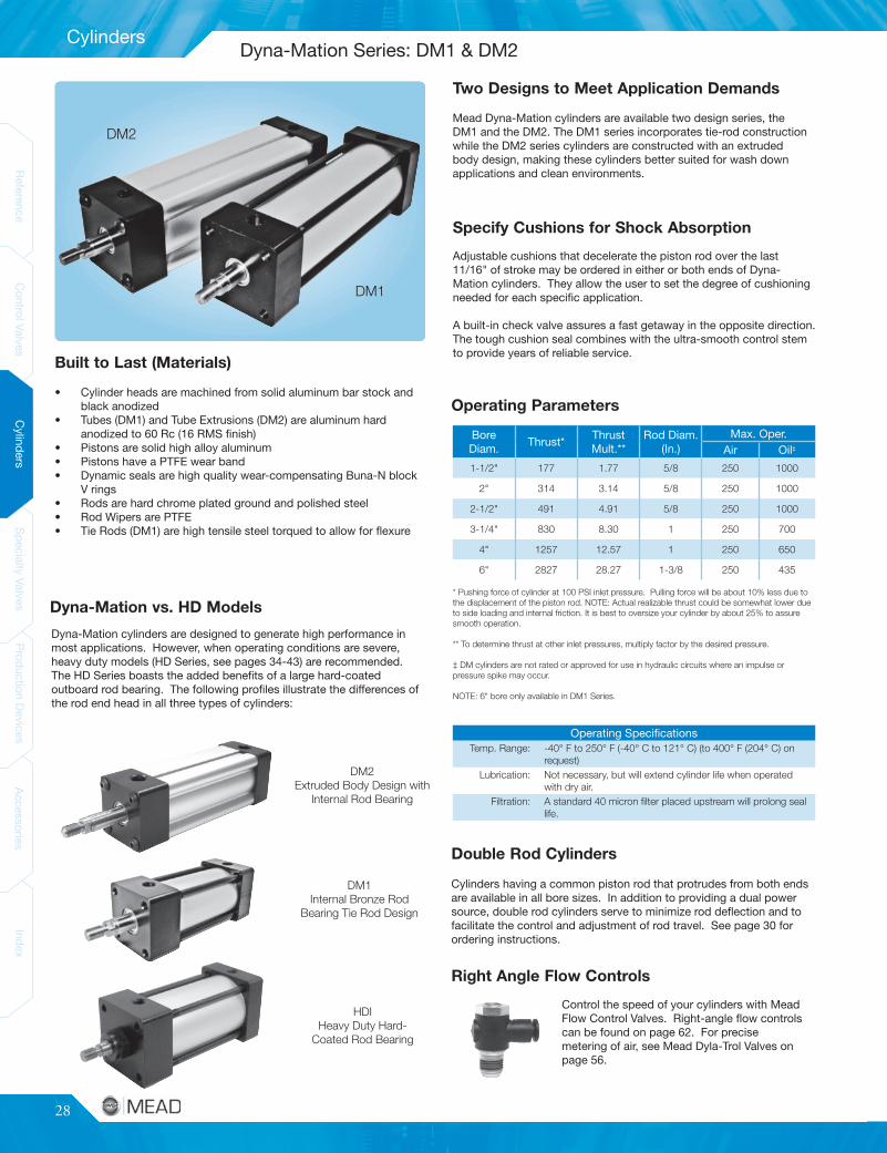
28
Cylinders
ReferenceControlValves
CylindersSpecialtyValves
ProductionDevices
AccessoriesIndex
ReferenceControlValves
CylindersSpecialtyValves
ProductionDevices
AccessoriesIndex
• Cylinder heads are machined from solid aluminum bar stock andblack anodized
• Tubes (DM1) and Tube Extrusions (DM2) are aluminum hardanodized to 60 Rc (16 RMS finish)
• Pistons are solid high alloy aluminum• Pistons have a PTFE wear band• Dynamic seals are high quality wear-compensating Buna-N block
V rings• Rods are hard chrome plated ground and polished steel• Rod Wipers are PTFE• Tie Rods (DM1) are high tensile steel torqued to allow for flexure
Operating SpecificationsTemp. Range: -40° F to 250° F (-40° C to 121° C) (to 400° F (204° C) on
request)Lubrication: Not necessary, but will extend cylinder life when operated
with dry air.Filtration: A standard 40 micron filter placed upstream will prolong seal
life.
BoreDiam.
Thrust*ThrustMult.**
Rod Diam.(In.)
Max. Oper.Air Oil‡
1-1/2" 177 1.77 5/8 250 1000
2" 314 3.14 5/8 250 1000
2-1/2" 491 4.91 5/8 250 1000
3-1/4" 830 8.30 1 250 700
4" 1257 12.57 1 250 650
6" 2827 28.27 1-3/8 250 435
Dyna-Mation cylinders are designed to generate high performance inmost applications. However, when operating conditions are severe,heavy duty models (HD Series, see pages 34-43) are recommended.The HD Series boasts the added benefits of a large hard-coatedoutboard rod bearing. The following profiles illustrate the differences ofthe rod end head in all three types of cylinders:
DM2Extruded Body Design with
Internal Rod Bearing
HDIHeavy Duty Hard-
Coated Rod Bearing
DM1Internal Bronze Rod
Bearing Tie Rod Design
DM1
DM2
Built to Last (Materials)
Operating Parameters
Specify Cushions for Shock Absorption
Two Designs to Meet Application Demands
Dyna-Mation vs. HD Models
Double Rod Cylinders
Right Angle Flow Controls
* Pushing force of cylinder at 100 PSI inlet pressure. Pulling force will be about 10% less due tothe displacement of the piston rod. NOTE: Actual realizable thrust could be somewhat lower dueto side loading and internal friction. It is best to oversize your cylinder by about 25% to assuresmooth operation.
** To determine thrust at other inlet pressures, multiply factor by the desired pressure.
‡ DM cylinders are not rated or approved for use in hydraulic circuits where an impulse orpressure spike may occur.
NOTE: 6" bore only available in DM1 Series.
Adjustable cushions that decelerate the piston rod over the last11/16" of stroke may be ordered in either or both ends of Dyna-Mation cylinders. They allow the user to set the degree of cushioningneeded for each specific application.
A built-in check valve assures a fast getaway in the opposite direction.The tough cushion seal combines with the ultra-smooth control stemto provide years of reliable service.
Mead Dyna-Mation cylinders are available two design series, theDM1 and the DM2. The DM1 series incorporates tie-rod constructionwhile the DM2 series cylinders are constructed with an extrudedbody design, making these cylinders better suited for wash downapplications and clean environments.
Cylinders having a common piston rod that protrudes from both endsare available in all bore sizes. In addition to providing a dual powersource, double rod cylinders serve to minimize rod deflection and tofacilitate the control and adjustment of rod travel. See page 30 forordering instructions.
Control the speed of your cylinders with MeadFlow Control Valves. Right-angle flow controlscan be found on page 62. For precisemetering of air, see Mead Dyla-Trol Valves onpage 56.
Dyna-Mation Series: DM1 & DM2
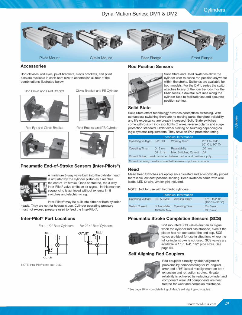
www.mead-usa.com #29
Inde
xAc
cess
ories
Prod
uctio
nDe
vices
Spec
ialty
Valve
sCy
linde
rsCo
ntrolV
alves
Referenc
e
Cylinders
Technical InformationOperating Voltage: 240 AC Max. Working Temp: 67° F to 200° F
(19° C to 93° C)Switch Current: .5 Amps Max. Operating Time: On .5 ms
10 Watts Max. Off .5 ms
Solid State and Reed Switches allow thecylinder user to sense rod position anywherewithin the stroke. Switches are available forboth models. For the DM1, series the switchattaches to any of the four tie-rods. For theDM2 series, a dovetail slot runs along thecylinder tube to facilitate fast and accurateposition setting.
Technical InformationOperating Voltage: 5-28 DC Working Temp: 23° F to 194° F
(-5° C to 90° C)Operating Time: On 2 ms Repeatability: .001 ms
Off .1 ms Max. Switching Current: .5ACurrent Sinking: Load connected between output and positive supply.
Current Sourcing: Load is connected between output and common.
Rod Clevis and Pivot Bracket Clevis Bracket and PE Cylinder
Rod Eye and Clevis Bracket Pivot Bracket and PB Cylinder
NOTE: Inter-Pilot®ports are 10-32.
For 1-1/2" Bore Cylinders For 2"-4" Bore Cylinders
Pivot Mount Clevis Mount Rear Flange Front Flange
Pneumatic End-of-Stroke Sensors (Inter-Pilots®)
Accessories Rod Position Sensors
Solid State
Reed
Pneumatic Stroke Completion Sensors (SCS)
Self Aligning Rod Couplers
Solid State effect technology provides contactless switching. Withcontactless switching there are no moving parts; therefore, reliabilityand life expectancy are greatly increased. Solid State switchescome with built-in indicator lights (3 wire), reverse polarity and surgeprotection standard. Order either sinking or sourcing depending onlogic systems requirements. They have an IP67 protection rating.
* See page 26 for complete listing of Mead’s self aligning rod couplers.
Rod couplers simplify cylinder alignmentproblems by compensating for 2ϒ angularerror and 1/16" lateral misalignment on bothextension and retraction strokes. Greaterreliability is achieved by reducing cylinder andcomponent wear. All components are heattreated for wear and corrosion resistance.
Port mounted SCS valves emit an air signalwhen the cylinder rod has stopped, even if thepiston has not contacted the end cap. SCSvalves are ideal for use in situations where thefull cylinder stroke is not used. SCS valves areavailable in 1/8", 1/4", 1/2" pipe sizes. Seepage 54.
Mead Reed Switches are epoxy encapsulated and economically pricedfor reliable low cost position sensing. Reed switches come with wireleads. LED (2 wire, 3m length) included.
NOTE: Not for use with hydraulic cylinders.
Rod clevises, rod eyes, pivot brackets, clevis brackets, and pivotpins are available in each bore size to accomplish all four of thecombinations illustrated below.
A miniature 3-way valve built into the cylinder headis actuated by the cylinder piston as it reachesthe end of its stroke. Once contacted, the 3-wayInter-Pilot® valve emits an air signal. In this manner,sequencing is achieved without external limitswitches and electric wiring.
Inter-Pilots® may be built into either or both cylinderheads. They are not for hydraulic use. Cylinder operating pressuremust not exceed pressure used to feed the Inter-Pilot®.
Dyna-Mation Series: DM1 & DM2
Inter-Pilot® Port Locations
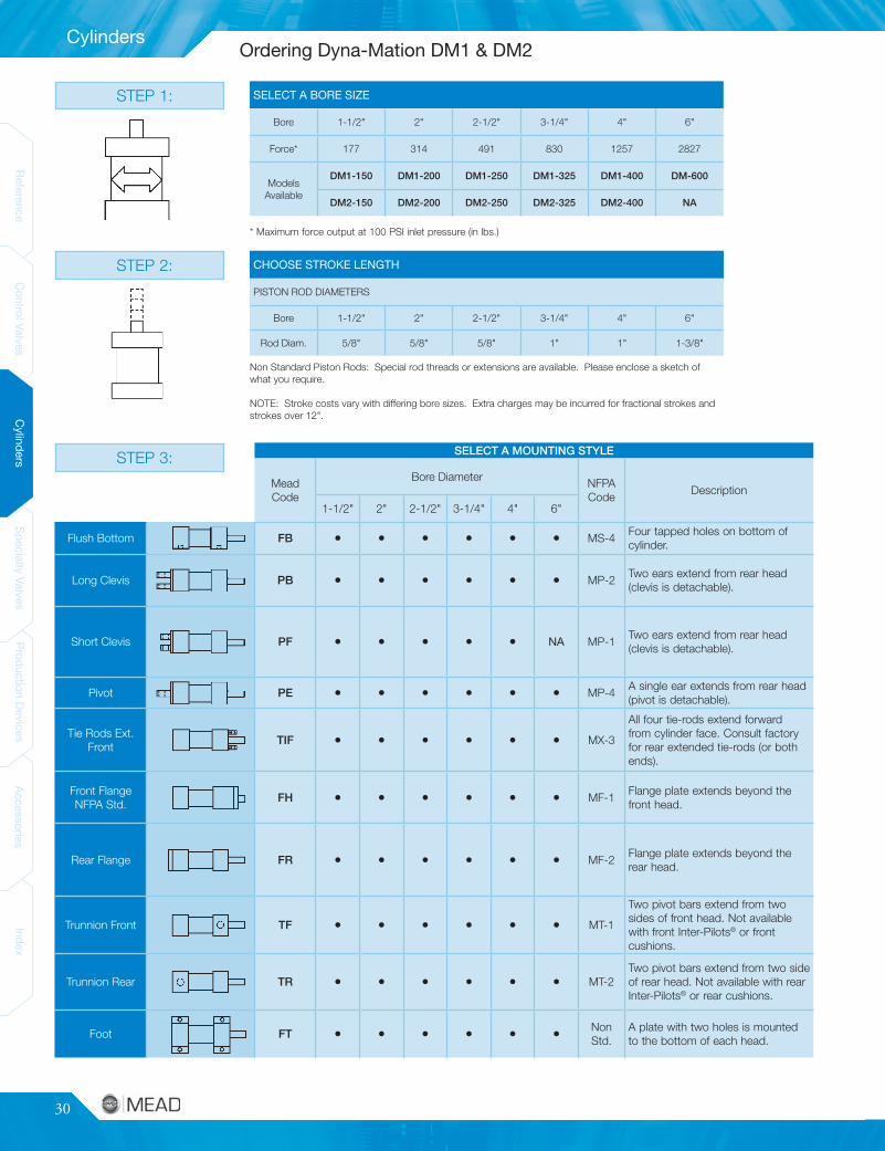
30
Cylinders
ReferenceControlValves
CylindersSpecialtyValves
ProductionDevices
AccessoriesIndex
ReferenceControlValves
CylindersSpecialtyValves
ProductionDevices
AccessoriesIndex
SELECT A MOUNTING STYLE
MeadCode
Bore Diameter NFPACode
Description
1-1/2" 2" 2-1/2" 3-1/4" 4" 6"
Flush Bottom FB • • • • • • MS-4Four tapped holes on bottom ofcylinder.
Long Clevis PB • • • • • • MP-2Two ears extend from rear head(clevis is detachable).
Short Clevis PF • • • • • NA MP-1Two ears extend from rear head(clevis is detachable).
Pivot PE • • • • • • MP-4A single ear extends from rear head(pivot is detachable).
Tie Rods Ext.Front
TIF • • • • • • MX-3
All four tie-rods extend forwardfrom cylinder face. Consult factoryfor rear extended tie-rods (or bothends).
Front FlangeNFPA Std.
FH • • • • • • MF-1Flange plate extends beyond thefront head.
Rear Flange FR • • • • • • MF-2Flange plate extends beyond therear head.
Trunnion Front TF • • • • • • MT-1
Two pivot bars extend from twosides of front head. Not availablewith front Inter-Pilots® or frontcushions.
Trunnion Rear TR • • • • • • MT-2Two pivot bars extend from two sideof rear head. Not available with rearInter-Pilots® or rear cushions.
Foot FT • • • • • • NonStd.
A plate with two holes is mountedto the bottom of each head.
STEP 3:
STEP 2:
SELECT A BORE SIZE
Bore 1-1/2" 2" 2-1/2" 3-1/4" 4" 6"
Force* 177 314 491 830 1257 2827
ModelsAvailable
DM1-150 DM1-200 DM1-250 DM1-325 DM1-400 DM-600
DM2-150 DM2-200 DM2-250 DM2-325 DM2-400 NA
Non Standard Piston Rods: Special rod threads or extensions are available. Please enclose a sketch ofwhat you require.
NOTE: Stroke costs vary with differing bore sizes. Extra charges may be incurred for fractional strokes andstrokes over 12".
Bore 1 1/2" 2" 2 1/2" 3 1/4" 4" 6"
Rod Diam. 5/8" 5/8" 5/8" 1" 1" 1 3/8"
CHOOSE STROKE LENGTHPISTON ROD DIAMETERS:
CHOOSE STROKE LENGTH
PISTON ROD DIAMETERS
Bore 1-1/2" 2" 2-1/2" 3-1/4" 4" 6"
Rod Diam. 5/8" 5/8" 5/8" 1" 1" 1-3/8"
* Maximum force output at 100 PSI inlet pressure (in lbs.)
STEP 1:
Ordering Dyna-Mation DM1 & DM2
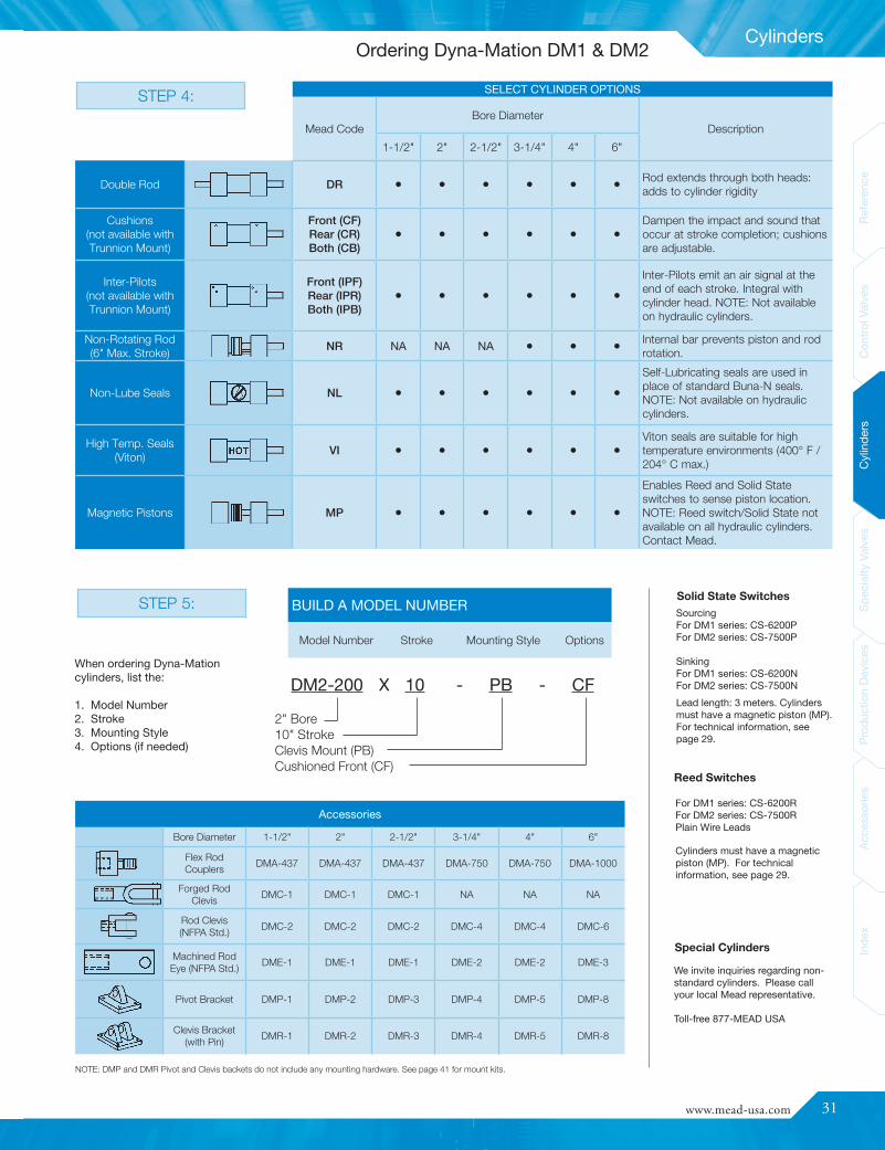
www.mead-usa.com #31
Inde
xAc
cess
ories
Prod
uctio
nDe
vices
Spec
ialty
Valve
sCy
linde
rsCo
ntrolV
alves
Referenc
e
Cylinders
We invite inquiries regarding non-standard cylinders. Please callyour local Mead representative.
Toll-free 877-MEAD USA
STEP 5:
SELECT CYLINDER OPTIONS
Mead CodeBore Diameter
Description
1-1/2" 2" 2-1/2" 3-1/4" 4" 6"
Double Rod DR • • • • • • Rod extends through both heads:adds to cylinder rigidity
Cushions(not available withTrunnion Mount)
Front (CF)Rear (CR)Both (CB)
• • • • • •Dampen the impact and sound thatoccur at stroke completion; cushionsare adjustable.
Inter-Pilots(not available withTrunnion Mount)
Front (IPF)Rear (IPR)Both (IPB)
• • • • • •
Inter-Pilots emit an air signal at theend of each stroke. Integral withcylinder head. NOTE: Not availableon hydraulic cylinders.
Non-Rotating Rod(6" Max. Stroke)
NR NA NA NA • • • Internal bar prevents piston and rodrotation.
Non-Lube Seals NL • • • • • •
Self-Lubricating seals are used inplace of standard Buna-N seals.NOTE: Not available on hydrauliccylinders.
High Temp. Seals(Viton)
VI • • • • • •Viton seals are suitable for hightemperature environments (400° F /204° C max.)
Magnetic Pistons MP • • • • • •
Enables Reed and Solid Stateswitches to sense piston location.NOTE: Reed switch/Solid State notavailable on all hydraulic cylinders.Contact Mead.
STEP 4:
BUILD A MODEL NUMBER
Model Number Stroke Mounting Style Options
DM2-200 X 10 - PB - CF
Solid State Switches
Cylinders must have a magneticpiston (MP). For technicalinformation, see page 29.
SourcingFor DM1 series: CS-6200PFor DM2 series: CS-7500P
SinkingFor DM1 series: CS-6200NFor DM2 series: CS-7500N
For DM1 series: CS-6200RFor DM2 series: CS-7500RPlain Wire Leads
Lead length: 3 meters. Cylindersmust have a magnetic piston (MP).For technical information, seepage 29.
Reed Switches
Special Cylinders
NOTE: DMP and DMR Pivot and Clevis backets do not include any mounting hardware. See page 41 for mount kits.
Accessories
Bore Diameter 1-1/2" 2" 2-1/2" 3-1/4" 4" 6"
Flex RodCouplers
DMA-437 DMA-437 DMA-437 DMA-750 DMA-750 DMA-1000
Forged RodClevis
DMC-1 DMC-1 DMC-1 NA NA NA
Rod Clevis(NFPA Std.)
DMC-2 DMC-2 DMC-2 DMC-4 DMC-4 DMC-6
Machined RodEye (NFPA Std.)
DME-1 DME-1 DME-1 DME-2 DME-2 DME-3
Pivot Bracket DMP-1 DMP-2 DMP-3 DMP-4 DMP-5 DMP-8
Clevis Bracket(with Pin)
DMR-1 DMR-2 DMR-3 DMR-4 DMR-5 DMR-8
When ordering Dyna-Mationcylinders, list the:
1. Model Number2. Stroke3. Mounting Style4. Options (if needed)
2" Bore10" StrokeClevis Mount (PB)Cushioned Front (CF)
Ordering Dyna-Mation DM1 & DM2

32
Cylinders
ReferenceControlValves
CylindersSpecialtyValves
ProductionDevices
AccessoriesIndex
ReferenceControlValves
CylindersSpecialtyValves
ProductionDevices
AccessoriesIndex
Basic Cylinder
Bottom Flush Model FB
Rod End Trunnion Model TF
Clevis Model PB and PF
Rod End Flange Model FH*
Pivot Model PE
Foot Mount Plate Model FT
Blind End Trunnion Model TR1
Double Rod Model DR
Port Locations
1
3
24
NOTE: DM1 cylinders are constructed with sleeve nuts. For DM1, use RT;K does not exist. For DM2, use K; RT does not exist.
Blind End Flange Model FR*
NOTE: For dimensions of nose mount and tie rod extended models, consult factory.
DM1 & DM2 Dimensions
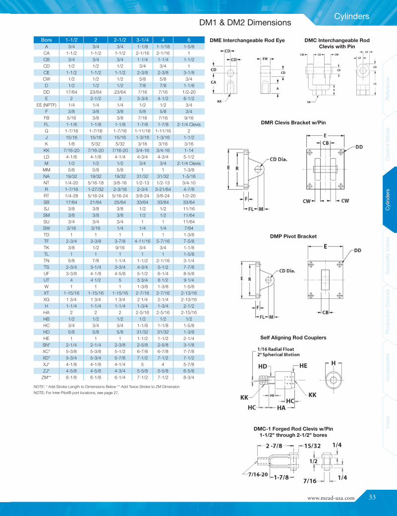
www.mead-usa.com #33
Inde
xAc
cess
ories
Prod
uctio
nDe
vices
Spec
ialty
Valve
sCy
linde
rsCo
ntrolV
alves
Referenc
e
Cylinders
DME Interchangeable Rod Eye DMC Interchangeable RodClevis with Pin
DMR Clevis Bracket w/Pin
DMP Pivot Bracket
Self Aligning Rod Couplers
DMC-1 Forged Rod Clevis w/Pin1-1/2" through 2-1/2" bores
Bore 1-1/2 2 2-1/2 3-1/4 4 6A 3/4 3/4 3/4 1-1/8 1-1/18 1-5/8
CA 1-1/2 1-1/2 1-1/2 2-1/16 2-1/16 1CB 3/4 3/4 3/4 1-1/4 1-1/4 1-1/2CD 1/2 1/2 1/2 3/4 3/4 1CE 1-1/2 1-1/2 1-1/2 2-3/8 2-3/8 3-1/8CW 1/2 1/2 1/2 5/8 5/8 3/4D 1/2 1/2 1/2 7/8 7/8 1-1/8
DD 17/64 23/64 23/64 7/16 7/16 1/2-20E 2 2-1/2 3 3-3/4 4-1/2 6-1/2
EE (NPTF) 1/4 1/4 1/4 1/2 1/2 3/4F 3/8 3/8 3/8 5/8 5/8 3/4
FB 5/16 3/8 3/8 7/16 7/16 9/16FL 1-1/8 1-1/8 1-1/8 1-7/8 1-7/8 2-1/4 ClevisG 1-7/16 1-7/16 1-7/16 1-11/16 1-11/16 2J 15/16 15/16 15/16 1-3/16 1-3/16 1-1/2K 1/8 5/32 5/32 3/16 3/16 3/16
KK 7/16-20 7/16-20 7/16-20 3/4-16 3/4-16 1-14LD 4-1/8 4-1/8 4-1/4 4-3/4 4-3/4 5-1/2M 1/2 1/2 1/2 3/4 3/4 2-1/4 Clevis
MM 5/8 5/8 5/8 1 1 1-3/8NA 19/32 19/32 19/32 31/32 31/32 1-5/16NT 1/4-20 5/16-18 3/8-16 1/2-13 1/2-13 3/4-10R 1-7/16 1-27/32 2-3/16 2-3/4 3-21/64 4-7/8
RT 1/4-28 5/16-24 5/16-24 3/8-24 3/8-24 1/2-20SB 17/64 21/64 25/64 33/64 33/64 33/64SJ 3/8 3/8 3/8 1/2 1/2 11/16SM 3/8 3/8 3/8 1/2 1/2 11/64SU 3/4 3/4 3/4 1 1 11/64SW 3/16 3/16 1/4 1/4 1/4 7/64TD 1 1 1 1 1 1-3/8TF 2-3/4 3-3/8 3-7/8 4-11/16 5-7/16 7-5/8TK 3/8 1/2 9/16 3/4 3/4 1-1/8TL 1 1 1 1 1 1-5/8TN 5/8 7/8 1-1/4 1-1/2 2-1/16 3-1/4TS 2-3/4 3-1/4 3-3/4 4-3/4 5-1/2 7-7/8UF 3-3/8 4-1/8 4-5/8 5-1/2 6-1/4 8-5/8UT 4 4 1/2 5 5 3/4 6 1/2 9 1/4W 1 1 1 1-3/8 1-3/8 1-5/8XT 1-15/16 1-15/16 1-15/16 2-7/16 2-7/16 2-13/16XG 1 3/4 1 3/4 1 3/4 2 1/4 2-1/4 2-13/16H 1-1/4 1-1/4 1-1/4 1-3/4 1-3/4 2-1/2
HA 2 2 2 2-5/16 2-5/16 2-15/16HB 1/2 1/2 1/2 1/2 1/2 1/2HC 3/4 3/4 3/4 1-1/8 1-1/8 1-5/8HD 5/8 5/8 5/8 31/32 31/32 1-3/8HE 1 1 1 1-1/2 1-1/2 2-1/4SN* 2-1/4 2-1/4 2-3/8 2-5/8 2-5/8 3-1/8XC* 5-3/8 5-3/8 5-1/2 6-7/8 6-7/8 7-7/8XD* 5-3/4 5-3/4 5-7/8 7-1/2 7-1/2 7-1/2XJ* 4-1/8 4-1/8 4-1/4 5 4 5-7/8ZJ* 4-5/8 4-5/8 4-3/4 5-5/8 5-5/8 6-5/8
ZM** 6-1/8 6-1/8 6-1/4 7-1/2 7-1/2 8-3/4
NOTE: * Add Stroke Length to Dimensions Below ** Add Twice Stroke to ZM DimensionNOTE: For Inter-Pilot® port locations, see page 27.
DM1 & DM2 Dimensions

34
Cylinders
ReferenceControlValves
CylindersSpecialtyValves
ProductionDevices
AccessoriesIndex
ReferenceControlValves
CylindersSpecialtyValves
ProductionDevices
AccessoriesIndex
BoreDiam.
Thrust*ThrustMult.**
Rod Diam.Max. Oper. Pressure
Air Oil ‡
1-1/2" 177 1.77 5/8" or 1" 250 10002" 314 3.14 5/8" or 1" 250 1000
2-1/2" 491 4.91 5/8" or 1" 250 10003-1/4" 830 8.30 1" or 1-3/8" 250 700
4" 1257 12.57 1" or 1-3/8" 250 6506" 2827 28.27 1-3/8" or 1-3/4" 250 435
Operating SpecificationsTemperature Range: -40° F to 250° F (-40° C to 121° C) (to 400° [204° C]
F on request)Lubrication: For maximum cylinder life, non-detergent petroleum-
based oil is recommended. Non-lube seals available.Filtration: Not essential, but a standard 40 micron filter placed
upstream will prolong seal life.
Cylinder Construction
External Bearing Ensures Smooth MotionHD1 cylinders are fitted with a heavy-duty external rod bearing in therod end head. Teflon-impregnated and hardcoat anodized, this bearingensures smooth rod motion while maintaining rod rigidity and stability.The entire rod gland and bearing may be quickly removed and replacedwithout disassembling the cylinder.
Cylinders For Abusive Conditions
* Pushing force of cylinder at 100 PSI inlet pressure. Pulling force will be about10% less due to the displacement of the piston rod. NOTE: Actual realizable thrustcould be somewhat lower due to side loading and internal friction. It is best tooversize your cylinder by about 25% to assure smooth operation.
** To determine cylinder thrust at other inlet pressures, multiply this factor times thedesired inlet pressure.
‡HD1 Cylinders are not rated or approved for use in a hydraulic circuits where animpulse or pressure spike may occur.
Operating Parameters
Rod Bearing:Teflon-impregnated, hardcoated aluminum
Heads:Machined from solid aluminum bar; black anodized
Tubes:Aluminum hard anodized to 60 Rc (16 RMS finish)
Piston:Solid high alloy aluminum and fitted with a PTFE Wear Band.
Piston Rod:High tensile ground and polished hard chrome plated steel
Piston and Rod Seals:Wear compensating Buna-N vee rings. Non-lube seals are alsoavailable (see Option NL).
Tube Seals:Buna-N O-rings
Rod Wiper:Dupont Teflon®
Tie Rods:High tensile steel torqued to allow for flexure.
NOTE: 6" Bore Cylinders do not have wear bands. (HD)
Combining NFPA dimensional interchangeability and high qualitycomponents, the “HD1” Series offers excellent performance and longservice life, even in the most severe of conditions.
HD1 Cylinders

www.mead-usa.com #35
Inde
xAc
cess
ories
Prod
uctio
nDe
vices
Spec
ialty
Valve
sCy
linde
rsCo
ntrolV
alves
Referenc
e
Cylinders
Bore (Either Head) 1-1/2" 2" 2-1/2" 3-1/4" 4" 6"Non-Cushion 2 1 1 1 1 3Cushion 2 1 1 1 1 3
Dyla-Trol® - For unprecedented smoothness incylinder speed control, use Mead’s Dyla-Trol®valves with a perfectly tapering flow. Whereneedle type flow controls generate turbulenceas they close, Dyla-Trol® maintains an even 360laminar flow regardless of the setting. See page56 for more information.
Right Angle Flow Controls (RAF) - RAF flowcontrols feature push-in-fittings, pre-appliedTeflon® based thread sealant, a recessed screwdriver adjustment and convenient swivel for easeof tubing alignment. See page 62.
For prevention of piston and rod rotation, an internal rod is embeddedinternally into both cylinder heads. This rod also passes through thepiston and acts as a linear guide for the piston. NOTE: NR optionavailable on 3-1/4", 4" and 6" bore cylinders only.
Accessories
STYLE 1 STYLE 2 STYLE 3
See page 26 for complete listing of Mead’s self aligning rod couplers.
Inter-Pilots® (IP)
Pneumatic Stroke Completion Sensors (SCS)
Self Aligning Rod Couplers
Flow Control Valves
Customize Your Cylinder
Cushions (CR, CF, CB)
Double Rod (DR)
Non-Rotating Rod (NR)
Viton™ Seals (VI)
Low Breakaway Option (NL)
Magnetic Piston (MP)
Oversized Rod (OR)
The HD1 Series offers numerous accessories and design options. Withhundreds of possible combinations available, you can “design” your owncylinder for any application.
For end-of-stroke load deceleration, specify cushions in either or bothends of your cylinder. Cushions decelerate the piston rod over thelast 11/16" of stroke. Adjustable, they allow you to set the degree ofcushioning needed for each specific application.
A built-in check valve assures a fast getaway in the opposite direction. Apre-lubricated nitrile cushion seal provides years of reliable service.
NOTE: Cushions are not recommended on hydraulic cylinders.
For high temperature environments, Viton™ seals can be specified toreplace standard Buna-N seals. While HD1 cylinders are normally ratedto 250° F (121° C), cylinders with Viton seals are rated to 400° F (204°C).
For non-lube service, polyurethane seals replace standard piston androd seals. These specially formulated seals have an inherent lubricitythat provides low breakaway between the piston and tube. NOTE: NLseals are not available on hydraulic cylinders.
If you will be using either Solid State or Reed switches for sensing rodposition, you will need to order your cylinder with a magnetic piston.
Mead’s Solid State and Reed switches allow the cylinder user to senserod position anywhere within the stroke. They emit an electrical signalwhen the magnetized piston reaches a point opposite their location. Tierod mounting facilitates fast and accurate position setting.
Double rod cylinders have a common piston rod that protrudes fromboth ends of the cylinder. In addition to providing a dual power source,double rod cylinders serve to minimize rod deflection and to facilitate thecontrol and adjustment of rod travel.
Available on all models: on the HD1-150, 200 and 250, you can ordera 1" rod diameter rather than the standard 5/8" diameter; the HD1-325and HD1-400 with a 1-3/8" rather than the standard 1"; and the HD1-600 with a 1-3/4" rather than the standard 1-3/8".
Mead’s Inter-Pilot® is a miniature 3-way valvebuilt in the cylinder head. Actuated by thecylinder’s piston as it reaches the end of itsstroke, the valve emits an air signal. Thus,sequencing is achieved without external limitswitches and electric wiring.
Inter-Pilots may be built into either or bothcylinder heads. They are not for hydraulicuse. Cylinder operating pressure must notexceed pressure used to feed the Inter-Pilot®.
INTER-PILOT® PORT LOCATIONS (Port Size = 10-32): Inter-Pilot portlocation style that is offered with each cylinder head.
Port mounted SCS valves emit an air signal when the cylinder rod hasstopped, even if the piston has not contacted the end cap. Ideal for usein situations where the full cylinder stroke is not used. See page 54.
Rod couplers simplify cylinder alignment problemsby compensating for 2° angular error and 1/16"lateral misalignment on both extension andretraction strokes. Greater reliability is achievedby reducing cylinder and component wear. Allcomponents are heat treated for wear and corrosionresistance.
HD1 Cylinders
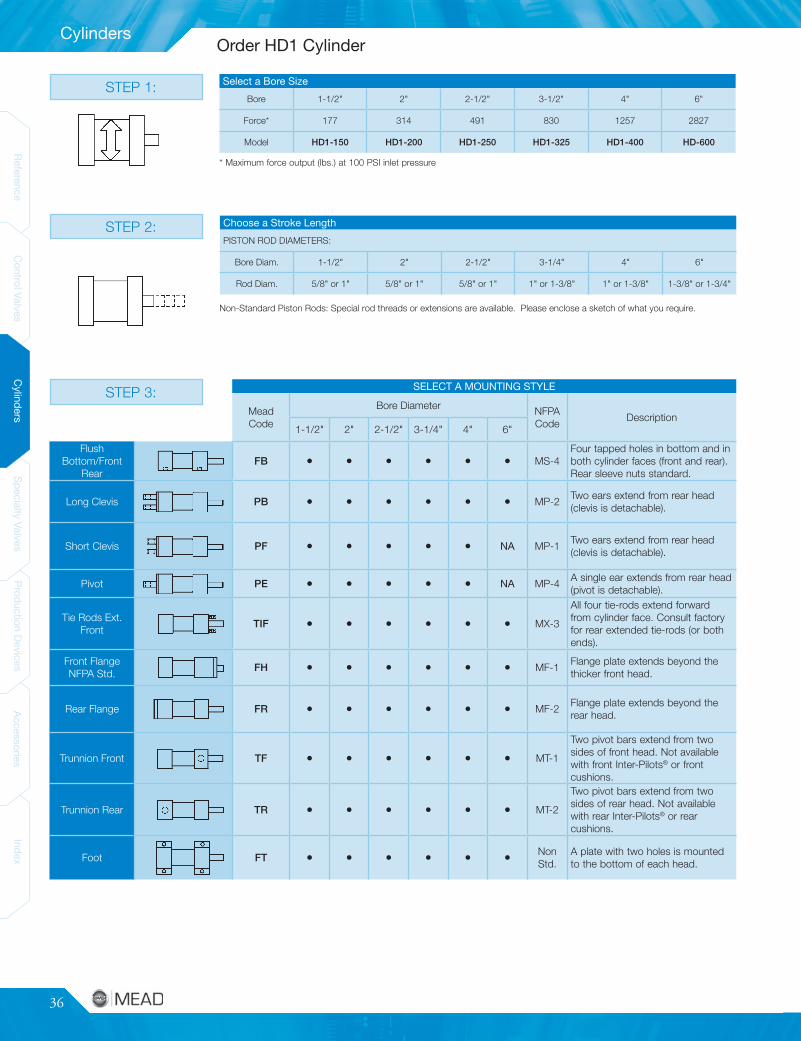
36
Cylinders
ReferenceControlValves
CylindersSpecialtyValves
ProductionDevices
AccessoriesIndex
ReferenceControlValves
CylindersSpecialtyValves
ProductionDevices
AccessoriesIndex
STEP 2:
STEP 1:
SELECT A MOUNTING STYLE
MeadCode
Bore Diameter NFPACode
Description1-1/2" 2" 2-1/2" 3-1/4" 4" 6"
FlushBottom/Front
RearFB • • • • • • MS-4
Four tapped holes in bottom and inboth cylinder faces (front and rear).Rear sleeve nuts standard.
Long Clevis PB • • • • • • MP-2Two ears extend from rear head(clevis is detachable).
Short Clevis PF • • • • • NA MP-1Two ears extend from rear head(clevis is detachable).
Pivot PE • • • • • NA MP-4A single ear extends from rear head(pivot is detachable).
Tie Rods Ext.Front
TIF • • • • • • MX-3
All four tie-rods extend forwardfrom cylinder face. Consult factoryfor rear extended tie-rods (or bothends).
Front FlangeNFPA Std.
FH • • • • • • MF-1Flange plate extends beyond thethicker front head.
Rear Flange FR • • • • • • MF-2Flange plate extends beyond therear head.
Trunnion Front TF • • • • • • MT-1
Two pivot bars extend from twosides of front head. Not availablewith front Inter-Pilots® or frontcushions.
Trunnion Rear TR • • • • • • MT-2
Two pivot bars extend from twosides of rear head. Not availablewith rear Inter-Pilots® or rearcushions.
Foot FT • • • • • • NonStd.
A plate with two holes is mountedto the bottom of each head.
Choose a Stroke Length
PISTON ROD DIAMETERS:
Bore Diam. 1-1/2" 2" 2-1/2" 3-1/4" 4" 6"
Rod Diam. 5/8" or 1" 5/8" or 1" 5/8" or 1" 1" or 1-3/8" 1" or 1-3/8" 1-3/8" or 1-3/4"
Select a Bore Size
Bore 1-1/2" 2" 2-1/2" 3-1/2" 4" 6"
Force* 177 314 491 830 1257 2827
Model HD1-150 HD1-200 HD1-250 HD1-325 HD1-400 HD-600
* Maximum force output (lbs.) at 100 PSI inlet pressure
Non-Standard Piston Rods: Special rod threads or extensions are available. Please enclose a sketch of what you require.
STEP 3:
Order HD1 Cylinder
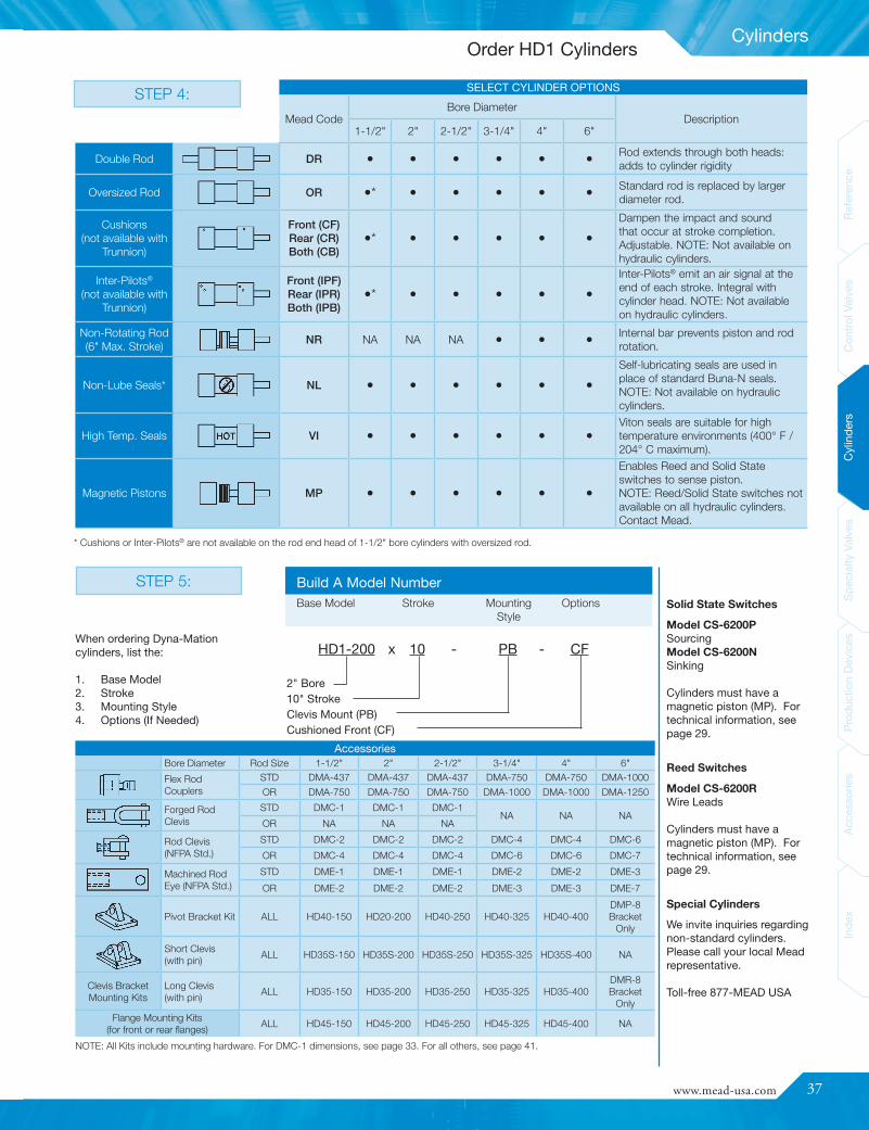
www.mead-usa.com #37
Inde
xAc
cess
ories
Prod
uctio
nDe
vices
Spec
ialty
Valve
sCy
linde
rsCo
ntrolV
alves
Referenc
e
Cylinders
STEP 5:
AccessoriesBore Diameter Rod Size 1-1/2" 2" 2-1/2" 3-1/4" 4" 6"
Flex RodCouplers
STD DMA-437 DMA-437 DMA-437 DMA-750 DMA-750 DMA-1000
OR DMA-750 DMA-750 DMA-750 DMA-1000 DMA-1000 DMA-1250
Forged RodClevis
STD DMC-1 DMC-1 DMC-1NA NA NA
OR NA NA NA
Rod Clevis(NFPA Std.)
STD DMC-2 DMC-2 DMC-2 DMC-4 DMC-4 DMC-6
OR DMC-4 DMC-4 DMC-4 DMC-6 DMC-6 DMC-7
Machined RodEye (NFPA Std.)
STD DME-1 DME-1 DME-1 DME-2 DME-2 DME-3
OR DME-2 DME-2 DME-2 DME-3 DME-3 DME-7
Pivot Bracket Kit ALL HD40-150 HD20-200 HD40-250 HD40-325 HD40-400DMP-8Bracket
Only
Short Clevis(with pin)
ALL HD35S-150 HD35S-200 HD35S-250 HD35S-325 HD35S-400 NA
Clevis BracketMounting Kits
Long Clevis(with pin)
ALL HD35-150 HD35-200 HD35-250 HD35-325 HD35-400DMR-8Bracket
OnlyFlange Mounting Kits
(for front or rear flanges)ALL HD45-150 HD45-200 HD45-250 HD45-325 HD45-400 NA
Reed SwitchesModel CS-6200RWire Leads
Cylinders must have amagnetic piston (MP). Fortechnical information, seepage 29.
Model CS-6200PSourcingModel CS-6200NSinking
Cylinders must have amagnetic piston (MP). Fortechnical information, seepage 29.
Solid State Switches
SELECT CYLINDER OPTIONS
Mead CodeBore Diameter
Description1-1/2" 2" 2-1/2" 3-1/4" 4" 6"
Double Rod DR • • • • • • Rod extends through both heads:adds to cylinder rigidity
Oversized Rod OR •* • • • • • Standard rod is replaced by largerdiameter rod.
Cushions(not available with
Trunnion)
Front (CF)Rear (CR)Both (CB)
•* • • • • •
Dampen the impact and soundthat occur at stroke completion.Adjustable. NOTE: Not available onhydraulic cylinders.
Inter-Pilots®
(not available withTrunnion)
Front (IPF)Rear (IPR)Both (IPB)
•* • • • • •
Inter-Pilots® emit an air signal at theend of each stroke. Integral withcylinder head. NOTE: Not availableon hydraulic cylinders.
Non-Rotating Rod(6" Max. Stroke)
NR NA NA NA • • • Internal bar prevents piston and rodrotation.
Non-Lube Seals* NL • • • • • •
Self-lubricating seals are used inplace of standard Buna-N seals.NOTE: Not available on hydrauliccylinders.
High Temp. Seals VI • • • • • •Viton seals are suitable for hightemperature environments (400° F /204° C maximum).
Magnetic Pistons MP • • • • • •
Enables Reed and Solid Stateswitches to sense piston.NOTE: Reed/Solid State switches notavailable on all hydraulic cylinders.Contact Mead.
Build A Model NumberBase Model Stroke Mounting Options
Style
HD1-200 x 10 - PB - CF
2" Bore10" StrokeClevis Mount (PB)Cushioned Front (CF)
* Cushions or Inter-Pilots® are not available on the rod end head of 1-1/2" bore cylinders with oversized rod.
When ordering Dyna-Mationcylinders, list the:
1. Base Model2. Stroke3. Mounting Style4. Options (If Needed)
Special CylindersWe invite inquiries regardingnon-standard cylinders.Please call your local Meadrepresentative.
Toll-free 877-MEAD USA
NOTE: All Kits include mounting hardware. For DMC-1 dimensions, see page 33. For all others, see page 41.
STEP 4:
Order HD1 Cylinders

38
Cylinders
ReferenceControlValves
CylindersSpecialtyValves
ProductionDevices
AccessoriesIndex
ReferenceControlValves
CylindersSpecialtyValves
ProductionDevices
AccessoriesIndex
BORE MM ROD DIA. NT RT TK TN SN XT
1-1/25/8
1/4-20 1/4-28 3/8 5/8 2-1/41-15/16
1 2 - 5/16
25/8
5/16-18 5/16-24 1/2 7/8 2-1/41-15/16
1 2-5/16
2-1/25/8
3/8-16 5/16-24 9/16 1-1/4 2-3/81-15/16
1 2-5/16
3-1/41
1/2-13 3/8-24 3/4 1-1/2 2-5/82-7/16
1-3/8 2-11/16
41
1/2-13 3/8-24 3/4 2-1/16 2-5/82-7/16
1-3/8 2-11/16
61-3/8
3/4-10 1/2-20 1-1/8 3-1/4 3-1/82-13/16
1-3/4 3-3/16
BOREMMROD
A B C D E EE F G J K KK LAF LB LD P R WF Y ZS ZM RD
1-1/25/8 3/4 1-1/8 3/8 1/2
2 1/4 3/8 1-7/16 15/16 -7/16-20 1-3/4
3-5/8 4-1/8 2-1/4 1-7/161 1-15/16
1-1/46-1/8 1-1/8
1 1-1/8 1-1/2 5/8 7/8 3/4-16 2-1/2 1-3/8 2-5/16 6-1/2 1-1/2
25/8 3/4 1-1/8 3/8 1/2
2-1/2 1/4 3/8 1-7/16 15/16 -7/16-20 1-3/4
3-5/8 4-1/8 2-1/4 1-27/321 1-15/16
1-1/46-1/8 1-1/8
1 1-1/8 1-1/2 5/8 7/8 3/4-16 2-1/2 1-3/8 2-5/16 6-1/2 1-1/2
2-1/25/8 3/4 1-1/8 3/8 1/2
3 1/4 3/8 1-7/16 15/16 -7/16-20 1-3/4
3-3/4 4-1/4 2-3/8 2-3/161 1-15/16
1-3/86-1/4 1-1/8
1 1-1/8 1-1/2 5/8 7/8 3/4-16 2-1/2 1-3/8 2-5/16 6-5/8 1-1/2
3-1/41 1-1/8 1-1/2 3/8 7/8
3-3/4 1/2 5/8 1-11/16 1-3/16 -3/4-16 2-1/2
4-1/2 4-3/4 2-5/8 2-3/41-3/8 2-7/16
1-3/87-1/2 1-3/4
1-3/8 1-5/8 2 1/2 1-1/8 1-14 3-1/4 1-5/8 2-11/16 7-3/4 2
41 1-1/8 1-1/2 1/2 7/8
4-1/2 1/2 5/8 1-11/16 1-3/16 -3/4-16 2-1/2
4-1/2 4-3/4 2-5/8 3-21/641-3/8 2-7/16
1-3/87-1/2 1-3/4
1-3/8 1-5/8 2 5/8 1-1/8 1-14 3-1/4 1-5/8 2-11/16 7-3/4 2
61-3/8 1-5/8 2 5/8 1-1/8
6-1/2 3/4 3/4 2 1-1/2 7/161-14 3-1/4
5 5-1/2 3-1/8 4-7/81-5/8 2-13/16
1-1/28-3/4 2
1-3/4 2 2-3/8 3/4 1-1/2 1-1/4-12 3-7/8 1-7/8 3-1/16 9 2-3/8
Rear, Front & Bottom Tapped (FB) NFPA: MS4
* 6" bore HD cylinders have a rear tie rod nut, shown below as the ”K” dimension. K = 7/16"
Double Rod NFPA: MDX0Basic Cylinder NFPA: MX0
• EE Dimension is NPTF
HD1 Dimensions

www.mead-usa.com #39
Inde
xAc
cess
ories
Prod
uctio
nDe
vices
Spec
ialty
Valve
sCy
linde
rsCo
ntrolV
alves
Referenc
e
Cylinders
BOREMM ROD
DIA.CB CD CW FL L M XC XD
1-1/25/8
3/4 1/2 1/2 1-1/8 3/4 1/25-3/8 5-3/4
1 5 - 3 /4 6-1/8
25/8
3/4 1/2 1/2 1-1/8 3/4 1/25-3/8 5-3/4
1 5-3/4 6-1/8
2-1/25/8
3/4 1/2 1/2 1-1/8 3/4 1/25-1/2 5-7/8
1 5-7/8 6-1/4
3-1/41
1-1/4 3/4 5/8 1-7/8 1-1/4 3/46-7/8 7-1/2
1-3/8 7-1/8 5-3/4
41
1-1/4 3/4 5/8 1-7/8 1-1/4 3/46-7/8 7-1/2
1-3/8 7-1/8 7-3/4
61-3/8
1-1/2 1 3/4 2-1/4 Clevis - 1-1/8 Clevis NA8-7/8
1-3/4 9-1/8
BOREMM ROD
DIA.E FB (BOLT) FH R TF UF W ZJ ZF
1-1/25/8
2 5/16 3/8 1-7/16 2-3/4 3-3/85/8 4-5/8 5
1 1 5 5-3/8
25/8
2-1/2 3/8 3/8 1-27/32 3-3/8 4-1/85/8 4-5/8 5
1 1 5 5-3/8
2-1/25/8
3 3/8 3/8 2-3/16 3-7/8 4-5/85/8 4-3/4 5-1/8
1 1 5-1/8 5-1/2
3-1/41
3-3/4 7/16 5/8 2-3/4 4-11/16 5-1/23/4 5-5/8 6-1/4
1-3/8 1 5-7/8 6-1/2
41
4-1/2 7/16 5/8 3-21/64 5-7/16 6-1/43/4 5-5/8 6-1/4
1-3/8 1 5-7/8 6-1/2
61-3/8
6-1/2 9/16 3/4 4-7/8 7-5/8 8-5/87/8 6-5/8 7-3/8
1-3/4 1-1/8 6-7/8 7-5/8
Front Flange (FH) NFPA: MF1
Short Clevis (PF) NFPA: MP1 Long Clevis (PB) NFPA: MP2
Rear Flange (FR) NFPA: MF2
Pivot (PE) NFPA: MP4
HD1 Dimensions
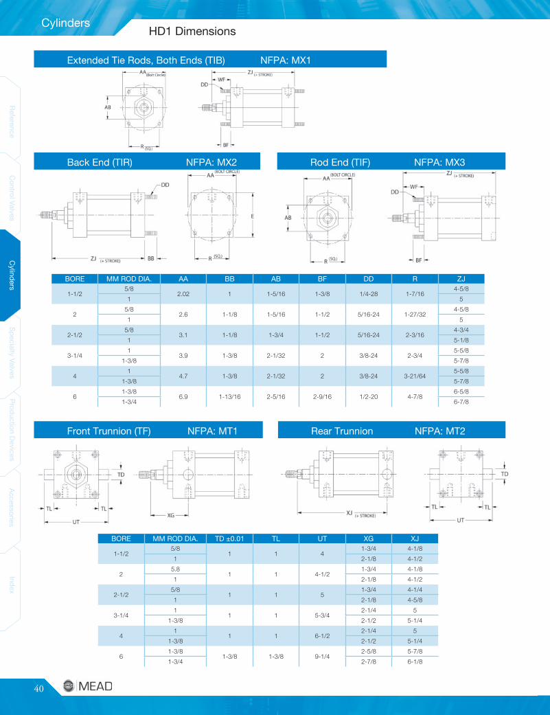
40
Cylinders
ReferenceControlValves
CylindersSpecialtyValves
ProductionDevices
AccessoriesIndex
ReferenceControlValves
CylindersSpecialtyValves
ProductionDevices
AccessoriesIndex
Rod End (TIF) NFPA: MX3Back End (TIR) NFPA: MX2
Rear Trunnion NFPA: MT2Front Trunnion (TF) NFPA: MT1
Extended Tie Rods, Both Ends (TIB) NFPA: MX1
BORE MM ROD DIA. AA BB AB BF DD R ZJ
1-1/25/8
2.02 1 1-5/16 1-3/8 1/4-28 1-7/164-5/8
1 5
25/8
2.6 1-1/8 1-5/16 1-1/2 5/16-24 1-27/324-5/8
1 5
2-1/25/8
3.1 1-1/8 1-3/4 1-1/2 5/16-24 2-3/164-3/4
1 5-1/8
3-1/41
3.9 1-3/8 2-1/32 2 3/8-24 2-3/45-5/8
1-3/8 5-7/8
41
4.7 1-3/8 2-1/32 2 3/8-24 3-21/645-5/8
1-3/8 5-7/8
61-3/8
6.9 1-13/16 2-5/16 2-9/16 1/2-20 4-7/86-5/8
1-3/4 6-7/8
BORE MM ROD DIA. TD ±0.01 TL UT XG XJ
1-1/25/8
1 1 41-3/4 4-1/8
1 2-1/8 4-1/2
25.8
1 1 4-1/21-3/4 4-1/8
1 2-1/8 4-1/2
2-1/25/8
1 1 51-3/4 4-1/4
1 2-1/8 4-5/8
3-1/41
1 1 5-3/42-1/4 5
1-3/8 2-1/2 5-1/4
41
1 1 6-1/22-1/4 5
1-3/8 2-1/2 5-1/4
61-3/8
1-3/8 1-3/8 9-1/42-5/8 5-7/8
1-3/4 2-7/8 6-1/8
HD1 Dimensions
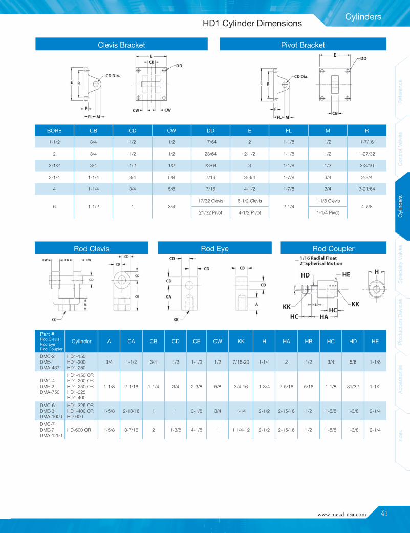
www.mead-usa.com #41
Inde
xAc
cess
ories
Prod
uctio
nDe
vices
Spec
ialty
Valve
sCy
linde
rsCo
ntrolV
alves
Referenc
e
Cylinders
Part #Rod ClevisRod EyeRod Coupler
Cylinder A CA CB CD CE CW KK H HA HB HC HD HE
DMC-2DME-1DMA-437
HD1-150HD1-200HD1-250
3/4 1-1/2 3/4 1/2 1-1/2 1/2 7/16-20 1-1/4 2 1/2 3/4 5/8 1-1/8
DMC-4DME-2DMA-750
HD1-150 ORHD1-200 ORHD1-250 ORHD1-325HD1-400
1-1/8 2-1/16 1-1/4 3/4 2-3/8 5/8 3/4-16 1-3/4 2-5/16 5/16 1-1/8 31/32 1-1/2
DMC-6DME-3DMA-1000
HD1-325 ORHD1-400 ORHD-600
1-5/8 2-13/16 1 1 3-1/8 3/4 1-14 2-1/2 2-15/16 1/2 1-5/8 1-3/8 2-1/4
DMC-7DME-7DMA-1250
HD-600 OR 1-5/8 3-7/16 2 1-3/8 4-1/8 1 1 1/4-12 2-1/2 2-15/16 1/2 1-5/8 1-3/8 2-1/4
BORE CB CD CW DD E FL M R
1-1/2 3/4 1/2 1/2 17/64 2 1-1/8 1/2 1-7/16
2 3/4 1/2 1/2 23/64 2-1/2 1-1/8 1/2 1-27/32
2-1/2 3/4 1/2 1/2 23/64 3 1-1/8 1/2 2-3/16
3-1/4 1-1/4 3/4 5/8 7/16 3-3/4 1-7/8 3/4 2-3/4
4 1-1/4 3/4 5/8 7/16 4-1/2 1-7/8 3/4 3-21/64
6 1-1/2 1 3/417/32 Clevis 6-1/2 Clevis
2-1/41-1/8 Clevis
4-7/821/32 Pivot 4-1/2 Pivot 1-1/4 Pivot
Pivot BracketClevis Bracket
Rod Clevis Rod Eye Rod Coupler
HD1 Cylinder Dimensions

42
Cylinders
ReferenceControlValves
CylindersSpecialtyValves
ProductionDevices
AccessoriesIndex
ReferenceControlValves
CylindersSpecialtyValves
ProductionDevices
AccessoriesIndex
BoreRodDia.
A AA B BB C CB CD CW DD E EE F FB FH FL G J K KK L LB M MM NT P R RM SB
51 STD 1.13
5.81.50
1.81.50
1.25 .75 .63 .50-20 5.50 .50 .63 .56 .63 1.88 1.75 1.25 .44.75-16
1.25 4.50 .881
.63-11 3 4.102.75
.811.38 OR 1.63 2 .63 1-14 1.38 3.50
81.38 STD 1.63
9.12
2.31.63
1.50 1 .75 .63-18 8.50 .75 .63 .69 .63 NA 2 1.50 .561-14
1.50 5.13 11.38
.75-10 3.38 6.44 3.50 .811.75 OR 2 2.38 .75 1.25-12 1.75
101.75 STD 2
11.22.38
2.69.75
2 1.38 1 .75-16 10.6 1.63
.81.63
NA 2.25 2 .691.25-12
2.13 6.38 1.381.75
1-8 4.31 7.923.50
-2 OR 2.25 2.63 .88 .75 .75 1.50-12 2 5
122 STD 2.25
13.32.63
2.69.88
2.50 1.75 1.25 .75-16 12.75 1 .75 .81 .75 NA 2.25 2 .691.50-12
2.25 6.88 1.752
1-8 4.81 9.40 5 -2.50 OR 3 3.13 1 1.88-12 2.50
BoreDiam. Thrust*
ThrustMult.** Rod Diam.
Max. OperatingPressure Air
5" 1964 19.64 1" or 1-3/8" 250 PSI
8" 5027 50.27 1-3/8" or 1-3/4" 200 PSI
10" 7854 78.54 1-3/4" or 2" 200 PSI
12" 11310 113.1 2" or 2-1/2" 200 PSI
Bottom Flush Model FB Double Rod Model DR
Rod End Flange Model FH (5" Bore Only) Blind End Flange Model FR (5" Bore Only)
Large Bore Cylinders for Abusive Conditions Large Bore Cylinder Construction
Floating Rod Bushing Precision machined from 150,000 PSI rated graphite-filled cast iron and PTFE coated to reduce friction andextend cycle life. Bushing design “traps” lubrication ineffective bearing area.
Head, Cap & Retainer Precision machined from high strength 6061-T6aluminum alloy.
Cylinder Tube Precision machined from 6063-T6832 high tensilealuminum alloy and hard coat to 60 Rc for wearresistance and extended cycle life.
Piston Rod Precision machined from high yield, polished and hardchrome plated steel.
Piston & Rod Seals Heavy lip design Carboxilated Nitrile construction. Sealsare pressure activated and wear compensating for longlife. (Self lubricating material.)
Rod Wiper Abrasion resistant urethane provides aggressive wipingaction in all environments. External lip design preventsdebris from entering cylinder.
Piston Precision machined from 6061-T651 alloy aluminum.Provides an excellent bearing surface for extendedcylinder life.
Tie Rods Pre-stressed high carbon steel tie rod constructioneliminates axial loading of cylinder tube and maintainscompression on tube and seals.
Permanent Lubrication Permanently lubricated with Magna-Lube G PTFE-based grease on all internal components. This is anon-migratory type high performance grease providingoutstanding service life. No additional lubrication isrequired.
*Pushing force of cylinder at 100 PSI inlet pressure. Pulling force will be about 10%less due to the displacement of the piston rod. (Use 15% when Oversized Rodsare chosen.) NOTE: Actual realizable thrust could be somewhat lower due to sideloading and internal friction. It is best to oversize your cylinder by about 25% toassure smooth operation.
**To determine cylinder thrust at other inlet pressures, multiply this factor times thedesired inlet pressure.
‡HD Cylinders are not rated or approved for use in a hydraulic circuits where animpulse or pressure spike may occur.
Dimensions
Combining NFPA dimensional interchangeability and high qualitycomponents, the HD Large Bore Series offers excellent performanceand long service life, even in the most severe of conditions. Meadoffers 5", 8", 10" and 12" bore sizes to meet your needs.
HD Large Bore Tie Rod
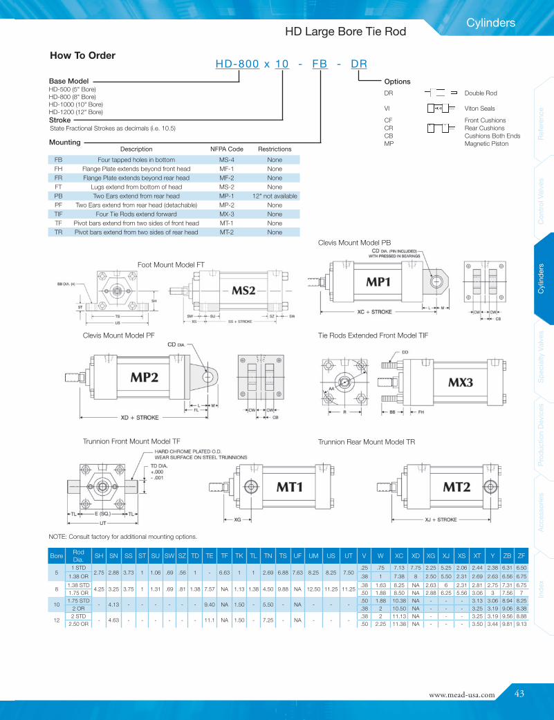
www.mead-usa.com #43
Inde
xAc
cess
ories
Prod
uctio
nDe
vices
Spec
ialty
Valve
sCy
linde
rsCo
ntrolV
alves
Referenc
e
Cylinders
OptionsDR Double Rod
VI Viton Seals
CF Front CushionsCR Rear CushionsCB Cushions Both EndsMP Magnetic Piston
BoreRodDia.
SH SN SS ST SU SW SZ TD TE TF TK TL TN TS UF UM US UT V W XC XD XG XJ XS XT Y ZB ZF
51 STD
2.75 2.88 3.73 1 1.06 .69 .56 1 - 6.63 1 1 2.69 6.88 7.63 8.25 8.25 7.50.25 .75 7.13 7.75 2.25 5.25 2.06 2.44 2.38 6.31 6.50
1.38 OR .38 1 7.38 8 2.50 5.50 2.31 2.69 2.63 6.56 6.75
81.38 STD
4.25 3.25 3.75 1 1.31 .69 .81 1.38 7.57 NA 1.13 1.38 4.50 9.88 NA 12.50 11.25 11.25.38 1.63 8.25 NA 2.63 6 2.31 2.81 2.75 7.31 6.75
1.75 OR .50 1.88 8.50 NA 2.88 6.25 5.56 3.06 3 7.56 7
101.75 STD
- 4.13 - - - - - - 9.40 NA 1.50 - 5.50 - NA - - -.50 1.88 10.38 NA - - - 3.13 3.06 8.94 8.25
2 OR .38 2 10.50 NA - - - 3.25 3.19 9.06 8.38
122 STD
- 4.63 - - - - - - 11.1 NA 1.50 - 7.25 - NA - - -.38 2 11.13 NA - - - 3.25 3.19 9.56 8.88
2.50 OR .50 2.25 11.38 NA - - - 3.50 3.44 9.81 9.13
How To OrderHD-800 x 10 - FB - DR
State Fractional Strokes as decimals (i.e. 10.5)
Foot Mount Model FT
Clevis Mount Model PF
Trunnion Front Mount Model TF Trunnion Rear Mount Model TR
Tie Rods Extended Front Model TIF
Clevis Mount Model PB
NOTE: Consult factory for additional mounting options.
Base Model
Stroke
MountingDescription NFPA Code Restrictions
FB Four tapped holes in bottom MS-4 NoneFH Flange Plate extends beyond front head MF-1 NoneFR Flange Plate extends beyond rear head MF-2 NoneFT Lugs extend from bottom of head MS-2 NonePB Two Ears extend from rear head MP-1 12" not availablePF Two Ears extend from rear head (detachable) MP-2 NoneTIF Four Tie Rods extend forward MX-3 NoneTF Pivot bars extend from two sides of front head MT-1 NoneTR Pivot bars extend from two sides of rear head MT-2 None
HD-500 (5" Bore)HD-800 (8" Bore)HD-1000 (10" Bore)HD-1200 (12" Bore)
HD Large Bore Tie Rod

44
Cylinders
ReferenceControlValves
CylindersSpecialtyValves
ProductionDevices
AccessoriesIndex
ReferenceControlValves
CylindersSpecialtyValves
ProductionDevices
AccessoriesIndex
During the cylinder break-in period, moleculesfrom the unique graphite-filled Teflon® piston sealbecame embedded in the pores of the hard coatedaluminum cylinder tube. This forms a long-lasting,super-smooth, self-lubricated surface.
Non-Lube
Rubber bumpers are built into each cylinder head toeliminate the metallic “clank” that occurs at strokecompletion.
Built-In Bumpers Absorb Impact
Technical Specifications
Pressure: 150 PSI Air, 250 PSI HydraulicBore Sizes: 1-1/8", 1-1/2", 2", 2-1/2" and 3"
Body: Hard Coated AluminumRod Bearing: Oil Impregnated Porous Bronze
Temperature Range: -40° F to 250° F (-40° C to 121° C) (to 400° F [204° C]on request)
Flush Bottom (FB) Pivot Bracket (PB)
Trunnion Rear (TR)Trunnion Front (TF)
Flush Front (FF)1-1/2", 2", 2-1/2" & 3" bores only
Flush Rear (FR)1-1/8" bore only
Flush Rear (FR)1-1/2", 2", 2-1/2" & 3" bores only
Pivot Extended (PE)1-1/8", 1-1/2" & 2" bores only
Threaded Nose (NS)Std. on all 1-1/8" bore mounts1-1/8", 1-1/2" & 2" bores only
C-112 PB
C-150 NS
Teflon Seals Create Smooth Breakaway
Centaur’s unique Teflon® piston seal eliminates the forward lurch thatoccurs when rubber seals breakaway from the cylinder tube surface.Rod motion remains smooth throughout the stroke.
Model C-112 C-150 C-200 C-250 C-300Sinking N/A CS-6100N-150 CS-6100N-200 CS-6100N-250 CS-6100N-300
Sourcing N/A CS-6100P-150 CS-6100P-200 CS-6100P-250 CS-6100P-300Reed N/A CS-6100R-150 CS-6100R-200 CS-6100R-250 CS-6100R-300
Solid State and Reed switches can senserod position anywhere within the stroke. Astainless steel clamp facilitates mountingat any location along the cylinder tube.Switches may be used singly or in multiplesand positioned at any point around thecylinder tube. The cylinder must have amagnetic piston. For technical information,see page 29.
Proximity Switches
Rod couplers simplify cylinder alignmentproblems by compensating for 2° angularerror and 1/16" lateral misalignment onboth extension and retraction strokes.
See page 26 for complete listing of Mead’s self-aligning rod couplers.
Self Aligning Rod Couplers
Model C-112 C-150 C-200 C-250 C-300
Rod Coupler DMA-312 DMA-500 DMA-625 DMA-750 DMA-1000
Economical & Repairable
Mead Centaur cylinders are built to match tie-rod performance, but areup to 45% less expensive and offer lubrication-free service. Centaurcylinders are not permanently crimped like most other round cylinders,so they can be disassembled for maintenance.
Low Cost Mounting
The flush bottom cylinder mounts directly onto a base plate with onlytwo bolts... no need for mounting brackets or other hardware. The pivotbracket is built-in for easy pivoting at the inlet axis. The bracket pivotswithin the cylinder length to save space and to eliminate one entirebracket that would be needed to mount other cylinders.
Because Centaur’s trunnions serve both as mounts and as assemblyelements, they cost less than any other trunnion mount on themarket.
Centaur
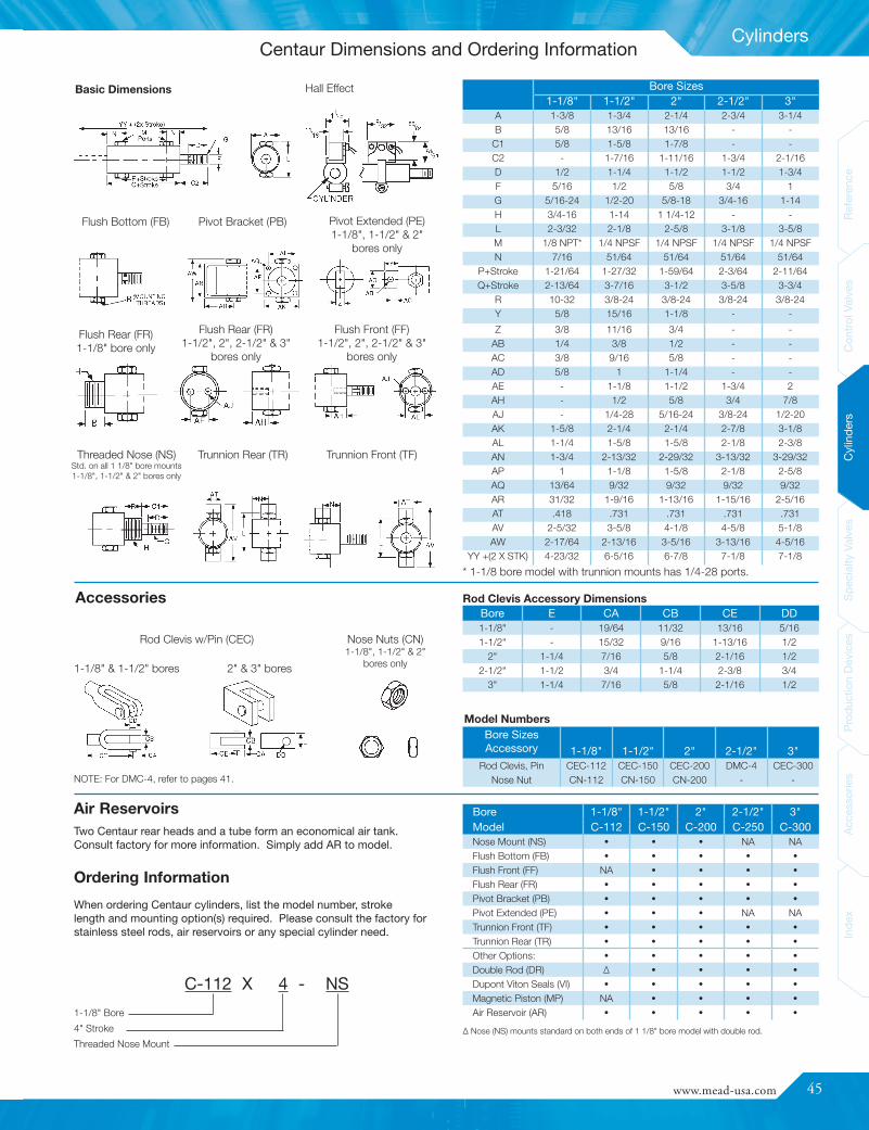
www.mead-usa.com #45
Inde
xAc
cess
ories
Prod
uctio
nDe
vices
Spec
ialty
Valve
sCy
linde
rsCo
ntrolV
alves
Referenc
e
Cylinders
Bore Sizes1-1/8" 1-1/2" 2" 2-1/2" 3"
A 1-3/8 1-3/4 2-1/4 2-3/4 3-1/4B 5/8 13/16 13/16 - -
C1 5/8 1-5/8 1-7/8 - -C2 - 1-7/16 1-11/16 1-3/4 2-1/16D 1/2 1-1/4 1-1/2 1-1/2 1-3/4F 5/16 1/2 5/8 3/4 1G 5/16-24 1/2-20 5/8-18 3/4-16 1-14H 3/4-16 1-14 1 1/4-12 - -L 2-3/32 2-1/8 2-5/8 3-1/8 3-5/8M 1/8 NPT* 1/4 NPSF 1/4 NPSF 1/4 NPSF 1/4 NPSFN 7/16 51/64 51/64 51/64 51/64
P+Stroke 1-21/64 1-27/32 1-59/64 2-3/64 2-11/64Q+Stroke 2-13/64 3-7/16 3-1/2 3-5/8 3-3/4
R 10-32 3/8-24 3/8-24 3/8-24 3/8-24Y 5/8 15/16 1-1/8 - -
Z 3/8 11/16 3/4 - -AB 1/4 3/8 1/2 - -AC 3/8 9/16 5/8 - -AD 5/8 1 1-1/4 - -AE - 1-1/8 1-1/2 1-3/4 2AH - 1/2 5/8 3/4 7/8AJ - 1/4-28 5/16-24 3/8-24 1/2-20AK 1-5/8 2-1/4 2-1/4 2-7/8 3-1/8AL 1-1/4 1-5/8 1-5/8 2-1/8 2-3/8AN 1-3/4 2-13/32 2-29/32 3-13/32 3-29/32AP 1 1-1/8 1-5/8 2-1/8 2-5/8AQ 13/64 9/32 9/32 9/32 9/32AR 31/32 1-9/16 1-13/16 1-15/16 2-5/16AT .418 .731 .731 .731 .731AV 2-5/32 3-5/8 4-1/8 4-5/8 5-1/8AW 2-17/64 2-13/16 3-5/16 3-13/16 4-5/16
YY +(2 X STK) 4-23/32 6-5/16 6-7/8 7-1/8 7-1/8
Bore SizesAccessory 1-1/8" 1-1/2" 2" 2-1/2" 3"
Rod Clevis, Pin CEC-112 CEC-150 CEC-200 DMC-4 CEC-300Nose Nut CN-112 CN-150 CN-200 - -
Bore E CA CB CE DD1-1/8" - 19/64 11/32 13/16 5/161-1/2" - 15/32 9/16 1-13/16 1/2
2" 1-1/4 7/16 5/8 2-1/16 1/22-1/2" 1-1/2 3/4 1-1/4 2-3/8 3/4
3" 1-1/4 7/16 5/8 2-1/16 1/2
Bore 1-1/8" 1-1/2" 2" 2-1/2" 3"Model C-112 C-150 C-200 C-250 C-300Nose Mount (NS) • • • NA NAFlush Bottom (FB) • • • • •Flush Front (FF) NA • • • •Flush Rear (FR) • • • • •Pivot Bracket (PB) • • • • •Pivot Extended (PE) • • • NA NATrunnion Front (TF) • • • • •Trunnion Rear (TR) • • • • •Other Options: • • • • •Double Rod (DR) Δ • • • •Dupont Viton Seals (VI) • • • • •Magnetic Piston (MP) NA • • • •Air Reservoir (AR) • • • • •
Basic Dimensions Hall Effect
Flush Front (FF)1-1/2", 2", 2-1/2" & 3"
bores only
Flush Rear (FR)1-1/8" bore only
Flush Rear (FR)1-1/2", 2", 2-1/2" & 3"
bores only
Flush Bottom (FB) Pivot Bracket (PB) Pivot Extended (PE)1-1/8", 1-1/2" & 2"
bores only
Rod Clevis w/Pin (CEC) Nose Nuts (CN)1-1/8", 1-1/2" & 2"
bores only
Accessories
Model Numbers
C-112 X 4 - NS
Trunnion Rear (TR)Threaded Nose (NS)Std. on all 1 1/8" bore mounts1-1/8", 1-1/2" & 2" bores only
Trunnion Front (TF)
1-1/8" & 1-1/2" bores 2" & 3" bores
Air Reservoirs
Ordering Information
When ordering Centaur cylinders, list the model number, strokelength and mounting option(s) required. Please consult the factory forstainless steel rods, air reservoirs or any special cylinder need.
Δ Nose (NS) mounts standard on both ends of 1 1/8" bore model with double rod.
* 1-1/8 bore model with trunnion mounts has 1/4-28 ports.
Rod Clevis Accessory Dimensions
1-1/8" Bore4" StrokeThreaded Nose Mount
Two Centaur rear heads and a tube form an economical air tank.Consult factory for more information. Simply add AR to model.
NOTE: For DMC-4, refer to pages 41.
Centaur Dimensions and Ordering Information

46
Cylinders
ReferenceControlValves
CylindersSpecialtyValves
ProductionDevices
AccessoriesIndex
ReferenceControlValves
CylindersSpecialtyValves
ProductionDevices
AccessoriesIndex
ModelNumber
Switch Type Switching LogicOperating
VoltageSwitchingCurrent
Switching Power Switching DropMagneticSensitivity
CS-7500R
Reed SwitchNormally
Open SPST5~20 VDC/
VAC 50/60Hz1 Amp. Max. 30 Watts Max. 3.5 V Max. 85 GaussCS-6100R
CS-6200RCS-7500P
Solid State(MR) Sensor
NormallyOpen
5~28 VDC 1 Amp. Max. 24 Watts Max.1.5 V Max.(0.5 Amp)
85 Gauss
CS-6100PCS-6200PCS-7500NCS-6100NCS-6200N
Connection Diagrams
Solid State: Sinking (NPN) OutputReed Switch
Brown
Blue
Load
Switch
Brown
Load
Solid State: Sourcing (PNP) Output
Brown
Black (Output)
Blue
Sw
itch
+~
-~
Sw
itch
+~
-~
Sw
itch
+~
-~
Load
Black (Output)
Blue
Load
Switch Compatible with
CS-6100 Centaur Round Body Cylinders
CS-6200 DM1 and HD1 Tie Rod Cylinders
CS-7500 DM2 Extruded Body Cylinders
Installation and OperationProximity switches provide contactless switching capabilitiesand allow you to sense cylinder rod position practicallyanywhere within the stroke. Switches are easily mounted onany point along the cylinder body. The switch will provide anelectrical signal when subjected to the magnetic field createdby a cylinder piston that is specially fitted with a captivatedmagnet.
Load
Proximity Switches (Reed/Solid State)
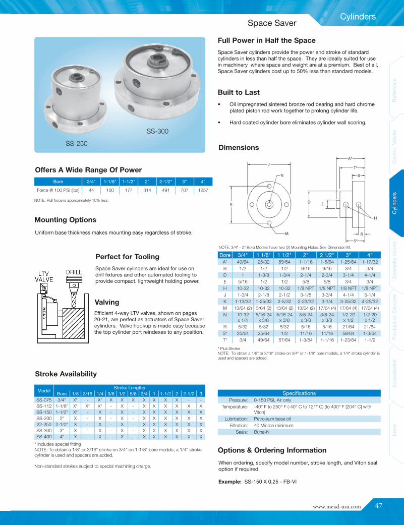
www.mead-usa.com #47
Inde
xAc
cess
ories
Prod
uctio
nDe
vices
Spec
ialty
Valve
sCy
linde
rsCo
ntrolV
alves
Referenc
e
Cylinders
Bore 3/4" 1 1/8" 1 1/2" 2" 2 1/2" 3" 4"A* 49/64 25/32 59/64 1-1/16 1-5/64 1-25/64 1-17/32B 1/2 1/2 1/2 9/16 9/16 3/4 3/4D 1 1-3/8 1-3/4 2-1/4 2-3/4 3-1/4 4-1/4E 5/16 1/2 1/2 5/8 5/8 3/4 3/4H 10-32 10-32 10-32 1/8 NPT 1/8 NPT 1/8 NPT 1/8 NPTJ 1-3/4 2-1/8 2-1/2 3-1/8 3-3/4 4-1/4 5-1/4K 1-13/32 1-25/32 2-5/32 2-23/32 3-1/4 3-25/32 4-25/32M 13/64 (2) 3/64 (2) 13/64 (2) 13/64 (2) 17/64 (4) 17/64 (4) 17/64 (4)N 10-32
x 1/45/16-24
x 3/85/16-24
x 3/83/8-24x 3/8
3/8-24x 3/8
1/2-20x 1/2
1/2-20x 1/2
R 5/32 5/32 5/32 5/16 5/16 21/64 21/64S* 25/64 25/64 1/2 11/16 11/16 59/64 1-3/64T* 3/4 49/64 57/64 1-3/64 1-1/16 1-23/64 1-1/2
SpecificationsPressure: 0-150 PSI, Air only
Temperature: -40° F to 250° F (-40° C to 121° C) (to 400° F [204° C] withViton)
Lubrication: Petroleum base oilFiltration: 40 Micron minimum
Seals: Buna-N
ModelStroke Lengths
Bore 1/8 3/16 1/4 3/8 1/2 5/8 3/4 1 1-1/2 2 2-1/2 3SS-075 3/4" X* - X* X X X X X X X - -SS-112 1-1/8" X* X* X* - X - X X X X X XSS-150 1-1/2" X* - X - X - X X X X X XSS-200 2" X - X - X - X X X X X X22-250 2-1/2" X - X - X - X X X X X XSS-300 3" X - X - X - X X X X X XSS-400 4" X - X - X - X X X X X X
Uniform base thickness makes mounting easy regardless of stroke.
When ordering, specify model number, stroke length, and Viton sealoption if required.
Example: SS-150 X 0.25 - FB-VI
Dimensions
Offers A Wide Range Of Power
SS-300
SS-250
Stroke Availability
NOTE: 3/4" - 2" Bore Models have two (2) Mounting Holes. See Dimension M.
Full Power in Half the Space
Built to Last
Mounting Options
Perfect for Tooling
ValvingEfficient 4-way LTV valves, shown on pages20-21, are perfect as actuators of Space Savercylinders. Valve hookup is made easy becausethe top cylinder port reindexes to any position.
Space Saver cylinders are ideal for use ondrill fixtures and other automated tooling toprovide compact, lightweight holding power.
Options & Ordering Information
Bore 3/4" 1-1/8" 1-1/2" 2" 2-1/2" 3" 4"
Force @ 100 PSI (lbs) 44 100 177 314 491 707 1257
NOTE: Pull force is approximately 10% less.
* Includes special fittingNOTE: To obtain a 1/8" or 3/16" stroke on 3/4" on 1-1/8" bore models, a 1/4" strokecylinder is used and spacers are added.
Non-standard strokes subject to special machining charge.
* Plus StrokeNOTE: To obtain a 1/8" or 3/16" stroke on 3/4" or 1-1/8" bore models, a 1/4" stroke cylinder isused and spacers are added.
Space Saver cylinders provide the power and stroke of standardcylinders in less than half the space. They are ideally suited for usein machinery where space and weight are at a premium. Best of all,Space Saver cylinders cost up to 50% less than standard models.
• Oil impregnated sintered bronze rod bearing and hard chromeplated piston rod work together to prolong cylinder life.
• Hard coated cylinder bore eliminates cylinder wall scoring.
Space Saver

48
Cylinders
ReferenceControlValves
CylindersSpecialtyValves
ProductionDevices
AccessoriesIndex
ReferenceControlValves
CylindersSpecialtyValves
ProductionDevices
AccessoriesIndex
The MA-250 (1/4" Bore) single acting is only available in 1/4" stroke lengths. The MA-250 double actingis available in 1/4", 1/2" and 1" stroke lengths. The MA-375 (3/8" Bore) and MA-500 (1/2" Bore) single
acting is available in 1/4" and 1/2"; the double acting version is available in 1/4", 1/2", 1", 1 1/2" and 2" stroke lengths. By adding a spacer, allmodels are also available in fractional stroke lengths for no additional charge. (Dimensionally the cylinder will be the same as the next closest sizeup.) If other strokes are required, contact Mead to quote a custom stroke length.
BorePMB 250
1/4"PMB 375
3/8"PMB 500
1/2"Width 0.503 0.626 0.75Height 0.879 0.876 0.94Depth 0.314 0.314 0.38
Hole (2) 0.14 0.139 0.136
MA - 500 x 1.00 DA - R B (*** )
PMB-500 PMB-375 PMB-250
Mounting Blocks
MA Series - Mini Adjustable Location Cylinders
Stroke Length Availability - MA Series
FamilyMA = Mini AdjustableMF = Mini Flat
Bore250 = 1/4" Bore375 = 3/8" Bore500 = 1/2" Bore
Stroke (in inches)See “Stroke Length Availability...” for particular series
TypeDA = Double ActingSR = Spring ReturnSE = Spring Extended
OptionsV = Viton SealsNR = Non-Rotating (Hex Rod) (MA Series only)
Front PortO = None (Spring Return)S = Side Tapped (10-32)B = 6-32 Barb (for 1/16" ID Hose)
Rear PortO = None (Spring Extend)R = Rear Tapped (10-32)S = Side Tapped (10-32)*B = 6-32 Barb (for 1/16" ID Hose)
* Special Order (non-stock; contact factory)
10-32 TAP
6-32 Barbs(for use with 1/16" ID Hose)Spring Extend Only
Bore A=Stroke+ B C D E F I J K M N1/4" 0.81 .15 .62 3/8-32 .14 6-32 .31 .06 .62 .20 .103/8" 1.00 .18 .75 1/2-32 .17 8-32 .31 .21 .75 .37 .181/2" 1.06 .18 .87 5/8-32 .25 1/4-28 .31 .21 .87 .37 -
These threaded body cylinders install quickly and easily without special mounting devices. Either drill ahole, insert your cylinder, and position with the pair of jam nuts or tap a hole and lock into position witha single jam nut. The MA-Series cylinders are electroless nickel plated for excellent corrosion resistanceand a gleaming appearance.
Non-rotating: This option is available on 3/8" and 1/2" bore, single-acting, spring return cylinders.
Ordering Miniature Cylinders:
Basic Cylinder Side and Rear Tapped
MA Cylinder Dimensions
AccessoriesFitting: 10-32 to 1/16" ID Hose ..........................PMHFFitting: 6-32 Barb to 1/16" ID Hose ....................PMBFHex Nut for 1/4" Bore Cylinder...........................PMH-250Hex Nut for 3/8" Bore Cylinder...........................PMH-375Hex Nut for 1/2" Bore Cylinder...........................PMH-5001/16" ID Tube Clear Polyurethane (50 ft.) ...........11NAT
Miniature Air Cylinders
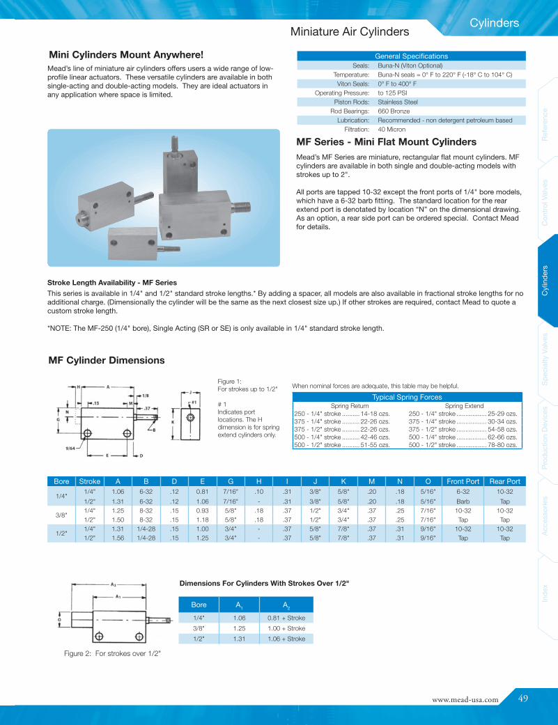
www.mead-usa.com #49
Inde
xAc
cess
ories
Prod
uctio
nDe
vices
Spec
ialty
Valve
sCy
linde
rsCo
ntrolV
alves
Referenc
e
Cylinders
Mead’s line of miniature air cylinders offers users a wide range of low-profile linear actuators. These versatile cylinders are available in bothsingle-acting and double-acting models. They are ideal actuators inany application where space is limited.
Bore A1 A2
1/4" 1.06 0.81 + Stroke
3/8" 1.25 1.00 + Stroke
1/2" 1.31 1.06 + Stroke
Bore Stroke A B D E G H I J K M N O Front Port Rear Port
1/4"1/4" 1.06 6-32 .12 0.81 7/16" .10 .31 3/8" 5/8" .20 .18 5/16" 6-32 10-32
1/2" 1.31 6-32 .12 1.06 7/16" - .31 3/8" 5/8" .20 .18 5/16" Barb Tap
3/8"1/4" 1.25 8-32 .15 0.93 5/8" .18 .37 1/2" 3/4" .37 .25 7/16" 10-32 10-321/2" 1.50 8-32 .15 1.18 5/8" .18 .37 1/2" 3/4" .37 .25 7/16" Tap Tap
1/2"1/4" 1.31 1/4-28 .15 1.00 3/4" - .37 5/8" 7/8" .37 .31 9/16" 10-32 10-321/2" 1.56 1/4-28 .15 1.25 3/4" - .37 5/8" 7/8" .37 .31 9/16" Tap Tap
Typical Spring ForcesSpring Return Spring Extend
250 - 1/4" stroke .......... 14-18 ozs. 250 - 1/4" stroke ................. 25-29 ozs.375 - 1/4" stroke .......... 22-26 ozs. 375 - 1/4" stroke ................. 30-34 ozs.375 - 1/2" stroke .......... 22-26 ozs. 375 - 1/2" stroke ................. 54-58 ozs.500 - 1/4" stroke .......... 42-46 ozs. 500 - 1/4" stroke ................. 62-66 ozs.500 - 1/2" stroke .......... 51-55 ozs. 500 - 1/2" stroke ................. 78-80 ozs.
General SpecificationsSeals: Buna-N (Viton Optional)
Temperature: Buna-N seals = 0° F to 220° F (-18° C to 104° C)Viton Seals: 0° F to 400° F
Operating Pressure: to 125 PSIPiston Rods: Stainless Steel
Rod Bearings: 660 BronzeLubrication: Recommended - non detergent petroleum based
Filtration: 40 Micron
Figure 2: For strokes over 1/2"
MF Cylinder Dimensions
Dimensions For Cylinders With Strokes Over 1/2"
Mini Cylinders Mount Anywhere!
MF Series - Mini Flat Mount Cylinders
When nominal forces are adequate, this table may be helpful.Figure 1:For strokes up to 1/2"
# 1Indicates portlocations. The Hdimension is for springextend cylinders only.
Stroke Length Availability - MF SeriesThis series is available in 1/4" and 1/2" standard stroke lengths.* By adding a spacer, all models are also available in fractional stroke lengths for noadditional charge. (Dimensionally the cylinder will be the same as the next closest size up.) If other strokes are required, contact Mead to quote acustom stroke length.
*NOTE: The MF-250 (1/4" bore), Single Acting (SR or SE) is only available in 1/4" standard stroke length.
Mead’s MF Series are miniature, rectangular flat mount cylinders. MFcylinders are available in both single and double-acting models withstrokes up to 2".
All ports are tapped 10-32 except the front ports of 1/4" bore models,which have a 6-32 barb fitting. The standard location for the rearextend port is denotated by location “N” on the dimensional drawing.As an option, a rear side port can be ordered special. Contact Meadfor details.
Miniature Air Cylinders
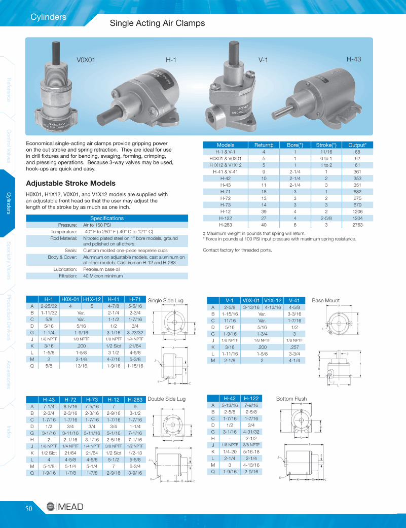
50
Cylinders
ReferenceControlValves
CylindersSpecialtyValves
ProductionDevices
AccessoriesIndex
ReferenceControlValves
CylindersSpecialtyValves
ProductionDevices
AccessoriesIndex
Models Return‡ Bore(") Stroke(") Output*H-1 & V-1 4 1 11/16 68
H0X01 & V0X01 5 1 0 to 1 62H1X12 & V1X12 5 1 1 to 2 61
H-41 & V-41 9 2-1/4 1 361H-42 10 2-1/4 2 353H-43 11 2-1/4 3 351H-71 18 3 1 682H-72 13 3 2 675H-73 14 3 3 679H-12 39 4 2 1206H-122 27 4 2-5/8 1204H-283 40 6 3 2763
SpecificationsPressure: Air to 150 PSI
Temperature: -40° F to 250° F (-40° C to 121° C)Rod Material: Nitrotec plated steel on 1" bore models, ground
and polished on all others.Seals: Custom molded one-piece neoprene cups
Body & Cover: Aluminum on adjustable models, cast aluminum onall other models. Cast iron on H-12 and H-283.
Lubrication: Petroleum base oilFiltration: 40 Micron minimum
H-42 H-122A 5-13/16 7-9/16B 2-5/8 2-5/8C 1-7/16 1-7/16D 1/2 3/4G 3-1/16 4-31/32H - 2-1/2J 1/8 NPTF 3/8 NPTF
K 1/4-20 5/16-18L 2-1/4 2-1/4M 3 4-13/16Q 1-9/16 2-9/16
V-1 V0X-01 V1X-12 V-41A 2-5/8 3-13/16 4-13/16 4-5/8B 1-15/16 Var. 3-3/16C 11/16 Var. 1-7/16D 5/16 5/16 1/2G 1-9/16 1-3/4 3J 1/8 NPTF 1/8 NPTF 1/8 NPTF
K 3/16 .200 .257L 1-11/16 1-5/8 3-3/4M 2-1/8 2 4-1/4
H-1 H0X-01 H1X-12 H-41 H-71A 2-25/32 4 5 4-7/8 5-5/16B 1-11/32 Var. 2-1/4 2-3/4C 5/8 Var. 1-1/2 1-7/16D 5/16 5/16 1/2 3/4G 1-1/4 1-9/16 3-1/16 3-23/32J 1/8 NPTF 1/8 NPTF 1/8 NPTF 1/4 NPTF
K 3/16 .200 1/2 Slot 21/64L 1-5/8 1-5/8 3 1/2 4-5/8M 2 2-1/8 4-7/16 5-3/8Q 5/8 13/16 1-9/16 1-15/16
H-43 H-72 H-73 H-12 H-283A 7-1/4 6-5/16 7-5/16 7 9B 2-3/4 2-3/16 2-3/16 2-9/16 3-1/2C 1-7/16 1-7/16 1-7/16 1-7/16 1-7/16D 1/2 3/4 3/4 3/4 1-1/4G 3-1/16 3-11/16 3-11/16 5-1/16 7-1/16H 2 2-1/16 3-1/16 2-5/16 7-1/16J 1/8 NPTF 1/4 NPTF 1/4 NPTF 3/8 NPTF 1/2 NPTF
K 1/2 Slot 21/64 21/64 1/2 Slot 1/2-13L 4 4-5/8 4-5/8 5-1/2 5-5/8M 5-1/8 5-1/4 5-1/4 7 6-3/4Q 1-9/16 1-7/8 1-7/8 2-9/16 3-9/16
V0X01 H-1 V-1
Single Side Lug
Double Side Lug
Base Mount
Bottom Flush
H-43
Adjustable Stroke ModelsH0X01, H1X12, V0X01, and V1X12 models are supplied withan adjustable front head so that the user may adjust thelength of the stroke by as much as one inch.
Economical single-acting air clamps provide gripping poweron the out stroke and spring retraction. They are ideal for usein drill fixtures and for bending, swaging, forming, crimping,and pressing operations. Because 3-way valves may be used,hook-ups are quick and easy.
‡ Maximum weight in pounds that spring will return.* Force in pounds at 100 PSI input pressure with maximum spring resistance.
Contact factory for threaded ports.
Single Acting Air Clamps

www.mead-usa.com #51
Spec
ialty
Valve
sProd
uctio
nDe
vices
Acce
ssories
Inde
xCy
linde
rsCo
ntrolV
alves
Referenc
eInde
xAc
cess
ories
Prod
uctio
nDe
vices
Spec
ialty
Valve
sCy
linde
rsCo
ntrolV
alves
Referenc
e
Specialty Valves
ModelModel (withGang Lock) Port Size Cv A (in.) B (in.)
SLV-25 SLVG-25 1/4" NPT 0.94 2-9/16" 1-1/4"
SLV-37 SLVG-37 3/8" NPT 2.00 2-15/16" 1-7/16"
SLV-50 SLVG-50 1/2" NPT 3.18 3-11/32" 1-5/8"
SpecificationsTemperature Range: -50° F to 180° F (-46° C to 82° C)
Pressure Range: 0 to 150 PSIMaterial:
Body: Black Anodized AluminumSleeve: Gold Anodized Aluminum
Retaining Ring: SteelO-Rings: Buna-N
Lock: Solid Brass (Steel Shackle)
Dimensions
Ordering Information
Easy Glide Ball Handle Valves (MHL SERIES)
SLV-37
MHL-3/MHL-4
“Gang Lock” Option
OSHA Rule 29 CFR1910.147*To protect employees from the unexpected energization or release ofstored energy during repair, maintenance and associated activities,this standard requires potentially hazardous energy sources for certainequipment to be disabled and either be locked or labeled with a warningtag to prevent unauthorized start-up of these machines or equipment.
*Copies of the actual OSHA standard may be obtained from the U.S.Department of Labor, Occupational Safety and Health Administration,Office of Publications, Room N3101, Washington, D.C. 20210.
SLVs may be ordered with a gang lock adapter rather than the standardMead padlock. The adapter permits the use of one or multiple standardpadlocks. To order, add a “G” to the model (i.e. SLVG-50).
In the closed position, air from compressor side is restricted whileexhaust air bleeds to atmosphere, rendering downstream equipmentinoperable. Lockout is only possible in the closed position.
Put a Lock on Plant AccidentsIn the open position, air flows freely through the valve to downstreamequipment or tool.
Slide/Lockout ValveMead’s Slide/Lockout Valves (SLV) are designed to comply with OSHAStandard Rule 29 CFR1910.147. SLVs exhaust downstream air toatmosphere when the valve is in the closed position. This prohibitsthe unexpected cycling of equipment due to stored energy in the airline. These valves can only be locked in the closed position, renderingany downstream machinery or equipment completely inoperable. Thealuminum sleeve is anodized bright gold for easy identification.
Low Friction Motion
Warning: SLVs are not to be used for lockout of hydraulic fluid.
NOTE: Use part #LCK100 to order replacement lock and key set.Use part #2028002 to order replacement gang lock.
MHL valves provide either 3-waypilot control (MHL-3) or 4-waydirectional control (MHL-4). Tooperate MHL valves, simply movethe ball handle across the slot onthe valve body. The handle rotatesa precision-lapped disc to controlthe directional flow of air. Thehardcoat anodized aluminum discallows virtually effortless handlemotion. The handle will hold inany position. Air exhausts throughthe disc and out to atmosphere.
Base mount holes make mounting and removal quick and easy.Further, MHL valves are easy to disassemble. By simply removingthe ball handle and snap ring, any part worn by use can be found andreplaced.
Low Friction Motion
General SpecificationsFlow: 0.14 Cv
Ports: 1/8" NPTTemperature Range: -40° F to 250° F (-40° C to 121° C)
Lubrication: SAE 10Pressure Range: 0 to 150 PSI (Air Only)
Seals: Buna-N
Lockout and Easy-Glide Ball Handle Valves
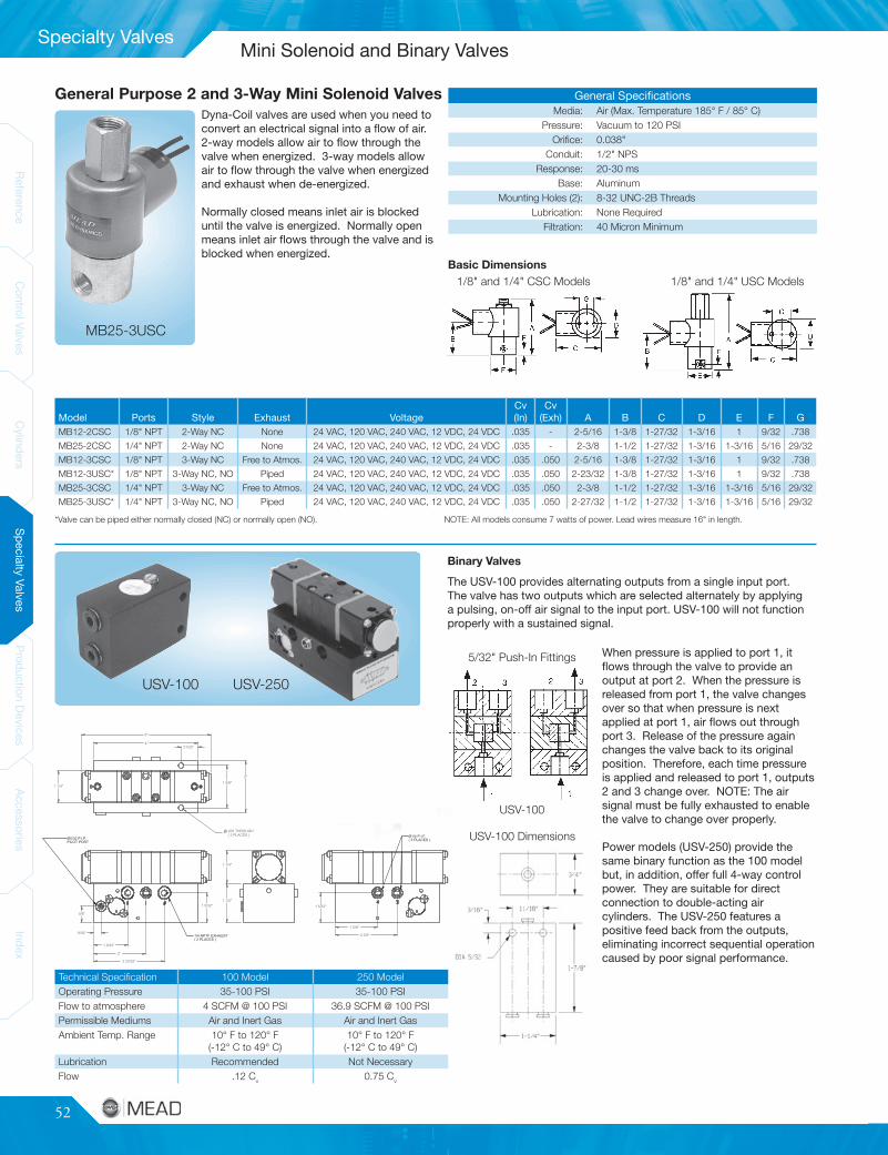
52
ReferenceControlValves
CylindersSpecialtyValves
ProductionDevices
AccessoriesIndex
ReferenceControlValves
CylindersSpecialtyValves
ProductionDevices
AccessoriesIndex
Specialty Valves
Dyna-Coil valves are used when you need toconvert an electrical signal into a flow of air.2-way models allow air to flow through thevalve when energized. 3-way models allowair to flow through the valve when energizedand exhaust when de-energized.
Normally closed means inlet air is blockeduntil the valve is energized. Normally openmeans inlet air flows through the valve and isblocked when energized.
Model Ports Style Exhaust VoltageCv(In)
Cv(Exh) A B C D E F G
MB12-2CSC 1/8" NPT 2-Way NC None 24 VAC, 120 VAC, 240 VAC, 12 VDC, 24 VDC .035 - 2-5/16 1-3/8 1-27/32 1-3/16 1 9/32 .738
MB25-2CSC 1/4" NPT 2-Way NC None 24 VAC, 120 VAC, 240 VAC, 12 VDC, 24 VDC .035 - 2-3/8 1-1/2 1-27/32 1-3/16 1-3/16 5/16 29/32
MB12-3CSC 1/8" NPT 3-Way NC Free to Atmos. 24 VAC, 120 VAC, 240 VAC, 12 VDC, 24 VDC .035 .050 2-5/16 1-3/8 1-27/32 1-3/16 1 9/32 .738
MB12-3USC* 1/8" NPT 3-Way NC, NO Piped 24 VAC, 120 VAC, 240 VAC, 12 VDC, 24 VDC .035 .050 2-23/32 1-3/8 1-27/32 1-3/16 1 9/32 .738
MB25-3CSC 1/4" NPT 3-Way NC Free to Atmos. 24 VAC, 120 VAC, 240 VAC, 12 VDC, 24 VDC .035 .050 2-3/8 1-1/2 1-27/32 1-3/16 1-3/16 5/16 29/32
MB25-3USC* 1/4" NPT 3-Way NC, NO Piped 24 VAC, 120 VAC, 240 VAC, 12 VDC, 24 VDC .035 .050 2-27/32 1-1/2 1-27/32 1-3/16 1-3/16 5/16 29/32
General SpecificationsMedia: Air (Max. Temperature 185° F / 85° C)
Pressure: Vacuum to 120 PSIOrifice: 0.038"
Conduit: 1/2" NPSResponse: 20-30 ms
Base: AluminumMounting Holes (2): 8-32 UNC-2B Threads
Lubrication: None RequiredFiltration: 40 Micron Minimum
Basic Dimensions1/8" and 1/4" CSC Models 1/8" and 1/4" USC Models
5/32" Push-In Fittings
USV-100 Dimensions
MB25-3USC
General Purpose 2 and 3-Way Mini Solenoid Valves
USV-100
*Valve can be piped either normally closed (NC) or normally open (NO). NOTE: All models consume 7 watts of power. Lead wires measure 16" in length.
Technical Specification 100 Model 250 ModelOperating Pressure 35-100 PSI 35-100 PSIFlow to atmosphere 4 SCFM @ 100 PSI 36.9 SCFM @ 100 PSIPermissible Mediums Air and Inert Gas Air and Inert GasAmbient Temp. Range 10° F to 120° F
(-12° C to 49° C)10° F to 120° F
(-12° C to 49° C)Lubrication Recommended Not NecessaryFlow .12 Cv 0.75 Cv
USV-100 USV-250
When pressure is applied to port 1, itflows through the valve to provide anoutput at port 2. When the pressure isreleased from port 1, the valve changesover so that when pressure is nextapplied at port 1, air flows out throughport 3. Release of the pressure againchanges the valve back to its originalposition. Therefore, each time pressureis applied and released to port 1, outputs2 and 3 change over. NOTE: The airsignal must be fully exhausted to enablethe valve to change over properly.
Power models (USV-250) provide thesame binary function as the 100 modelbut, in addition, offer full 4-way controlpower. They are suitable for directconnection to double-acting aircylinders. The USV-250 features apositive feed back from the outputs,eliminating incorrect sequential operationcaused by poor signal performance.
Binary ValvesThe USV-100 provides alternating outputs from a single input port.The valve has two outputs which are selected alternately by applyinga pulsing, on-off air signal to the input port. USV-100 will not functionproperly with a sustained signal.
Mini Solenoid and Binary Valves
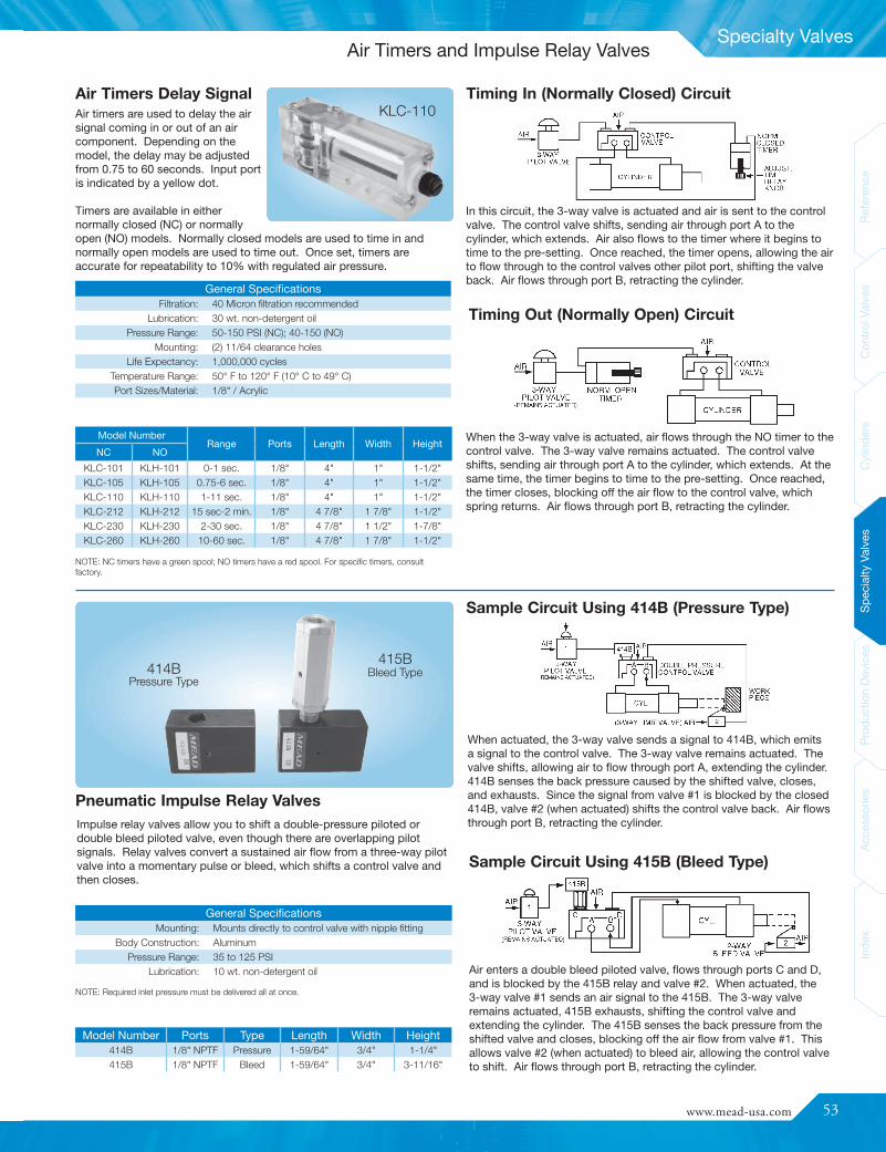
www.mead-usa.com #53
Spec
ialty
Valve
sProd
uctio
nDe
vices
Acce
ssories
Inde
xCy
linde
rsCo
ntrolV
alves
Referenc
eInde
xAc
cess
ories
Prod
uctio
nDe
vices
Spec
ialty
Valve
sCy
linde
rsCo
ntrolV
alves
Referenc
e
Specialty Valves
Model Number Ports Type Length Width Height414B 1/8" NPTF Pressure 1-59/64" 3/4" 1-1/4"415B 1/8" NPTF Bleed 1-59/64" 3/4" 3-11/16"
General SpecificationsFiltration: 40 Micron filtration recommended
Lubrication: 30 wt. non-detergent oilPressure Range: 50-150 PSI (NC); 40-150 (NO)
Mounting: (2) 11/64 clearance holesLife Expectancy: 1,000,000 cycles
Temperature Range: 50° F to 120° F (10° C to 49° C)Port Sizes/Material: 1/8" / Acrylic
Air timers are used to delay the airsignal coming in or out of an aircomponent. Depending on themodel, the delay may be adjustedfrom 0.75 to 60 seconds. Input portis indicated by a yellow dot.
Timers are available in eithernormally closed (NC) or normallyopen (NO) models. Normally closed models are used to time in andnormally open models are used to time out. Once set, timers areaccurate for repeatability to 10% with regulated air pressure.
Model NumberRange Ports Length Width Height
NC NO
KLC-101 KLH-101 0-1 sec. 1/8" 4" 1" 1-1/2"KLC-105 KLH-105 0.75-6 sec. 1/8" 4" 1" 1-1/2"KLC-110 KLH-110 1-11 sec. 1/8" 4" 1" 1-1/2"KLC-212 KLH-212 15 sec-2 min. 1/8" 4 7/8" 1 7/8" 1-1/2"KLC-230 KLH-230 2-30 sec. 1/8" 4 7/8" 1 1/2" 1-7/8"KLC-260 KLH-260 10-60 sec. 1/8" 4 7/8" 1 7/8" 1-1/2"
Impulse relay valves allow you to shift a double-pressure piloted ordouble bleed piloted valve, even though there are overlapping pilotsignals. Relay valves convert a sustained air flow from a three-way pilotvalve into a momentary pulse or bleed, which shifts a control valve andthen closes.
Sample Circuit Using 415B (Bleed Type)
When actuated, the 3-way valve sends a signal to 414B, which emitsa signal to the control valve. The 3-way valve remains actuated. Thevalve shifts, allowing air to flow through port A, extending the cylinder.414B senses the back pressure caused by the shifted valve, closes,and exhausts. Since the signal from valve #1 is blocked by the closed414B, valve #2 (when actuated) shifts the control valve back. Air flowsthrough port B, retracting the cylinder.
Air enters a double bleed piloted valve, flows through ports C and D,and is blocked by the 415B relay and valve #2. When actuated, the3-way valve #1 sends an air signal to the 415B. The 3-way valveremains actuated, 415B exhausts, shifting the control valve andextending the cylinder. The 415B senses the back pressure from theshifted valve and closes, blocking off the air flow from valve #1. Thisallows valve #2 (when actuated) to bleed air, allowing the control valveto shift. Air flows through port B, retracting the cylinder.
Timing In (Normally Closed) Circuit
In this circuit, the 3-way valve is actuated and air is sent to the controlvalve. The control valve shifts, sending air through port A to thecylinder, which extends. Air also flows to the timer where it begins totime to the pre-setting. Once reached, the timer opens, allowing the airto flow through to the control valves other pilot port, shifting the valveback. Air flows through port B, retracting the cylinder.
Timing Out (Normally Open) Circuit
When the 3-way valve is actuated, air flows through the NO timer to thecontrol valve. The 3-way valve remains actuated. The control valveshifts, sending air through port A to the cylinder, which extends. At thesame time, the timer begins to time to the pre-setting. Once reached,the timer closes, blocking off the air flow to the control valve, whichspring returns. Air flows through port B, retracting the cylinder.
Sample Circuit Using 414B (Pressure Type)
Pneumatic Impulse Relay Valves
Air Timers Delay Signal
NOTE: NC timers have a green spool; NO timers have a red spool. For specific timers, consultfactory.
General SpecificationsMounting: Mounts directly to control valve with nipple fitting
Body Construction: AluminumPressure Range: 35 to 125 PSI
Lubrication: 10 wt. non-detergent oil
NOTE: Required inlet pressure must be delivered all at once.
Pressure Type414B Bleed Type
415B
KLC-110
Air Timers and Impulse Relay Valves
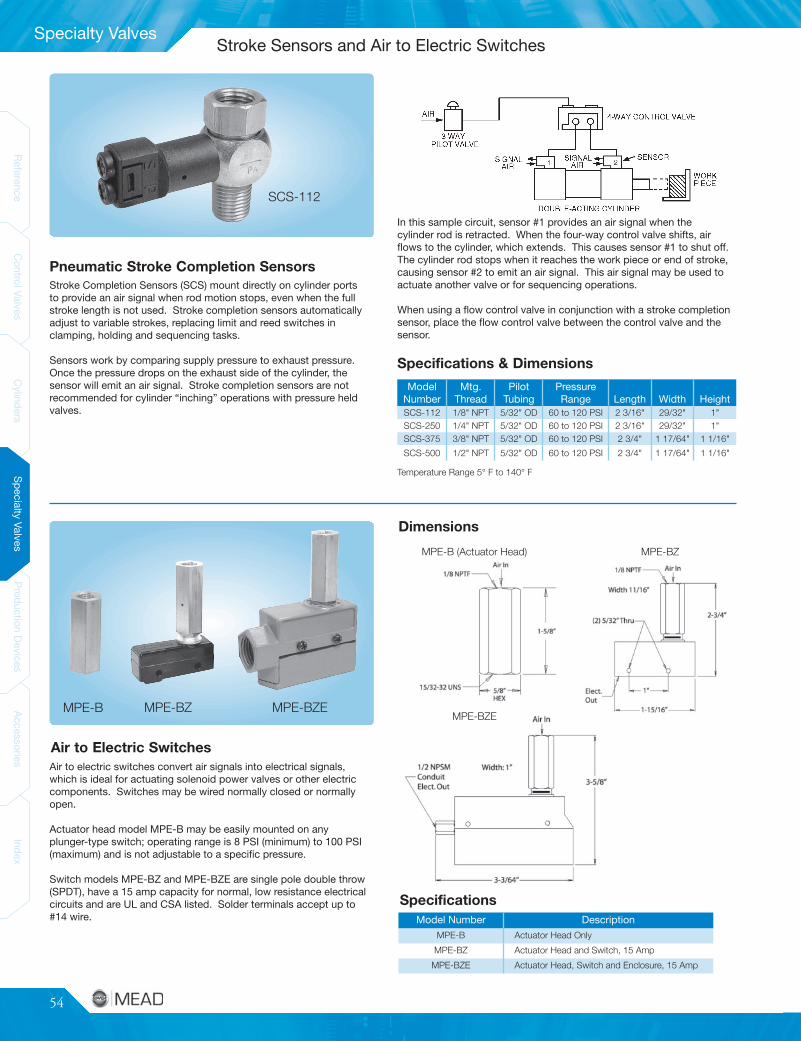
54
ReferenceControlValves
CylindersSpecialtyValves
ProductionDevices
AccessoriesIndex
ReferenceControlValves
CylindersSpecialtyValves
ProductionDevices
AccessoriesIndex
Specialty Valves
ModelNumber
Mtg.Thread
PilotTubing
PressureRange Length Width Height
SCS-112 1/8" NPT 5/32" OD 60 to 120 PSI 2 3/16" 29/32" 1"SCS-250 1/4" NPT 5/32" OD 60 to 120 PSI 2 3/16" 29/32" 1"SCS-375 3/8" NPT 5/32" OD 60 to 120 PSI 2 3/4" 1 17/64" 1 1/16"
SCS-500 1/2" NPT 5/32" OD 60 to 120 PSI 2 3/4" 1 17/64" 1 1/16"
Model Number DescriptionMPE-B Actuator Head Only
MPE-BZ Actuator Head and Switch, 15 Amp
MPE-BZE Actuator Head, Switch and Enclosure, 15 Amp
MPE-BZ MPE-BZE
Specifications
MPE-BZEMPE-B
Pneumatic Stroke Completion Sensors
Specifications & Dimensions
Air to Electric Switches
Dimensions
MPE-B (Actuator Head) MPE-BZ
Temperature Range 5° F to 140° F
Stroke Completion Sensors (SCS) mount directly on cylinder portsto provide an air signal when rod motion stops, even when the fullstroke length is not used. Stroke completion sensors automaticallyadjust to variable strokes, replacing limit and reed switches inclamping, holding and sequencing tasks.
Sensors work by comparing supply pressure to exhaust pressure.Once the pressure drops on the exhaust side of the cylinder, thesensor will emit an air signal. Stroke completion sensors are notrecommended for cylinder “inching” operations with pressure heldvalves.
SCS-112
Air to electric switches convert air signals into electrical signals,which is ideal for actuating solenoid power valves or other electriccomponents. Switches may be wired normally closed or normallyopen.
Actuator head model MPE-B may be easily mounted on anyplunger-type switch; operating range is 8 PSI (minimum) to 100 PSI(maximum) and is not adjustable to a specific pressure.
Switch models MPE-BZ and MPE-BZE are single pole double throw(SPDT), have a 15 amp capacity for normal, low resistance electricalcircuits and are UL and CSA listed. Solder terminals accept up to#14 wire.
In this sample circuit, sensor #1 provides an air signal when thecylinder rod is retracted. When the four-way control valve shifts, airflows to the cylinder, which extends. This causes sensor #1 to shut off.The cylinder rod stops when it reaches the work piece or end of stroke,causing sensor #2 to emit an air signal. This air signal may be used toactuate another valve or for sequencing operations.
When using a flow control valve in conjunction with a stroke completionsensor, place the flow control valve between the control valve and thesensor.
Stroke Sensors and Air to Electric Switches
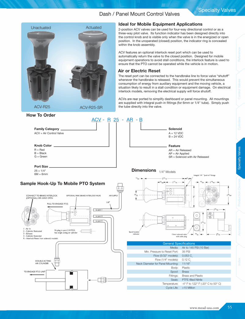
www.mead-usa.com #55
Spec
ialty
Valve
sProd
uctio
nDe
vices
Acce
ssories
Inde
xCy
linde
rsCo
ntrolV
alves
Referenc
eInde
xAc
cess
ories
Prod
uctio
nDe
vices
Spec
ialty
Valve
sCy
linde
rsCo
ntrolV
alves
Referenc
e
Specialty Valves
General SpecificationsMedia: Air to 145 PSI (10 Bar)
Min. Pressure to Reset Port: 35 PSIFlow (5/32" models): 0.053 Cv
Flow (1/4" models): 0.12 Cv
Neck Diameter for Panel Mounting: 11/16"Body: PlasticSpool: Brass
Fittings: Brass and PlasticSeals: PTFE-filled Nitrile
Temperature: -4° F to 122° F (-20° C to 50° C)Cycle Life: >15 Million
Dimensions
ACV-R25 ACV-R25-SR
ActuatedUnactuated
1/4" Models
Sample Hook-Up To Mobile PTO System
ACV - R 25 - AR - BHow To Order
Ideal for Mobile Equipment Applications2-position ACV valves can be used for four-way directional control or as athree-way pilot valve. Its function indicator has been designed directly intothe control knob and is visible only when the valve is in the energized or openposition. In the unoperated (closed) position, the indicator ring is concealedwithin the knob assembly.
ACV features an optional interlock reset port which can be used toautomatically return the valve to the closed position. Designed for mobileequipment operations to avoid stall conditions, the interlock feature is used toensure that the PTO cannot be operated while the vehicle is in motion.
The reset port can be connected to the handbrake line to force valve “shutoff”whenever the handbrake is released. This would prevent the simultaneousconsumption of energy from auxiliary equipment and the moving vehicle, asituation likely to result in a stall condition or equipment damage. On electricalinterlock models, removing the electrical supply will force shutoff.
ACVs are rear ported to simplify dashboard or panel mounting. All mountingsare supplied with integral push-in fittings (for 6mm or 1/4" tube). Simply pushthe tube directly into the valve.
Air or Electric Reset
Knob ColorR = RedB = BlackG = Green
Family CategoryACV = Air Control Valve
Port Size25 = 1/4"6M = 6mm
SolenoidA = 12 VDCB = 24 VDC
FeatureAR = Air ReleasedAP = Air AppliedSR = Solenoid with Air Released
Dash / Panel Mount Control Valves
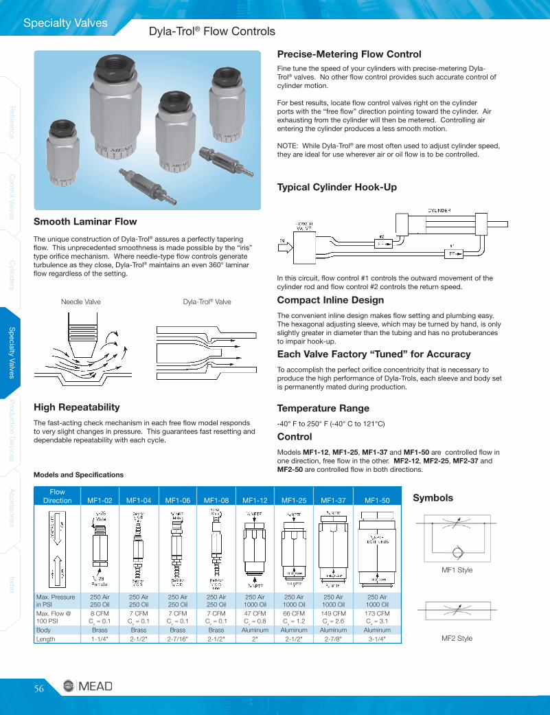
56
ReferenceControlValves
CylindersSpecialtyValves
ProductionDevices
AccessoriesIndex
ReferenceControlValves
CylindersSpecialtyValves
ProductionDevices
AccessoriesIndex
Specialty Valves
FlowDirection MF1-02 MF1-04 MF1-06 MF1-08 MF1-12 MF1-25 MF1-37 MF1-50
Max. Pressurein PSI
250 Air250 Oil
250 Air250 Oil
250 Air250 Oil
250 Air250 Oil
250 Air1000 Oil
250 Air1000 Oil
250 Air1000 Oil
250 Air1000 Oil
Max. Flow @100 PSI
8 CFMCv = 0.1
7 CFMCv = 0.1
7 CFMCv = 0.1
7 CFMCv = 0.1
47 CFMCv = 0.8
66 CFMCv = 1.2
149 CFMCv = 2.6
173 CFMCv = 3.1
Body Brass Brass Brass Brass Aluminum Aluminum Aluminum AluminumLength 1-1/4" 2-1/2" 2-7/16" 2-1/2" 2" 2-1/2" 2-7/8" 3-1/4"
Control
Models MF1-12, MF1-25, MF1-37 and MF1-50 are controlled flow inone direction, free flow in the other. MF2-12, MF2-25, MF2-37 andMF2-50 are controlled flow in both directions.
MF1 Style
MF2 Style
Smooth Laminar Flow
High Repeatability
Precise-Metering Flow ControlFine tune the speed of your cylinders with precise-metering Dyla-Trol® valves. No other flow control provides such accurate control ofcylinder motion.
For best results, locate flow control valves right on the cylinderports with the “free flow” direction pointing toward the cylinder. Airexhausting from the cylinder will then be metered. Controlling airentering the cylinder produces a less smooth motion.
NOTE: While Dyla-Trol® are most often used to adjust cylinder speed,they are ideal for use wherever air or oil flow is to be controlled.
Typical Cylinder Hook-Up
In this circuit, flow control #1 controls the outward movement of thecylinder rod and flow control #2 controls the return speed.
Compact Inline Design
The convenient inline design makes flow setting and plumbing easy.The hexagonal adjusting sleeve, which may be turned by hand, is onlyslightly greater in diameter than the tubing and has no protuberancesto impair hook-up.
Each Valve Factory “Tuned” for Accuracy
To accomplish the perfect orifice concentricity that is necessary toproduce the high performance of Dyla-Trols, each sleeve and body setis permanently mated during production.
Temperature Range
-40° F to 250° F (-40° C to 121°C)
Symbols
1/4 NPTF
The unique construction of Dyla-Trol® assures a perfectly taperingflow. This unprecedented smoothness is made possible by the “iris”type orifice mechanism. Where needle-type flow controls generateturbulence as they close, Dyla-Trol® maintains an even 360° laminarflow regardless of the setting.
Needle Valve Dyla-Trol® Valve
The fast-acting check mechanism in each free flow model respondsto very slight changes in pressure. This guarantees fast resetting anddependable repeatability with each cycle.
Models and Specifications
Dyla-Trol® Flow Controls
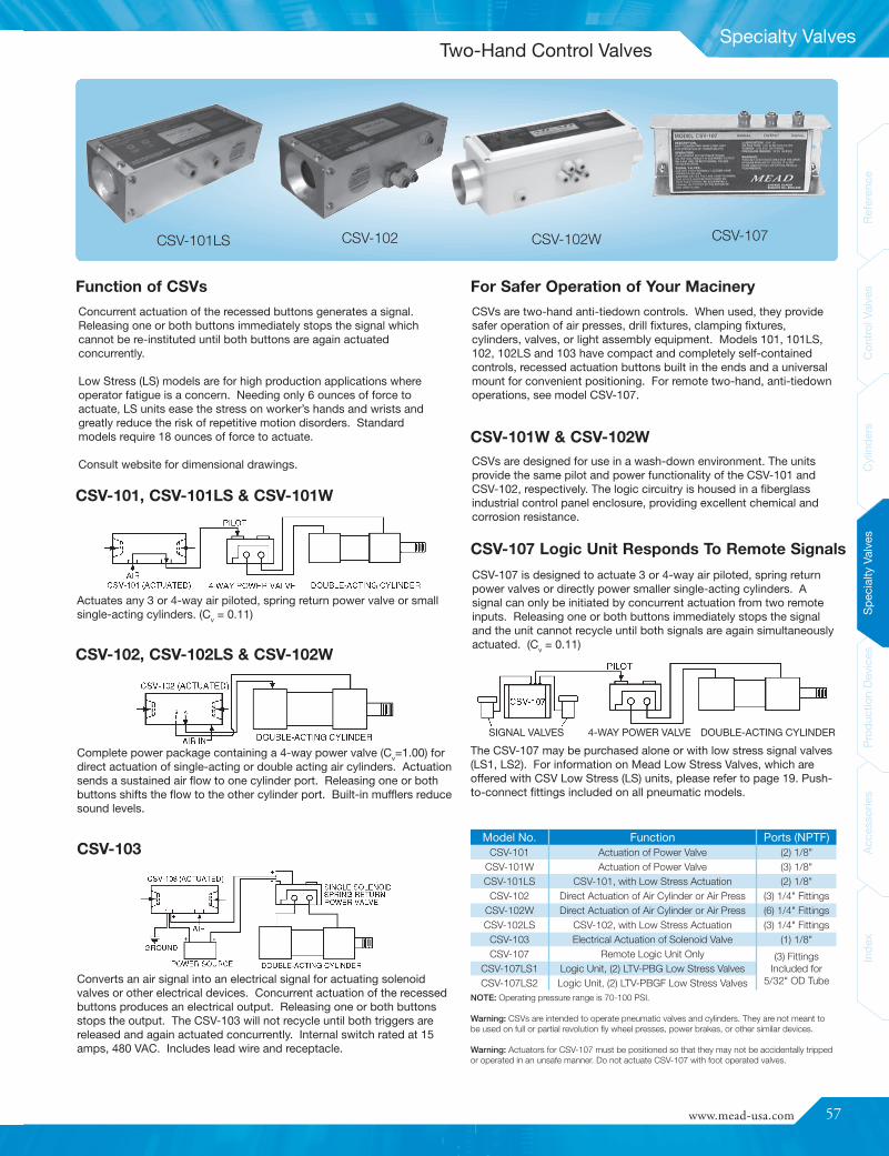
www.mead-usa.com #57
Spec
ialty
Valve
sProd
uctio
nDe
vices
Acce
ssories
Inde
xCy
linde
rsCo
ntrolV
alves
Referenc
eInde
xAc
cess
ories
Prod
uctio
nDe
vices
Spec
ialty
Valve
sCy
linde
rsCo
ntrolV
alves
Referenc
e
Specialty Valves
Model No. Function Ports (NPTF)CSV-101 Actuation of Power Valve (2) 1/8"
CSV-101W Actuation of Power Valve (3) 1/8"CSV-101LS CSV-101, with Low Stress Actuation (2) 1/8"
CSV-102 Direct Actuation of Air Cylinder or Air Press (3) 1/4" FittingsCSV-102W Direct Actuation of Air Cylinder or Air Press (6) 1/4" FittingsCSV-102LS CSV-102, with Low Stress Actuation (3) 1/4" Fittings
CSV-103 Electrical Actuation of Solenoid Valve (1) 1/8"CSV-107 Remote Logic Unit Only (3) Fittings
Included for5/32" OD Tube
CSV-107LS1 Logic Unit, (2) LTV-PBG Low Stress ValvesCSV-107LS2 Logic Unit, (2) LTV-PBGF Low Stress Valves
CSVs are two-hand anti-tiedown controls. When used, they providesafer operation of air presses, drill fixtures, clamping fixtures,cylinders, valves, or light assembly equipment. Models 101, 101LS,102, 102LS and 103 have compact and completely self-containedcontrols, recessed actuation buttons built in the ends and a universalmount for convenient positioning. For remote two-hand, anti-tiedownoperations, see model CSV-107.
CSVs are designed for use in a wash-down environment. The unitsprovide the same pilot and power functionality of the CSV-101 andCSV-102, respectively. The logic circuitry is housed in a fiberglassindustrial control panel enclosure, providing excellent chemical andcorrosion resistance.
Concurrent actuation of the recessed buttons generates a signal.Releasing one or both buttons immediately stops the signal whichcannot be re-instituted until both buttons are again actuatedconcurrently.
Low Stress (LS) models are for high production applications whereoperator fatigue is a concern. Needing only 6 ounces of force toactuate, LS units ease the stress on worker’s hands and wrists andgreatly reduce the risk of repetitive motion disorders. Standardmodels require 18 ounces of force to actuate.
Consult website for dimensional drawings.
CSV-107 is designed to actuate 3 or 4-way air piloted, spring returnpower valves or directly power smaller single-acting cylinders. Asignal can only be initiated by concurrent actuation from two remoteinputs. Releasing one or both buttons immediately stops the signaland the unit cannot recycle until both signals are again simultaneouslyactuated. (Cv = 0.11)
CSV-102 CSV-102W CSV-107CSV-101LS
Function of CSVs
CSV-101, CSV-101LS & CSV-101W
Actuates any 3 or 4-way air piloted, spring return power valve or smallsingle-acting cylinders. (Cv = 0.11)
CSV-102, CSV-102LS & CSV-102W
Complete power package containing a 4-way power valve (Cv=1.00) fordirect actuation of single-acting or double acting air cylinders. Actuationsends a sustained air flow to one cylinder port. Releasing one or bothbuttons shifts the flow to the other cylinder port. Built-in mufflers reducesound levels.
CSV-103
Converts an air signal into an electrical signal for actuating solenoidvalves or other electrical devices. Concurrent actuation of the recessedbuttons produces an electrical output. Releasing one or both buttonsstops the output. The CSV-103 will not recycle until both triggers arereleased and again actuated concurrently. Internal switch rated at 15amps, 480 VAC. Includes lead wire and receptacle.
For Safer Operation of Your Macinery
CSV-101W & CSV-102W
CSV-107 Logic Unit Responds To Remote Signals
SIGNAL VALVES 4-WAY POWER VALVE DOUBLE-ACTING CYLINDERThe CSV-107 may be purchased alone or with low stress signal valves(LS1, LS2). For information on Mead Low Stress Valves, which areoffered with CSV Low Stress (LS) units, please refer to page 19. Push-to-connect fittings included on all pneumatic models.
NOTE: Operating pressure range is 70-100 PSI.
Warning: CSVs are intended to operate pneumatic valves and cylinders. They are not meant tobe used on full or partial revolution fly wheel presses, power brakes, or other similar devices.
Warning: Actuators for CSV-107 must be positioned so that they may not be accidentally trippedor operated in an unsafe manner. Do not actuate CSV-107 with foot operated valves.
Two-Hand Control Valves

58
ReferenceControlValves
CylindersSpecialtyValves
ProductionDevices
AccessoriesIndex
ReferenceControlValves
CylindersSpecialtyValves
ProductionDevices
AccessoriesIndex
Production Devices
Description1/4 Ton
Arbor Press
3/4 TonColumnPress
3/4 TonArbor Press
1-3/4 TonArbor Press
Press Stand Only AP-42M CP-400M AP-400M AP-600M
Cylinder Mounted on Stand ** AP-42P CP-400P AP-400P AP-600P
Complete Press with Two HandControls (Not Piped)
- CP-400C AP-400C AP-600C
Double Rod Option (DR) NA • • •
Non-Rotating Option (NR) NA • • •
Specifications
Cylinder Bore (in.) 2-1/4 4 4 6
Thrust at 100 PSI (lbs.) 353 1257 1257 2827
Standard Stroke Length (in.) 2 (Spr. Ret.) 4* 2 1/2* 4*
Surface Table Width and Depth (in.) 3 x 3 6-7/8 x 8-3/4 5 x 5 8 x 8
To control the downward speed of double-acting presses,place a Mead Dyla-Trol valve (see page 56) in the bottomcylinder port so that incoming air flows freely and exhaustingair is metered. Model MF1-25 is suitable for the control of allpresses under most conditions.
Double-acting press cylinders may be ordered with thepiston rod extending from both ends. This minimizes roddeflection and make it possible to adjust stroke length.When a CP-400 is ordered with double rod, spacers aresupplied to facilitate adjustment.
Quick exhaust valves increase rod speed by allowingexhaust air to be dumped right at the cylinder instead ofpassing back through the directional valve. If speed is tobe increased in both directions on double-acting presses,use one QEV in each port. Use model QEV-3 with 1/4 ton
presses and model QEV-2B on 3/4 and 1-3/4 ton models. See page 63for more information regarding QEVs.
Models with a “C” suffix are supplied with a two handanti-tiedown unit. Recessed trigger buttons, locatedin each end of the compact unit, require the pressoperator to use both hands concurrently to operate thepress. Models CP-400C and AP-400C include the CSV-102, which has a built-in power valve. Model AP-600C
includes the CSV-101 and a 1/2" power valve (C5-3). All air logic. Noelectrical wiring. See page 57 for the two hand controls. See pages16-17 for the power valve.
Column provides infinitelyvariable daylight settings andpermits radial swing.
Heavy-duty cast iron frameis extremely rigid.
Welded steel plate frame. Cylindermount and table are milled toprovide precise rod alignment.
Versatile, light-duty press.Single-acting, spring return.
Air Presses Automate TasksEconomical air powered presses reduceproduction costs by automating crimping, heatsealing, bending, forming, pressing, swaging,riveting and burnishing operations. Easyhook-up. Just attach to your shop air supply. Nowiring, pumps, or motors needed.
Single-Acting Air PressesBesides the AP-42P shown on this page, Meadoffers two other single-acting alternatives. AP-122 combines a 4" bore single-acting cylinder(H-122) with the AP-400M press stand. AP-283combines a 6" bore cylinder (#6030403) withthe AP-600M press stand. A PL-600 cylinder-to-stand adapter plate is required for mounting thiscylinder on the stand. Full dimensional drawingsare given on page 60.
Press Options
Rod Speed Reduction
Two Hand Control Unit Press Speed Boost
Double Rod Option (DR)
See page 60 for Air Press dimensions.
NOTE: Standard column for Column Press is 14" long. Longer column (18" max.) is available upon request.* Additional stroke available to 4" on AP-400 and to 6" on AP-600. Consult factory.** Consult website for press hookups.
AP-42P CP-400P AP-400P AP-600P3/4 Ton Column Press1/4 Ton Arbor Press 3/4 Ton Arbor Press 1-3/4 Ton Arbor Press
Air Presses
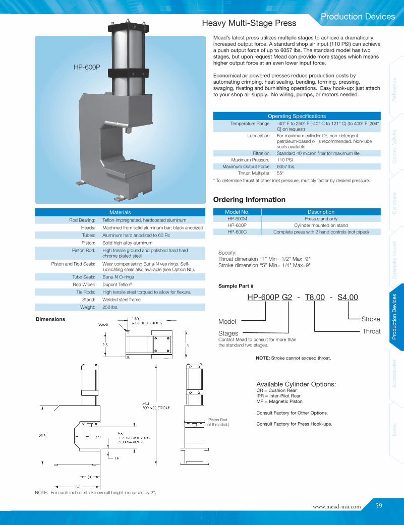
www.mead-usa.com #59
Spec
ialty
Valve
sProd
uctio
nDe
vices
Acce
ssories
Inde
xCy
linde
rsCo
ntrolV
alves
Referenc
eInde
xAc
cess
ories
Prod
uctio
nDe
vices
Spec
ialty
Valve
sCy
linde
rsCo
ntrolV
alves
Referenc
e
Production Devices
Model No. DescriptionHP-600M Press stand onlyHP-600P Cylinder mounted on standHP-600C Complete press with 2 hand controls (not piped)
MaterialsRod Bearing: Teflon-impregnated, hardcoated aluminum
Heads: Machined from solid aluminum bar; black anodized
Tubes: Aluminum hard anodized to 60 Rc
Piston: Solid high alloy aluminum
Piston Rod: High tensile ground and polished hard hardchrome plated steel
Piston and Rod Seals: Wear compensating Buna-N vee rings. Self-lubricating seals also available (see Option NL).
Tube Seals: Buna-N O-rings
Rod Wiper: Dupont Teflon®
Tie Rods: High tensile steel torqued to allow for flexure.
Stand: Welded steel frame
Weight: 250 lbs.
Operating SpecificationsTemperature Range: -40° F to 250° F (-40° C to 121° C) (to 400° F [204°
C] on request)Lubrication: For maximum cylinder life, non-detergent
petroleum-based oil is recommended. Non-lubeseals available.
Filtration: Standard 40 micron filter for maximum life.Maximum Pressure: 110 PSI
Maximum Output Force: 6057 lbs.Thrust Multiplier: 55*
Specify:Throat dimension “T” Min= 1/2" Max=9"Stroke dimension “S” Min= 1/4" Max=9"
Dimensions
Sample Part #
HP-600P G2 - T8.00 - S4.00
ModelStagesContact Mead to consult for more thanthe standard two stages.
Stroke
Throat
(Piston Rodnot threaded.)
* To determine thrust at other inlet pressure, multiply factor by desired pressure.
Mead’s latest press utilizes multiple stages to achieve a dramaticallyincreased output force. A standard shop air input (110 PSI) can achievea push output force of up to 6057 lbs. The standard model has twostages, but upon request Mead can provide more stages which meanshigher output force at an even lower input force.
Economical air powered presses reduce production costs byautomating crimping, heat sealing, bending, forming, pressing,swaging, riveting and burnishing operations. Easy hook-up: just attachto your shop air supply. No wiring, pumps, or motors needed.
NOTE: For each inch of stroke overall height increases by 2".
Consult Factory for Other Options.
Consult Factory for Press Hook-ups.
HP-600P
Ordering Information
NOTE: Stroke cannot exceed throat.
Available Cylinder Options:CR = Cushion RearIPR = Inter-Pilot RearMP = Magnetic Piston
Heavy Multi-Stage Press
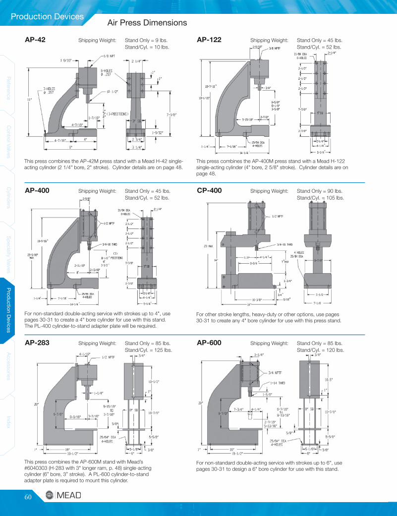
60
ReferenceControlValves
CylindersSpecialtyValves
ProductionDevices
AccessoriesIndex
ReferenceControlValves
CylindersSpecialtyValves
ProductionDevices
AccessoriesIndex
Production Devices
AP-42 Shipping Weight: Stand Only = 9 lbs.Stand/Cyl. = 10 lbs.
AP-122 Shipping Weight: Stand Only = 45 lbs.Stand/Cyl. = 52 lbs.
AP-400 Shipping Weight: Stand Only = 45 lbs.Stand/Cyl. = 52 lbs.
AP-283 Shipping Weight: Stand Only = 85 lbs.Stand/Cyl. = 125 lbs.
AP-600 Shipping Weight: Stand Only = 85 lbs.Stand/Cyl. = 120 lbs.
CP-400 Shipping Weight: Stand Only = 90 lbs.Stand/Cyl. = 105 lbs.
This press combines the AP-42M press stand with a Mead H-42 single-acting cylinder (2 1/4" bore, 2" stroke). Cylinder details are on page 48.
This press combines the AP-400M press stand with a Mead H-122single-acting cylinder (4" bore, 2 5/8" stroke). Cylinder details are onpage 48.
For non-standard double-acting service with strokes up to 4", usepages 30-31 to create a 4" bore cylinder for use with this stand.The PL-400 cylinder-to-stand adapter plate will be required.
For other stroke lengths, heavy-duty or other options, use pages30-31 to create any 4" bore cylinder for use with this press stand.
This press combines the AP-600M stand with Mead’s#6040303 (H-283 with 3" longer ram, p. 48) single-actingcylinder (6” bore, 3” stroke). A PL-600 cylinder-to-standadapter plate is required to mount this cylinder.
For non-standard double-acting service with strokes up to 6", usepages 30-31 to design a 6" bore cylinder for use with this stand.
Air Press Dimensions
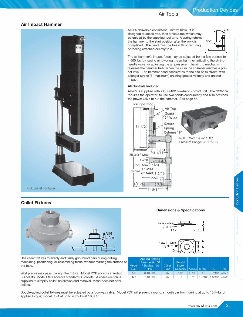
www.mead-usa.com #61
Spec
ialty
Valve
sProd
uctio
nDe
vices
Acce
ssories
Inde
xCy
linde
rsCo
ntrolV
alves
Referenc
eInde
xAc
cess
ories
Prod
uctio
nDe
vices
Spec
ialty
Valve
sCy
linde
rsCo
ntrolV
alves
Referenc
e
Production Devices
Use collet fixtures to evenly and firmly grip round bars during drilling,machining, positioning, or assembling tasks, without marring the surface ofthe bars.
Workpieces may pass through the fixture. Model PCF accepts standard3C collets. Model LS-1 accepts standard 5C collets. A collet wrench issupplied to simplify collet installation and removal. Mead does not offercollets.
Double-acting collet fixtures must be actuated by a four-way valve. Model PCF will prevent a round, smooth bar from turning at up to 10 ft-lbs ofapplied torque; model LS-1 at up to 40 ft-lbs at 100 PSI.
ModelNo.
Applied HoldingPressure @ 100PSI; Max. 120
PSIColletType
RoundStock
Capacity A (sq.) B (sq.) C D (4)PCF 3,400 lbs. 3C 1/2" 4-7/8" 4" 3-7/16" .257"LS-1 7,100 lbs. 5C 1" 7" 5-7/16" 4-9/16" .390"
AH-65 delivers a consistent, uniform blow. It isdesigned to accelerate, then strike a tool which maybe guided by the supplied tool arm. A spring returnsthe hammer to the start position after the work iscompleted. The head must be free with no fixturingor tooling attached directly to it.
The air hammer’s impact force may be adjusted from a few ounces to4,500 lbs. by raising or lowering the air hammer, adjusting the air tripneedle valve, or adjusting the air pressure. The air trip mechanismreleases the hammer head when the air in the chamber reaches a pre-set level. The hammer head accelerates to the end of its stroke, witha longer stroke (6" maximum) creating greater velocity and greaterimpact.
Air Impact Hammer
NOTE: Width is 4-11/16"Pressure Range: 25-175 PSI
Collet Fixtures
All Controls Included
(includes all controls)
AH-65 is supplied with a CSV-102 two-hand control unit. The CSV-102requires the operator to use two hands concurrently and also providesthe power valve to run the hammer. See page 57.
Dimensions & Specifications
Air Tools

62
ReferenceControlValves
CylindersSpecialtyValves
ProductionDevices
AccessoriesIndex
ReferenceControlValves
CylindersSpecialtyValves
ProductionDevices
AccessoriesIndex
Accessories
DimensionsModel Number Length Height Width
#20 4" 1" 1-1/2"
Specifications - RAFKMaterials: Brass-Nickel Plated Body
NBR 70 SealsC72 Dacromet Shaft Clip
Pressure: 15 -145 PSITemperature: 0° F to 160° F (-18° C to 71° C)
Tube PartNo. O.D.
APipe Thd. B L1
L2Min
L2Max CH
RAFK-2x2 1/8 1/8 .217 .827 1.614 1.830 .551RAFK-5/32x2 5/32 1/8 .217 .827 1.614 1.830 .551RAFK-4x2 1/4 1/8 .217 .866 1.614 1.830 .551RAFK-4x4 1/4 1/4 .276 .984 1.850 2.086 .669
ModelNumber A B C E F G H I J KRAF-5/32x2 1/8 NPFT 5/32" .511 .780 1.26 .433 .591 .433 .843 1.24RAF-4x2 1/8 NPFT 1/4" .511 .780 1.26 .512 .591 .512 .944 1.33RAF-4x4 1/4 NPFT 1/4" .669 1.02 1.61 .512 .748 .512 1.06 1.50RAF-6x4 1/4 NPFT 3/8" .669 1.02 1.61 .709 .748 .709 1.06 1.57RAF-8x8 1/2 NPFT 1/2" .866 1.14 1.85 .709 .939 .709 1.14 1.73
Ordering and Specification:
Manifold
DIN Connector Hook-Up Diagram(Not Polarity Sensitive)
Female DIN Solenoid Connectors
Specifications - RAFMaterials: Black Anodized Aluminum Body
Zinc Plated Brass FittingsStainless Steel NeedleBuna-N Seals
Pressure: 15 -145 PSITemperature: -14° F to 160° F (-26° C to 71° C)
Cracking Pressure: 5 PSI
Right Angle Flow Controls (RAF and RAFK)Mead’s right-angle flow control valves provide fast, accurate control in a convenient, compact package. Designed specifically for controlling flowto pneumatic actuators, they come standard with push-in fittings, pre-applied Teflon based thread sealant, an adjustment depending on the type,and convenient swivel feature for ease of tubing alignment. Both the RAF and RAFK mount directly to your cylinder’s ports. The RAF adjustmentis a recessed screw driver slot. The RAF-K has a knob adjustment that can be tightened once set. For precision in-line flow controls, see Mead’sDyla-Trol® flow controls on page 56.
Model PVD1 Model PVD2 Model PVD3
Mead’s 11mm Industrial B-type DIN solenoids feature a totallyencapsulated coil with 3 male prongs, allowing fast and easyconnections. A female DIN connector (ordered separately) quicklyattaches to the solenoid’s prongs and is secured by a single screw.
Mead offers 3 types of DIN connectors to facilitate connections to thesolenoid. Model PVD1 is a connector with a 1/2" conduit entry andno lead wires. Model PVD2 also has a 1/2" conduit entry but includes20" of cabled lead wire. Model PVD3 is a strain relief connector thatincludes 72" of cabled lead 18ga wire.
Use the #20 die cast aluminummanifold to simplify piping andcut down on plumbing time. A3/8" NPTF inlet port provides acommon air source for up toeight 1/8" NPTF outlets.
Right Angle Flow Controls, DIN Connectors and Manifold
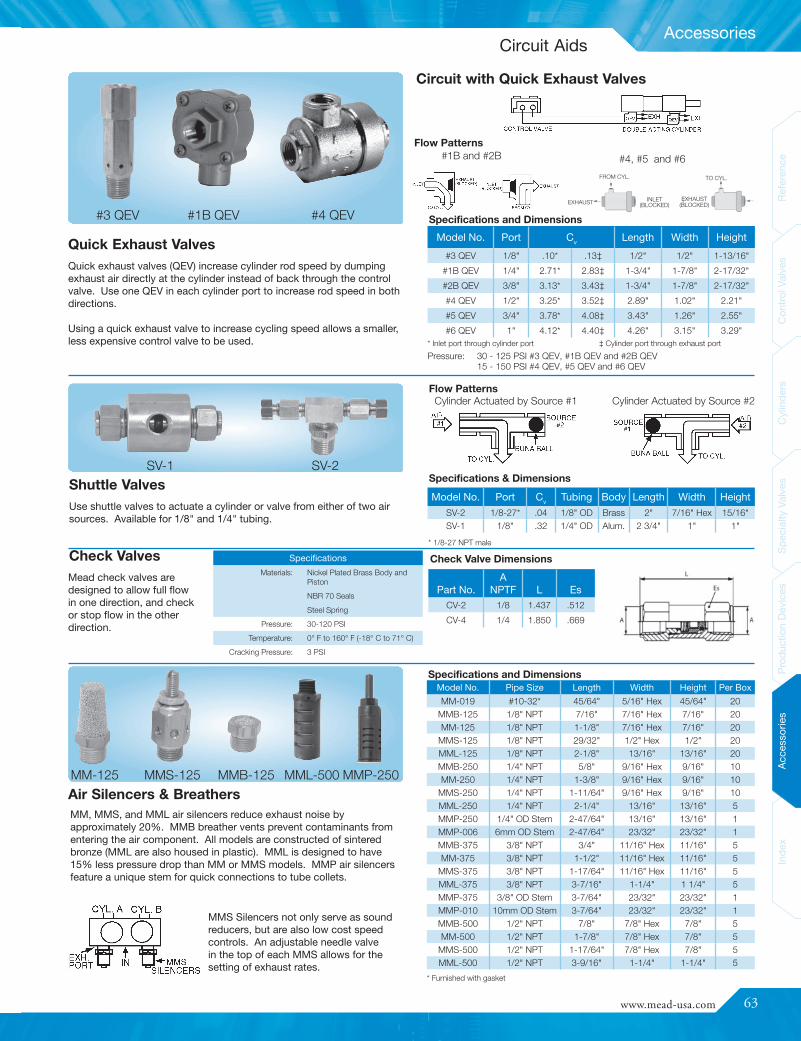
www.mead-usa.com #63
Spec
ialty
Valve
sProd
uctio
nDe
vices
Acce
ssories
Inde
xCy
linde
rsCo
ntrolV
alves
Referenc
eInde
xAc
cess
ories
Prod
uctio
nDe
vices
Spec
ialty
Valve
sCy
linde
rsCo
ntrolV
alves
Referenc
e
Accessories
Model No. Pipe Size Length Width Height Per Box
MM-019 #10-32* 45/64" 5/16" Hex 45/64" 20MMB-125 1/8" NPT 7/16" 7/16" Hex 7/16" 20MM-125 1/8" NPT 1-1/8" 7/16" Hex 7/16" 20
MMS-125 1/8" NPT 29/32" 1/2" Hex 1/2" 20MML-125 1/8" NPT 2-1/8" 13/16" 13/16" 20MMB-250 1/4" NPT 5/8" 9/16" Hex 9/16" 10MM-250 1/4" NPT 1-3/8" 9/16" Hex 9/16" 10
MMS-250 1/4" NPT 1-11/64" 9/16" Hex 9/16" 10MML-250 1/4" NPT 2-1/4" 13/16" 13/16" 5MMP-250 1/4" OD Stem 2-47/64" 13/16" 13/16" 1MMP-006 6mm OD Stem 2-47/64" 23/32" 23/32" 1MMB-375 3/8" NPT 3/4" 11/16" Hex 11/16" 5MM-375 3/8" NPT 1-1/2" 11/16" Hex 11/16" 5
MMS-375 3/8" NPT 1-17/64" 11/16" Hex 11/16" 5MML-375 3/8" NPT 3-7/16" 1-1/4" 1 1/4" 5MMP-375 3/8" OD Stem 3-7/64" 23/32" 23/32" 1MMP-010 10mm OD Stem 3-7/64" 23/32" 23/32" 1MMB-500 1/2" NPT 7/8" 7/8" Hex 7/8" 5MM-500 1/2" NPT 1-7/8" 7/8" Hex 7/8" 5
MMS-500 1/2" NPT 1-17/64" 7/8" Hex 7/8" 5MML-500 1/2" NPT 3-9/16" 1-1/4" 1-1/4" 5
Part No.A
NPTF L EsCV-2 1/8 1.437 .512
CV-4 1/4 1.850 .669
Model No. Port Cv Tubing Body Length Width Height
SV-2 1/8-27* .04 1/8" OD Brass 2" 7/16" Hex 15/16"SV-1 1/8" .32 1/4" OD Alum. 2 3/4" 1" 1"
Model No. Port Cv Length Width Height
#3 QEV 1/8" .10* .13‡ 1/2" 1/2" 1-13/16"
#1B QEV 1/4" 2.71* 2.83‡ 1-3/4" 1-7/8" 2-17/32"
#2B QEV 3/8" 3.13* 3.43‡ 1-3/4" 1-7/8" 2-17/32"
#4 QEV 1/2" 3.25* 3.52‡ 2.89" 1.02" 2.21"
#5 QEV 3/4" 3.78* 4.08‡ 3.43" 1.26" 2.55"
#6 QEV 1" 4.12* 4.40‡ 4.26" 3.15" 3.29"
INLET(BLOCKED)
MM, MMS, and MML air silencers reduce exhaust noise byapproximately 20%. MMB breather vents prevent contaminants fromentering the air component. All models are constructed of sinteredbronze (MML are also housed in plastic). MML is designed to have15% less pressure drop than MM or MMS models. MMP air silencersfeature a unique stem for quick connections to tube collets.
MMS Silencers not only serve as soundreducers, but are also low cost speedcontrols. An adjustable needle valvein the top of each MMS allows for thesetting of exhaust rates.
Flow Patterns
Specifications & Dimensions
#3 QEV #1B QEV
Flow Patterns
Specifications and Dimensions
Specifications and Dimensions
#4 QEV
#1B and #2B #4, #5 and #6
Check Valve Dimensions
EXHAUST(BLOCKED)
TO CYL.FROM CYL.
EXHAUST
Quick Exhaust ValvesQuick exhaust valves (QEV) increase cylinder rod speed by dumpingexhaust air directly at the cylinder instead of back through the controlvalve. Use one QEV in each cylinder port to increase rod speed in bothdirections.
Using a quick exhaust valve to increase cycling speed allows a smaller,less expensive control valve to be used.
Shuttle ValvesUse shuttle valves to actuate a cylinder or valve from either of two airsources. Available for 1/8" and 1/4" tubing.
Check ValvesMead check valves aredesigned to allow full flowin one direction, and checkor stop flow in the otherdirection.
Specifications
Materials: Nickel Plated Brass Body andPiston
NBR 70 Seals
Steel Spring
Pressure: 30-120 PSI
Temperature: 0° F to 160° F (-18° C to 71° C)
Cracking Pressure: 3 PSI
Cylinder Actuated by Source #1 Cylinder Actuated by Source #2
Air Silencers & Breathers
* Inlet port through cylinder port ‡ Cylinder port through exhaust portPressure: 30 - 125 PSI #3 QEV, #1B QEV and #2B QEV
15 - 150 PSI #4 QEV, #5 QEV and #6 QEV
* 1/8-27 NPT male
* Furnished with gasket
SV-1 SV-2
MM-125 MMS-125 MMB-125 MMP-250MML-500
Circuit with Quick Exhaust Valves
Circuit Aids

64
ReferenceControlValves
CylindersSpecialtyValves
ProductionDevices
AccessoriesIndex
Index
ReferenceControlValves
CylindersSpecialtyValves
ProductionDevices
AccessoriesIndex
CAR WASH EQUIPMENT FUEL TREATMENT EQUIPMENT
HOSPITAL EQUIPMENT DENTAL EQUIPMENT
PRINTING PRESSES AUTO ASSEMBLY
LIQUID DISPENSING APPLICATIONS NUCLEAR FUEL REFINING
SEWING MACHINES ROBOTIC APPLICATIONS
SHOE ASSEMBLY EQUIPMENT SAFETY EQUIPMENT
FOOD PROCESS EQUIPMENT AGRICULTURAL EQUIPMENT
Special Applications
Contact Mead today for help solving your special application needs.
When you have a difficult or special application, Mead welcomes the opportunity to design the right product for your application. The following aresome of the applications where we have designed a product to solve a problem.
Custom Products
www.mead-usa.com #65
Index
Inde
xAc
cess
ories
Prod
uctio
nDe
vices
Spec
ialty
Valve
sCy
linde
rsCo
ntrolV
alves
Referenc
e
AAdjustable Lever Valve .......... 20Adjustable Stroke Cylinder..... 48Air Clamps.............................. 48Air Collet Fixtures ................... 61Air Cylinders (see Cylinders)Air Exhaust Silencers.............. 63Air Hammer ............................ 61Air Piloted Valves...............10-13Air Presses (See Presses)Air Timer ................................. 53Air to Electric Converter ......... 54Air Valves (See Valves)Air Tools ................................. 61Anti-Tie Down Devices ........... 57
BBall Actuated Valves..........18-21Binary Valves.......................... 52Bleed Type Valves.................. 18Breathers ................................ 63Button Operated Valves ....14-25
CCam Operated Valves .......20-25Capsula Valves..................16-17Centaur Cylinders..............44-45Clevis Brackets..................33-39Clevis Mounted Cylinders.......26-45Collet Fixtures ........................ 61Compact Cylinders................. 47Controls, Presses ................... 57Controls, Valves ..................4-58Cylinders
See “Cylinder Finder”........... 1Adjustable Stroke ............... 48Clevis Mounted .............26-44Compact............................. 47Cushioned .....................26-44Double Acting................26-44Double Rod ...................26-44Dyna-Mation..................28-33End of Stroke Sensors ....... 54Flange Mount (Front) .....26-33Flange Mount (Rear) ......26-33Flat Type............................. 49Flush Mounted ..............26-44Foot Mounted................26-50
Cylinders (Continued)HD1 Series ....................34-41HD Series ......................42-43Hydraulic .......................26-42Interchangeable (JIC) ....34-43Interchangeable (NFPA) .....34-43Inter-piloted ...................29-44Low Profile.......................... 47Miniature........................49-56Non-Lubricated..............26-43Nose Mounted ...............26-43Pivot Brackets ...............26-43Pivot Mounted ...............26-43Reed Switches...............29-47Rod Clevis .....................31-42Rod Eyes .......................31-42Round Type ...................44-45Single Acting....................... 48Space Saver ....................... 47Spring Return.................49-50Square End......................... 26Stroke Sensors ................... 54Tie Rod Type .................26-42Trunnion Mounted .........26-42
DDIN Connector........................ 62DIN Connector Solenoid .....4-20Directional Control Valves .....4-25Double Acting Cylinders
Centaur ..........................44-45Cushioned......................26-42Double Rod....................26-42DM1 ...............................26-33DM2 ...............................26-44Dyna-Mation ..................28-33Interchangeable (NFPA)......34-43Low Profile.......................... 47Non-Lubricated..............26-43Round Type ...................26-44Space Saver ....................... 47Tie Rod Type .................26-44
Double Air Piloted Valves ..11-22Double Bleed Valves .............. 18Double Rod Cylinders .......26-33Double Solenoid Valves.......4-21Dura-Matic Valve.................... 18
Dyla-Trol Flow Controls.......... 56Dyna-Coil Valves .................... 52Dyna-Mation Cylinders......28-33
EElectric Switches .................... 54Emergency Stop Valves ....21-23End of Stroke Sensors ........... 54Exhaust Silencers................... 63
FFingertip Operated Valves ...21-25Flange Mounted Cylinders
Front ..............................26-41Rear ...............................26-41
Flat Cylinders.....................47-50Flow Control Valves
Air Exhaust Silencer Type... 63Built-In Valve....................... 18Dyla-Trol ............................. 56Inline Type .......................... 56Right Angle ......................... 62
Flush Mounted Cylinders ..26-41Foot Mounted Cylinders....26-41Foot Operated Valves
Pedal Type.....................15-21Treadle Type....................... 25
Four-Way Valves .................4-25G
General Purpose Valves ....24-25H
HD1 Cylinders ...................34-41Solid State Switches .........29-47Hammers, Air.......................... 61Hand Operated Valves ......15-56Heavy Duty Cylinders ........34-43Hydraulic Cylinders ...........26-44
IImpulse Relay Valves.............. 53Isonic Valves........................4-13Isonic 2 & 3-Way Valves........4-9Isonic 4-Way Valves ..........10-11
JJIC Interchangeable Cylinders . 28-43
KKnob Actuated Valves .......20-55
LLever Operated Valves ......15-52
Lockout Valve ......................... 51Low Stress Valve.................... 19
MManifold PowerStrip................ 12Manifold Valves .................... 4-21Manifolds................................ 62Manual Overrides ................4-15Micro-Line Valves..............22-23Mufflers................................... 63
NNormally Closed Valves.......4-55Normally Open Valves .........4-55Nova Valves.......................14-15
OOne-Way Roller Leaf Valves ...20-22
PPalm Operated Valves.......19-23Panel Mounted Valves.......21-35Pilot Valves ........................10-24Pin Plunger Operated Valves ..20-23Plunger Operated Valves...20-23Poppet Type Valves ............5-25Press Controls........................ 57Presses, Air
Arbor Type.......................... 58Bench.................................. 58Column Type ...................... 58Stand .................................. 58
PTO Valves............................. 55Pulse Valves ........................... 53Pushbutton Operated Valves ..15-20
QQuick Exhaust Valves............. 63
RReed Switches ..................29-47Rod Actuated Valves.........20-22Rod Alignment Couplers ........ 29Rod Clevises .....................29-44Rod Eyes ...........................26-31Roller Operated Valves......20-22Round Cylinders..................... 44
Product Index
66
ReferenceControlValves
CylindersSpecialtyValves
ProductionDevices
AccessoriesIndex
Index
ReferenceControlValves
CylindersSpecialtyValves
ProductionDevices
AccessoriesIndex
SSafety Devices...................21-23Selector Valve......................... 52Shuttle Valves......................... 63Single Solenoid Valves
Direct Acting ....................4-52Piloted..............................4-52
Slide Type Valves ................... 51Solenoid Valves
DIN Connector Type........4-23Double .............................4-23Plug -In Type ...................4-23Single (Direct)...................4-23Single (Piloted) ................4-23
Speed Control Valves(See Flow Control Valves)
Spool Type Valves...............4-25Spring Return Cylinders ......... 54Stacked Valves........ 4-13, 18-19Sub-Base Mounted Valves .....16-18Switches
Air Operated ........ 8-17, 18-21Bleed Limit.......................... 18Electric ................................ 54Limit ...............................20-23Reed ..............................29-47Solid State .....................29-47
TThree Position Valves ............. 21Three Way Valves................4-23Timers, Air .............................. 53Toggle Lever Valves ..........20-23Treadle Type Foot Valve......... 25Trunnion Mounted Cylinders...28-44Two-Hand Anti Tie Down ....... 57
Twist Valves.......................20-23Two Position Valves ............4-52Two Way Valves
Poppets ...........................5-25Solenoid...........................4-52
VValves
See “Valve Finder”.............2-3ACV Valve ........................... 55Adjustable Lever ............20-22Air Piloted ......................10-24Air to Electric Converter...... 54Ball Actuated .................20-23Bleed Type.......................... 14Button Operated............15-23Cam Operated ...............20-23Capsula..........................16-17Dash Mounted .................... 55DIN Type............................. 46Directional Control...........4-23Double Air Pilot ..............10-21Double Bleed ...................... 14Double Solenoid ..............4-20Dura-Matic.......................... 18Dyal-Trol ............................. 56Dyna-Coil ............................ 52Electric Switches ................ 54Emergency Stop ............21-23Fingertip Operated.............. 21Flow Control ....................... 62Flow Control Air ExhaustSilencers ............................. 63Four Way .........................4-21Hand Operated ..............15-26
Valves (Continued)Impulse Relays ................... 53Knob Actuated...............20-23Lever Operated..............15-23LTV Type........................20-21Manifold...........................4-21Manual Overrides.............4-15MHL Valves......................... 51Micro-Line........................... 22Nova ................................... 14One Way Roller Leaf ......20-22Palm Operated...............20-21Panel Mounted ..............20-56Piloted..............................8-22Pin Plunger ....................20-23Plug In Solenoid...............4-22Poppet Type ....................7-23Press Control ...................... 57Pressure Held ..................... 16Pressure Released.............. 16Pressure Piloted ............10-16PTO..................................... 55Pulse Type .......................... 53Push Button Operated...20-25Quick Exhaust..................... 63Rod Actuated.................20-23Roller Actuated ..............20-23Safety.............................20-23Selector Valve................20-23Shuttle................................. 63Time Delay .......................... 53Toggle Lever ..................20-23Twist ..............................20-23Two Position ....................4-25Two Way..........................4-25Vacuum............................4-25
Product Index

www.mead-usa.com #67
Index
Inde
xAc
cess
ories
Prod
uctio
nDe
vices
Spec
ialty
Valve
sCy
linde
rsCo
ntrolV
alves
Referenc
e
Notes

68
ReferenceControlValves
CylindersSpecialtyValves
ProductionDevices
AccessoriesIndex
Index
ReferenceControlValves
CylindersSpecialtyValves
ProductionDevices
AccessoriesIndex
Notes
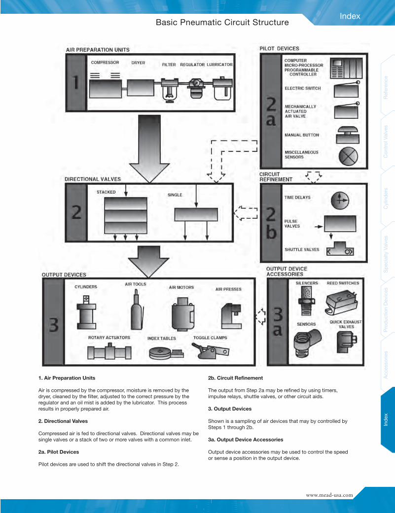
Index
Inde
xAc
cess
ories
Prod
uctio
nDe
vices
Spec
ialty
Valve
sCy
linde
rsCo
ntrolV
alves
Referenc
e
www.mead-usa.com #
Basic Pneumatic Circuit Structure
1. Air Preparation Units
Air is compressed by the compressor, moisture is removed by thedryer, cleaned by the filter, adjusted to the correct pressure by theregulator and an oil mist is added by the lubricator. This processresults in properly prepared air.
2. Directional Valves
Compressed air is fed to directional valves. Directional valves may besingle valves or a stack of two or more valves with a common inlet.
2a. Pilot Devices
Pilot devices are used to shift the directional valves in Step 2.
2b. Circuit Refinement
The output from Step 2a may be refined by using timers,impulse relays, shuttle valves, or other circuit aids.
3. Output Devices
Shown is a sampling of air devices that may by controlled bySteps 1 through 2b.
3a. Output Device Accessories
Output device accessories may be used to control the speedor sense a position in the output device.
• Actuators
• Valves
• Production Devices
• Safety
Setting a new standard for:
Full Line Catalog
Mead
FluidDynam
icsFullLineCatalog
Bim
baManufacturing
Com
panyMEA
D-FL-515
Your stocking distributor is:
Worldwide distribution means there is a professional stocking
Bimba distributor nearby ready to service your needs.
Catalog
Bimba Manufacturing Headquarters
P.O. Box 68 Monee, Illinois 60449-0068
Phone: 708-534-8544 Toll Free: 800-44-BIMBA Fax: 708-235-2014
Email: [email protected] www.bimba.com
PNEUMATIC • ELECTRIC • HYDRAULIC ACTUATORS FITTINGS — MANIFOLDS — VALVES — AIR PREPARATION — SAFETY & PRODUCTION
BIMBA BRANDS I ACRO I MEAD I MFD I PNEUMADYNE I TRD
Mead Fluid Dynamics
4114 North Knox Avenue Chicago, IL 60641
Phone: 773-685-6800 Toll Free: 877-MEAD-USA Fax: 773-685-7002
Email: [email protected] www.mead-usa.com
© Copyright 2015 Bimba Manufacturing Company. MEAD-FL-515 Effective May 2015. All Rights Reserved.