FULL D IGITAL S ERVODRIVE FOR BRUSHLESS SERVOMOTORS ... · vfd 400 installation manual...
19
VFD 400 Installation Manual MNINVFD4_0F-UK02 1 FULL DIGITAL SERVODRIVE FOR BRUSHLESS SERVOMOTORS VFD400F SERIES INSTALLATION MANUAL DOCUMENT NUMBER: MNINVFD4_0F-UK02 EDITION: 02 AUTHOR: A. Montanaro, A. Kanev DATE: July 2004 The material in this manual is for informational purposes only and is subject to change without notice. All rights reserved. This document shall not be reproduced, either entirely or in part, without written authorization.
Transcript of FULL D IGITAL S ERVODRIVE FOR BRUSHLESS SERVOMOTORS ... · vfd 400 installation manual...

VFD 400 Installation Manual
MNINVFD4_0F-UK02 1
FULL DIGITAL SERVODRIVE
FOR BRUSHLESS SERVOMOTORS
VFD400F SERIES
INSTALLATION MANUAL
DOCUMENT NUMBER: MNINVFD4_0F-UK02 EDITION: 02 AUTHOR: A. Montanaro, A. Kanev DATE: July 2004 The material in this manual is for informational purposes only and is subject to change without notice.
All rights reserved. This document shall not be reproduced, either entirely or in part, without written authorization.

VFD 400 Installation Manual
MNINVFD4_0F-UK02 2
Edition Date Remarks
01 04/2004 Preliminary Edition 02 07/2004 Last Edition

VFD 400 Installation Manual
MNINVFD4_0F-UK02 3
CONTENTS
1. External connections........................................................................................................................................... 4 1.1. Power connector - X1 ................................................................................................................................. 7 1.2. Auxiliary supply connector - X2................................................................................................................. 9 1.3. Brake connector - X3 (Option) ................................................................................................................... 9 1.4. Control unit connector - X7 ...................................................................................................................... 10 1.5. Encoder emulation or encoder - linear scale input connector – X5 ....................................................... 11 1.6. Resolver connector – X6........................................................................................................................... 11 1.7. Fieldbus connector – X4 (CAN VERSION ONLY)................................................................................. 12 1.8. Fieldbus connector – X4 (PROFIBUS VERSION ONLY) ...................................................................... 12 1.9. RS232 Cables............................................................................................................................................ 13 1.10. Table Of Conductor Cross-Sections ..................................................................................................... 14
2. Mechanical Installation .................................................................................................................................... 15 Appendix A – Single Fase Operation........................................................................................................................ 19

VFD 400 Installation Manual
MNINVFD4_0F-UK02 4
1. External connections
VFD400FC Front View VFD400FP Front View
CAUTION !
CAUTION !
X1 X1
X2 X2
X3 X3
X4 X4
X5 X5
X6 X6
X7 X7
VFD 400 Installation Manual
MNINVFD4_0F-UK02 5
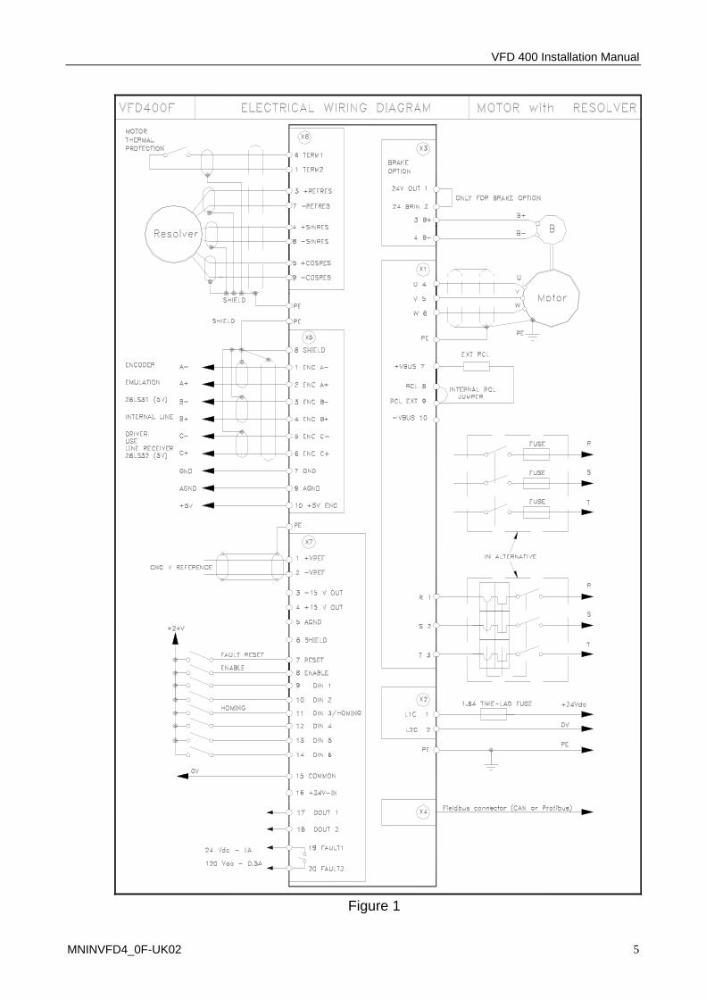
Figure 1

VFD 400 Installation Manual
MNINVFD4_0F-UK02 6
Figure 2

VFD 400 Installation Manual
MNINVFD4_0F-UK02 7
1.1. Power connector - X1
Connector X1 is dedicated to connections of power supply, motor and clamp resistor.
1.1.1. Motor connection
• Connect the motor cables to terminals 4, 5 and 6 observing the correct pole connection.
• Connect the PE cable to one of the two PE screw terminals on the front panel.
1.1.2. Clamp resistor connection
• When using the internal resistor connect terminals 8 and 9. • When using an external resistor, connect the resistor between terminals 7 and 9 (see
fig. 1).
1.1.3. Mains connection
• Connect terminals 1, 2 and 3 between three phases at 230 Vac line to line mains connection.
• Insert the fuses specified in figure 1 in series with the cables. • Connect the PE cable to one of the two PE screw terminals on the front panel.
The IT connection are adviced against because it's very hard verify the overcoming of the limits in transitory regimen.
Power connector X1
Pin Ref. Description 1 R Three phase power supply (max 230 VAC)
2 S Three phase power supply (max 230 VAC)
3 T Three phase power supply (max 230 VAC)
4 U Motor phase U
5 V Motor phase V
6 W Motor phase W
7 +VBUS + DC bus
8 RCL Internal clamp resistor
9 RCL EXT Internal/external clamp resistor 10 -VBUS - DC bus
Table 1.1

VFD 400 Installation Manual
MNINVFD4_0F-UK02 8
TT at 400Vac
IT at 400Vac

VFD 400 Installation Manual
MNINVFD4_0F-UK02 9
1.2. Auxiliary supply connector - X2
Connetions for an external auxiliary power supply at 24 Vdc ± 15% – 1,5A max
1.3. Brake connector - X3 (Option)
This option may be used with motors including an electromagnetic brake.
• The drive automatically cuts off power and releases the electromechanic brake when connection between pins 1 and 2 is open.
• Connect a potential free contact emergency switch between pins 1 and 2, or jumper them.
• Brake supply input: connect between pin 2 (24 Vdc, 2 A) and pin 4 (GND 24 Vdc, 2 A).
VFD400 F 03 VFD400 F 05 VFD400 F 07 VFD400 F 10
Resistence [Ω] 56 33 15 15
Nominal Power [W] 110 110 220 220
Tp(peak) [V] 400 400 400 400
Tp (o) [V] 1.8 1.8 1.8 1,8
Resistors Model / SIR SRC +
SB1G20 A+T / IRE CBR 180
Dimensions [mm] / 29x165 / 195x45x11,5
Table1.3.2
Brake connector X3
Pin Ref. Description
1 24VOUT Internal brake supply (24V DC, 0.8A max)
2 24BRIN Brake supply input (24V DC, 2A max)
3 B+ Brake output +
4 B- Brake output – (GND 24 Vdc)
Table1.3.1
Auxiliary supply connector X2
Pin Ref. Description
1 L1C aux. Supply +24 Vdc ± 15% – 1,5 A max
2 L2C aux. Supply GND 24 Vdc
Table 1.2
2
1

VFD 400 Installation Manual
MNINVFD4_0F-UK02 10
1.4. Control unit connector - X7
• VREF+/VREF-: analog reference input (+/-10 V differential). It is used to control the motor speed when the converter is configured in Analog Speed Mode or the motor current when the converter is configured in Analog Current Mode.
• ENABLE: digital input (15÷24V, 20 mA) to enable the power stage of the converter. • RESET: digital input (15÷24V, 20 mA) to reset fault. • FAULT1/FAULT2: relay contact normally closed when the converter is ready to
switch-on or is running. The contact is open when the converter is not ready to switch-on or a fault condition has occurred.
Control unit connector X7
Pin Ref. Description
1 VREF+ Speed (or current) reference input +
2 VREF- Speed (or current) reference input -
3 -15V-OUT Auxiliary voltage output (50mA max.)
4 +15V-OUT Auxiliary voltage output (50mA max.)
5 AGND Analog ground
6 SHIELD Shield
7 RESET Fault reset
8 ENABLE Power enable input
9 DIN1 Digital input 1
10 DIN2 Digital input 2
11 DIN3 Digital input 3 – Home switch
12 DIN4 Digital input 4
13 DIN5 Digital input 5
14 DIN6 Digital input 6
15 GNDCMD 24V common signal
16 +24V-IN 24V input
17 DOUT1 Digital output 1
18 DOUT2 Digital output 2
19 FAULT1 Drive ready signal output (relay contact)
20 FAULT2 Drive ready signal output (relay contact)
Table1.4

VFD 400 Installation Manual
MNINVFD4_0F-UK02 11
1.5. Encoder emulation or encoder - linear scale input connector – X5
The signals on this connector are bidirectional. It is possible to configure the encoder as input, for external encoder, or as output, for motor feedback position.
I motori con encoder sincos possono essere di diverso tipo. Il cablaggio mostrato è valido per encoder con tracce assolute (chiamate nella tabella tracce lente). In genere per le righe ottiche queste tracce non sono disponibili. In questo caso il motore potrebbe essere dotato di sensori di Hall i quali devono essere collegati al connettore X4 (par.
1.6. Resolver connector – X6
Encoder emulation connector X5
Pin Ref. Description
1 ENC-A- RS422 A – signal
2 ENC-A+ RS422 A + signal
3 ENC-B- RS422 B – signal
4 ENC-B+ RS422 B + signal
5 ENC-C- RS422 C – signal (zero marker)
6 ENC-C+ RS422 C + signal (zero marker)
7 GND Ground
8 SHIELD Shield
9 AGND Analog ground
10 +5V-ENC +5V encoder supply (max 150 mA)
Table 1.5
Resolver connector X6
Pin Ref. Description
1 THERM2 Motor thermal protection (2)
2 N.C. Not connected
3 + REFRES + resolver reference
4 + SINRES + resolver sinus signal
5 + COSRES + resolver cosinus signal
6 THERM1 Motor thermal protection (1)
7 - REFRES - resolver reference
8 - SINRES - resolver sinus signal
9 - COSRES - resolver cosinus signal
Table 1.6

VFD 400 Installation Manual
MNINVFD4_0F-UK02 12
1.7. Fieldbus connector – X4 (CAN VERSION ONLY)
1.8. Fieldbus connector – X4 (PROFIBUS VERSION ONLY)
CAN connector X4
Pin Ref. Description
1 N.C. Not connected
2 CANL Can Bus Low
3 N.C. Not connected
4 RX232 RS232 RX signal
5 N.C. Not connected
6 GND RS232 ground
7 CANH Can Bus High
8 TX232 RS232 TX signal
9 N.C. Not connected
Table 1.7
Profibus connector X4
Pin Ref. Description
1 SHIELD Shield
2 RX232 RS232 RX signal
3 RxD/TxD-P Receive/Transmit Data – plus
4 N.C. Not connected
5 DGND Data ground
6 VP Supply voltage – plus (+5V iso)
7 TX232 RS232 TX signal
8 RxD/TxD-N Receive/Transmit Data – minus
9 GND RS232 ground
Table 1.8

VFD 400 Installation Manual
MNINVFD4_0F-UK02 13
1.9. RS232 Cables
Used to connect a PC RS232 serial line. • RS232: - maximum cable length: 10 meters;
- max capacitance: 2500 pF; - shielded cable.
Fig. 1.9.1 – VFD400C (CAN) RS232 cable
Fig. 1.9.2 – VFD400P (PROFIBUS) RS232 cable

VFD 400 Installation Manual
MNINVFD4_0F-UK02 14
1.10. Table Of Conductor Cross-Sections
Function Connectors VFD400Fx03 VFD400Fx05 VFD400Fx07 VFD400Fx10
Clamp resistor cable X1 1.5 mm2
Motor cable X1 1.5 mm2 2.5 mm2
Power supply cable X1 1.5 mm2 2.5 mm2
Brake cable, brake supply and services
X2, X3 0.5 ÷ 1 mm2
Resolver cable X6 0.14 ÷ 0.22 mm2
Control unit signal cable
X5, X7 0.14 mm2
Table 1.10

VFD 400 Installation Manual
MNINVFD4_0F-UK02 15
2. Mechanical Installation Use the brackets and the screws supplied with the converter for mounting VFD300. • fix the bottom bracket to the mounting panel with two screws; • place the converter on the bottom bracket; • place and fix with a screw the top bracket.
M4 holes
=
c1
d
170
d b1 b
All dimensions in mm
VFD3CRA2003000C A Type
= =
m c2 c1 c
a
Fig.
CAUTION ! X3
X7
70 252 206 16.5 14 39.5 238 +1 -0
a b b1 c c2 c1 d
X2 X6
X5
X1 X4
LD
k
=
k2 c = =
k1
=
g =
Allow a free space for assembling the connecting cables e
174 5.5 4.5 63.5 2 Ø5.5 e e1 g k k1 k2 m
e1
Fig. A
VFD3CRA2005000C 252 B 80 206 24 39.5 63.5 238 16.5 190 +1 -0 194 5.5 12 4.5 Ø5.5
Fig. 2.1 – VFD400 FC 03 CAN version VFD400 FC 05 CAN version

VFD 400 Installation Manual
MNINVFD4_0F-UK02 16
24 VFD3CRA2010000C 206 C 80 271 23 41.5 +1 -0 16.5 39.5 257 194 190 5.5 Ø5.5 63.5 12 4.5
190
M4 holes
=
c1
d b b1
d
VFD3CRA2007000C
All dimensions in mm
C Type Fig.
80 271 206 24 16.5 39.5 257 +1 -0
Fig. C
c1 a
=
c m
a b b1 c
b2
CAUTION ! X3
c2
c2 c1 d
X7
X2
X1
X6
X5
X4
LD
g =
k1
=
k c =
b3
k2 =
Allow a free space for assembling the connecting cables e
194 5.5 12 63.5 4.5 Ø5.5 e e1 g k k1 k2 m
e1
b3 41.5 23
b2
Fig. 2.2 – VFD400 FC 07 CAN version VFD400 FC 10 CAN version

VFD 400 Installation Manual
MNINVFD4_0F-UK02 17
Fig. A
16.5 VFD3CRA4005000C 80 B 252 206 24 39.5 63.5 194 +1 -0 238 190 5.5 12 4.5 Ø5.5
174 5.5 4.5 63.5 2 Ø5.5 e e1 g k k1 k2 m
e1
M4 holes
=
c1
d
170
d b1 b
All dimensions in mm
VFD3CRA4003000C A Type
= =
m c2 c1 c
a
Fig.
CAUTION ! X3
X7
70 252 206 16.5 14 39.5 238 +1 -0
a b b1 c c2 c1 d
X2 X6
X5
X1 X4
LD
k
=
k2 c = =
k1
=
g =
Allow a free space for assembling the connecting cables e
Fig. 2.3 – VFD400 FP 03 PROFIBUS version VFD400 FP 05 PROFIBUS version

VFD 400 Installation Manual
MNINVFD4_0F-UK02 18
24 VFD3CRA4010000C 206 C 80 271 23 41.5 16.5 39.5 257 194 190 5.5 Ø5.5 63.5 12 4.5 All dimensions in mm
+1 -0
X6
X5
X4
LD
g =
k1
=
k c =
b3
k2 =
Allow a free space for assembling the connecting cables e
194 5.5 12 63.5 4.5 Ø5.5 e e1 g k k1 k2 m
e1
b3 41.5 23
b2 190
M4 holes
=
c1
d b b1
d
VFD3CRA4007000C C Type Fig.
80 271 206 24 16.5 39.5 257 +1 -0
Fig. C
c1 a
=
c m
a b b1 c
b2
CAUTION ! X3
c2
c2 c1 d
X7
X2
X1
Fig. 2.4 – VFD400 FP 07 PROFIBUS version VFD400 FP 10 PROFIBUS version

VFD 400 Installation Manual
MNINVFD4_0F-UK02 19
Appendix A – Single Fase Operation
O
µ
Figure A1 – Connection for VFD 400 F in single phase operation