
Brushless internal rotor servomotors series ECI...Brushless servomotors series ECI Edition 2019-11 5...
84
the engineer’s choice Brushless internal rotor servomotors series ECI Drive solutions | Industrial drive engineering Product Catalogue 2019-11
Transcript of Brushless internal rotor servomotors series ECI...Brushless servomotors series ECI Edition 2019-11 5...
the engineer’s choice
Brushless internal rotor servomotors series ECIDrive solutions | Industrial drive engineering
Product Catalogue 2019-11
2
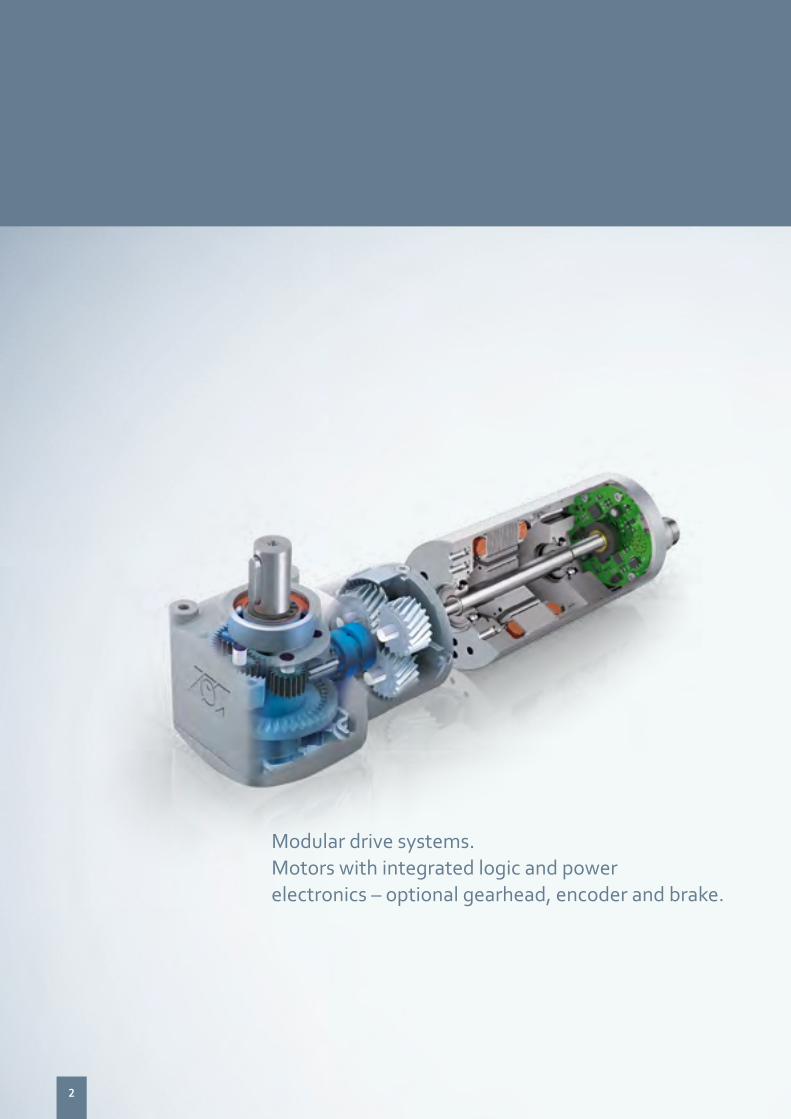
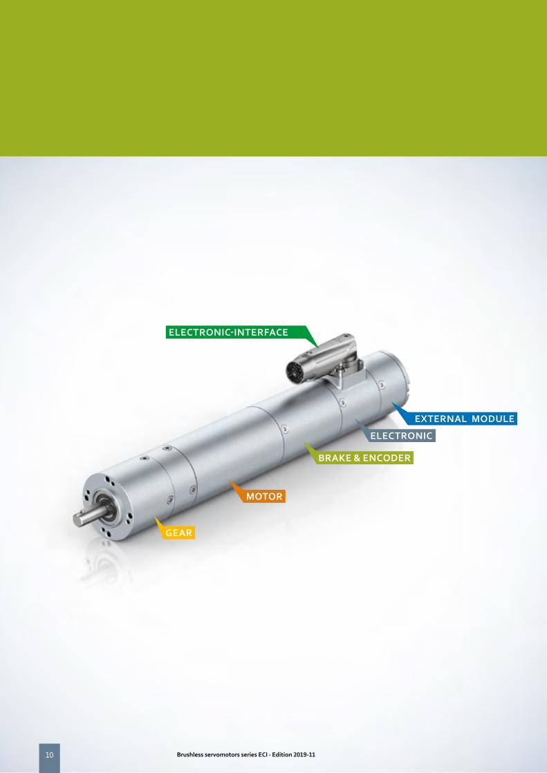
Modular drive systems. Motors with integrated logic and power electronics – optional gearhead, encoder and brake.
3Brushless servomotors series ECI · Edition 2019-11
Page Page
Information 4 About ebm-papst / GreenIntelligence 4
Our success story 5
Overview of ECI motors 6
Definitions for ECI servomotor 8
Overview of ECI motors / modular system 11
ECI Servomotor 12 ECI-42.XX-K1 14
ECI-63.XX-K1 18
ECI-63.XX-K3 22
ECI-63.XX-K4 26
ECI-63.XX-K5 30
ECI-80.XX-K1 34
Control electronics 38 VTD-XX.XX-K3 (speed) 40
VTD-XX.XX-K4S (position) 42
VTD-60.13-K5SB (CANopen) 44
VTD-60.35-K5SB (CANopen) 46
Gearheads 48 Information about gearheads 50
NoiselessPlus 42 (planetary gearhead) 52
NoiselessPlus 63 (planetary gearhead) 54
Performax®Plus 42 (Planetary gearhead) 56
Performax®Plus 63 (Planetary gearhead) 58
Optimax 42 (Planetary gearhead) 60
Optimax 63 (Planetary gearhead) 62
EtaCrown® 52 (Crown gearhead) 64
EtaCrown® 75 (Crown gearhead) 66
EtaCrown®Plus 42 (Crown gearhead) 68
EtaCrown®Plus 63 (Crown gearhead) 70
Accessories 72 Commissioning tools (K4 / K5) 74
Brakes 76
Encoder 78
Information 80 Operating factor, lifetime, efficiency 80
Agents around the world 83
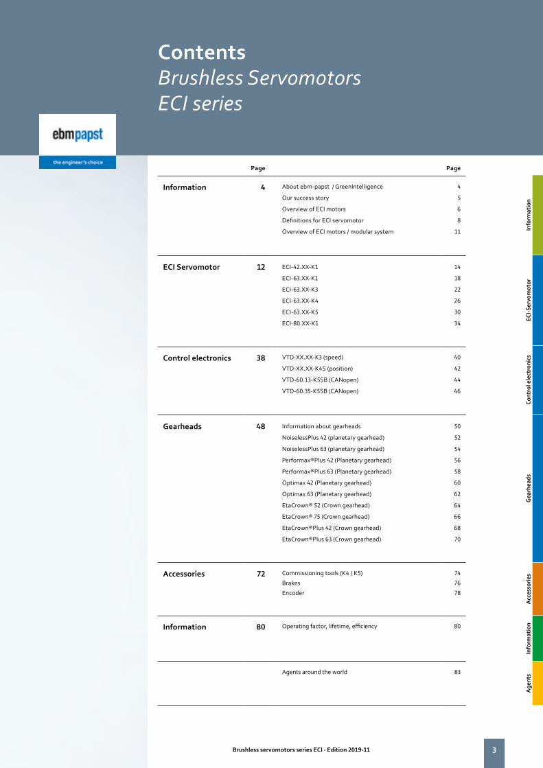
ContentsBrushless ServomotorsECI series
Info
rmat
ion
Info
rmat
ion
ECI-S
ervo
mot
or
ECI-S
ervo
mot
ors
Cont
rol e
lect
roni
cs
Cont
rol e
lect
roni
cs
Gea
rhea
ds
Get
riebe
Acc
esso
ries
Acc
esso
ries
Info
rmat
ion
Info
rmat
ion
Age
nts
Vert
retu
ngen

44
Six reasons that make us the ideal partner:
Our systems expertise: as experts in advanced motor technology, electronics and aerodynamics, we provide system solutions from a single source.
Our spirit of invention: our 600 engineers and technicians will develop a solution that precisely fits your needs.
Our lead in technology: with our EC technology and GreenIntelligence, we combine the highest energy efficiency with the advantages of IoT and digital networking.
Closeness to our customers: at 49 sales offices worldwide.
Our standard of quality: our quality management is uncompromising, at every step in every process.
Our sustainable approach: we assume responsibility with our energy-saving products, environmentally-friendly processes, and social commitment.
About ebm-papst.ebm-papst is a leader in ventilation and drive engineering technology and a much sought-after engineering partner in many industries. With around 20,000 different products, we have the perfect solution for practically every requirement. We believe the consistent further development of our highly-efficient GreenTech EC technology provides our customers with the best opportunities for the future in indus-trial digitization. With GreenIntelligence, ebm-papst already offers intelligent networked complete solutions that are unique anywhere in the world today.
Why do our customers look so happy? Because when it comes to the Internet of Things and the digital transformation, we provide them with a clear competitive edge with GreenIntelligence for intelligent control and interconnection of fans, drives and systems to make appli-cations more powerful, processes more efficient, businesses more successful and their customers more satisfied.
For the wide range of automation tasks needed in industrial drive technology, what you need most is an experienced partner who under-stands your needs. The drive experts at ebm-papst have detailed applications expertise and, thanks to GreenIntelligence, can offer drive solutions with intelligent networking capabilities that cater for all requirements perfectly.
GreenIntelligence. Making Engineers Happy.
Here is how much Green Intelligence there is in ECI Motors:
– integrated logic & power electronics – network functionality – Master/slave functionality – Condition monitoring – Predictive maintenance
Anna exploits the possibilities of the Industrial Internet of Things throughout her logistics and production processes.
Info
rmat
ion
Info
rmat
ion
5Brushless servomotors series ECI · Edition 2019-11 5
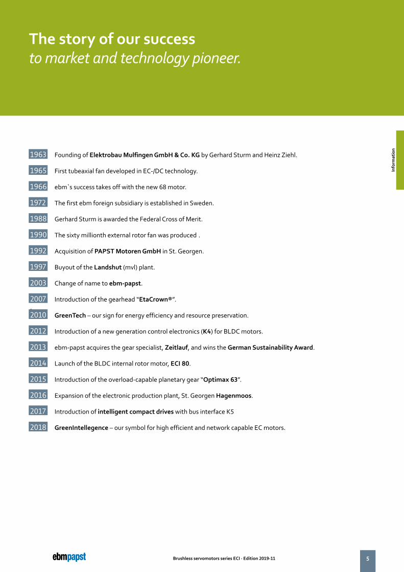
The story of our successto market and technology pioneer.
1963 Founding of Elektrobau Mulfingen GmbH & Co. KG by Gerhard Sturm and Heinz Ziehl.
1965 First tubeaxial fan developed in EC-/DC technology.
1966 ebm`s success takes off with the new 68 motor.
1972 The first ebm foreign subsidiary is established in Sweden.
1988 Gerhard Sturm is awarded the Federal Cross of Merit.
1990 The sixty millionth external rotor fan was produced..
1992 Acquisition of PAPST Motoren GmbH in St. Georgen.
1997 Buyout of the Landshut (mvl) plant.
2003 Change of name to ebm-papst.
2007 Introduction of the gearhead “EtaCrown®”..2010 GreenTech – our sign for energy efficiency and resource preservation.
2012 Introduction of a new generation control electronics (K4) for BLDC motors.
2013 ebm-papst acquires the gear specialist, Zeitlauf, and wins the German Sustainability Award.
2014 Launch of the BLDC internal rotor motor, ECI 80.
2015 Introduction of the overload-capable planetary gear “Optimax 63”.
2016 Expansion of the electronic production plant, St. Georgen Hagenmoos.
2017 Introduction of intelligent compact drives with bus interface K5
2018 GreenIntellegence – our symbol for high efficient and network capable EC motors.
Info
rmat
ion
Info
rmat
ion
6 Brushless servomotors series ECI · Edition 2019-11
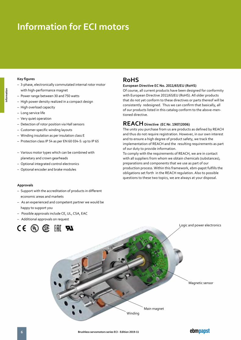
Key figures
– 3-phase, electronically commutated internal rotor motor
with high-performance magnet
– Power range between 30 and 750 watts
– High power density realized in a compact design
– High overload capacity
– Long service life
– Very quiet operation
– Detection of rotor position via Hall sensors
– Customer-specific winding layouts
– Winding insulation as per insulation class E
– Protection class IP 54 as per EN 60 034-5: up to IP 65
– Various motor types which can be combined with
planetary and crown gearheads
– Optional integrated control electronics
– Optional encoder and brake modules
Approvals
– Support with the accreditation of products in different
economic areas and markets
– As an experienced and competent partner we would be
happy to support you
– Possible approvals include CE, UL, CSA, EAC
– Additional approvals on request
Logic and power electronics
Magnetic sensor
Main magnetWinding
Information for ECI motors
RoHSEuropean Directive EC No. 2011/65/EU (RoHS) Of course, all current products have been designed for conformity with European Directive 2011/65/EU (RoHS). All older products that do not yet conform to these directives or parts thereof will be consistently redesigned. Thus we can confirm that basically, all of our products listed in this catalog conform to the above-men-tioned directive.
REACH Directive (EC Nr. 1907/2006)The units you purchase from us are products as defined by REACH and thus do not require registration. However, in our own interest and to ensure a high degree of product safety, we track the implementation of REACH and the resulting requirements as part of our duty to provide information. To comply with the requirements of REACH, we are in contact with all suppliers from whom we obtain chemicals (substances), preparations and components that we use as part of our production process. Within this framework, ebm-papst fulfills the obligations set forth in the REACH regulation. Also to possible questions to these two topics, we are always at your disposal.
Info
rmat
ion
Info
rmat
ion
7Brushless servomotors series ECI · Edition 2019-11
The data in this catalog contain product specifications, but are not a guarantee of particular properties.
All information is based on the measuring conditions mentioned below. Operation of motors using reference electronics at an ambient temperature of max. 40°C when attached (thermally conductive) to a free-standing metal plate of the following size:
For motor ECI 42: 126 x 126 x 10 mm.For motor ECI 63: 189 x 189 x 10 mm.For motor ECI 80: 240 x 240 x 10 mm.
It should be noted that a brake integrated in the motor or a gearbox mounted on the motor will change the specification values
The nominal operating point is the basis for the electro- magnetic design of the motor from the point of view of the maximum possible continuous output of the motor and is specified by the nominal val-ues described here.
The values mentioned are typical values for the design in question and are also subject to the tolerances included in the specifications or drawings. Unless otherwise stated, the supplements and safety notes contained in the relevant operating and assembly instructions must be kept at all times. Subject to availability and technical alterations.
Nominal output power PN [W] The output power which the motor can produce continuously; it is calculated from nominal torque and nominal speed. For the electro-magnetic design of the motor the determination of the nominal operating point is based on the fact that the nom-inal output power is close the maximum output power of the motor.
Nominal voltage UBN , UN , UB [V DC] The DC voltage (i.e. DC voltage range) that is applied to the commutation electronics as a system supply voltage. All nominal values listed in the technical tables of the individual motors refer to this voltage. Motor applications are, however, not restricted to this voltage.
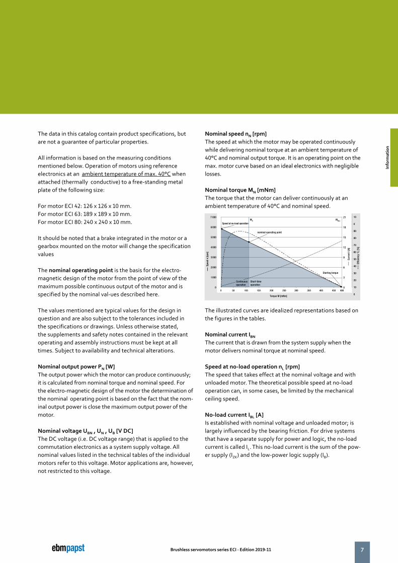
Nominal speed nN [rpm] The speed at which the motor may be operated continuously while delivering nominal torque at an ambient temperature of 40°C and nominal output torque. It is an operating point on the max. motor curve based on an ideal electronics with negligible losses.
Nominal torque MN [mNm] The torque that the motor can deliver continuously at an ambient temperature of 40°C and nominal speed.
The illustrated curves are idealized representations based on the figures in the tables.
Nominal current IBN The current that is drawn from the system supply when the motor delivers nominal torque at nominal speed.
Speed at no-load operation nL [rpm] The speed that takes effect at the nominal voltage and with unloaded motor. The theoretical possible speed at no-load operation can, in some cases, be limited by the mechanical ceiling speed.
No-load current IBL [A] Is established with nominal voltage and unloaded motor; is largely influenced by the bearing friction. For drive systems that have a separate supply for power and logic, the no-load current is called IL. This no-load current is the sum of the pow-er supply (IZK) and the low-power logic supply (IB).
0 50 100 150
Torque M [mNm]
Spee
d n
[rpm
]
200 250 300
7 000
6 000
5 000
4 000
3 000
2 000
1 000
0350 400 450 480
Curr
ent I
[A]
Short-time operation
MN MMax
Effic
ienc
y
[%
]
21
18
15
12
9
6
3
0
10
0
90
80
70
60
50
40
30
20
10
0
Continuousoperation
Speed at no-load operation
nominal operating point
Starting torque
Info
rmat
ion
Info
rmat
ion
8 Brushless servomotors series ECI · Edition 2019-11
Definitions for ECI Servomotors
Permanent stall torque MBn0 [mNm] Is the maximum permissible torque with which the motor may be permanently loaded when the rotor is locked.
Permissible eff. continuous stall current InOeff [A] Is the maximum permissible current which at a stalled motor is allowed to flow into the motor lead as an effective value.
Continuous stall power PBn0 [W] Is an approximate value for the voltage-independent maxi-mum permitted output (P=U x I) that can be taken from the DC voltage source in holding status.
Permissible peak torque short-term Mmax [mNm] Is the torque which the motor can usually deliver for a short time. (MA)
Permissible peak current, motor lead Imax [A] Is the current that must flow in to the motor lead as a peak value to achieve the short-time peak torque.
Induced voltage Uimax [V/1 000 rpm]Maximum value of the induced voltage between two motor leads at 1 000 rpm. It is a dimension for the electromagnetic utilization of the motor.
Connection resistance Rv [Ohm] The winding resistance that is measured at 20°C between any two of three winding terminations.
Connection inductance LV [mH]The average inductance that is measured at 20°C between any two of three winding terminations using a sinusoidal wave measuring frequency of 1 kHz.
Rotor moment of inertia JR [kgm2x10-6] The mass moment of inertia of the rotor and necessary dimension for the dynamic characteristics of the motor.
Protection class Information on the protection class; it describes protection against foreign particles (Point 1) and water (Point 2).
Permissible ambient temperature range TU [°C] Defines the minimum and maximum permissible ambient tempera-ture to which the mentioned performance values apply when the motor is in operation. The permissible winding temperature in the motor (115°C for insulation Class E, as per EN 60 034-1) </1125 should not be exceeded.
Weight m [kg] Weight of the delivered unit without additional units or packaging.
Max. shaft load Fradial/Faxial [N] The permissible forces are divided into radial and axial load values. They are based on the maximum permissible values for the motor bearing during operation at normal rating and a defined service life expectancy L10.
Service life L10 The values for the L10 service life specified in conjunction with the permitted bearing loads have been calculated to DIN ISO 281. In addition to the specified values, this calculation is based on operation of the motor at nominal conditions (nominal torque, nominal speed) and an ambient temperature of max. 40°C. Therefore, the service life information is explicitly not a guarantee of service life, but strictly a theoretical quality figure.
Max. reverse voltage [V DC] When the braking function is activated and when the set value step change is negative, the motor operates in controlled braking mode. In this operating state, the large part of the braking energy is fed back to the intermediate circuit until the max. reverse voltage is reached and the electronics prevent a further increase beyond this value by chopped braking. This behavior should be given special consideration when selecting the system supply.
Info
rmat
ion
Info
rmat
ion
9Brushless servomotors series ECI · Edition 2019-11
Set value input Speed setting via an analogue interface for DC voltage. Depending on the drive design, the set speed can be configured in a range from 0 ... nmax, where the minimum possible speed value (with limited control quality) is about 0 rpm (sine commutation) or approx. 50 to 100 rpm (block commutation). (Relevant only for drives with integrated operating electronics).
Recommended speed range [rpm] Speed control range within which the speed control accuracy stipulated in the system specification is complied with.
Starting torque [mNm] Is the torque that can be delivered over a short time when the motor is started based on the electromagnetic motor characteristics and the set current limitation.
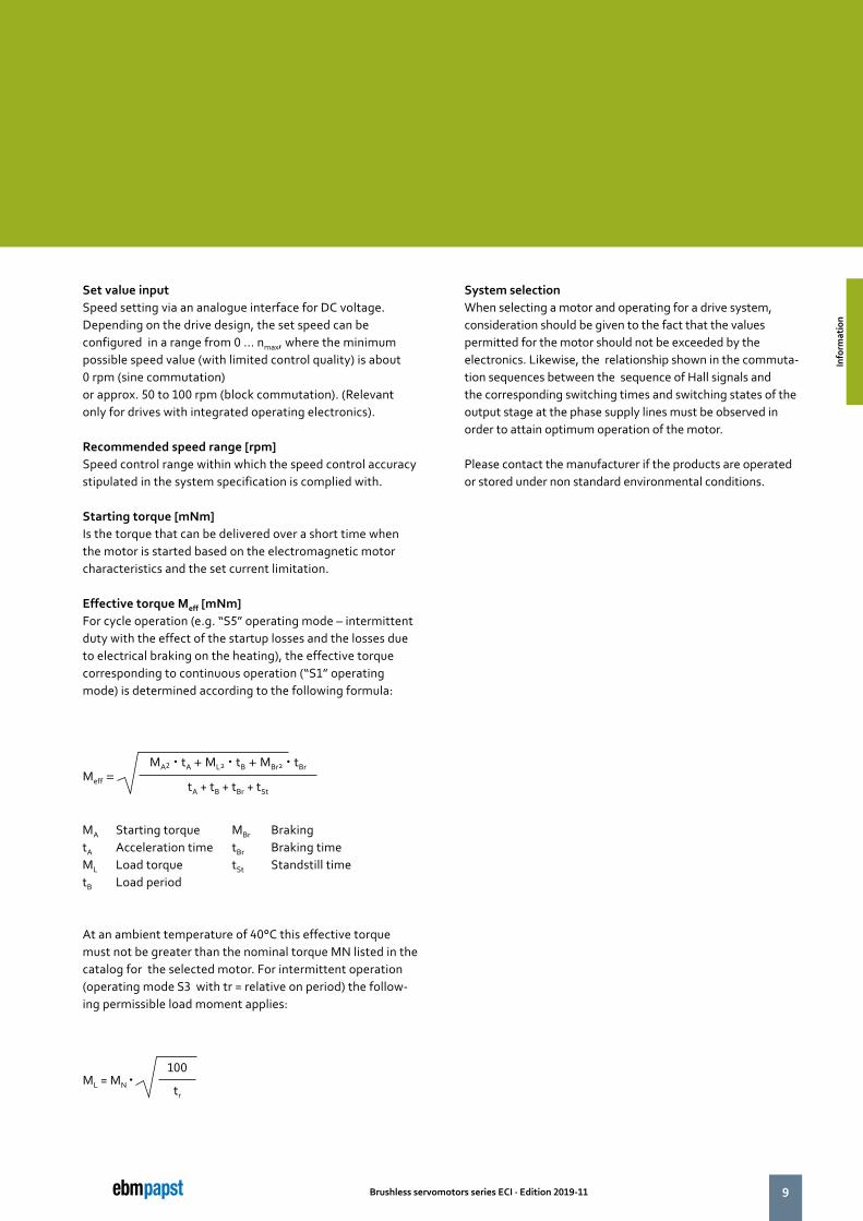
Effective torque Meff [mNm] For cycle operation (e.g. “S5” operating mode – intermittent duty with the effect of the startup losses and the losses due to electrical braking on the heating), the effective torque corresponding to continuous operation (“S1” operating mode) is determined according to the following formula:
At an ambient temperature of 40°C this effective torque must not be greater than the nominal torque MN listed in the catalog for the selected motor. For intermittent operation (operating mode S3 with tr = relative on period) the follow-ing permissible load moment applies:
MA Starting torque MBr BrakingtA Acceleration time tBr Braking timeML Load torque tSt Standstill timetB Load period
Meff = MA2 � tA + ML2 � tB + MBr2 � tBr
tA + tB + tBr + tSt
System selection When selecting a motor and operating for a drive system, consideration should be given to the fact that the values permitted for the motor should not be exceeded by the electronics. Likewise, the relationship shown in the commuta-tion sequences between the sequence of Hall signals and the corresponding switching times and switching states of the output stage at the phase supply lines must be observed in order to attain optimum operation of the motor.
Please contact the manufacturer if the products are operated or stored under non standard environmental conditions.
ML = MN �100
tr
Info
rmat
ion
Info
rmat
ion
10 Brushless servomotors series ECI · Edition 2019-11
GEAR
MOTOR
BRAKE & ENCODER
ELECTRONIC
EXTERNAL MODULE
ELECTRONIC-INTERFACE
10
11Brushless servomotors series ECI · Edition 2019-11
Brushless ServomotorsECI
ECI-
42.2
0-K
1 (p
. 14)
ECI-
42.4
0-K
1 (p
. 14)
ECI-
63.2
0-K
1 (p
. 16)
ECI-
63.4
0-K
1 (p
. 16)
ECI-
63.6
0-K
1 (p
. 16)
ECI-
63.2
0-K
3/4
/5 (p
. 22)
ECI-
63.4
0-K
3/4
/5 (p
. 22)
ECI-
63.6
0-K
3/4
/5 (p
. 22)
ECI-
80.2
0-K
1 (p
. 34)
ECI-
80.4
0-K
1 (p
. 34)
ECI-
80.6
0-K
1 (p
. 34)
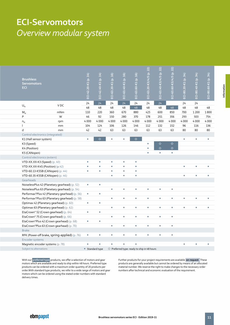
UN V DC24 24 24 24 24 24 24 24 2448 48 48 48 48 48 48 48 48 48 48
MN mNm 110 220 360 670 880 425 600 850 700 1 200 1 800P W 46 92 150 280 370 178 251 356 293 503 754nN rpm 4 000 4 000 4 000 4 000 4 000 4 000 4 000 4 000 4 000 4 000 4 000l mm 104 124 106 126 146 112 132 152 96 116 136d mm 42 42 63 63 63 63 63 63 80 80 80Control electronics (integrated) K1 (Hall sensor system) � � � � � � � �
K3 (Speed) � � �
K4 (Position) � � �
K5 (CANopen) � � �
Control electronics (extern) VTD-XX.XX-K3 (Speed) (p. 40) � � � � �
VTD-XX.XX-K4S (Position) (p.42) � � � � � � � �
VTD-60.13-K5SB (CANopen) (p. 44) � � � � �
VTD-60.35-K5SB (CANopen) (p. 46) � � � � � �
Gearheads NoiselessPlus 42 (Planetary gearhead) (p. 52) � �
NoiselessPlus 63 (Planetary gearhead) (p. 54) � � � � � �
Performax®Plus 42 (Planetary gearhead) (p. 56) � �
Performax®Plus 63 (Planetary gearhead) (p. 58) � � � � � � � � �
Optimax 42 (Planetary gearhead) (p. 60) � �
Optimax 63 (Planetary gearhead) (p. 62) � � � � � � � � �
EtaCrown® 52 (Crown gearhead) (p. 64) � �
EtaCrown® 75 (Crown gearhead) (p. 66) � � � � � �
EtaCrown®Plus 42 (Crown gearhead) (p. 68) � �
EtaCrown®Plus 63 (Crown gearhead) (p. 70) � � � � � �
Brake
RFK (Power-off brake, spring-applied) (p. 76) � � � � � � � �
Encoder systems Magnetic encoder systems (p. 78) � � � � � � � �
Subject to alternations � Standard type � Preferred type: ready to ship in 48 hours
With our preferred type products, we offer a selection of motors and gear motors which are available and ready to ship within 48 hours. Preferred type products can be ordered with a maximum order quantity of 20 products per order.With standard type products, we refer to a wide range of motors and gear motors which can be ordered using the stated order numbers with standard delivery times.
Further products for your project requirements are available on request. These products are generally available but cannot be ordered by means of an allocated material number. We reserve the right to make changes to the necessary order numbers after technical and economic evaluation of the requirement.
ECI-Servomotors Overview modular system
Info
rmat
ion
Info
rmat
ion
12 Brushless servomotors series ECI · Edition 2019-11
the engineer’s choice
13Brushless servomotors series ECI · Edition 2019-11
Page
ECI-42.XX-K1 14
ECI-63.XX-K1 18
ECI-63.XX-K3 22
ECI-63.XX-K4 26
ECI-63.XX-K5 30
ECI-80.XX-K1 34
Servomtors ECI
ECI-S
ervo
mot
ors
ECI-S
ervo
mot
ors
14 Brushless servomotors series ECI · Edition 2019-11
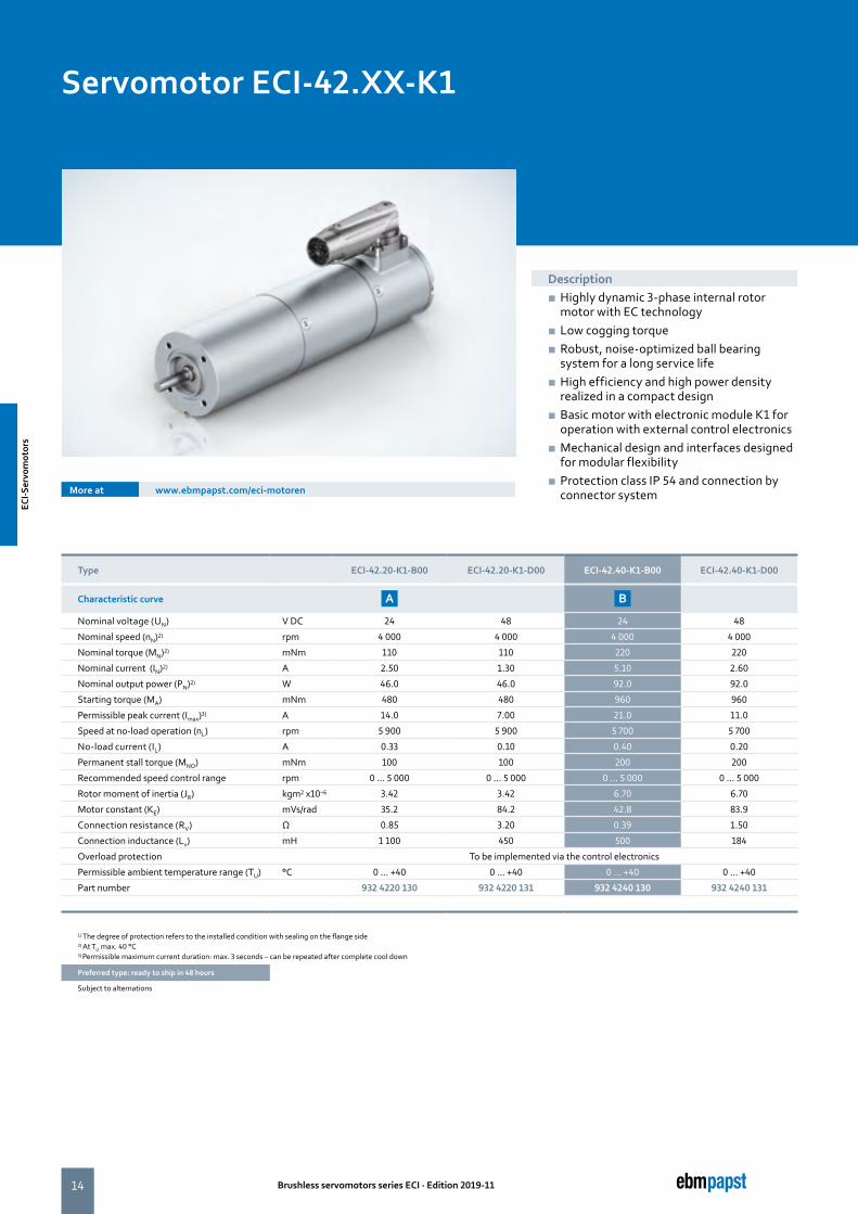
Type ECI-42.20-K1-B00 ECI-42.20-K1-D00 ECI-42.40-K1-B00 ECI-42.40-K1-D00
Characteristic curve A B
Nominal voltage (UN) V DC 24 48 24 48
Nominal speed (nN)2) rpm 4 000 4 000 4 000 4 000
Nominal torque (MN)2) mNm 110 110 220 220
Nominal current (IN)2) A 2.50 1.30 5.10 2.60
Nominal output power (PN)2) W 46.0 46.0 92.0 92.0
Starting torque (MA) mNm 480 480 960 960
Permissible peak current (Imax)3) A 14.0 7.00 21.0 11.0
Speed at no-load operation (nL) rpm 5 900 5 900 5 700 5 700
No-load current (IL) A 0.33 0.10 0.40 0.20
Permanent stall torque (MNO) mNm 100 100 200 200
Recommended speed control range rpm 0 ... 5 000 0 ... 5 000 0 ... 5 000 0 ... 5 000
Rotor moment of inertia (JR) kgm2 x10–6 3.42 3.42 6.70 6.70
Motor constant (KE) mVs/rad 35.2 84.2 42.8 83.9
Connection resistance (RV) Ω 0.85 3.20 0.39 1.50
Connection inductance (Lv) mH 1 100 450 500 184
Overload protection To be implemented via the control electronics
Permissible ambient temperature range (TU) °C 0 ... +40 0 ... +40 0 ... +40 0 ... +40
Part number 932 4220 130 932 4220 131 932 4240 130 932 4240 131
1) The degree of protection refers to the installed condition with sealing on the flange side2) At TU max. 40 °C3) Permissible maximum current duration: max. 3 seconds – can be repeated after complete cool down
Preferred type: ready to ship in 48 hours
Subject to alternations
More at www.ebmpapst.com/eci-motoren
Description ■ Highly dynamic 3-phase internal rotor motor with EC technology
■ Low cogging torque ■ Robust, noise-optimized ball bearing system for a long service life
■ High efficiency and high power density realized in a compact design
■ Basic motor with electronic module K1 for operation with external control electronics
■ Mechanical design and interfaces designed for modular flexibility
■ Protection class IP 54 and connection by connector system
Servomotor ECI-42.XX-K1
ECI-S
ervo
mot
ors
ECI-S
ervo
mot
ors
15Brushless servomotors series ECI · Edition 2019-11
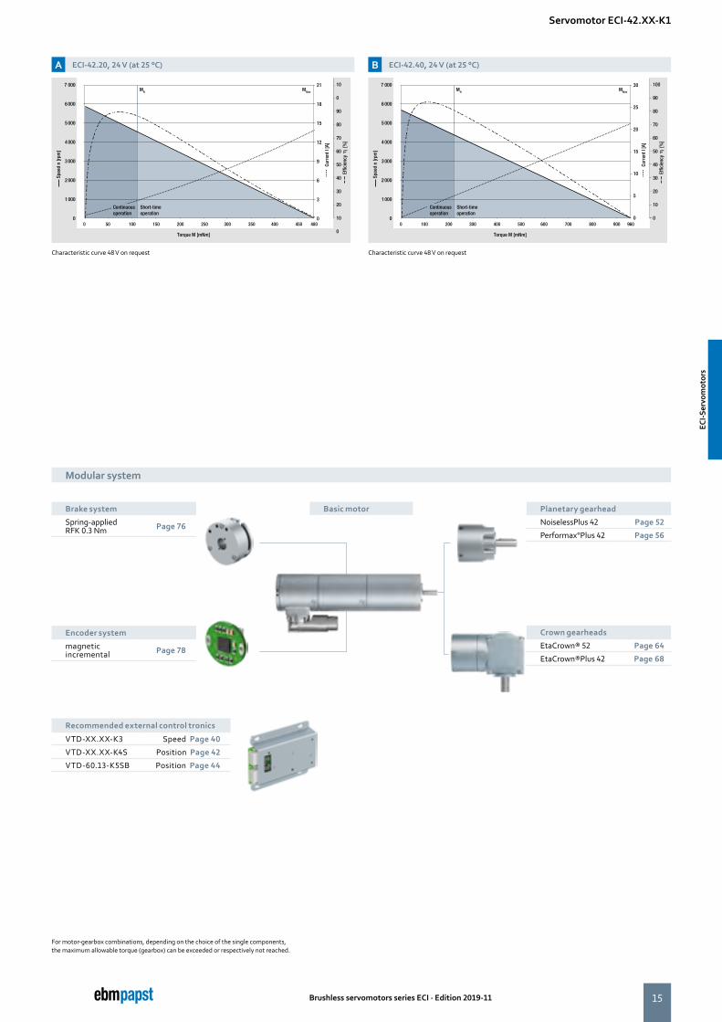
A ECI-42.20, 24 V (at 25 °C) B ECI-42.40, 24 V (at 25 °C)
Characteristic curve 48 V on request Characteristic curve 48 V on request
Servomotor ECI-42.XX-K1
0 50 100 150
Torque M [mNm]
Spee
d n
[rpm
]
200 250 300
7 000
6 000
5 000
4 000
3 000
2 000
1 000
0350 400 450 480
Curr
ent I
[A]
Short-time operation
MN MMax
Effic
ienc
y
[%
]
21
18
15
12
9
6
3
0
10
0
90
80
70
60
50
40
30
20
10
0
Continuousoperation
0 100 200 300 400 500 600
7 000
6 000
5 000
4 000
3 000
2 000
1 000
0700 800 900 960
MN MMax
30
25
20
15
10
5
0
100
90
80
70
60
50
40
30
20
10
0
Torque M [mNm]
Spee
d n
[rpm
]
Curr
ent I
[A]
Short-time operation
Effic
ienc
y
[%
]
Continuousoperation
Modular system
Basic motor
For motor-gearbox combinations, depending on the choice of the single components,the maximum allowable torque (gearbox) can be exceeded or respectively not reached.
Brake system
Spring-appliedRFK 0.3 Nm Page 76
Planetary gearhead
NoiselessPlus 42 Page 52
Performax®Plus 42 Page 56
Encoder system
magnetic incremental Page 78
Recommended external control tronics
VTD-XX.XX-K3 Speed Page 40
VTD-XX.XX-K4S Position Page 42
VTD-60.13-K5SB Position Page 44
Crown gearheads
EtaCrown® 52 Page 64
EtaCrown®Plus 42 Page 68
ECI-S
ervo
mot
ors
ECI-S
ervo
mot
ors
16
B
4
5
2
3
6
7
1
A
10
9
8
C
11
12
Ø 2
2 -0
,03Ø
5 g5
Ø 3
2
Ø 4
2 ±0
,2
L
1
2 ±0,1
18,5 ±0,3
66
4x90
°
45
Ø 2
2 -0
,03Ø
5 g5
Ø 3
2
Ø 4
2 ±0
,2
L
1
2 ±0,1
18,5 ±0,3
66
4x90
°
45
Brushless servomotors series ECI · Edition 2019-11
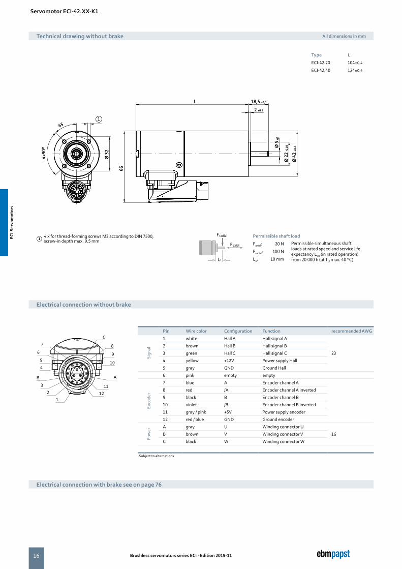
Servomotor ECI-42.XX-K1
Type L
ECI-42.20 104±0.4
ECI-42.40 124±0.4
Technical drawing without brake All dimensions in mm
① 4 x for thread-forming screws M3 according to DIN 7500, screw-in depth max. 9.5 mm
Faxial
Fradial
L1
Permissible shaft load
Faxial: 20 N Permissible simultaneous shaft loads at rated speed and service life expectancy L10 (in rated operation) from 20 000 h (at TU max. 40 °C)
Fradial: 100 N
L1: 10 mm
Electrical connection without brake
Pin Wire color Configuration Function recommended AWG
Sign
al
1 white Hall A Hall signal A
23
2 brown Hall B Hall signal B
3 green Hall C Hall signal C
4 yellow +12V Power supply Hall
5 gray GND Ground Hall
6 pink empty empty
Enco
der
7 blue A Encoder channel A
8 red /A Encoder channel A inverted
9 black B Encoder channel B
10 violet /B Encoder channel B inverted
11 gray / pink +5V Power supply encoder
12 red / blue GND Ground encoder
Pow
er
A gray U Winding connector U
16B brown V Winding connector V
C black W Winding connector W
Subject to alternations
Electrical connection with brake see on page 76
ECI-S
ervo
mot
ors
ECI-S
ervo
mot
ors
17
LL
Brushless servomotors series ECI · Edition 2019-11
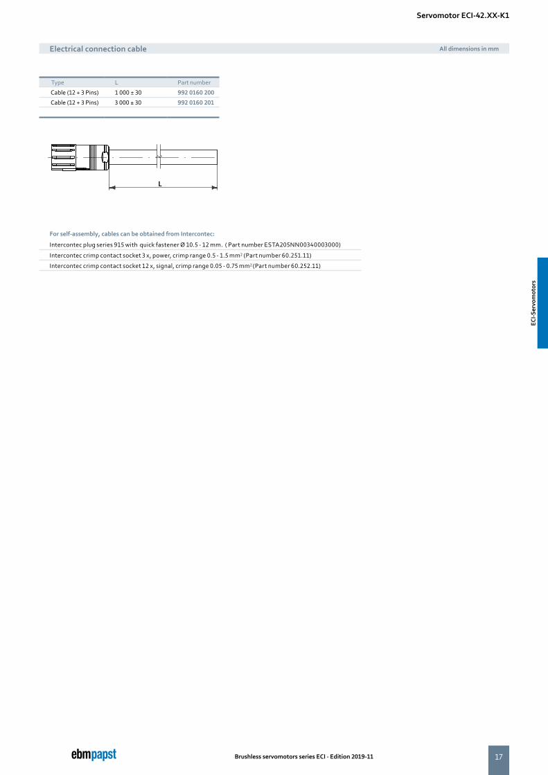
Servomotor ECI-42.XX-K1
Type L Part number
Cable (12 + 3 Pins) 1 000 ± 30 992 0160 200
Cable (12 + 3 Pins) 3 000 ± 30 992 0160 201
Electrical connection cable All dimensions in mm
For self-assembly, cables can be obtained from Intercontec:
Intercontec plug series 915 with quick fastener Ø 10.5 - 12 mm. ( Part number ESTA205NN00340003000)
Intercontec crimp contact socket 3 x, power, crimp range 0.5 - 1.5 mm2 (Part number 60.251.11)
Intercontec crimp contact socket 12 x, signal, crimp range 0.05 - 0.75 mm2 (Part number 60.252.11)
ECI-S
ervo
mot
ors
ECI-S
ervo
mot
ors

18 Brushless servomotors series ECI · Edition 2019-11
Servomotor ECI-63.XX-K1
Type ECI-63.20-K1 -B00
ECI-63.20-K1 -D00
ECI-63.40-K1 -B00
ECI-63.40-K1 -D00
ECI-63.60-K1 -B00
ECI-63.60-K1 -D00
Characteristic curve A B C
Nominal voltage (UN) V DC 24 48 24 48 24 48
Nominal speed (nN)2) rpm 4 000 4 000 4 000 4 000 4 000 4 000
Nominal torque (MN)2) mNm 360 360 670 670 800 880
Nominal current (IN)2) A 8.50 4.50 14.0 6.50 17.6 8.50
Nominal output power (PN)2) W 150 150 280 280 335 370
Starting torque (MA) mNm 1 800 1 800 3 300 3 300 5 300 4 400
Permissible peak current (Imax)3) A 55 30 95 45 150 57
Speed at no-load operation (nL) rpm 5 800 6 800 5 900 5 900 6 100 6 000
No-load current (IL) A 0.50 0.30 0.70 0.32 1.30 0.45
Recommended speed control range rpm 0 ... 5 000 0 ... 5 000 0 ... 5 000 0 ... 5 000 0 ... 5 000 0 ... 5 000
Rotor moment of inertia (JR) kgm2 x10–6 19.0 19.0 38.0 38.0 57.0 57.0
Motor constant (KE) mVs/rad 41.4 73.3 40.4 83.8 40.4 83.8
Connection resistance (RV) Ω 0.14 0.42 0.08 0.24 0.04 0.15
Connection inductance (LV) mH 260 880 140 570 90.0 330
Overload protection To be implemented via the control electronics
Permissible ambient temperature range (TU) °C 0 ... +40 0 ... +40 0 ... +40 0 ... +40 0 ... +40 0 ... +40
Weight kg 0.90 0.90 1.20 1.20 1.50 1.50
Part number (wire interface) 1) IP 40 932 6320 103 932 6320 105 932 6340 103 932 6340 105 932 6360 106 932 6360 108
Part number (connector interface) 1) IP 54 on request on request on request on request on request on request
1) The degree of protection refers to the installed condition with sealing on the flange side The shaft geometry in the IP54 version is different from the displayed sketch2) At TU max. 40 °C3) Permissible maximum current duration: max. 1 seconds – can be repeated after complete cool down
Preferred type: ready to ship in 48 hours
Subject to alternations
More at www.ebmpapst.com/eci-motoren
Description ■ Highly dynamic 3-phase internal rotor motor with EC technology
■ Low cogging torque ■ Robust, noise-optimized ball bearing system for a longservice life
■ High efficiency and high power density realized in a compact design
■ Basic motor with electronic module K1 for operation with external control electronics
■ Mechanical design and interfaces designed for modular flexibility
■ Protection class IP 40 / IP 54 and connection by connector system
ECI-S
ervo
mot
ors
ECI-S
ervo
mot
ors
19Brushless servomotors series ECI · Edition 2019-11
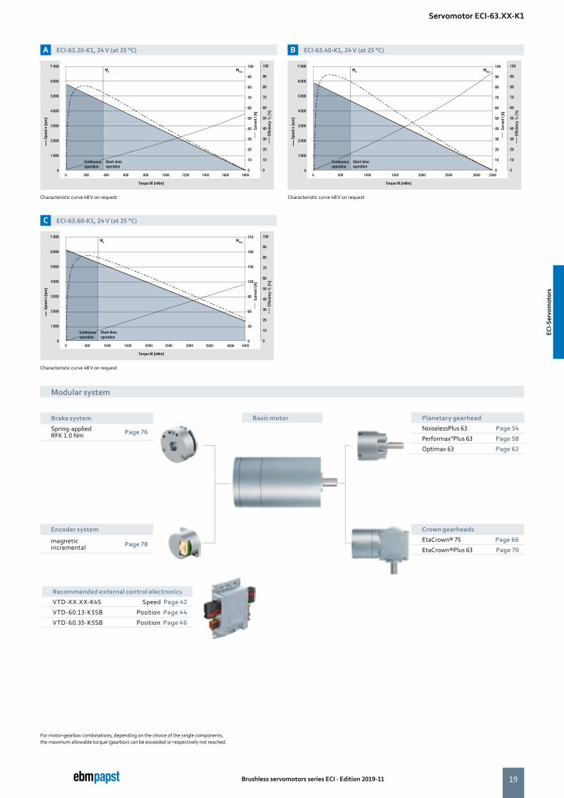
A ECI-63.20-K1, 24 V (at 25 °C)
C ECI-63.60-K1, 24 V (at 25 °C)
B ECI-63.40-K1, 24 V (at 25 °C)
Characteristic curve 48 V on request
Characteristic curve 48 V on request
Characteristic curve 48 V on request
0 200 400 600 800 1000 1200
7 000
6 000
5 000
4 000
3 000
2 000
1 000
01400 1600 1800
MN MMax
100
90
80
70
60
50
40
30
20
10
0
100
90
80
70
60
50
40
30
20
10
0
Torque M [mNm]
Spee
d n
[rpm
]
Curr
ent I
[A]
Short-time operation
Effic
ienc
y
[%
]
Continuousoperation
0 500 1000 1500 2000 2500 400035003000
7 000
6 000
5 000
4 000
3 000
2 000
1 000
04400
MN MMax
210
180
150
120
90
60
30
0
100
90
80
70
60
50
40
30
20
10
0
Torque M [mNm]
Spee
d n
[rpm
]
Curr
ent I
[A]
Short-time operation
Effic
ienc
y
[%
]
Continuousoperation
0 500 1000 1500 2000 2500 3000
7 000
6 000
5 000
4 000
3 000
2 000
1 000
03300
MN MMax
100
90
80
70
60
50
40
30
20
10
0
100
90
80
70
60
50
40
30
20
10
0
Torque M [mNm]
Spee
d n
[rpm
]
Curr
ent I
[A]
Short-time operation
Effic
ienc
y
[%
]
Continuousoperation
For motor-gearbox combinations, depending on the choice of the single components, the maximum allowable torque (gearbox) can be exceeded or respectively not reached.
Modular system
Basic motorBrake system
Spring-appliedRFK 1.0 Nm Page 76
Encoder system
magnetic incremental Page 78
Modular system
Servomotor ECI-63.XX-K1
Crown gearheads
EtaCrown® 75 Page 66
EtaCrown®Plus 63 Page 70
Planetary gearhead
NoiselessPlus 63 Page 54
Performax®Plus 63 Page 58
Optimax 63 Page 62
Recommended external control electronics
VTD-XX.XX-K4S Speed Page 42
VTD-60.13-K5SB Position Page 44
VTD-60.35-K5SB Position Page 46
63.2
0_
ECI-S
ervo
mot
ors
ECI-S
ervo
mot
ors
20
4 x
90°
4 x
90°
30°
35°
10±
1
4 x 9
0°
Ø D
Ø 25
40,0-
Ø 63
2,0±
Ø 6g
5
14±0,7
Ø 49
Ø 40
Ø 36
500±
10
3 x 12
0°
Ø 19
,05
L1 20±0,3
2±0,1
5
2
1
34
6
500±
10
10±
1
②①③
500±
10
10±
1
②①③
4 x
90°
4 x
90°
30°
35°
10±
1
4 x 9
0°
Ø D
Ø 25
40,0-
Ø 63
2,0±
Ø 6g
5
14±0,7
Ø 49
Ø 40
Ø 36
500±
10
3 x 12
0°
Ø 19
,05
L1 20±0,3
2±0,1
5
2
1
34
6
500±
10
10±
1
②①③
500±
10
10±
1
②①③
Brushless servomotors series ECI · Edition 2019-11
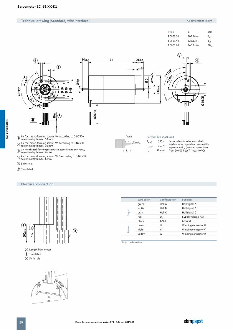
Servomotor ECI-63.XX-K1
Type L ØD
ECI-63.20 106.1±0.4 6g5
ECI-63.40 126.1±0.4 6g5
ECI-63.60 146.1±0.4 10g5
① 8 x for thread-forming screws M4 according to DIN7500, screw-in depth max. 10 mm
② 4 x for thread-forming screws M5 according to DIN7500, screw-in depth max. 10 mm
③ 3 x For thread-forming screws M3 according to DIN7500, screw-in depth max. 6 mm
④ 4 x for thread-forming screws M2,5 according to DIN7500, screw-in depth max. 6 mm
⑤ 5x ferrule
⑥ Tin-plated
Faxial
Fradial
L1
Permissible shaft load
Faxial: 150 N Permissible simultaneous shaft loads at rated speed and service life expectancy L10 (in rated operation) from 20 000 h (at TU max. 40 °C)
Fradial: 150 N
L1: 20 mm
Technical drawing (Standard, wire interface) All dimensions in mm
Electrical connection
Wire color Configuration Funkion
Sign
al
green Hall A Hall signal A
white Hall B Hall signal B
gray Hall C Hall signal C
red UB Supply voltage Hall
black GND Ground
Pow
er
brown U Winding connector U
violet V Winding connector V
yellow W Winding connector W
Subject to alternations
① Length from motor
② Tin-plated
③ 5x ferrule
ECI-S
ervo
mot
ors
ECI-S
ervo
mot
ors
21
500±
10 4±0,
5① ②
500±
10 4±0,
5① ②
500±
10 4±0,
5① ②
500±
10 4±0,
5① ②
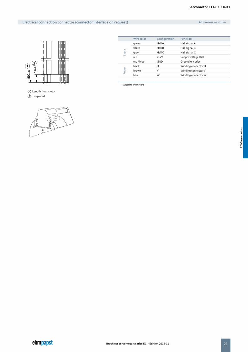
Brushless servomotors series ECI · Edition 2019-11
Wire color Configuration Function
Sign
al
green Hall A Hall signal A
white Hall B Hall signal B
gray Hall C Hall signal C
red +12V Supply voltage Hall
red / blue GND Ground encoder
Pow
er
black U Winding connector U
brown V Winding connector V
blue W Winding connector W
Subject to alternations
Electrical connection connector (connector interface on request) All dimensions in mm
Servomotor ECI-63.XX-K1
① Length from motor
② Tin-plated
ECI-S
ervo
mot
ors
ECI-S
ervo
mot
ors
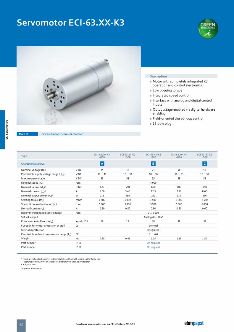
22 Brushless servomotors series ECI · Edition 2019-11
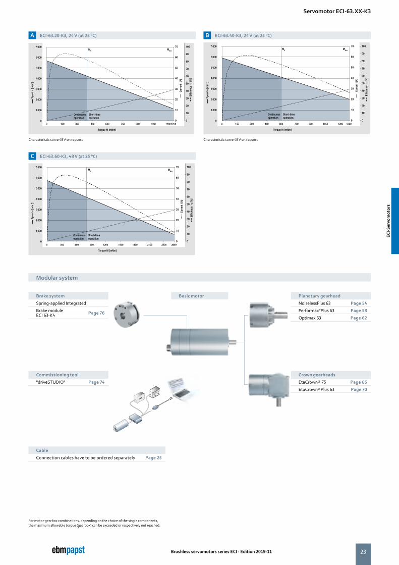
Servomotor ECI-63.XX-K3
Type ECI-63.20-K3 -B00
ECI-63.20-K3 -D00
ECI-63.40-K3-B00
ECI-63.40-K3-D00
ECI-63.60-K3 -D00
Characteristic curve A B C
Nominal voltage (UN) V DC 24 48 24 48 48
Permissible supply voltage range (UZK) V DC 18 ... 30 18 ... 53 18 ... 30 18 ... 53 18 ... 53
Max. reverse voltage V DC 35 58 35 58 58
Nominal speed (nN) rpm 4 000
Nominal torque (MN)2) mNm 425 450 600 600 850
Nominal current (IN)2) A 8.50 5.40 12.3 7.20 8.60
Nominal output power (PN)2) W 178 188 251 314 356
Starting torque (MA) mNm 1 480 1 890 1 500 3 000 2 550
Speed at no-load operation (nL) rpm 5 800 5 800 5 900 5 800 6 000
No-load current (IL) A 0.50 0.50 0.90 0.50 0.60
Recommended speed control range rpm 0 ... 5 000
Set value input Analog (0 ... 10V)
Rotor moment of inertia (JR) kgm2 x10–6 19 19 38 38 57
Function for motor protection at stall Ω thermal
Overload protection Integrated
Permissible ambient temperature range (TU) °C 0 ... +40
Weight kg 0.85 0.85 1.15 1.15 1.50
Part number IP 40 On request
Part number IP 54 On request
1) The degree of protection refers to the installed condition with sealing on the flange side The shaft geometry in the IP54 version is different from the displayed sketch2) At TU max. 40 °C
Subject to alternations
Description ■ Motor with completely integrated K3 operation and control electronics
■ Low cogging torque ■ Integrated speed control ■ Interface with analog and digital control inputs
■ Output stage enabled via digital hardware enabling
■ Field-oriented closed-loop control ■ 15-pole plug
More at www.ebmpapst.com/eci-motoren
ECI-S
ervo
mot
ors
ECI-S
ervo
mot
ors
23Brushless servomotors series ECI · Edition 2019-11
0 150 300 450 600 750 12001050900
7 000
6 000
5 000
4 000
3 000
2 000
1 000
01250
MN MMax
70
60
50
40
30
20
10
0
100
90
80
70
60
50
40
30
20
10
0
Torque M [mNm]
Spee
d n
[min
-1]
Curr
ent I
[A]
Short-time operation
Effic
ienc
y
[%
]
Continuousoperation
7 000
6 000
5 000
4 000
3 000
2 000
1 000
0
MN MMax
70
60
50
40
30
20
10
00 300 600 900 1200 1500 1800 2100 2400 2600
100
90
80
70
60
50
40
30
20
10
0
Torque M [mNm]
Spee
d n
[min
-1]
Curr
ent I
[A]
Short-time operation
Effic
ienc
y
[%
]
Continuousoperation
7 000
6 000
5 000
4 000
3 000
2 000
1 000
0
MN MMax
70
60
50
40
30
20
10
00 150 300 450 600 750 900 1050 1200 1300
100
90
80
70
60
50
40
30
20
10
0
Torque M [mNm]
Spee
d n
[min
-1]
Curr
ent I
[A]
Short-time operation
Effic
ienc
y
[%
]
Continuousoperation
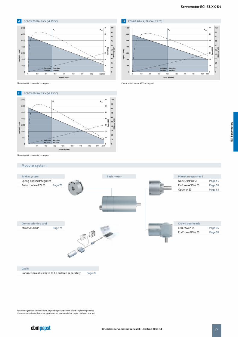
A ECI-63.20-K3, 24 V (at 25 °C)
C ECI-63.60-K3, 48 V (at 25 °C)
B ECI-63.40-K3, 24 V (at 25 °C)
Characteristic curve 48 V on request Characteristic curve 48 V on request
For motor-gearbox combinations, depending on the choice of the single components, the maximum allowable torque (gearbox) can be exceeded or respectively not reached.
Modular system
Basic motorBrake system
Spring-applied Integrated
Brake module ECI 63-K4 Page 76
Planetary gearhead
NoiselessPlus 63 Page 54
Performax®Plus 63 Page 58
Optimax 63 Page 62
Modular system
Servomotor ECI-63.XX-K3
Cable
Connection cables have to be ordered separately Page 25
Crown gearheads
EtaCrown® 75 Page 66
EtaCrown®Plus 63 Page 70
Commissioning tool
"driveSTUDIO" Page 74EC
I-Ser
vom
otor
s
ECI-S
ervo
mot
ors
24
12
7
11
8
10
9
3
BAC
4
2
5
1
6
5,8
Ø 63
,5
4 x 90°
30°
4 x 90
°
Ø 63
±0,
2R
20,25
±0,1
(16,3)
Ø 49
Ø 40
Ø 36
L
Ø 25
-0,
04
20±0,3
ØD
2±0,1
M16
3
1
2
5,8
Ø 63
,5
4 x 90°
30°
4 x 90
°
Ø 63
±0,
2R
20,25
±0,1
(16,3)
Ø 49
Ø 40
Ø 36
L
Ø 25
-0,
04
20±0,3
ØD
2±0,1
M16
3
1
2
Brushless servomotors series ECI · Edition 2019-11
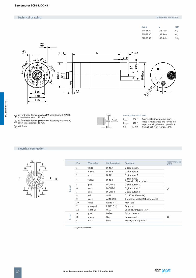
Pin Wire color Configuration Function recommended AWG
Sig
nal
1 white D-IN-A Digital input A
24
2 brown D-IN-B Digital input B
3 green D-IN-1 Digital input 1
4 yellow D-IN-2 Digital input 2 Analog 0 ... 10 V / brake
5 gray D-OUT-1 Digital output 1
6 pink D-OUT-2 Digital output 2
7 blue D-OUT-3 Digital output 3
8 red A-IN-1 0 ... 10 V (differential)
9 black A-IN-GND Ground for analog IN 1 (differential)
10 violet RS485 A (+) Prog.-bus
11 gray / pink RS485 B (–) Prog.-bus
12 red / blue ULogic Logic power supply (24 V)
Pow
er
A gray Ballast Ballast resistor
16B brown UZK Power supply
C black GND Power / signal ground
Subject to alternations
Servomotor ECI-63.XX-K3
① 4 x for thread-forming screws M5 according to DIN7500, screw-in depth max. 10 mm
② 8 x for thread-forming screws M4 according to DIN7500, screw-in depth max. 10 mm
③ M5, 5 mm
Faxial
Fradial
L1
Permissible shaft load
Faxial: 150 N Permissible simultaneous shaft loads at rated speed and service life expectancy L10 (in rated operation) from 20 000 h (at TU max. 40 °C)
Fradial: 150 N
L1: 20 mm
Technical drawing All dimensions in mm
Electrical connection
Type L ØD
ECI-63.20 118.5±0.4 6g5
ECI-63.40 138.5±0.4 6g5
ECI-63.60 158.5±0.4 10g5
ECI-S
ervo
mot
ors
ECI-S
ervo
mot
ors
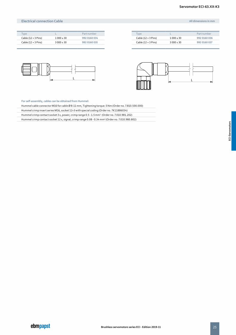
25Brushless servomotors series ECI · Edition 2019-11
Type L Part number
Cable (12 + 3 Pins) 1 000 ± 30 992 0160 034
Cable (12 + 3 Pins) 3 000 ± 30 992 0160 035
For self-assembly, cables can be obtained from Hummel:
Hummel cable connector M16 for cable Ø 8-11 mm, Tightening torque: 5 Nm (Order no. 7.810.500.000)
Hummel crimp insert series M16, socket 12+3 with special coding (Order no. 7K11886034)
Hummel crimp contact socket 3 x, power, crimp range 0.5 - 1.5 mm2 (Order no. 7.010.981.202)
Hummel crimp contact socket 12 x, signal, crimp range 0.08 - 0.34 mm2 (Order no. 7.010.980.802)
Electrical connection Cable All dimensions in mm
Servomotor ECI-63.XX-K3
Type L Part number
Cable (12 + 3 Pins) 1 000 ± 30 992 0160 036
Cable (12 + 3 Pins) 3 000 ± 30 992 0160 037
ECI-S
ervo
mot
ors
ECI-S
ervo
mot
ors
26 Brushless servomotors series ECI · Edition 2019-11
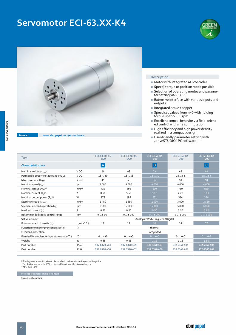
Servomotor ECI-63.XX-K4
Type ECI-63.20-K4 -B00
ECI-63.20-K4 -D00
ECI-63.40-K4-B00
ECI-63.40-K4-D00
ECI-63.60-K4 -D00
Characteristic curve A B C
Nominal voltage (UN) V DC 24 48 24 48 48
Permissible supply voltage range (UZK) V DC 18 ... 30 18 ... 53 18 ... 30 18 ... 53 18 ... 53
Max. reverse voltage V DC 35 58 35 58 58
Nominal speed (nN) rpm 4 000 4 000 4 000 4 000 4 000
Nominal torque (MN)2) mNm 425 450 600 750 850
Nominal current (IN)2) A 8.50 5.40 12.3 7.20 8.60
Nominal output power (PN)2) W 178 188 251 314 356
Starting torque (Mmax) mNm 1 480 1 890 1 500 3 000 2 550
Speed at no-load operation (nL) rpm 5 800 5 800 5 900 5 800 6 000
No-load current (IL) A 0.50 0.50 0.90 0.50 0.60
Recommended speed control range rpm 0 ... 5 000 0 ... 5 000 0 ... 5 000 0 ... 5 000 0 ... 5 000
Set value input Analog / PWM / Freguenz / Digital
Rotor moment of inertia (JR) kgm2 x10–6 19 19 38 38 57
Function for motor protection at stall Ω thermal
Overload protection Integrated
Permissible ambient temperature range (TU) °C 0 ... +40 0 ... +40 0 ... +40 0 ... +40 0 ... +40
Weight kg 0.85 0.85 1.15 1.15 1.50
Part number IP 40 932 6320 403 932 6320 405 932 6340 403 932 6340 405 932 6360 405
Part number IP 54 932 6320 400 932 6320 402 932 6340 400 932 6340 402 932 6360 402
1) The degree of protection refers to the installed condition with sealing on the flange side The shaft geometry in the IP54 version is different from the displayed sketch2) At TU max. 40 °C
Preferred type: ready to ship in 48 hours
Subject to alternations
Description ■ Motor with integrated 4Q controler ■ Speed, torque or position mode possible ■ Selection of operating modes and parame-ter setting via RS485
■ Extensive interface with various inputs and outputs
■ Integrated brake chopper ■ Speed set values from n=0 with holding torque up to 5 000 rpm
■ Excellent control behavior via field-orient-ed control with sine commutation
■ High efficiency and high power density realized in a compact design
■ User-friendly parameter setting with „driveSTUDIO“ PC software
More at www.ebmpapst.com/eci-motoren
ECI-S
ervo
mot
ors
ECI-S
ervo
mot
ors
27Brushless servomotors series ECI · Edition 2019-11
A ECI-63.20-K4, 24 V (at 25 °C)
C ECI-63.60-K4, 24 V (at 25 °C)
B ECI-63.40-K4, 24 V (at 25 °C)
Characteristic curve 48 V on request
Characteristic curve 48 V on request
Characteristic curve 48 V on request
For motor-gearbox combinations, depending on the choice of the single components, the maximum allowable torque (gearbox) can be exceeded or respectively not reached.
Modular system
Basic motorBrake system
Spring-applied Integrated
Brake module ECI 63 Page 76
Planetary gearhead
NoiselessPlus 63 Page 54
Performax®Plus 63 Page 58
Optimax 63 Page 62
Modular system
Servomotor ECI-63.XX-K4
Crown gearheads
EtaCrown® 75 Page 66
EtaCrown®Plus 63 Page 70
Commissioning tool
"driveSTUDIO" Page 74
0 150 300 450 600 750 12001050900
7 000
6 000
5 000
4 000
3 000
2 000
1 000
01250
MN MMax
70
60
50
40
30
20
10
0
100
90
80
70
60
50
40
30
20
10
0
Torque M [mNm]
Spee
d n
[min
-1]
Curr
ent I
[A]
Short-time operation
Effic
ienc
y
[%
]
Continuousoperation
7 000
6 000
5 000
4 000
3 000
2 000
1 000
0
MN MMax
70
60
50
40
30
20
10
00 300 600 900 1200 1500 1800 2100 2400 2600
100
90
80
70
60
50
40
30
20
10
0
Torque M [mNm]
Spee
d n
[min
-1]
Curr
ent I
[A]
Short-time operation
Effic
ienc
y
[%
]
Continuousoperation
7 000
6 000
5 000
4 000
3 000
2 000
1 000
0
MN MMax
70
60
50
40
30
20
10
00 150 300 450 600 750 900 1050 1200 1300
100
90
80
70
60
50
40
30
20
10
0
Torque M [mNm]
Spee
d n
[min
-1]
Curr
ent I
[A]
Short-time operation
Effic
ienc
y
[%
]
Continuousoperation
Cable
Connection cables have to be ordered separately Page 29
ECI-S
ervo
mot
ors
ECI-S
ervo
mot
ors

28
12
7
11
8
10
9
3
BAC
4
2
5
1
6
5,8
Ø 63
,5
4 x 90°
30°
4 x 90
°
Ø 63
±0,
2R
20,25
±0,1
(16,3)
Ø 49
Ø 40
Ø 36
L
Ø 25
-0,
04
20±0,3
ØD
2±0,1
M16
3
1
2
5,8
Ø 63
,5
4 x 90°
30°
4 x 90
°
Ø 63
±0,
2R
20,25
±0,1
(16,3)
Ø 49
Ø 40
Ø 36
L
Ø 25
-0,
04
20±0,3
ØD
2±0,1
M16
3
1
2
Brushless servomotors series ECI · Edition 2019-11
Servomotor ECI-63.XX-K4
① 4 x for thread-forming screws M5 according to DIN7500, screw-in depth max. 10 mm
② 8 x for thread-forming screws M4 according to DIN7500, screw-in depth max. 10 mm
③ M5, 5 mm
Faxial
Fradial
L1
Permissible shaft load
Faxial: 150 N Permissible simultaneous shaft loads at rated speed and service life expectancy L10 (in rated operation) from 20 000 h (at TU max. 40 °C)
Fradial: 150 N
L1: 20 mm
Technical drawing All dimensions in mm
Electrical connection
Type L ØD
ECI-63.20 118.5±0.4 6g5
ECI-63.40 138.5±0.4 6g5
ECI-63.60 158.5±0.4 10g5
Pin Wire color Configuration Function recommended AWG
Sig
nal
1 white D-IN-A Digital input A
24
2 brown D-IN-B Digital input B
3 green D-IN-1 Digital input 1
4 yellow D-IN-2 Digital input 2 Analog 0 ... 10 V / brake
5 gray D-OUT-1 Digital output 1
6 pink D-OUT-2 Digital output 2
7 blue D-OUT-31) Digital output 3
8 red A-IN-1 0 ... 10 V (differential)
9 black A-IN-GND Ground for analog IN 1 for differential
10 violet RS485 A (+) Prog.-bus
11 gray / pink RS485 B (–) Prog.-bus
12 red / blue ULogic Logic power supply (24 V)
Pow
er
A gray Ballast Ballast resistor
16B brown UZK Power supply
C black GND Power- / signal-ground
1) Output (OUT 3) is only available on ECI-63.XX-K4Subject to alternations
ECI-S
ervo
mot
ors
ECI-S
ervo
mot
ors

29Brushless servomotors series ECI · Edition 2019-11
Electrical connection Cable All dimensions in mm
Servomotor ECI-63.XX-K4
Type L Part number
Cable (12 + 3 Pins) 1 000 ± 30 992 0160 034
Cable (12 + 3 Pins) 3 000 ± 30 992 0160 035
Type L Part number
Cable (12 + 3 Pins) 1 000 ± 30 992 0160 036
Cable (12 + 3 Pins) 3 000 ± 30 992 0160 037
For self-assembly, cables can be obtained from Hummel:
Hummel cable connector M16 for cable Ø 8-11 mm, Tightening torque: 5 Nm (Order no. 7.810.500.000
Hummel crimp insert series M16, socket 12+3 with special coding (Order no. 7K11886034)
Hummel crimp contact socket 3 x, power, crimp range 0.5 - 1.5 mm2 (Order no. 7.010.981.202)
Hummel crimp contact socket 12 x, signal, crimp range 0.08 - 0.34 mm2 (Order no. 7.010.980.802)
ECI-S
ervo
mot
ors
ECI-S
ervo
mot
ors
30 Brushless servomotors series ECI · Edition 2019-11
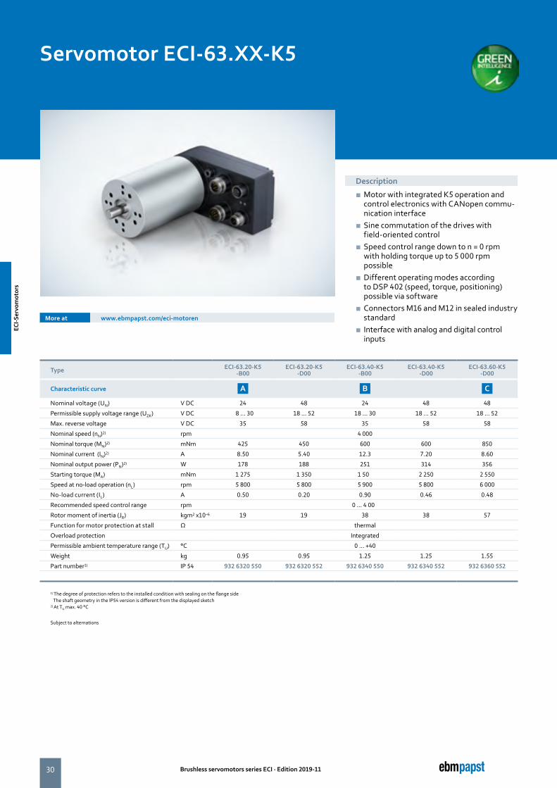
Servomotor ECI-63.XX-K5
Type ECI-63.20-K5 -B00
ECI-63.20-K5 -D00
ECI-63.40-K5-B00
ECI-63.40-K5-D00
ECI-63.60-K5-D00
Characteristic curve A B C
Nominal voltage (UN) V DC 24 48 24 48 48
Permissible supply voltage range (UZK) V DC 18 ... 30 18 ... 52 18 ... 30 18 ... 52 18 ... 52
Max. reverse voltage V DC 35 58 35 58 58
Nominal speed (nN)2) rpm 4 000
Nominal torque (MN)2) mNm 425 450 600 600 850
Nominal current (IN)2) A 8.50 5.40 12.3 7.20 8.60
Nominal output power (PN)2) W 178 188 251 314 356
Starting torque (MA) mNm 1 275 1 350 1 500 2 250 2 550
Speed at no-load operation (nL) rpm 5 800 5 800 5 900 5 800 6 000
No-load current (IL) A 0.50 0.20 0.90 0.46 0.48
Recommended speed control range rpm 0 ... 4 000
Rotor moment of inertia (JR) kgm2 x10–6 19 19 38 38 57
Function for motor protection at stall Ω thermal
Overload protection Integrated
Permissible ambient temperature range (TU) °C 0 ... +40
Weight kg 0.95 0.95 1.25 1.25 1.55
Part number1) IP 54 932 6320 550 932 6320 552 932 6340 550 932 6340 552 932 6360 552
1) The degree of protection refers to the installed condition with sealing on the flange side The shaft geometry in the IP54 version is different from the displayed sketch2) At TU max. 40 °C
Subject to alternations
More at www.ebmpapst.com/eci-motoren
Description
■ Motor with integrated K5 operation and control electronics with CANopen commu-nication interface
■ Sine commutation of the drives with field-oriented control
■ Speed control range down to n = 0 rpm with holding torque up to 5 000 rpm possible
■ Different operating modes according to DSP 402 (speed, torque, positioning) possible via software
■ Connectors M16 and M12 in sealed industry standard
■ Interface with analog and digital control inputs
ECI-S
ervo
mot
ors
ECI-S
ervo
mot
ors
31Brushless servomotors series ECI · Edition 2019-11
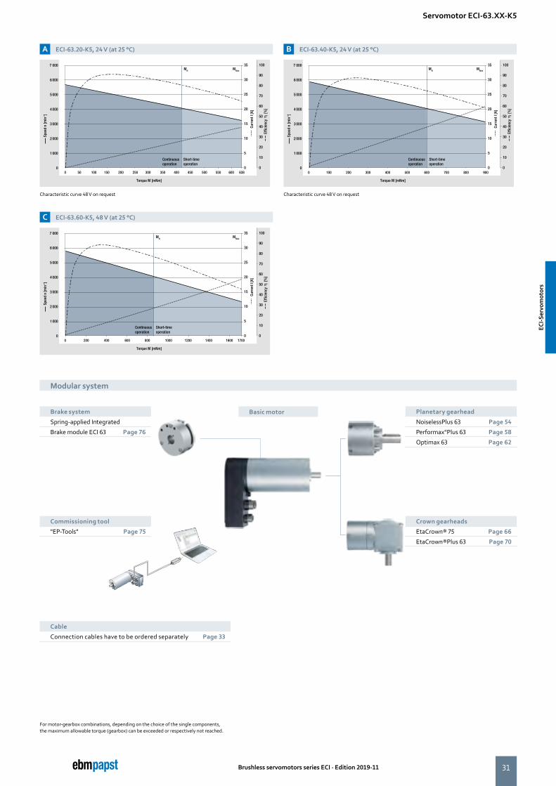
A ECI-63.20-K5, 24 V (at 25 °C)
C ECI-63.60-K5, 48 V (at 25 °C)
B ECI-63.40-K5, 24 V (at 25 °C)
Characteristic curve 48 V on request Characteristic curve 48 V on request
For motor-gearbox combinations, depending on the choice of the single components, the maximum allowable torque (gearbox) can be exceeded or respectively not reached.
Modular system
Basic motor Planetary gearhead
NoiselessPlus 63 Page 54
Performax®Plus 63 Page 58
Optimax 63 Page 62
Modular system
Servomotor ECI-63.XX-K5
Crown gearheads
EtaCrown® 75 Page 66
EtaCrown®Plus 63 Page 70
7 000
6 000
5 000
4 000
3 000
2 000
1 000
0
MN MMax
35
30
25
20
15
10
5
00 50 100 150 200 250 300 350 500 550 600 638400 450
100
90
80
70
60
50
40
30
20
10
0
Torque M [mNm]
Spee
d n
[min
-1]
Curr
ent I
[A]
Short-time operation
Effic
ienc
y
[%
]
Continuousoperation
7 000
6 000
5 000
4 000
3 000
2 000
1 000
0
MN MMax
35
30
25
20
15
10
5
00 200 400 600 800 1000 1200 1400 1600 1700
100
90
80
70
60
50
40
30
20
10
0
Torque M [mNm]
Spee
d n
[min
-1]
Curr
ent I
[A]
Short-time operation
Effic
ienc
y
[%
]
Continuousoperation
7 000
6 000
5 000
4 000
3 000
2 000
1 000
0
MN MMax
35
30
25
20
15
10
5
00 100 200 300 400 500 600 700 800 900
100
90
80
70
60
50
40
30
20
10
0
Torque M [mNm]
Spee
d n
[min
-1]
Curr
ent I
[A]
Short-time operation
Effic
ienc
y
[%
]
Continuousoperation
Commissioning tool
"EP-Tools" Page 75
Brake system
Spring-applied Integrated
Brake module ECI 63 Page 76
Cable
Connection cables have to be ordered separately Page 33
ECI-S
ervo
mot
ors
ECI-S
ervo
mot
ors
32
12
7
11
8
10
9
3
BAC
4
2
5
1
6
43
5
12
34
5
21
3
1
CB
24
PEA
23 4
15
Ø 49
Power
CAN-Out
Signal
CAN-IN
LED
Ø 40
Ø 36
127,
1
4 x 90°
30°
4 x 90
°L 20±0,3
2±0,1
33,5
50,3
D
Ø 25
-0,0
4
Ø 63
±0,
2
64,5
1 2
33
33
23 4
15
Ø 49
Power
CAN-Out
Signal
CAN-IN
LED
Ø 40
Ø 36
127,
1
4 x 90°
30°
4 x 90
°L 20±0,3
2±0,1
33,5
50,3
D
Ø 25
-0,0
4
Ø 63
±0,
2
64,5
1 2
33
33
Brushless servomotors series ECI · Edition 2019-11
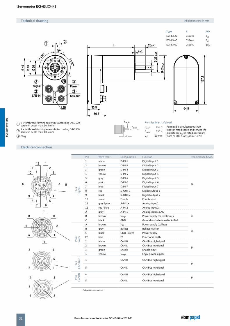
Pin Wire color Configuration Function recommended AWG
SPlu
g Si
gnal
1 white D-IN-1 Digital input 1
24
2 brown D-IN-2 Digital input 2
3 green D-IN-3 Digital input 3
4 yellow D-IN-4 Digital input 4
5 gray D-IN-5 Digital input 5
6 pink D-IN-6 Digital input 6
7 blue D-IN-7 Digital input 7
8 red D-OUT-1 Digital output 1
9 black D-OUT-2 Digital output 2
10 violet Enable Enable input
11 gray / pink A-IN-1+ Analog input 1
12 red / blue A-IN-2 Analog input 2
A gray A-IN-1- Analog input 1 GND
18B brown ULogic Power supply for electronics
C black GND Ground and reference for A-IN-2
Plug
Pow
err
A brown UZK Power supply (ballast)
16B gray Ballast Ballast resistor
C black GND-Power Power supply
FE blue FE Functional earth
1 white CAN H CAN Bus high signal
242 brown CAN L CAN Bus low signal
3 green Enable Enable input
4 yellow ULogik Logic power supply
Plug
CA
N O
ut 4 CAN H CAN Bus high signal24
5 CAN L CAN Bus low signal
Plug
CA
N IN 4 CAN H CAN Bus high signal
245 CAN L CAN Bus low signal
Subject to alternations
Faxial 150 N
Fradial 150 N
L1 20 mm
Faxial
Fradial
L1
Permissible simultaneous shaft Nenn und einer Lebensdauer erwartung L10 (im Nennbetrieb) von 20 000 h (TU max. 40 °C)
Servomotor ECI-63.XX-K5
① 8 x for thread-forming screws M4 according DIN7500. screw-in depth max. 10.5 mm
② 4 x for thread-forming screws M5 according DIN7500. screw-in depth max. 10.5 mm
③ Plug
Faxial
Fradial
L1
Permissible shaft load
Faxial: 150 N Permissible simultaneous shaft loads at rated speed and service life expectancy L10 (in rated operation) from 20 000 h (at TU max. 40 °C)
Fradial: 150 N
L1: 20 mm
Technical drawing All dimensions in mm
Electrical connection
Type L ØD
ECI-63.20 112±0.7 6g5
ECI-63.40 132±0.7 6g5
ECI-63.60 152±0.7 10g5
ECI-S
ervo
mot
ors
ECI-S
ervo
mot
ors
33
LL
L
LL
L
Brushless servomotors series ECI · Edition 2019-11
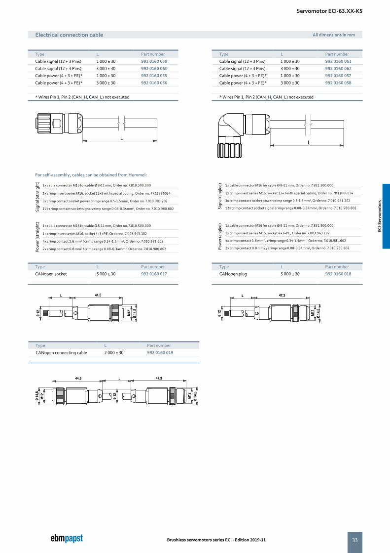
Type L Part number
CANopen connecting cable 2 000 ± 30 992 0160 019
Sign
al (s
trai
ght) 1x cable connector M16 for cable Ø 8-11 mm, Order no. 7.810.500.000
1x crimp insert series M16. socket 12+3 with special coding, Order no. 7K11886034
3x crimp contact socket power crimp range 0.5-1.5mm2, Order no. 7.010.981.202
12x crimp contact socket signal crimp range 0.08-0.34mm2, Order no. 7.010.980.802 Sign
al (a
ngle
d) 1x cable connector M16 for cable Ø 8-11 mm, Order no. 7.831.500.000
1x crimp insert series M16, socket 12+3 with special coding, Order no. 7K11886034
3x crimp contact socket power crimp range 0.5-1.5mm2, Order no. 7.010.981.202
12x crimp contact socket signal crimp range 0.08-0.34mm2, Order no. 7.010.980.802
Pow
er (s
trai
ght) 1x cable connector M16 for cable Ø 8-11 mm, Order no. 7.810.500.000
1x crimp insert series M16. socket 4+3+PE, Order no. 7.003.943.102
4x crimp contact 1.6 mm2 / crimp range 0.34-1.5mm2, Order no. 7.010.981.602
2x crimp contact 0.8 mm2 / crimp range 0.08-0.34mm2, Order no. 7.010.980.802 Pow
er (a
ngle
d) 1x cable connector M16 for cable Ø 8-11 mm, Order no. 7.831.500.000
1x crimp insert series M16, socket 4+3+PE, Order no. 7.003.943.102
4x crimp contact 1.6 mm2 / crimp range 0.34-1.5mm2, Order no. 7.010.981.602
2x crimp contact 0.8 mm2 / crimp range 0.08-0.34mm2, Order no. 7.010.980.802
Type L Part number
CANopen plug 5 000 ± 30 992 0160 018
Type L Part number
CANopen socket 5 000 ± 30 992 0160 017
For self-assembly, cables can be obtained from Hummel:
Type L Part number
Cable signal (12 + 3 Pins) 1 000 ± 30 992 0160 059
Cable signal (12 + 3 Pins) 3 000 ± 30 992 0160 060
Cable power (4 + 3 + FE)* 1 000 ± 30 992 0160 055
Cable power (4 + 3 + FE)* 3 000 ± 30 992 0160 056
* Wires Pin 1, Pin 2 (CAN_H, CAN_L) not executed
Electrical connection cable All dimensions in mm
Type L Part number
Cable signal (12 + 3 Pins) 1 000 ± 30 992 0160 061
Cable signal (12 + 3 Pins) 3 000 ± 30 992 0160 062
Cable power (4 + 3 + FE)* 1 000 ± 30 992 0160 057
Cable power (4 + 3 + FE)* 3 000 ± 30 992 0160 058
* Wires Pin 1, Pin 2 (CAN_H, CAN_L) not executed
Servomotor ECI-63.XX-K5
ECI-S
ervo
mot
ors
ECI-S
ervo
mot
ors
34 Brushless servomotors series ECI · Edition 2019-11
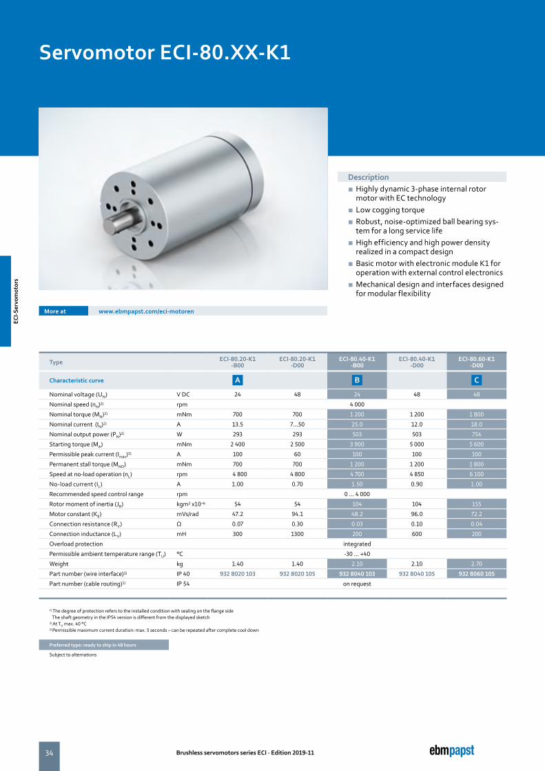
Servomotor ECI-80.XX-K1
Type ECI-80.20-K1 -B00
ECI-80.20-K1 -D00
ECI-80.40-K1 -B00
ECI-80.40-K1 -D00
ECI-80.60-K1 -D00
Characteristic curve A B C
Nominal voltage (UN) V DC 24 48 24 48 48
Nominal speed (nN)2) rpm 4 000
Nominal torque (MN)2) mNm 700 700 1 200 1 200 1 800
Nominal current (IN)2) A 13.5 7...50 25.0 12.0 18.0
Nominal output power (PN)2) W 293 293 503 503 754
Starting torque (MA) mNm 2 400 2 500 3 900 5 000 5 600
Permissible peak current (Imax)3) A 100 60 100 100 100
Permanent stall torque (MNO) mNm 700 700 1 200 1 200 1 800
Speed at no-load operation (nL) rpm 5 4 800 4 800 4 700 4 850 6 100
No-load current (IL) A 1.00 0.70 1.50 0.90 1.00
Recommended speed control range rpm 0 ... 4 000
Rotor moment of inertia (JR) kgm2 x10–6 54 54 104 104 155
Motor constant (KE) mVs/rad 47.2 94.1 48.2 96.0 72.2
Connection resistance (RV) Ω 0.07 0.30 0.03 0.10 0.04
Connection inductance (LV) mH 300 1300 200 600 200
Overload protection integrated
Permissible ambient temperature range (TU) °C -30 ... +40
Weight kg 1.40 1.40 2.10 2.10 2.70
Part number (wire interface)1) IP 40 932 8020 103 932 8020 105 932 8040 103 932 8040 105 932 8060 105
Part number (cable routing)1) IP 54 on request
1) The degree of protection refers to the installed condition with sealing on the flange side The shaft geometry in the IP54 version is different from the displayed sketch2) At TU max. 40 °C3) Permissible maximum current duration: max. 5 seconds – can be repeated after complete cool down
Preferred type: ready to ship in 48 hours
Subject to alternations
More at www.ebmpapst.com/eci-motoren
Description ■ Highly dynamic 3-phase internal rotor motor with EC technology
■ Low cogging torque ■ Robust, noise-optimized ball bearing sys-tem for a long service life
■ High efficiency and high power density realized in a compact design
■ Basic motor with electronic module K1 for operation with external control electronics
■ Mechanical design and interfaces designed for modular flexibility
ECI-S
ervo
mot
ors
ECI-S
ervo
mot
ors
35Brushless servomotors series ECI · Edition 2019-11
Recommended external control electronics
VTD-XX.XX-K4S Speed Page 42
VTD-60.13-K5SB Position Page 44
VTD-60.35-K5SB Position Page 46
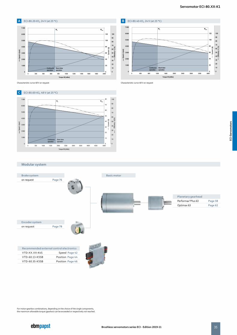
A ECI-80.20-K1, 24 V (at 25 °C)
C ECI-80.60-K1, 48 V (at 25 °C)
B ECI-80.40-K1, 24 V (at 25 °C)
Characteristic curve 48 V on request Characteristic curve 48 V on request
For motor-gearbox combinations, depending on the choice of the single components, the maximum allowable torque (gearbox) can be exceeded or respectively not reached.
Modular system
Basic motorBrake system
on request Page 76
Encoder system
on request Page 78
Modular system
Servomotor ECI-80.XX-K1
Planetary gearhead
Performax®Plus 63 Page 58
Optimax 63 Page 62
7 000
6 000
5 000
4 000
3 000
2 000
1 000
0
MN MMax
120
100
80
60
40
20
00 200 400 2000600 800 1000 1200 1400 1600 1800
100
90
80
70
60
50
40
30
20
10
0
Torque M [mNm]
Spee
d n
[rpm
]
Curr
ent I
[A]
Short-time operation
Effic
ienc
y
[%
]
Continuousoperation
Torque M [mNm]
Spee
d n
[rpm
]
7 000
6 000
5 000
4 000
3 000
2 000
1 000
0
Curr
ent I
[A]
MN MMax
Effic
ienc
y
[%
]
80
60
40
20
00 500 1000 50001500 2000 2500 3000 3500 4000 4500
100
90
80
70
60
50
40
30
20
10
0
70
50
30
10Short-time operation
Continuousoperation
7 000
6 000
5 000
4 000
3 000
2 000
1 000
0
MN MMax
120
100
80
60
40
20
00 400 800 1200 1600 2000 2400 2800 3200 3600
100
90
80
70
60
50
40
30
20
10
0
Torque M [mNm]
Spee
d n
[rpm
]
Curr
ent I
[A]
Short-time operation
Effic
ienc
y
[%
]
Continuousoperation
ECI-S
ervo
mot
ors
ECI-S
ervo
mot
ors
36
3 2 1
4 x 90°
4 x
90°
45° 45°2 x 6
0°
°09 x 4
Ø 80
±0,
2
Ø 45
Ø 56
Ø 60
L1
L2 30±0,3
3±0,1
Ø 15
+0,
009
+0,
015
Ø 32
-0,0
5
12
4 x 90°
4 x
90°
45° 45°2 x 6
0°
°09 x 4
Ø 80
±0,
2
Ø 45
Ø 56
Ø 60
L1
L2 30±0,3
3±0,1
Ø 15
+0,
009
+0,
015
Ø 32
-0,0
5
12
Brushless servomotors series ECI · Edition 2019-11
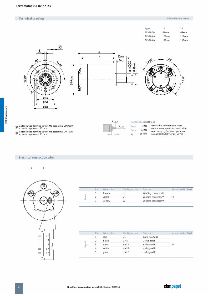
Servomotor ECI-80.XX-K1
Technical drawing All dimensions in mm
Electrical connection wire
Type L1 L2
ECI-80.20 89±0.3 69±0.3
ECI-80.40 109±0.3 116±0.3
ECI-80.60 129±0.3 136±0.3
① 8 x for thread-forming screws M6 according DIN7500, screw-in depth max. 13 mm
② 4 x for thread-forming screws M5 according DIN7500, screw-in depth max. 13 mm
Faxial
Fradial
L1
Permissible shaft load
Faxial: 70 N Permissible simultaneous shaft loads at rated speed and service life expectancy L10 (in rated operation) from 20 000 h (at TU max. 40 °C)
Fradial: 330 N
L1: 15 mm
Pin Wire color Configuration Function recommended AWG
Sign
al
1 red UB supply voltage
24
2 black GND Ground Hall
3 green Hall A Hall signal A
4 white Hall B Hall signal B
5 gray Hall C Hall signal C
Pin Wire color Configuration Function recommended AWG
Pow
er
1 brown U Winding connector U
122 violet V Winding connector V
3 yellow W Winding connector W
ECI-S
ervo
mot
ors
ECI-S
ervo
mot
ors
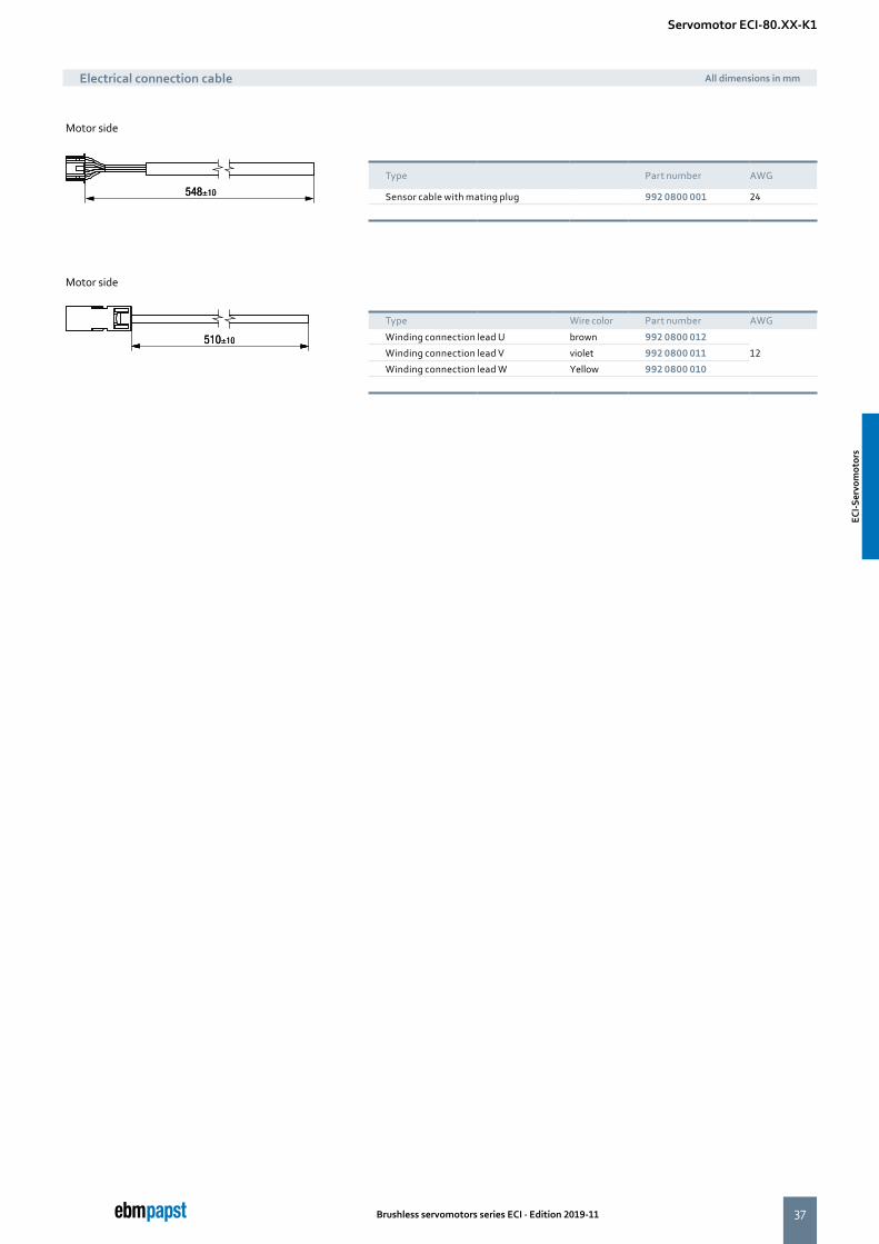
37Brushless servomotors series ECI · Edition 2019-11
Type Wire color Part number AWG
Winding connection lead U brown 992 0800 012
12 Winding connection lead V violet 992 0800 011
Winding connection lead W Yellow 992 0800 010
Motor side
Motor side
Servomotor ECI-80.XX-K1
Electrical connection cable All dimensions in mm
Type Part number AWG
Sensor cable with mating plug 992 0800 001 24
ECI-S
ervo
mot
ors
ECI-S
ervo
mot
ors
38 Brushless servomotors series ECI · Edition 2019-11
the engineer’s choice
39Brushless servomotors series ECI · Edition 2019-11
Page
VTD-XX.XX-K3 (speed) 40
VTD-XX.XX-K4S (position) 42
VTD-60.13-K5SB (CANopen) 44
VTD-60.35-K5SB (CANopen) 46
Control electronics
Cntr
ol e
lect
roni
cs
Cont
rol e
lect
roni
cs
40 Brushless servomotors series ECI · Edition 2019-11
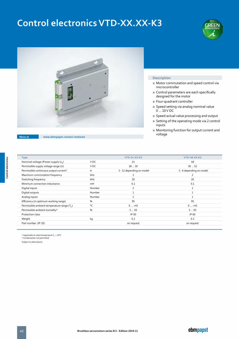
Control electronics VTD-XX.XX-K3
Description ■ Motor commutation and speed control via microcontroller
■ Control parameters are each specifically designed for the motor
■ Four-quadrant controller ■ Speed setting via analog nominal value 0 ... 10 V DC
■ Speed actual value processing and output ■ Setting of the operating mode via 2 control inputs
■ Monitoring function for output current and voltage
More at www.ebmpapst.com/eci-motoren
Type VTD-24.XX-K3 VTD-48.XX-K3
Nominal voltage (Power supply UN) V DC 24 48
Permissible supply voltage range (U) V DC 18 ... 30 30 ... 52
Permissible continuous output current1) A 3 - 12 depending on model 3 - 6 depending on model
Maximum commutation frequency kHz 2 2
Switching frequency kHz 20 20
Minimum connection inductance mH 0.1 0.1
Digital inputs Number 2 2
Digital outputs Number 1 1
Analog inputs Number 1 1
Efficiency (in optimum working range) % 95 95
Permissible ambient temperature range (TU) °C 0 ... +40 0 ... +40
Permissible ambient humidity2) % 5 ... 93 5 ... 93
Protection class IP 00 IP 00
Weight kg 0.2 0.2
Part number (IP 20) on request on request
1) Applicable at rated temperature TU = 40°C 2) Condensation not permitted
Subject to alternations
Cont
rol e
lect
roni
cs
Cont
rol e
lect
roni
cs
41Brushless servomotors series ECI · Edition 2019-11
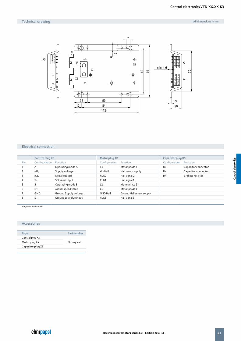
Control electronics VTD-XX.XX-K3
Technical drawing All dimensions in mm
Electrical connection
Accessories
Type Part number
Control plug X3
On requestMotor plug X4
Capacitor plug X5
Control plug X3 Motor plug X4 Capacitor plug X5
Pin Configuration Function Configuration Function Configuration Function
1 A Operating mode A L3 Motor phase 3 U+ Capacitor connector
2 +UB Supply voltage +U-Hall Hall sensor supply U- Capacitor connector
3 n.c. Not allocated RLG2 Hall signal 2 BR Braking resistor
4 S+ Set value input RLG1 Hall signal 1
5 B Operating mode B L2 Motor phase 2
6 Ist Actual speed value L1 Motor phase 1
7 GND Ground Supply voltage GND Hall Ground Hall sensor supply
8 S- Ground set value input RLG3 Hall signal 3
Subject to alternations
Cont
rol e
lect
roni
cs
Cont
rol e
lect
roni
cs
42 Brushless servomotors series ECI · Edition 2019-11
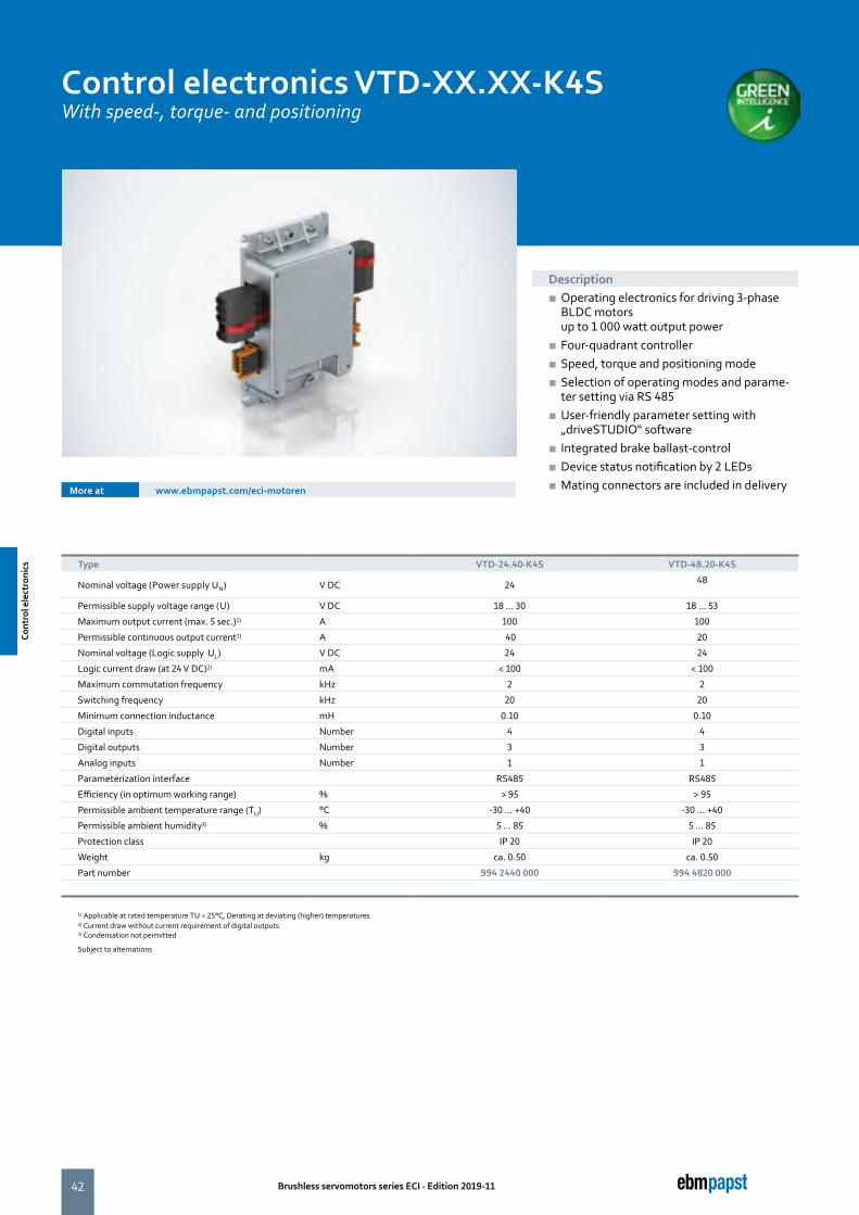
Control electronics VTD-XX.XX-K4SWith speed-, torque- and positioning
More at www.ebmpapst.com/eci-motoren
Description ■ Operating electronics for driving 3-phase BLDC motors up to 1 000 watt output power
■ Four-quadrant controller ■ Speed, torque and positioning mode ■ Selection of operating modes and parame-ter setting via RS 485
■ User-friendly parameter setting with „driveSTUDIO“ software
■ Integrated brake ballast-control ■ Device status notification by 2 LEDs ■ Mating connectors are included in delivery
Type VTD-24.40-K4S VTD-48.20-K4S
Nominal voltage (Power supply UN) V DC 24 48
Permissible supply voltage range (U) V DC 18 ... 30 18 ... 53
Maximum output current (max. 5 sec.)1) A 100 100
Permissible continuous output current1) A 40 20
Nominal voltage (Logic supply UL) V DC 24 24
Logic current draw (at 24 V DC)2) mA < 100 < 100
Maximum commutation frequency kHz 2 2
Switching frequency kHz 20 20
Minimum connection inductance mH 0.10 0.10
Digital inputs Number 4 4
Digital outputs Number 3 3
Analog inputs Number 1 1
Parameterization interface RS485 RS485
Efficiency (in optimum working range) % > 95 > 95
Permissible ambient temperature range (TU) °C -30 ... +40 -30 ... +40
Permissible ambient humidity3) % 5 ... 85 5 ... 85
Protection class IP 20 IP 20
Weight kg ca. 0.50 ca. 0.50
Part number 994 2440 000 994 4820 000
1) Applicable at rated temperature TU = 25°C, Derating at deviating (higher) temperatures 2) Current draw without current requirement of digital outputs3) Condensation not permitted
Subject to alternations
Cont
rol e
lect
roni
cs
Cont
rol e
lect
roni
cs
43
96 41
157
X 106
X 100
X 102
X 107
X 101
Status LEDs
FE
UZK
P-GND
BALLAST
4
3
2
1
1
2
3
4
NCGNDSINCDSFE
X101
X107 U
V
W
FE
X106
+5VGNDHALL AHALL BHALL C
FEGNDU-LOGIKO-DUT 3O-DUT 2O-DUT 1
A-GNDA-IN-1IN-2O-IN-1O-IN-BO-IN-A
RS485 A (+)RS485 B (-)FE
RS485 A (+)RS485 B (-)FE
X100
X102 678910
12345
654321
121110987
321
654
Brushless servomotors series ECI · Edition 2019-11
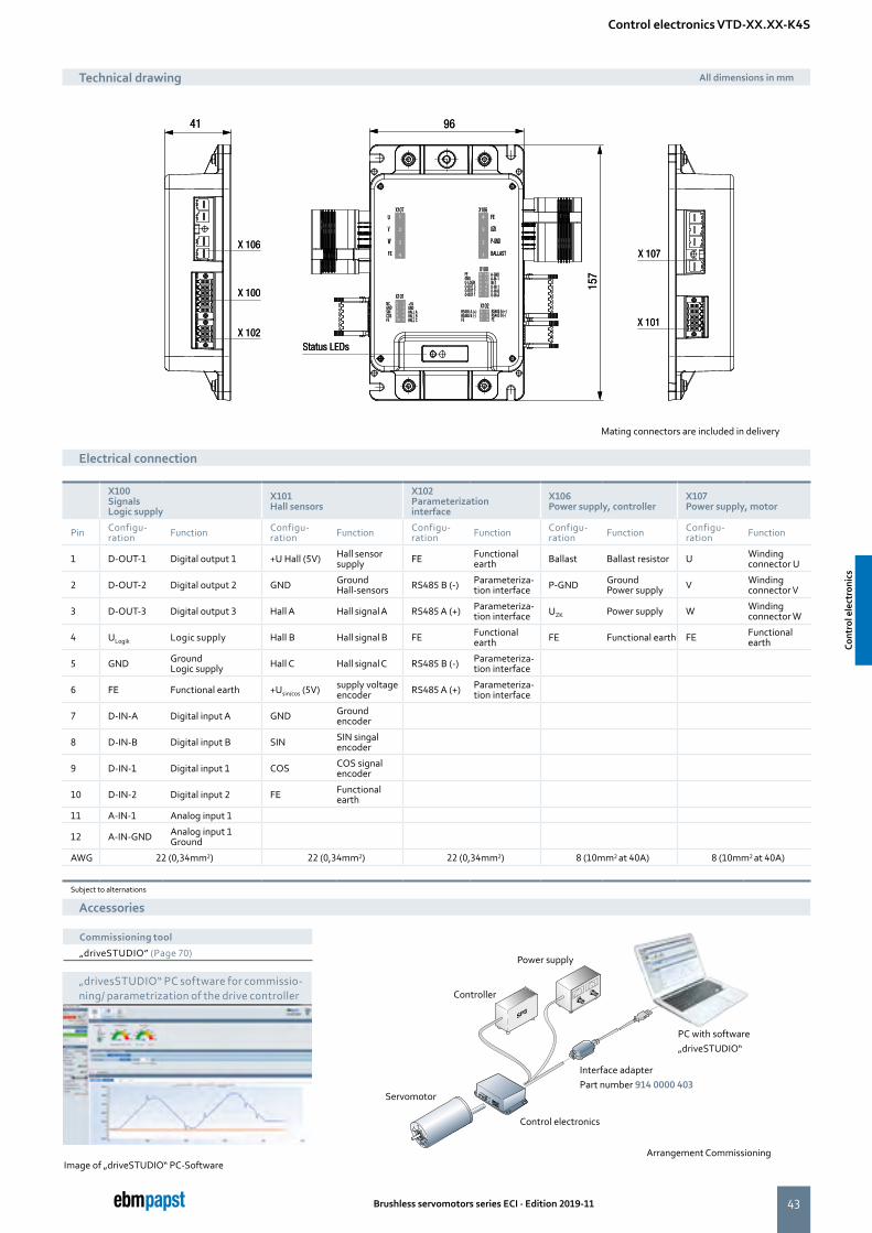
Control electronics VTD-XX.XX-K4S
Technical drawing All dimensions in mm
Electrical connection
Accessories
X100 Signals Logic supply
X101 Hall sensors
X102 Parameterization interface
X106 Power supply, controller
X107 Power supply, motor
Pin Configu- ration Function Configu-
ration Function Configu- ration Function Configu-
ration Function Configu- ration Function
1 D-OUT-1 Digital output 1 +U Hall (5V) Hall sensor supply FE Functional
earth Ballast Ballast resistor U Winding connector U
2 D-OUT-2 Digital output 2 GND Ground Hall-sensors RS485 B (-) Parameteriza-
tion interface P-GND Ground Power supply V Winding
connector V
3 D-OUT-3 Digital output 3 Hall A Hall signal A RS485 A (+) Parameteriza-tion interface UZK Power supply W Winding
connector W
4 ULogik Logic supply Hall B Hall signal B FE Functional earth FE Functional earth FE Functional
earth
5 GND Ground Logic supply Hall C Hall signal C RS485 B (-) Parameteriza-
tion interface
6 FE Functional earth +Usin/cos (5V) supply voltage encoder RS485 A (+) Parameteriza-
tion interface
7 D-IN-A Digital input A GND Ground encoder
8 D-IN-B Digital input B SIN SIN singal encoder
9 D-IN-1 Digital input 1 COS COS signal encoder
10 D-IN-2 Digital input 2 FE Functional earth
11 A-IN-1 Analog input 1
12 A-IN-GND Analog input 1 Ground
AWG 22 (0,34mm2) 22 (0,34mm2) 22 (0,34mm2) 8 (10mm2 at 40A) 8 (10mm2 at 40A)
Subject to alternations
PC with software„driveSTUDIO“
Power supply
Controller
Servomotor
Control electronics
Interface adapterPart number 914 0000 403
Image of „driveSTUDIO“ PC-Software
Commissioning tool
„driveSTUDIO” (Page 70)
„drivesSTUDIO“ PC software for commissio-ning/ parametrization of the drive controller
Mating connectors are included in delivery
Arrangement Commissioning
Cont
rol e
lect
roni
cs
Cont
rol e
lect
roni
cs
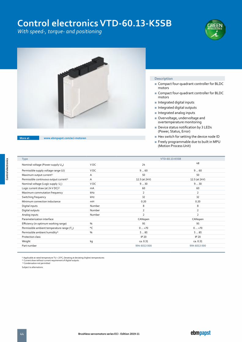
44 Brushless servomotors series ECI · Edition 2019-11
Control electronics VTD-60.13-K5SBWith speed-, torque- and positioning
More at www.ebmpapst.com/eci-motoren
Description ■ Compact four-quadrant controller for BLDC motors
■ Compact four-quadrant controller for BLDC motors
■ Integrated digital inputs ■ Integrated digital outputs ■ Integrated analog inputs ■ Overvoltage, undervoltage and overtemperature monitoring
■ Device status notification by 3 LEDs (Power, Status, Error)
■ Hex switch for setting the device node ID ■ Freely programmable due to built in MPU (Motion Process Unit)
Type VTD-60.13-K5SB
Nominal voltage (Power supply UN) V DC 24 48
Permissible supply voltage range (U) V DC 9 ... 60 9 ... 60
Maximum output current1) A 50 50
Permissible continuous output current1) A 12.5 (at 24V) 12.5 (at 24V)
Nominal voltage (Logic supply UL) V DC 9 ... 30 9 ... 30
Logic current draw (at 24 V DC)2) mA 60 60
Maximum commutation frequency kHz 2 2
Switching frequency kHz 32 32
Minimum connection inductance mH 0.20 0.20
Digital inputs Number 8 8
Digital outputs Number 2 2
Analog inputs Number 2 2
Parameterization interface CANopen CANopen
Efficiency (in optimum working range) % 95 95
Permissible ambient temperature range (TU) °C 0 ... +70 0 ... +70
Permissible ambient humidity3) % 5 ... 85 5 ... 85
Protection class IP 20 IP 20
Weight kg ca. 0.31 ca. 0.31
Part number 994 6013 000 994 6013 000
1) Applicable at rated temperature TU = 25°C, Derating at deviating (higher) temperatures2) Current draw without current requirement of digital outputs 3) Condensation not permitted
Subject to alternations
Cont
rol e
lect
roni
cs
Cont
rol e
lect
roni
cs
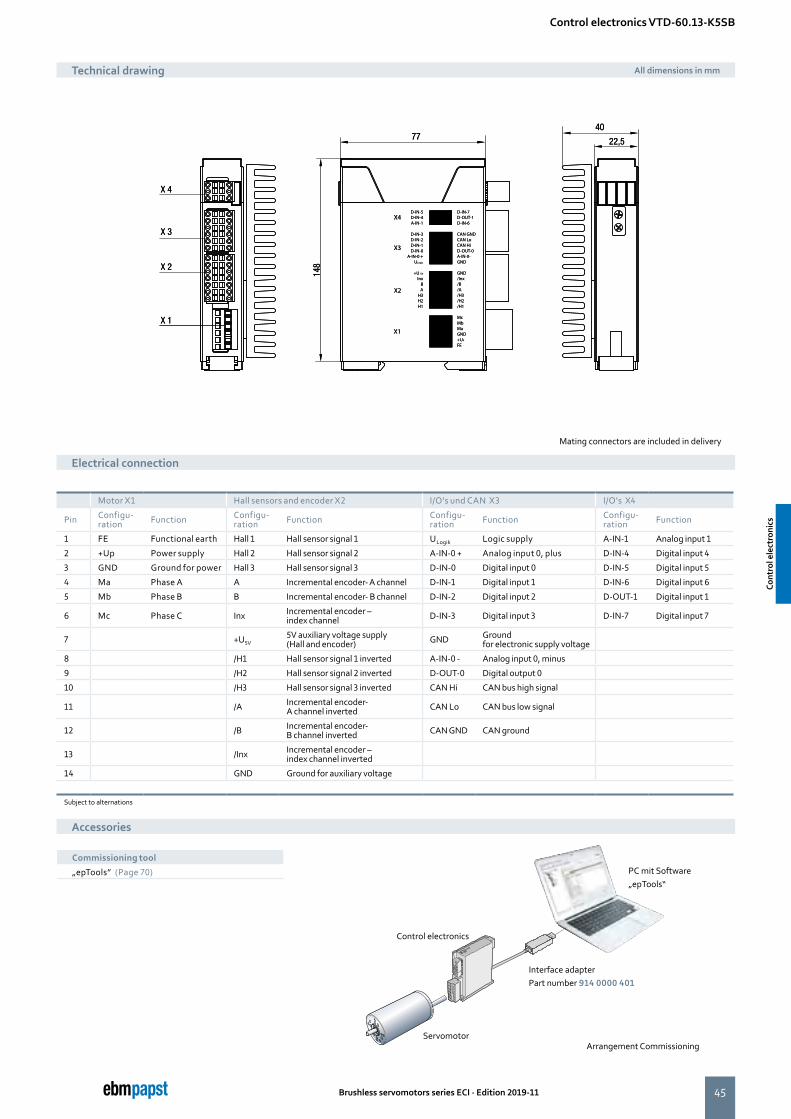
45
D-IN-7D-OUT-1D-IN-6
CAN GNDCAN LoCAN HiD-OUT-0A-IN-0-GND
GND/Inx/B/A/H3/H2/H1
McMbMaGND+UP
FE
3 2 1
6 5 4 3 2 1
7 6 5 4 3 2 1
654
12 1110
987
1413121110
98
6 5 4 3 2 1
D-IN-5D-IN-4A-IN-1
D-IN-3D-IN-2D-IN-1D-IN-0
A-IN-0 +ULogic
+U 5V
InxBA
H3H2H1
X1
X2
X3
X4D-IN-7D-OUT-1D-IN-6
CAN GNDCAN LoCAN HiD-OUT-0A-IN-0-GND
GND/Inx/B/A/H3/H2/H1
McMbMaGND+UP
FE
3 2 1
6 5 4 3 2 1
7 6 5 4 3 2 1
654
12 1110
987
1413121110
98
6 5 4 3 2 1
D-IN-5D-IN-4A-IN-1
D-IN-3D-IN-2D-IN-1D-IN-0
A-IN-0 +ULogic
+U 5V
InxBA
H3H2H1
X1
X2
X3
X4
Brushless servomotors series ECI · Edition 2019-11
Control electronics VTD-60.13-K5SB
Technical drawing All dimensions in mm
Accessories
Mating connectors are included in delivery
Motor X1 Hall sensors and encoder X2 I/O's und CAN X3 I/O's X4
Pin Configu- ration Function Configu-
ration Function Configu- ration Function Configu-
ration Function
1 FE Functional earth Hall 1 Hall sensor signal 1 ULogik Logic supply A-IN-1 Analog input 1
2 +Up Power supply Hall 2 Hall sensor signal 2 A-IN-0 + Analog input 0, plus D-IN-4 Digital input 4
3 GND Ground for power Hall 3 Hall sensor signal 3 D-IN-0 Digital input 0 D-IN-5 Digital input 5
4 Ma Phase A A Incremental encoder- A channel D-IN-1 Digital input 1 D-IN-6 Digital input 6
5 Mb Phase B B Incremental encoder- B channel D-IN-2 Digital input 2 D-OUT-1 Digital input 1
6 Mc Phase C Inx Incremental encoder – index channel D-IN-3 Digital input 3 D-IN-7 Digital input 7
7 +U5V5V auxiliary voltage supply (Hall and encoder) GND Ground
for electronic supply voltage
8 /H1 Hall sensor signal 1 inverted A-IN-0 - Analog input 0, minus
9 /H2 Hall sensor signal 2 inverted D-OUT-0 Digital output 0
10 /H3 Hall sensor signal 3 inverted CAN Hi CAN bus high signal
11 /A Incremental encoder- A channel inverted CAN Lo CAN bus low signal
12 /B Incremental encoder- B channel inverted CAN GND CAN ground
13 /Inx Incremental encoder – index channel inverted
14 GND Ground for auxiliary voltage
Subject to alternations
Electrical connection
PC mit Software„epTools“
ServomotorArrangement Commissioning
Interface adapter Part number 914 0000 401
Control electronics
Commissioning tool
„epTools” (Page 70)
Cont
rol e
lect
roni
cs
Cont
rol e
lect
roni
cs

46 Brushless servomotors series ECI · Edition 2019-11
Control electronics VTD-60.35-K5SBWith speed-, torque- and positioning
More at www.ebmpapst.com/eci-motoren
Description ■ Compact four-quadrant controller for BLDC motors
■ CANopen interface (Protocol DS301, Device profile DS402)
■ Integrated digital inputs ■ Integrated digital outputs ■ Integrated analog inputs ■ Overvoltage, undervoltage and overtempe-rature monitoring
■ Device status notification by 3 LEDs (Power, Status, Erro
■ Hex switch for setting the device node ID ■ Freely programmable due to built in MPU (Motion Process Unit)
Type VTD-60.35-K5SB
Nominal voltage (Power supply UN) V DC 24 48
Permissible supply voltage range (U) V DC 9 ... 60 9 ... 60
Maximum output current1) A 100 100
Permissible continuous output current1) A 35 (at 24V) 35 (at 24V)
Nominal voltage (Logic supply UL) V DC 9 ... 30 9 ... 30
Logic current draw (at 24 V DC)2) mA 70 70
Maximum commutation frequency kHz 2 2
Switching frequency kHz 32 32
Minimum connection inductance mH 0,20 0,20
Digital inputs Number 8 8
Digital outputs Number 2 2
Analog inputs Number 2 2
Parameterization interface CANopen CANopen
Efficiency (in optimum working range) % 95 95
Permissible ambient temperature range (TU) °C 0 ... +70 0 ... +70
Permissible ambient humidity3) % 5 ... 85 5 ... 85
Protection class IP 20 IP 20
Weight kg ca. 0.38 ca. 0.38
Part number 994 6035 000 994 6035 000
1) Applicable at rated temperature TU = 25°C, Derating at deviating (higher) temperatures2) Current draw without current requirement of digital outputs 3) Condensation not permitted
Subject to alternations
Cont
rol e
lect
roni
cs
Cont
rol e
lect
roni
cs
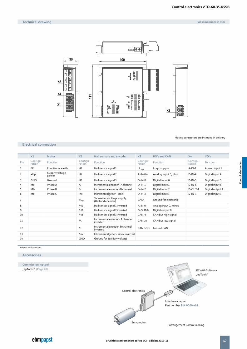
47
30 100
111
X2
1
2
3
4
5
6
X4
X1
X3
GND-AIN-0D-OUT-0HiLoGND
X3CAN + I/O
U Logik+Ain0D-IN-0D-IN-1D-IN-2D-IN-3
789101112
123456
654
121110
654321
7654321
1413121110 9 8
GND/Inx/B/A/H3/H2/H1
+U5VInxBAH3H2H1
X2En
code
r + Ha
ll X4 i/O
X1
Motor
+ Po
wer Mc
MbMaGND+UpFE
Din5Din4Ain1
Din7Dout1Din6
30 100
111
X2
1
2
3
4
5
6
X4
X1
X3
GND-AIN-0D-OUT-0HiLoGND
X3CAN + I/O
U Logik+Ain0D-IN-0D-IN-1D-IN-2D-IN-3
789101112
123456
654
121110
654321
7654321
1413121110 9 8
GND/Inx/B/A/H3/H2/H1
+U5VInxBAH3H2H1
X2En
code
r + Ha
ll X4 i/O
X1
Motor
+ Po
wer Mc
MbMaGND+UpFE
Din5Din4Ain1
Din7Dout1Din6
Brushless servomotors series ECI · Edition 2019-11
X1 Motor X2 Hall sensors and encoder X3 I/O's and CAN X4 I/O's
Pin Configu- ration Function Configu-
ration Function Configu- ration Function Configu-
ration Function
1 FE Functional earth H1 Hall sensor signal 1 ULogik Logic supply A-IN-1 Analog input 1
2 +Up Supply voltage power H2 Hall sensor signal 2 A-IN-0 + Analog input 0, plus D-IN-4 Digital input 4
3 GND Ground H3 Hall sensor signal 3 D-IN-0 Digital input 0 D-IN-5 Digital input 5
4 Ma Phase A A Incremental encoder - A channel D-IN-1 Digital input 1 D-IN-6 Digital input 6
5 Mb Phase B B Incremental encoder- B channel D-IN-2 Digital input 2 D-OUT-1 Digital output 1
6 Mc Phase C Inx Inkrementalgeber - Index D-IN-3 Digital input 3 D-IN-7 Digital input 7
7 +U5V5V auxiliary voltage supply (Hall and encoder) GND Ground for electronic
8 /H1 Hall sensor signal 1 inverted A-IN-0 - Analog input 0, minus
9 /H2 Hall sensor signal 2 inverted D-OUT-0 Digital output 0
10 /H3 Hall sensor signal 3 inverted CAN Hi CAN bus high signal
11 /A Incremental encoder - A channel inverted CAN Lo CAN bus low signal
12 /B Incremental encoder- B channel inverted CAN GND Ground CAN
13 /Inx Inkrementalgeber - Index inverted
14 GND Ground for auxiliary voltage
Subject to alternations
Control electronics VTD-60.35-K5SB
Technical drawing All dimensions in mm
Electrical connection
PC with Software„epTools“
ServomotorArrangement Commissioning
Interface adapterPart number 914 0000 401
Control electronics
Accessories
Commissioning tool
„epTools” (Page 70)
Mating connectors are included in delivery
Cont
rol e
lect
roni
cs
Cont
rol e
lect
roni
cs
48 Brushless servomotors series ECI · Edition 2019-11
the engineer’s choice
49Brushless servomotors series ECI · Edition 2019-11
Page
NoiselessPlus 42 (Planetary gearhead) 52
NoiselessPlus 63 (Planetary gearhead) 54
Performax®Plus 42 (Planetary gearhead) 56
Performax®Plus 63 (Planetary gearhead) 58
Optimax 42 (Planetary gearhead) 60
Optimax 63 (Planetary gearhead) 62
EtaCrown®52 (Crown gearhead) 64
EtaCrown®75 (Crown gearhead) 66
EtaCrown®Plus 42 (Crown gearhead) 68
EtaCrown®Plus 63 (Crown gearhead) 70
Gearheads
Gea
rhea
ds
Gea
rhea
ds
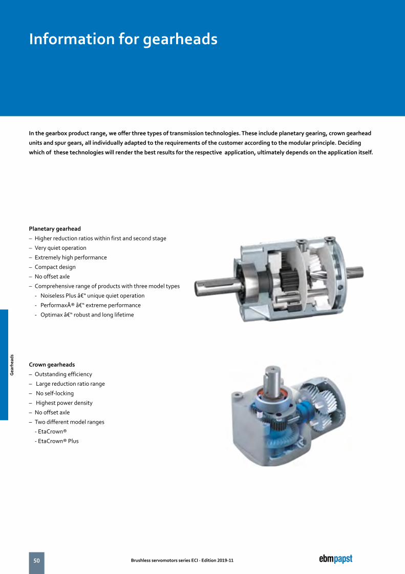
50 Brushless servomotors series ECI · Edition 2019-11
In the gearbox product range, we offer three types of transmission technologies. These include planetary gearing, crown gearhead
units and spur gears, all individually adapted to the requirements of the customer according to the modular principle. Deciding
which of these technologies will render the best results for the respective application, ultimately depends on the application itself.
Planetary gearhead
– Higher reduction ratios within first and second stage
– Very quiet operation
– Extremely high performance
– Compact design
– No offset axle
– Comprehensive range of products with three model types
- Noiseless Plus – unique quiet operation
- Performax® – extreme performance
- Optimax – robust and long lifetime
Crown gearheads
– Outstanding efficiency
– Large reduction ratio range
– No self-locking
– Highest power density
– No offset axle
– Two different model ranges
- EtaCrown®
- EtaCrown® Plus
Information for gearheads
Gea
rhea
ds
Gea
rhea
ds
51Brushless servomotors series ECI · Edition 2019-11
The comprehensive range of planetary gearbox products is used when high power densities are required.
When it comes to achieving high efficiency with minimal noise, the NoiselessPlus is the impressive, obvious choice. Its exemplary smooth operation is achieved thanks to extremely sturdy, helical planetary wheels made of high-strength plastic.
Performax®Plus delivers smooth operation and high performance. Helical planetary wheels made of high-strength plastic ensure excellent smooth operation in the first stage. The combination with a hardened ring gear in the output stage means that high outputs can be achieved. Optimax offers maximum robustness at the highest power density. Straight-toothed planetary wheels made of high-strength steel in the first and second gear stage allow high peak loads and also ensure that the transmission has a long life. If there are increased noise requirements, high-strength plastic planetary wheels can be implemented in the input stage as an option.
ebm-papst impresses with innovative crown gearhead technology in its family of crown gearheads.
The EtaCrown® is a convincing offering with its wide reduction range and compact design. Space can always be saved during installation thanks to zero axle misalignment with a symmetrical structure. High radial loads can also be incorporated via a double ball bearing on the output shaft.
The EtaCrown®Plus requires minimum assembly space while achieving maximum power. Thanks to a downstream planetary stage, it can achieve significantly higher torques compared to the EtaCrown of the same size.
The output shafts of the ebm-papst transmission are generally made of hardened and ground case-hardened steel, meaning that they are particularly durable. Torque is transmitted via a keyway connection as standard.
Gea
rhea
ds
Gea
rhea
ds

52 Brushless servomotors series ECI · Edition 2019-11
Planetary gearhead NoiselessPlus 42
Description
■ Very quiet operation due to helical-tooth gear stages
■ Toothed parts made of plastic with opti-mized sliding properties ensure smooth operation
■ Higher reduction ratios within first and second gear stage
■ High radial loads due to double ball bearing in the output shaft
■ Flexible connection to customer appli-cations (shaft variants, centering and fastening)
More at www.ebmpapst.com/eci-motoren
Image of 1-stage gearhead
Type NoiselessPlus 42.1 NoiselessPlus 42.2
Reduction ratio 4.30 6.00 11.0 21.0 26.0 47.6 66.0 121 231
No. of stages 1 1 1 1 2 2 2 2 2
Efficiency 0.90 0.90 0.90 0.90 0.81 0.81 0.81 0.81 0.81
Max. input speed (n1) rpm 6 000
Rated output torque (Mab) Nm 2.52 1.96 1.10 0.38 4.00 4.28 4.94 3.02 3.66
Short term torque (Mmax) Nm 6.30 4.90 2.75 0.95 10.0 10.7 12.4 7.55 9.15
Gear play ° 0.2 ... 0.5
Permissible operating temperature range °C -20 ... +80
Operating mode S1
Protection class IP 50
Weight kg 0.22 0.22 0.22 0.22 0.25 0.25 0.25 0.25 0.25
Shaft load radial / axial N 50 / 350 80 / 350 175 / 350 220 / 350 250 / 350 520 / 350 680 / 350 900 / 350 1 000 / 350
Service life h 10 000
Lubrication Maintenance free grease lubrication for life
Installation position any
Length mm 40.1 40.1 40.1 40.1 67.1 67.1 67.1 67.1 67.1
Subject to alternations
Gea
rhea
ds
Gea
rhea
ds
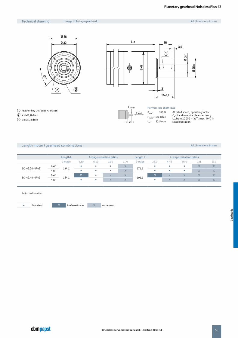
53
16
Ø 8h
7
3,5
Ø 36
Ø 32
45°Ø
25h8
Ø 42
3
L±1
25±0,5
①
② ③
16
Ø 8h
7
3,5
Ø 36
Ø 32
45°Ø
25h8
Ø 42
3
L±1
25±0,5
①
② ③
Brushless servomotors series ECI · Edition 2019-11
Planetary gearhead NoiselessPlus 42
Length motor / gearhead combinations All dimensions in mm
① Feather key DIN 6885 A-3x3x16
② 4 x M3, 8 deep
③ 4 x M4, 8 deep
Faxial
Fradial
L1
Permissible shaft load
Faxial: 350 N At rated speed, operating factor CB=1 and a service life expectancy L10 from 10 000 h (at TU max. 40°C in rated operation)
Fradial: see table
L1: 12.5 mm
Length L 1-stage reduction ratios Length L 2-stage reduction ratios
1-stage 4.30 6.00 11.0 21.0 2-stage 26.0 47.6 66.0 121 231
ECI-42.20-NP4224V
144.1� � � X
171.1� � � X X
48V � � � X � � � X X
ECI-42.40-NP4224V
164.1� � X X
191.1� X X X X
48V � � X X � X X X X
Subject to alternations
Technical drawing Image of 1-stage gearhead All dimensions in mm
� Standard � Preferred type X on request
Gea
rhea
ds
Gea
rhea
ds
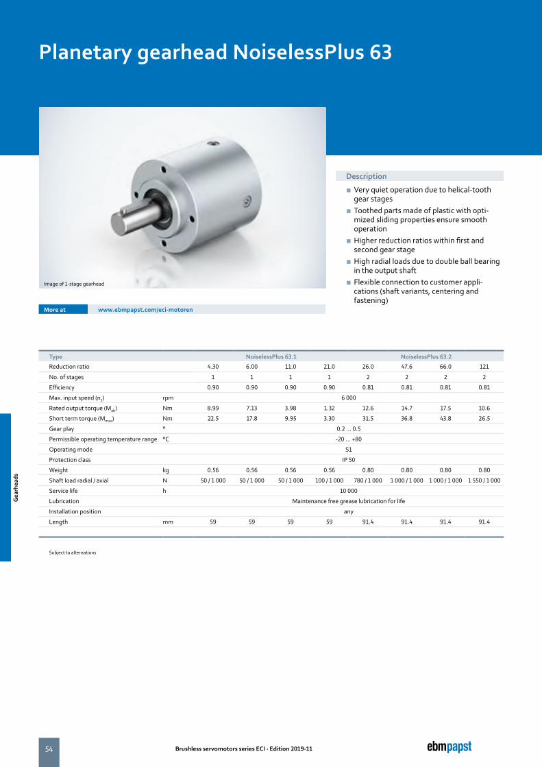
54 Brushless servomotors series ECI · Edition 2019-11
Planetary gearhead NoiselessPlus 63
Description
■ Very quiet operation due to helical-tooth gear stages
■ Toothed parts made of plastic with opti-mized sliding properties ensure smooth operation
■ Higher reduction ratios within first and second gear stage
■ High radial loads due to double ball bearing in the output shaft
■ Flexible connection to customer appli-cations (shaft variants, centering and fastening)
More at www.ebmpapst.com/eci-motoren
Image of 1-stage gearhead
Type NoiselessPlus 63.1 NoiselessPlus 63.2
Reduction ratio 4.30 6.00 11.0 21.0 26.0 47.6 66.0 121
No. of stages 1 1 1 1 2 2 2 2
Efficiency 0.90 0.90 0.90 0.90 0.81 0.81 0.81 0.81
Max. input speed (n1) rpm 6 000
Rated output torque (Mab) Nm 8.99 7.13 3.98 1.32 12.6 14.7 17.5 10.6
Short term torque (Mmax) Nm 22.5 17.8 9.95 3.30 31.5 36.8 43.8 26.5
Gear play ° 0.2 ... 0.5
Permissible operating temperature range °C -20 ... +80
Operating mode S1
Protection class IP 50
Weight kg 0.56 0.56 0.56 0.56 0.80 0.80 0.80 0.80
Shaft load radial / axial N 50 / 1 000 50 / 1 000 50 / 1 000 100 / 1 000 780 / 1 000 1 000 / 1 000 1 000 / 1 000 1 550 / 1 000
Service life h 10 000
Lubrication Maintenance free grease lubrication for life
Installation position any
Length mm 59 59 59 59 91.4 91.4 91.4 91.4
Subject to alternations
Gea
rhea
ds
Gea
rhea
ds
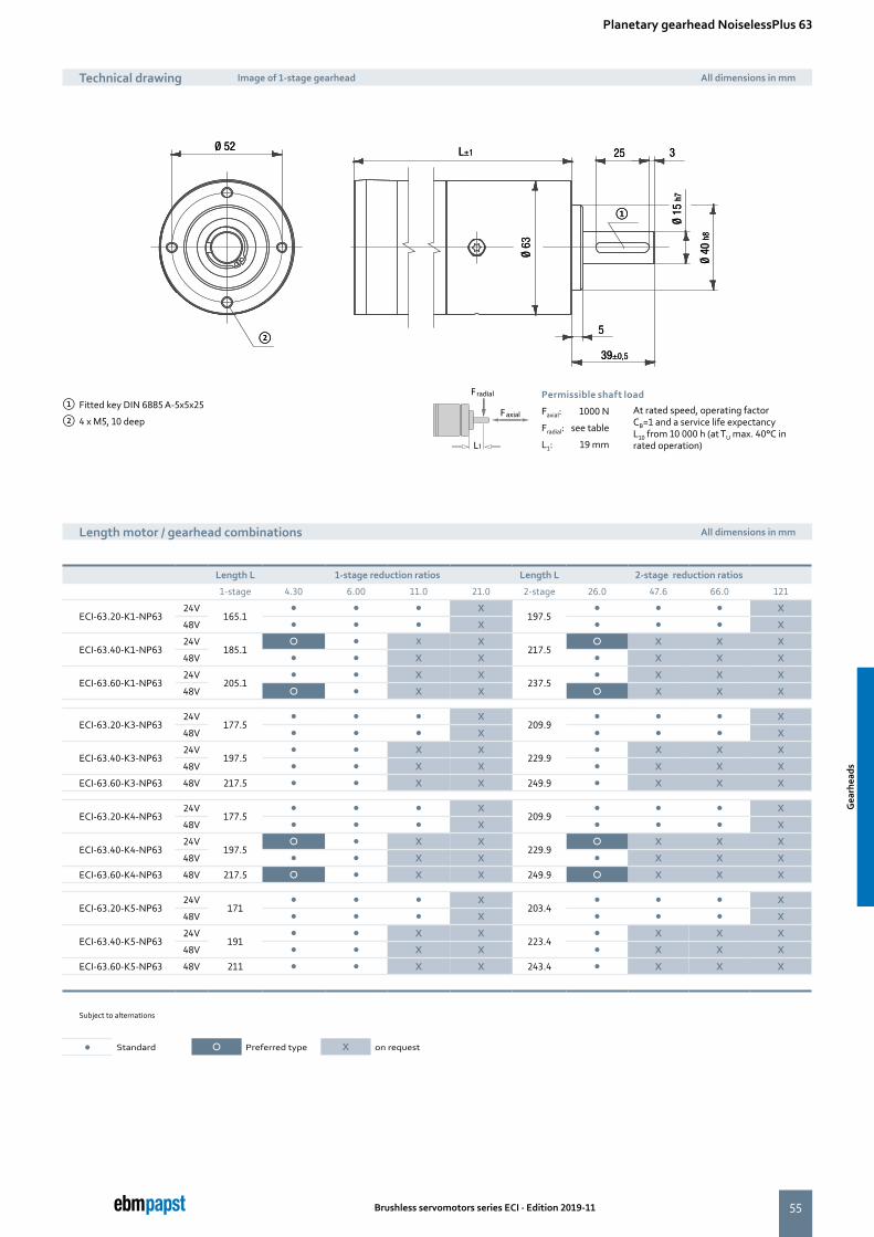
55
Ø 52 L±1
Ø 63
5
39±0,5
25 3
Ø 15
h7
Ø 40
h8
①
②
Ø 52 L±1
Ø 63
5
39±0,5
25 3
Ø 15
h7
Ø 40
h8
①
②
Brushless servomotors series ECI · Edition 2019-11
Planetary gearhead NoiselessPlus 63
Length motor / gearhead combinations All dimensions in mm
① Fitted key DIN 6885 A-5x5x25
② 4 x M5, 10 deepFaxial
Fradial
L1
Permissible shaft load
Faxial: 1000 N At rated speed, operating factor CB=1 and a service life expectancy L10 from 10 000 h (at TU max. 40°C in rated operation)
Fradial: see table
L1: 19 mm
Length L 1-stage reduction ratios Length L 2-stage reduction ratios
1-stage 4.30 6.00 11.0 21.0 2-stage 26.0 47.6 66.0 121
ECI-63.20-K1-NP6324V
165.1� � � X
197.5� � � X
48V � � � X � � � X
ECI-63.40-K1-NP6324V
185.1� � X X
217.5� X X X
48V � � X X � X X X
ECI-63.60-K1-NP6324V
205.1� � X X
237.5� X X X
48V � � X X � X X X
ECI-63.20-K3-NP6324V
177.5� � � X
209.9� � � X
48V � � � X � � � X
ECI-63.40-K3-NP6324V
197.5� � X X
229.9� X X X
48V � � X X � X X X
ECI-63.60-K3-NP63 48V 217.5 � � X X 249.9 � X X X
ECI-63.20-K4-NP6324V
177.5� � � X
209.9� � � X
48V � � � X � � � X
ECI-63.40-K4-NP6324V
197.5� � X X
229.9� X X X
48V � � X X � X X X
ECI-63.60-K4-NP63 48V 217.5 � � X X 249.9 � X X X
ECI-63.20-K5-NP6324V
171� � � X
203.4� � � X
48V � � � X � � � X
ECI-63.40-K5-NP6324V
191� � X X
223.4� X X X
48V � � X X � X X X
ECI-63.60-K5-NP63 48V 211 � � X X 243.4 � X X X
Subject to alternations
Technical drawing Image of 1-stage gearhead All dimensions in mm
� Standard � Preferred type X on request
Gea
rhea
ds
Gea
rhea
ds

56 Brushless servomotors series ECI · Edition 2019-11
Planetary gearhead Performax®Plus 42
Description
■ High torques thanks to large gearing width in the first gear stage
■ Good shock resistance due to housing made of case-hardened steel with linear tooth profile in the output stage
■ Very quiet operation due to helical teeth in the first gear stage
■ Planetary wheels made of plastic with op-timized sliding properties in the first stage ensure smooth operation
■ Large effective diameter thanks to radial screw connection
More at www.ebmpapst.com/eci-motoren
Image of 2-stage gearhead
Type Performax®Plus 42.1 Performax®Plus 42.2
Reduction ratio 5.00 9.00 30.0 54.0
No. of stages 1 1 2 2
Efficiency 0.90 0.90 0.81 0.81
Max. input speed (n1) rpm 6 000
Rated output torque (Mab) Nm 2.00 1.12 4.48 6.70
Short term torque (Mmax) Nm 5.00 2.80 11.2 16.8
Gear play ° 0.7 ... 1.2
Permissible operating temperature range °C -20 ... +80
Operating mode S1
Protection class IP 50
Weight kg 0.22 0.22 0.33 0.33
Shaft load radial / axial N 250 / 150
Service life h 5 000
Lubrication Maintenance free grease lubrication for life
Installation position any
Length mm 39.3 39.3 54.8 54.8
Subject to alternations
Gea
rhea
ds
Gea
rhea
ds
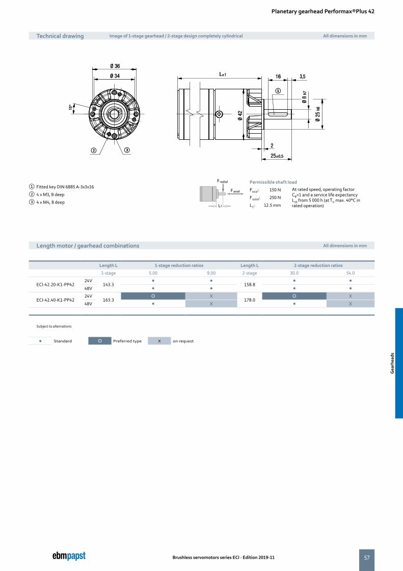
57
①
② ③
①
② ③
Brushless servomotors series ECI · Edition 2019-11
Planetary gearhead Performax®Plus 42
Length motor / gearhead combinations All dimensions in mm
① Fitted key DIN 6885 A-3x3x16
② 4 x M3, 8 deep
③ 4 x M4, 8 deep
Faxial
Fradial
L1
Permissible shaft load
Faxial: 150 N At rated speed, operating factor CB=1 and a service life expectancy L10 from 5 000 h (at TU max. 40°C in rated operation)
Fradial: 250 N
L1: 12.5 mm
Length L 1-stage reduction ratios Length L 2-stage reduction ratios
1-stage 5.00 9.00 2-stage 30.0 54.0
ECI-42.20-K1-PP4224V
143.3� �
158.8� �
48V � � � �
ECI-42.40-K1-PP4224V
163.3� X
178.0� X
48V � X � X
Subject to alternations
Technical drawing Image of 1-stage gearhead / 2-stage design completely cylindrical All dimensions in mm
� Standard � Preferred type X on request
Gea
rhea
ds
Gea
rhea
ds

58 Brushless servomotors series ECI · Edition 2019-11
Planetary gearhead Performax®Plus 63
Description
■ High torques thanks to large gearing width in the first gear stage
■ Good shock resistance due to housing made of case-hardened steel with linear tooth profile in the output stage
■ Very quiet running due to helical teeth in the first gear stage
■ Planetary wheels made of plastic with op-timized sliding properties in the first stage ensure smooth operation
■ Large effective diameter thanks to radial screw connection
More at www.ebmpapst.com/eci-motoren
Image of 2-stage gearhead
Type Performax®Plus 63.1 Performax®Plus 63.2
Reduction ratio 3.20 5.00 9.00 17.0 21.3 30.0 38.3 54.0 72.3 102 204
No. of stages 1 1 1 1 2 2 2 2 2 2 2
Efficiency 0.90 0.90 0.90 0.90 0.81 0.81 0.81 0.81 0.81 0.81 0.81
Max. input speed (n1) rpm 6 000
Rated output torque (Mab) Nm 6.50 11.9 7.60 4.40 45.2 64.0 28.9 41.0 16.9 23.9 27.4
Short term torque (Mmax) Nm 16.3 29.8 19.0 11.0 113 160 72.3 102.5 42.3 59.8 68.5
Gear play ° 0.7 ... 1.2
Permissible operating temperature range °C -20 ... +80
Operating mode S1
Protection class IP 50
Weight kg 0.66 0.66 0.66 0.66 1.20 1.20 1.20 1.20 1.20 1.20 1.20
Shaft load radial / axial N 350 / 500
Service life h 5 000
Lubrication Maintenance free grease lubrication for life
Installation position any
Length mm 57.7 57.7 57.7 57.7 79.1 79.1 79.1 79.1 79.1 79.1 79.1
Subject to alternations
Gea
rhea
ds
Gea
rhea
ds
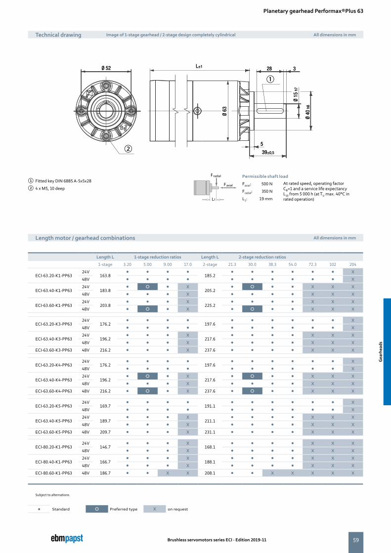
59
L±1 Ø 52
Ø 63
5
39±0,5
28 3
Ø 15
h7
Ø 40
h8
①
②
L±1 Ø 52
Ø 63
5
39±0,5
28 3
Ø 15
h7
Ø 40
h8
①
②
Brushless servomotors series ECI · Edition 2019-11
Planetary gearhead Performax®Plus 63
Length motor / gearhead combinations All dimensions in mm
① Fitted key DIN 6885 A-5x5x28
② 4 x M5, 10 deepFaxial
Fradial
L1
Permissible shaft load
Faxial: 500 N At rated speed, operating factor CB=1 and a service life expectancy L10 from 5 000 h (at TU max. 40°C in rated operation)
Fradial: 350 N
L1: 19 mm
Length L 1-stage reduction ratios Length L 2-stage reduction ratios
1-stage 3.20 5.00 9.00 17.0 2-stage 21.3 30.0 38.3 54.0 72.3 102 204
ECI-63.20-K1-PP6324V
163.8� � � �
185.2� � � � � � X
48V � � � � � � � � � � X
ECI-63.40-K1-PP6324V
183.8� � � X
205.2� � � � X X X
48V � � � X � � � � X X X
ECI-63.60-K1-PP6324V
203.8� � � X
225.2� � � � X X X
48V � � � X � � � � X X X
ECI-63.20-K3-PP6324V
176.2� � � �
197.6� � � � � � X
48V � � � � � � � � � � X
ECI-63.40-K3-PP6324V
196.2� � � X
217.6� � � � X X X
48V � � � X � � � � X X X
ECI-63.60-K3-PP63 48V 216.2 � � � X 237.6 � � � � X X X
ECI-63.20-K4-PP6324V
176.2� � � �
197.6� � � � � � X
48V � � � � � � � � � � X
ECI-63.40-K4-PP6324V
196.2� � � X
217.6� � � � X X X
48V � � � X � � � � X X X
ECI-63.60-K4-PP63 48V 216.2 � � � X 237.6 � � � � X X X
ECI-63.20-K5-PP6324V
169.7� � � �
191.1� � � � � � X
48V � � � � � � � � � � X
ECI-63.40-K5-PP6324V
189.7� � � X
211.1� � � � X X X
48V � � � X � � � � X X X
ECI-63.60-K5-PP63 48V 209.7 � � � X 231.1 � � � � X X X
ECI-80.20-K1-PP6324V
146.7� � � X
168.1� � � � X X X
48V � � � X � � � � X X X
ECI-80.40-K1-PP6324V
166.7� � � X
188.1� � � � X X X
48V � � � X � � � � X X X
ECI-80.60-K1-PP63 48V 186.7 � � X X 208.1 � � X X X X X
Subject to alternations
Technical drawing Image of 1-stage gearhead / 2-stage design completely cylindrical All dimensions in mm
� Standard � Preferred type X on request
Gea
rhea
ds
Gea
rhea
ds
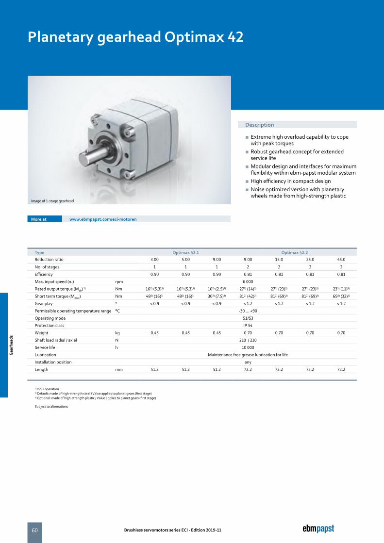
60 Brushless servomotors series ECI · Edition 2019-11
Planetary gearhead Optimax 42
Description
■ Extreme high overload capability to cope with peak torques
■ Robust gearhead concept for extended service life
■ Modular design and interfaces for maximum flexibility within ebm-papst modular system
■ High efficiency in compact design ■ Noise optimized version with planetary wheels made from high-strength plastic
More at www.ebmpapst.com/eci-motoren
Image of 1-stage gearhead
Type Optimax 42.1 Optimax 42.2
Reduction ratio 3.00 5.00 9.00 9.00 15.0 25.0 45.0
No. of stages 1 1 1 2 2 2 2
Efficiency 0.90 0.90 0.90 0.81 0.81 0.81 0.81
Max. input speed (n1) rpm 6 000
Rated output torque (Mab) 1) Nm 162) (5.3)3) 162) (5.3)3) 102) (2.5)3) 272) (14)3) 272) (23)3) 272) (23)3) 232) (11)3)
Short term torque (Mmax) Nm 482) (16)3) 482) (16)3) 302) (7.5)3) 812) (42)3) 812) (69)3) 812) (69)3) 692) (32)3)
Gear play ° < 0.9 < 0.9 < 0.9 < 1.2 < 1.2 < 1.2 < 1.2
Permissible operating temperature range °C -30 ... +90
Operating mode S1/S3
Protection class IP 54
Weight kg 0.45 0.45 0.45 0.70 0.70 0.70 0.70
Shaft load radial / axial N 210 / 210
Service life h 10 000
Lubrication Maintenance free grease lubrication for life
Installation position any
Length mm 51.2 51.2 51.2 72.2 72.2 72.2 72.2
1) In S1 operation2) Default: made of high-strength steel / Value applies to planet gears (first stage) 3) Optional: made of high-strength plastic / Value applies to planet gears (first stage)
Subject to alternations
Gea
rhea
ds
Gea
rhea
ds
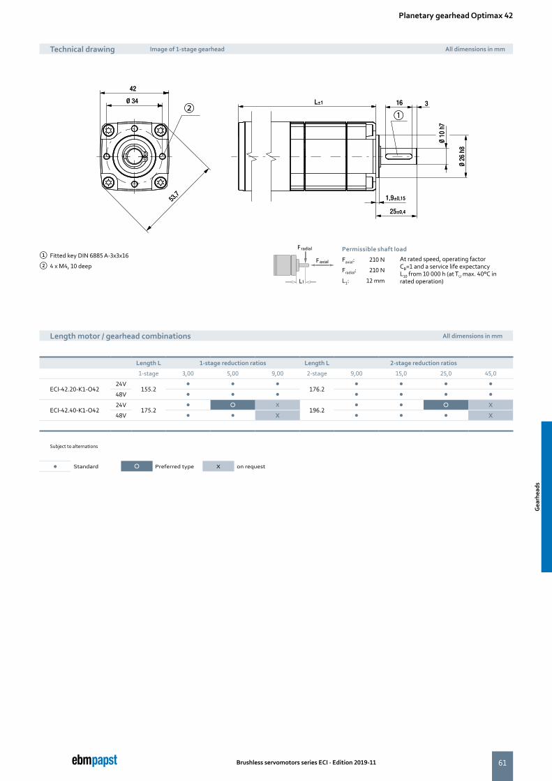
61
L±1 16 3
1,9±0,15
25±0,4
Ø 26
h8
Ø 10
h7
Ø 34
42
53,7
② ① L±1 16 3
1,9±0,15
25±0,4
Ø 26
h8
Ø 10
h7
Ø 34
42
53,7
② ①
Brushless servomotors series ECI · Edition 2019-11
Planetary gearhead Optimax 42
Length motor / gearhead combinations All dimensions in mm
① Fitted key DIN 6885 A-3x3x16
② 4 x M4, 10 deepFaxial
Fradial
L1
Permissible shaft load
Faxial: 210 N At rated speed, operating factor CB=1 and a service life expectancy L10 from 10 000 h (at TU max. 40°C in rated operation)
Fradial: 210 N
L1: 12 mm
Length L 1-stage reduction ratios Length L 2-stage reduction ratios
1-stage 3,00 5,00 9,00 2-stage 9,00 15,0 25,0 45,0
ECI-42.20-K1-O4224V
155.2� � �
176.2� � � �
48V � � � � � � �
ECI-42.40-K1-O4224V
175.2� � X
196.2� � � X
48V � � X � � � X
Subject to alternations
Technical drawing Image of 1-stage gearhead All dimensions in mm
� Standard � Preferred type X on request
Gea
rhea
ds
Gea
rhea
ds
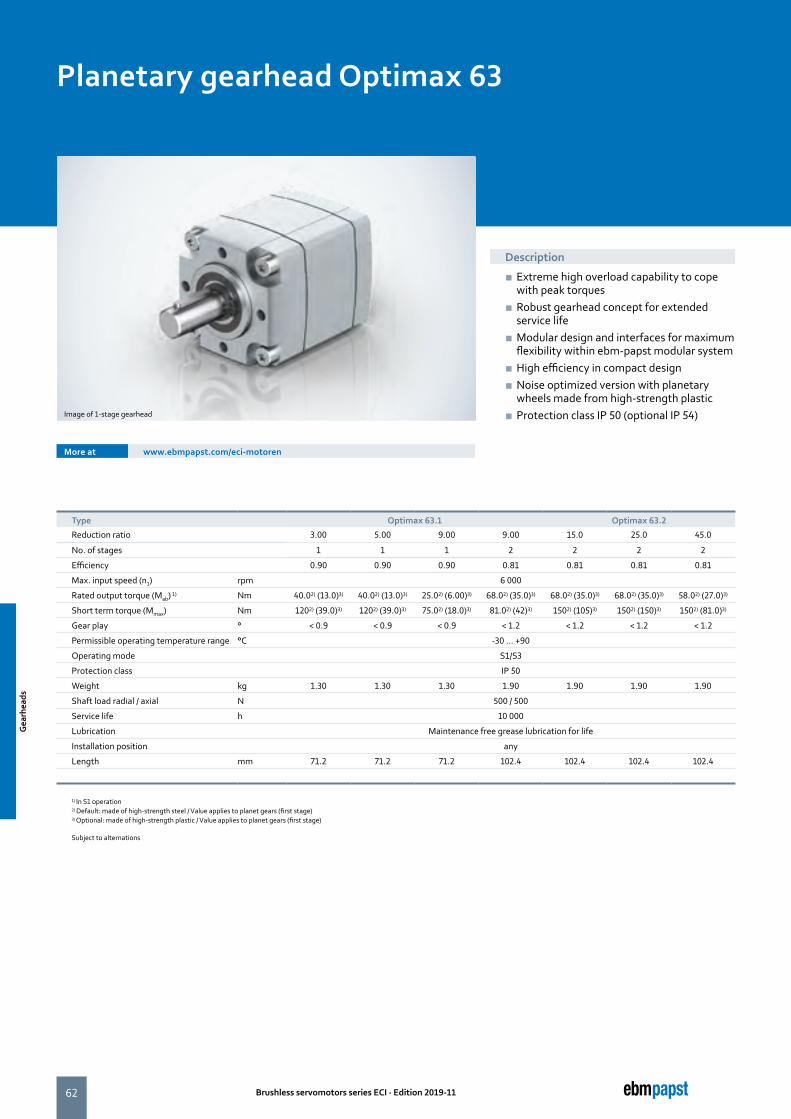
62 Brushless servomotors series ECI · Edition 2019-11
Planetary gearhead Optimax 63
Description
■ Extreme high overload capability to cope with peak torques
■ Robust gearhead concept for extended service life
■ Modular design and interfaces for maximum flexibility within ebm-papst modular system
■ High efficiency in compact design ■ Noise optimized version with planetary wheels made from high-strength plastic
■ Protection class IP 50 (optional IP 54)
More at www.ebmpapst.com/eci-motoren
Image of 1-stage gearhead
Type Optimax 63.1 Optimax 63.2
Reduction ratio 3.00 5.00 9.00 9.00 15.0 25.0 45.0
No. of stages 1 1 1 2 2 2 2
Efficiency 0.90 0.90 0.90 0.81 0.81 0.81 0.81
Max. input speed (n1) rpm 6 000
Rated output torque (Mab) 1) Nm 40.02) (13.0)3) 40.02) (13.0)3) 25.02) (6.00)3) 68.02) (35.0)3) 68.02) (35.0)3) 68.02) (35.0)3) 58.02) (27.0)3)
Short term torque (Mmax) Nm 1202) (39.0)3) 1202) (39.0)3) 75.02) (18.0)3) 81.02) (42)3) 1502) (105)3) 1502) (150)3) 1502) (81.0)3)
Gear play ° < 0.9 < 0.9 < 0.9 < 1.2 < 1.2 < 1.2 < 1.2
Permissible operating temperature range °C -30 ... +90
Operating mode S1/S3
Protection class IP 50
Weight kg 1.30 1.30 1.30 1.90 1.90 1.90 1.90
Shaft load radial / axial N 500 / 500
Service life h 10 000
Lubrication Maintenance free grease lubrication for life
Installation position any
Length mm 71.2 71.2 71.2 102.4 102.4 102.4 102.4
1) In S1 operation2) Default: made of high-strength steel / Value applies to planet gears (first stage) 3) Optional: made of high-strength plastic / Value applies to planet gears (first stage)
Subject to alternations
Gea
rhea
ds
Gea
rhea
ds
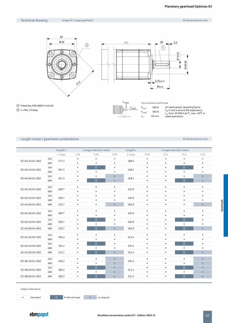
63
77,3
L±1
3,15±0,15
28 2,5
40±0,5
Ø 40
h8
Ø 15
h7
Ø 52
63
② ①
Brushless servomotors series ECI · Edition 2019-11
Planetary gearhead Optimax 63
Length motor / gearhead combinations All dimensions in mm
① Fitted key DIN 6885 A-5x5x28
② 4 x M4, 15 deepFaxial
Fradial
L1
Permissible shaft load
Faxial: 500 N At rated speed, operating factor CB=1 and a service life expectancy L10 from 10 000 h (at TU max. 40°C in rated operation)
Fradial: 500 N
L1: 20 mm
Technical drawing Image of 1-stage gearhead All dimensions in mm
Length L 1-stage reduction ratios Length L 2-stage reduction ratios
1-stage 3.00 5.00 9.00 2-stage 9.00 15.0 25.0 45.0
ECI-63.20-K1-O6324V
177.3� � �
208.5� � � �
48V � � � � � � �
ECI-63.40-K1-O6324V
197.3� � �
228.5� � � �
48V � � � � � � �
ECI-63.60-K1-O6324V
217.3� � X
248.5� � � X
48V � � X � � � X
ECI-63.20-K3-O6324V
189.7� � �
220.9� � � �
48V � � � � � � �
ECI-63.40-K3-O6324V
209.7� � �
240.9� � � �
48V � � � � � � �
ECI-63.60-K3-O63 48V 229.7 � � X 260.9 � � � X
ECI-63.60-K4-O6324V
189.7� � �
220.9� � � �
48V � � � � � � �
ECI-63.40-K4-O6324V
209.7� � �
240.9� � � �
48V � � � � � � �
ECI-63.60-K4-O63 48V 229.7 � � X 260.9 � � � X
ECI-63.20-K5-O6324V
183.2� � �
214.4� � � �
48V � � � � � � �
ECI-63.40-K5-O6324V
203.2� � �
234.4� � � �
48V � � � � � � �
ECI-63.60-K5-O63 48V 223.2 � � X 254.4 � � � X
ECI-80.20-K1-O6324V
160.2� � X
191.4� � � X
48V � � X � � � X
ECI-80.40-K1-O6324V
180.2� � X
211.4� � � X
48V � � X � � � X
ECI-80.60-K1-O63 48V 200.2 � � X 231.4 � � � X
Subject to alternations
� Standard � Preferred type X on request
Gea
rhea
ds
Gea
rhea
ds
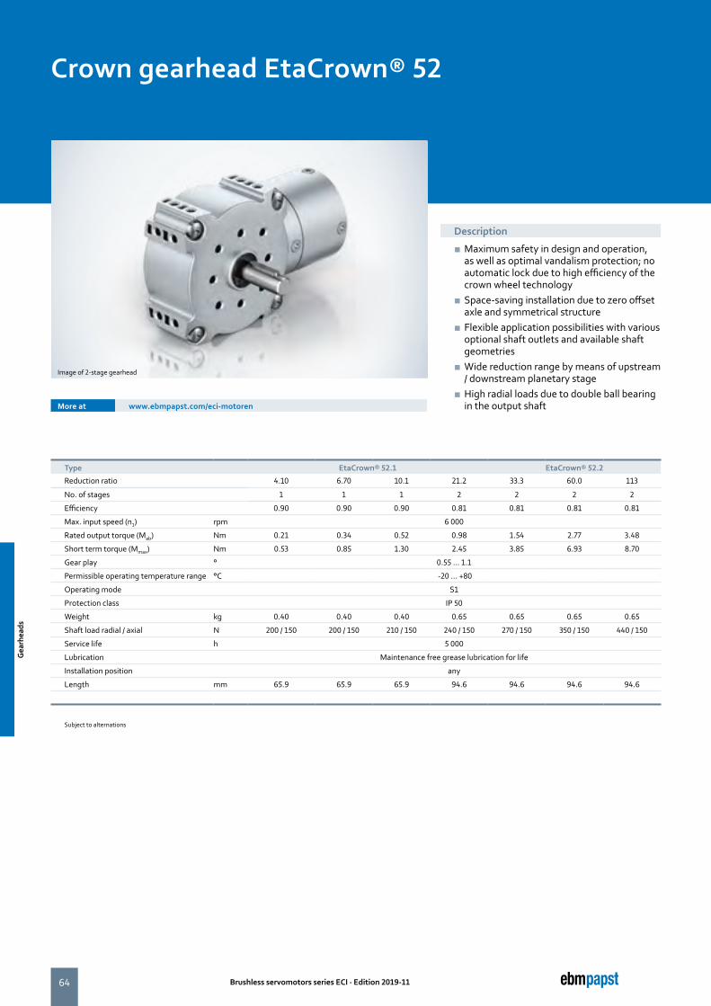
64 Brushless servomotors series ECI · Edition 2019-11
Crown gearhead EtaCrown® 52
Description
■ Maximum safety in design and operation, as well as optimal vandalism protection; no automatic lock due to high efficiency of the crown wheel technology
■ Space-saving installation due to zero offset axle and symmetrical structure
■ Flexible application possibilities with various optional shaft outlets and available shaft geometries
■ Wide reduction range by means of upstream / downstream planetary stage
■ High radial loads due to double ball bearing in the output shaftMore at www.ebmpapst.com/eci-motoren
Image of 2-stage gearhead
Type EtaCrown® 52.1 EtaCrown® 52.2
Reduction ratio 4.10 6.70 10.1 21.2 33.3 60.0 113
No. of stages 1 1 1 2 2 2 2
Efficiency 0.90 0.90 0.90 0.81 0.81 0.81 0.81
Max. input speed (n1) rpm 6 000
Rated output torque (Mab) Nm 0.21 0.34 0.52 0.98 1.54 2.77 3.48
Short term torque (Mmax) Nm 0.53 0.85 1.30 2.45 3.85 6.93 8.70
Gear play ° 0.55 ... 1.1
Permissible operating temperature range °C -20 ... +80
Operating mode S1
Protection class IP 50
Weight kg 0.40 0.40 0.40 0.65 0.65 0.65 0.65
Shaft load radial / axial N 200 / 150 200 / 150 210 / 150 240 / 150 270 / 150 350 / 150 440 / 150
Service life h 5 000
Lubrication Maintenance free grease lubrication for life
Installation position any
Length mm 65.9 65.9 65.9 94.6 94.6 94.6 94.6
Subject to alternations
Gea
rhea
ds
Gea
rhea
ds

65
L±1
38 58
25 ±0.3
10
2+0-0,2
30
Ø18
h8
2+0-0,2
228
Ø8
h7
16
3,5
Ø 36
Ø 32
29
Ø 42
①
② ③④
⑤
⑥
L±1
38 58
25 ±0.3
10
2+0-0,2
30
Ø18
h8
2+0-0,2
228
Ø8
h7
16
3,5
Ø 36
Ø 32
29
Ø 42
①
② ③④
⑤
⑥
Brushless servomotors series ECI · Edition 2019-11
Crown gearhead EtaCrown® 52
Length motor / gearhead combinations All dimensions in mm
① Fitted key DIN 6885 A-3x3x16
② 4 x M4, 6.5 deep (on all front faces)
③ 8 x M4, 6.5 deep (both sides)
④ Without hole at the opposite side
⑤ Motor centre point
⑥ Preferred direction of load
Faxial
Fradial
L1
Permissible shaft load
Faxial: 150 N At rated speed, operating factor CB=1 and a service life expectancy L10 from 5 000 h (at TU max. 40°C in rated operation)
Fradial: see table
L1: 12.5 mm
Technical drawing Image of 1-stage gearhead with right shaft end (W05) All dimensions in mm
Length L 1-stage reduction ratios Length L 2-stage reduction ratios
1-stage 4.10 6.70 10.1 2-stage 21.2 33.3 60.0 113
ECI-42.20-K1-E5224V
169.9� X X
198.6� � X X
48V � X X � � X X
ECI-42.40-K1-E5224V
189.9X X X
218.6X X X X
48V X X X X X X X
Subject to alternations
� Standard � Preferred type X on request
Shaft end, right (W05) (standard) Shaft end, left (W06) Shaft end, both sides (W07)
① Preferred direction of load
------>
①
------>
①
------>
①
Gea
rhea
ds
Gea
rhea
ds
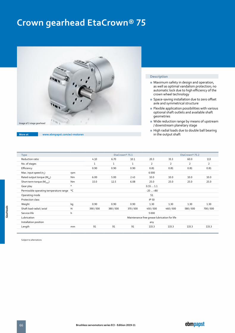
66 Brushless servomotors series ECI · Edition 2019-11
Crown gearhead EtaCrown® 75
Description
■ Maximum safety in design and operation, as well as optimal vandalism protection; no automatic lock due to high efficiency of the crown wheel technology
■ Space-saving installation due to zero offset axle and symmetrical structure
■ Flexible application possibilities with various optional shaft outlets and available shaft geometries
■ Wide reduction range by means of upstream / downstream planetary stage
■ High radial loads due to double ball bearing in the output shaftMore at www.ebmpapst.com/eci-motoren
Image of 2-stage gearhead
Type EtaCrown® 75.1 EtaCrown® 75.2
Reduction ratio 4.10 6.70 10.1 20.3 33.3 60.0 113
No. of stages 1 1 1 2 2 2 2
Efficiency 0.90 0.90 0.90 0.81 0.81 0.81 0.81
Max. input speed (n1) rpm 6 000
Rated output torque (Mab) Nm 6.00 5.00 2.43 10.0 10.0 10.0 10.0
Short term torque (Mmax) Nm 15.0 12.5 6.08 25.0 25.0 25.0 25.0
Gear play ° 0.55 ... 1.1
Permissible operating temperature range °C -20 ... +80
Operating mode S1
Protection class IP 50
Weight kg 0.90 0.90 0.90 1.30 1.30 1.30 1.30
Shaft load radial / axial N 390 / 500 380 / 500 370 / 500 450 / 500 460 / 500 580 / 500 700 / 500
Service life h 5 000
Lubrication Maintenance free grease lubrication for life
Installation position any
Length mm 91 91 91 133.3 133.3 133.3 133.3
Subject to alternations
Gea
rhea
ds
Gea
rhea
ds
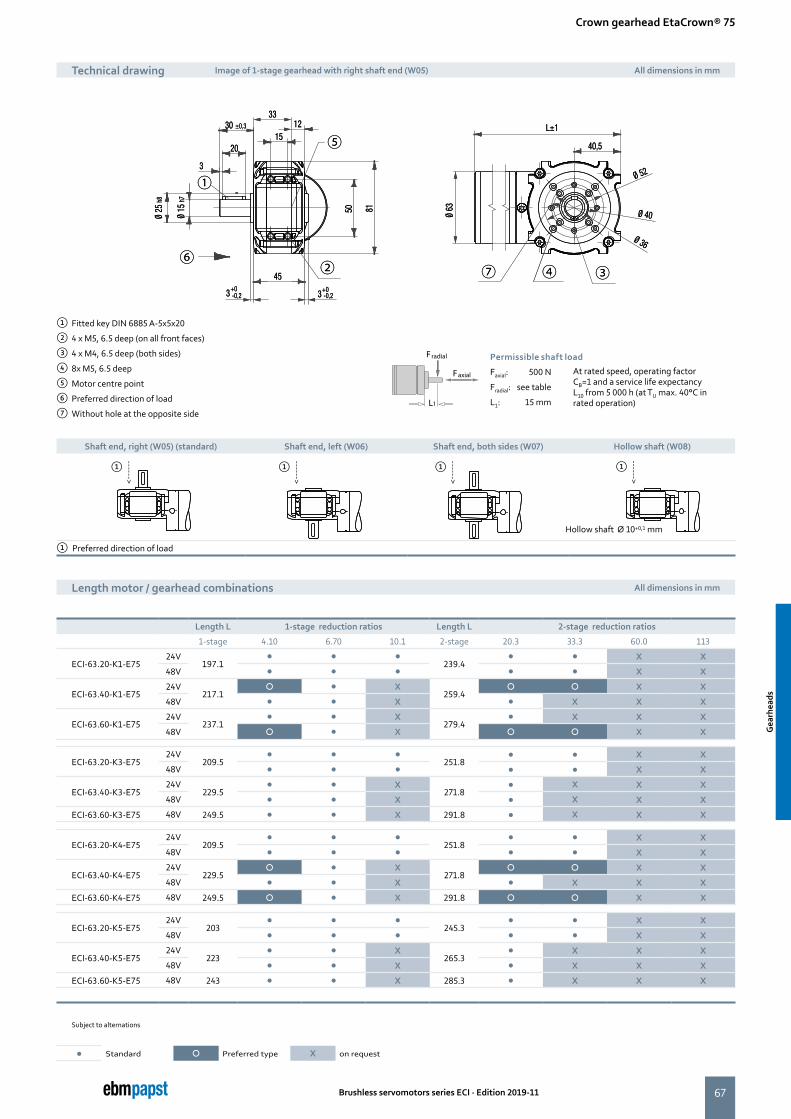
67
40,5
L±1
Ø 52
Ø 40
Ø 36
45
3+0-0,2 3+0
-0,2
15
331230 ±0,3
3
20
Ø 15
h7
Ø 25
h8
50 81 Ø 63
①
② ③④
⑤
⑥⑦
40,5
L±1
Ø 52
Ø 40
Ø 36
45
3+0-0,2 3+0
-0,2
15
331230 ±0,3
3
20
Ø 15
h7
Ø 25
h8
50 81 Ø 63
①
② ③④
⑤
⑥⑦
Brushless servomotors series ECI · Edition 2019-11
Shaft end, right (W05) (standard) Shaft end, left (W06) Shaft end, both sides (W07) Hollow shaft (W08)
Crown gearhead EtaCrown® 75
Length motor / gearhead combinations All dimensions in mm
① Fitted key DIN 6885 A-5x5x20
② 4 x M5, 6.5 deep (on all front faces)
③ 4 x M4, 6.5 deep (both sides)
④ 8x M5, 6.5 deep
⑤ Motor centre point
⑥ Preferred direction of load
⑦ Without hole at the opposite side
Faxial
Fradial
L1
Permissible shaft load
Faxial: 500 N At rated speed, operating factor CB=1 and a service life expectancy L10 from 5 000 h (at TU max. 40°C in rated operation)
Fradial: see table
L1: 15 mm
Technical drawing Image of 1-stage gearhead with right shaft end (W05) All dimensions in mm
Length L 1-stage reduction ratios Length L 2-stage reduction ratios
1-stage 4.10 6.70 10.1 2-stage 20.3 33.3 60.0 113
ECI-63.20-K1-E7524V
197.1� � �
239.4� � X X
48V � � � � � X X
ECI-63.40-K1-E7524V
217.1� � X
259.4� � X X
48V � � X � X X X
ECI-63.60-K1-E7524V
237.1� � X
279.4� X X X
48V � � X � � X X
ECI-63.20-K3-E7524V
209.5� � �
251.8� � X X
48V � � � � � X X
ECI-63.40-K3-E7524V
229.5� � X
271.8� X X X
48V � � X � X X X
ECI-63.60-K3-E75 48V 249.5 � � X 291.8 � X X X
ECI-63.20-K4-E7524V
209.5� � �
251.8� � X X
48V � � � � � X X
ECI-63.40-K4-E7524V
229.5� � X
271.8� � X X
48V � � X � X X X
ECI-63.60-K4-E75 48V 249.5 � � X 291.8 � � X X
ECI-63.20-K5-E7524V
203� � �
245.3� � X X
48V � � � � � X X
ECI-63.40-K5-E7524V
223� � X
265.3� X X X
48V � � X � X X X
ECI-63.60-K5-E75 48V 243 � � X 285.3 � X X X
Subject to alternations
� Standard � Preferred type X on request
Hollow shaft Ø 10+0,1 mm
① Preferred direction of load
------>
①
------>
①
------>
①
------>
①
Gea
rhea
ds
Gea
rhea
ds
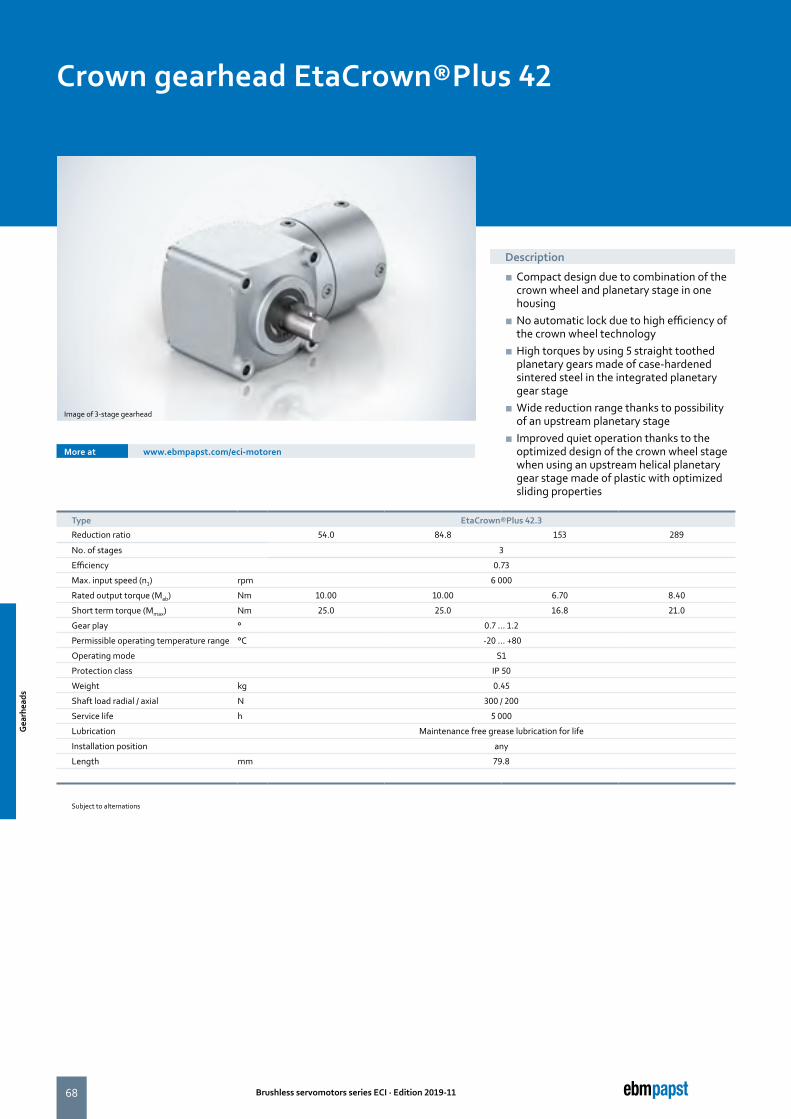
68 Brushless servomotors series ECI · Edition 2019-11
Crown gearhead EtaCrown®Plus 42
Description
■ Compact design due to combination of the crown wheel and planetary stage in one housing
■ No automatic lock due to high efficiency of the crown wheel technology
■ High torques by using 5 straight toothed planetary gears made of case-hardened sintered steel in the integrated planetary gear stage
■ Wide reduction range thanks to possibility of an upstream planetary stage
■ Improved quiet operation thanks to the optimized design of the crown wheel stage when using an upstream helical planetary gear stage made of plastic with optimized sliding properties
More at www.ebmpapst.com/eci-motoren
Image of 3-stage gearhead
Type EtaCrown®Plus 42.3
Reduction ratio 54.0 84.8 153 289
No. of stages 3
Efficiency 0.73
Max. input speed (n1) rpm 6 000
Rated output torque (Mab) Nm 10.00 10.00 6.70 8.40
Short term torque (Mmax) Nm 25.0 25.0 16.8 21.0
Gear play ° 0.7 ... 1.2
Permissible operating temperature range °C -20 ... +80
Operating mode S1
Protection class IP 50
Weight kg 0.45
Shaft load radial / axial N 300 / 200
Service life h 5 000
Lubrication Maintenance free grease lubrication for life
Installation position any
Length mm 79.8
Subject to alternations
Gea
rhea
ds
Gea
rhea
ds
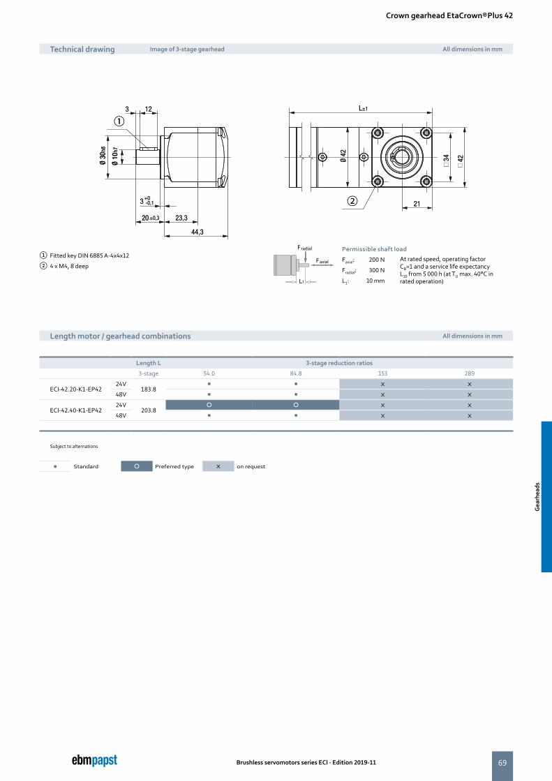
69
21
Ø 42
44,3
3+0-0,1
20 ±0,3 23,3
123
34 42
L±1Ø
30 h8
Ø 10
h7
O O
①
② 21
Ø 42
44,3
3+0-0,1
20 ±0,3 23,3
123
34 42
L±1Ø
30 h8
Ø 10
h7
O O
①
②
Brushless servomotors series ECI · Edition 2019-11
Crown gearhead EtaCrown®Plus 42
Technical drawing Image of 3-stage gearhead All dimensions in mm
Length motor / gearhead combinations All dimensions in mm
① Fitted key DIN 6885 A-4x4x12
② 4 x M4, 8 deepFaxial
Fradial
L1
Permissible shaft load
Faxial: 200 N At rated speed, operating factor CB=1 and a service life expectancy L10 from 5 000 h (at TU max. 40°C in rated operation)
Fradial: 300 N
L1: 10 mm
Length L 3-stage reduction ratios
3-stage 54.0 84.8 153 289
ECI-42.20-K1-EP4224V
183.8� � X X
48V � � X X
ECI-42.40-K1-EP4224V
203.8� � X X
48V � � X X
Subject to alternations
� Standard � Preferred type X on request
Gea
rhea
ds
Gea
rhea
ds
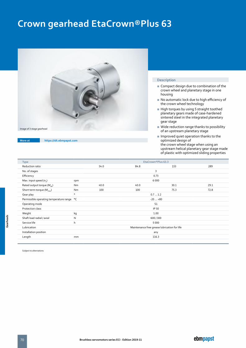
70 Brushless servomotors series ECI · Edition 2019-11
Crown gearhead EtaCrown®Plus 63
Description
■ Compact design due to combination of the crown wheel and planetary stage in one housing
■ No automatic lock due to high efficiency of the crown wheel technology
■ High torques by using 5 straight toothed planetary gears made of case-hardened sintered steel in the integrated planetary gear stage
■ Wide reduction range thanks to possibility of an upstream planetary stage
■ Improved quiet operation thanks to the optimized design of the crown wheel stage when using an upstream helical planetary gear stage made of plastic with optimized sliding properties
More at https://idt.ebmpapst.com
Image of 3-stage gearhead
Type EtaCrown®Plus 63.3
Reduction ratio 54.0 84.8 153 289
No. of stages 3
Efficiency 0.73
Max. input speed (n1) rpm 6 000
Rated output torque (Mab) Nm 40.0 40.0 30.1 29.1
Short term torque (Mmax) Nm 100 100 75.3 72.8
Gear play ° 0.7 ... 1.2
Permissible operating temperature range °C -20 ... +80
Operating mode S1
Protection class IP 50
Weight kg 1.00
Shaft load radial / axial N 600 / 300
Service life h 5 000
Lubrication Maintenance free grease lubrication for life
Installation position any
Length mm 116.3
Subject to alternations
Gea
rhea
ds
Gea
rhea
ds
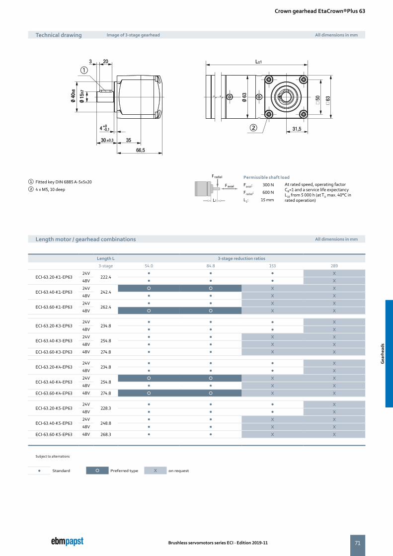
71
31,5
Ø 63
66,5
4+0-0,1
30 ±0,3 35
203
50 63
L±1
Ø 40
h8
Ø 15
h7
O O
①
② 31,5
Ø 63
66,5
4+0-0,1
30 ±0,3 35
203
50 63
L±1
Ø 40
h8
Ø 15
h7
O O
①
②
Brushless servomotors series ECI · Edition 2019-11
Crown gearhead EtaCrown®Plus 63
Technical drawing Image of 3-stage gearhead All dimensions in mm
Length motor / gearhead combinations All dimensions in mm
① Fitted key DIN 6885 A-5x5x20
② 4 x M5, 10 deepFaxial
Fradial
L1
Permissible shaft load
Faxial: 300 N At rated speed, operating factor CB=1 and a service life expectancy L10 from 5 000 h (at TU max. 40°C in rated operation)
Fradial: 600 N
L1: 15 mm
Length L 3-stage reduction ratios
3-stage 54.0 84.8 153 289
ECI-63.20-K1-EP6324V
222.4� � � X
48V � � � X
ECI-63.40-K1-EP6324V
242.4� � X X
48V � � X X
ECI-63.60-K1-EP6324V
262.4� � X X
48V � � X X
ECI-63.20-K3-EP6324V
234.8� � � X
48V � � � X
ECI-63.40-K3-EP6324V
254.8� � X X
48V � � X X
ECI-63.60-K3-EP63 48V 274.8 � � X X
ECI-63.20-K4-EP6324V
234.8� � � X
48V � � � X
ECI-63.40-K4-EP6324V
254.8� � X X
48V � � X X
ECI-63.60-K4-EP63 48V 274.8 � � X X
ECI-63.20-K5-EP6324V
228.3� � � X
48V � � � X
ECI-63.40-K5-EP6324V
248.8� � X X
48V � � X X
ECI-63.60-K5-EP63 48V 268.3 � � X X
Subject to alternations
� Standard � Preferred type X on request
Gea
rhea
ds
Gea
rhea
ds
72 Brushless servomotors series ECI · Edition 2019-11
the engineer’s choice
73Brushless servomotors series ECI · Edition 2019-11
Page
Commissioning tools 74
Brakes 76
Magnetic encoder systems 78
Accessories
Acc
esso
ries
Acc
esso
ries
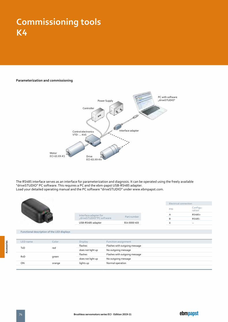
74 Brushless servomotors series ECI · Edition 2019-11
Parameterization and commissioning
The RS485 interface serves as an interface for parameterization and diagnosis. It can be operated using the freely available “driveSTUDIO” PC software. This requires a PC and the ebm-papst USB-RS485 adapter. Load your detailed operating manual and the PC software “driveSTUDIO” under www.ebmpapst.com.
PC with software „driveSTUDIO“Power Supply
Controller
Control electronicsVTD- ... K4S
Interface adapter
Motor ECI-63.XX-K1
Interface adapter for „driveSTUDIO“PC software Part number
USB-RS485-adapter 914 0000 403
Commissioning toolsK4
Functional description of the LED displays
LED name Color Display Function assignment
TxD redflashes Flashes with outgoing message
does not light up No outgoing message
RxD greenflashes Flashes with outgoing message
does not light up No outgoing message
ON orange lights up Normal operation
Drive ECI-63.XX-K4
Electrical connection
PIN Configu- ration
A RS485+
B RS485-
X --
Acc
esso
ries
Acc
esso
ries
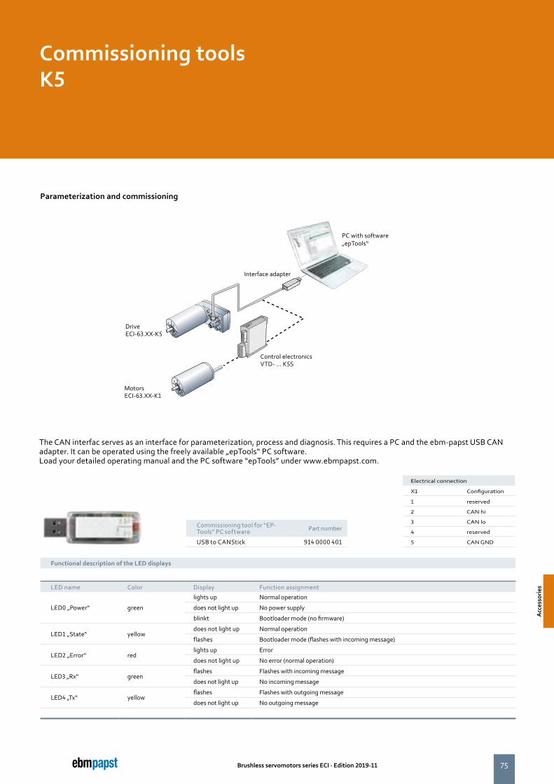
75Brushless servomotors series ECI · Edition 2019-11
Functional description of the LED displays
LED name Color Display Function assignment
LED0 „Power“ green
lights up Normal operation
does not light up No power supply
blinkt Bootloader mode (no firmware)
LED1 „State“ yellowdoes not light up Normal operation
flashes Bootloader mode (flashes with incoming message)
LED2 „Error“ redlights up Error
does not light up No error (normal operation)
LED3 „Rx“ greenflashes Flashes with incoming message
does not light up No incoming message
LED4 „Tx“ yellowflashes Flashes with outgoing message
does not light up No outgoing message
Commissioning tool for “EP-Tools” PC software Part number
USB to CANStick 914 0000 401
Parameterization and commissioning
PC with software „epTools“
Interface adapter
Motors ECI-63.XX-K1
Control electronicsVTD- ... K5S
DriveECI-63.XX-K5
Commissioning toolsK5
The CAN interfac serves as an interface for parameterization, process and diagnosis. This requires a PC and the ebm-papst USB CAN adapter. It can be operated using the freely available „epTools“ PC software. Load your detailed operating manual and the PC software “epTools” under www.ebmpapst.com.
Electrical connection
X1 Configuration
1 reserved
2 CAN hi
3 CAN lo
4 reserved
5 CAN GNDA
cces
sorie
s
Acc
esso
ries
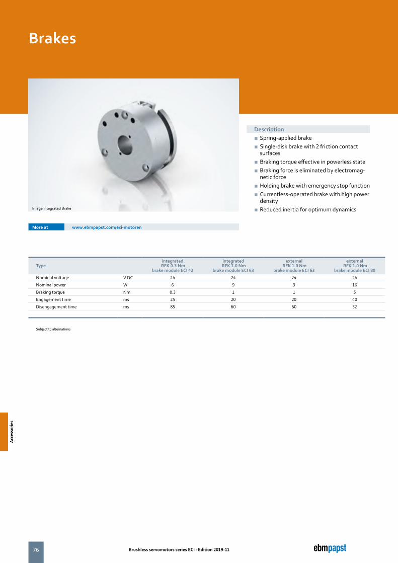
76 Brushless servomotors series ECI · Edition 2019-11
Description ■ Spring-applied brake ■ Single-disk brake with 2 friction contact surfaces
■ Braking torque effective in powerless state ■ Braking force is eliminated by electromag-netic force
■ Holding brake with emergency stop function ■ Currentless-operated brake with high power density
■ Reduced inertia for optimum dynamics
Typeintegrated
RFK 0.3 Nmbrake module ECI 42
integrated RFK 1.0 Nm
brake module ECI 63
external RFK 1.0 Nm
brake module ECI 63
external RFK 1.0 Nm
brake module ECI 80
Nominal voltage V DC 24 24 24 24
Nominal power W 6 9 9 16
Braking torque Nm 0.3 1 1 5
Engagement time ms 25 20 20 40
Disengagement time ms 85 60 60 52
Subject to alternations
Brakes
Image integrated Brake
More at www.ebmpapst.com/eci-motoren
Acc
esso
ries
Acc
esso
ries
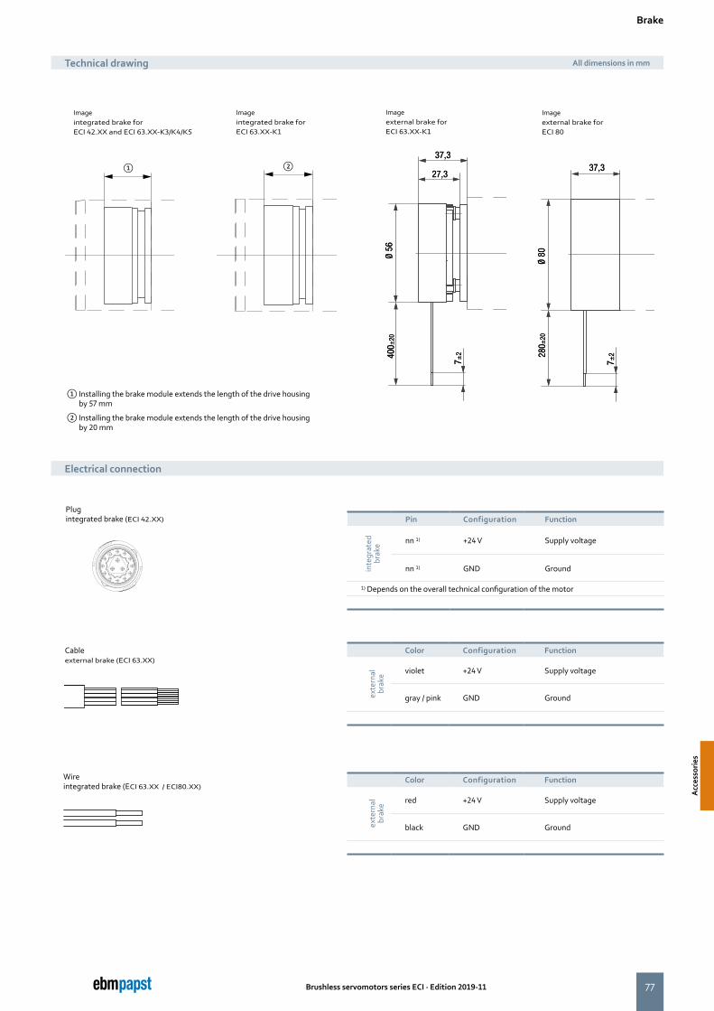
77
①
13
14
B
4 5
23
7
1
A
10
9
8
C
11
12
14
15
37,3
27,3
Ø 56
400±
20
280 ±
20
37,3
Ø 80
37,3
27,3
Ø 56
400±
20
280 ±
20
37,3
Ø 80
②
Brushless servomotors series ECI · Edition 2019-11
Electrical connection
Color Configuration Function
exte
rnal
br
ake red +24 V Supply voltage
black GND Ground
Pin Configuration Function
inte
grat
ed
brak
e nn 1) +24 V Supply voltage
nn 1) GND Ground
1) Depends on the overall technical configuration of the motor
Color Configuration Function
exte
rnal
br
ake violet +24 V Supply voltage
gray / pink GND Ground
Brake
Technical drawing All dimensions in mm
Image external brake for ECI 63.XX-K1
Imageexternal brake for ECI 80
Imageintegrated brake forECI 42.XX and ECI 63.XX-K3/K4/K5
① Installing the brake module extends the length of the drive housing by 57 mm
② Installing the brake module extends the length of the drive housing by 20 mm
Imageintegrated brake for ECI 63.XX-K1
Plugintegrated brake (ECI 42.XX)
Cableexternal brake (ECI 63.XX)
Wire integrated brake (ECI 63.XX / ECI80.XX)
Acc
esso
ries
Acc
esso
ries
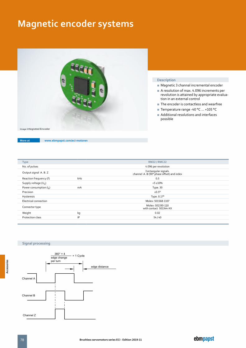
78 Brushless servomotors series ECI · Edition 2019-11
Magnetic encoder systems
Description ■ Magnetic 3 channal incremental encoder ■ A resolution of max. 4.096 increments per revolution is attained by appropriate evalua-tion in an external control
■ The encoder is contactless and wearfree ■ Temperature range -40 °C ... +105 °C ■ Additional resolutions and interfaces possible
Type RM22 / RMC22
No. of pulses 4.096 per revolution
Output signal A. B. Z 3 ectangular signals. channel A. B (90° phase offset) and index
Reaction frequency (f) kHz 0.5
Supply voltage (UB) +5 ±10%
Power consumption (IB) mA Type. 30
Precision ±0.5°
Hysteresis Type. 0.17°
Electrical connection Molex: 501568-1107
Connector type Molex: 501330-110 with contact 501344-XX
Weight kg 0.02
Protection class IP 54 / 40
Signal processing
More at www.ebmpapst.com/eci-motoren
Image integrated Encoder
Acc
esso
ries
Acc
esso
ries
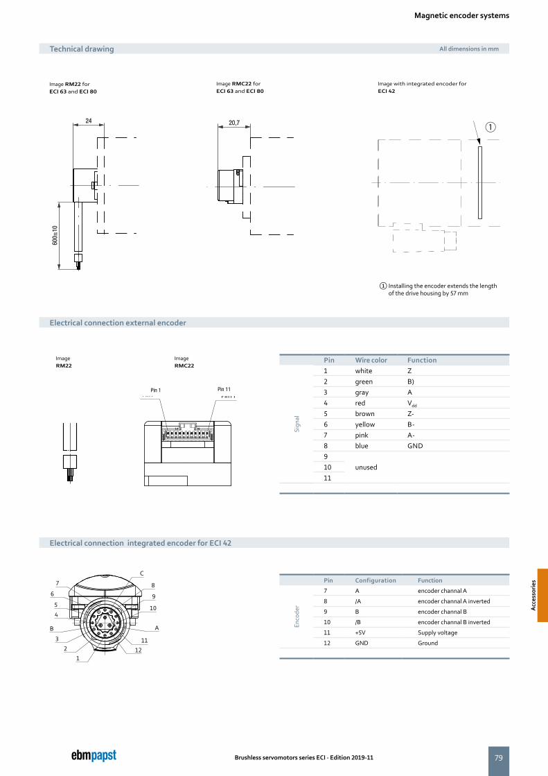
79
①
Pin11Pin1Pin 1 Pin 11
B
4
5
2
3
6
7
1
A
10
9
8
C
11
12
600±
10
L324
L4
20,7
600±
10
L324
L4
20,7
Brushless servomotors series ECI · Edition 2019-11
Pin Wire color Function
Sign
al
1 white Z2 green B)3 gray A4 red Vdd
5 brown Z-6 yellow B-7 pink A-8 blue GND9
unused1011
Electrical connection external encoder
Technical drawing All dimensions in mm
Pin Configuration Function
Enco
der
7 A encoder channal A
8 /A encoder channal A inverted
9 B encoder channal B
10 /B encoder channal B inverted
11 +5V Supply voltage
12 GND Ground
Image RM22 forECI 63 and ECI 80
Image with integrated encoder forECI 42
Image RMC22 forECI 63 and ECI 80
Electrical connection integrated encoder for ECI 42
Image RM22
Image RMC22
Magnetic encoder systems
① Installing the encoder extends the length of the drive housing by 57 mm
Acc
esso
ries
Acc
esso
ries
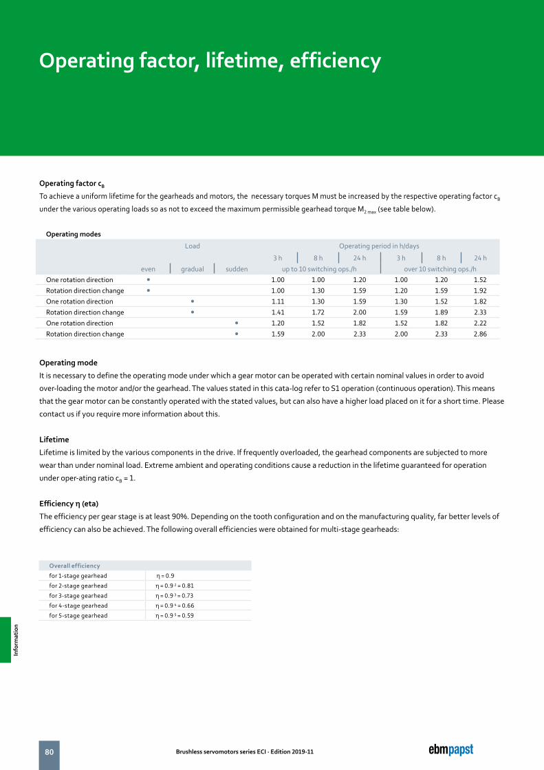
80 Brushless servomotors series ECI · Edition 2019-11
Operating factor cB
To achieve a uniform lifetime for the gearheads and motors, the necessary torques M must be increased by the respective operating factor cB
under the various operating loads so as not to exceed the maximum permissible gearhead torque M2 max (see table below).
Operating mode
It is necessary to define the operating mode under which a gear motor can be operated with certain nominal values in order to avoid
over-loading the motor and/or the gearhead. The values stated in this cata-log refer to S1 operation (continuous operation). This means
that the gear motor can be constantly operated with the stated values, but can also have a higher load placed on it for a short time. Please
contact us if you require more information about this.
Lifetime
Lifetime is limited by the various components in the drive. If frequently overloaded, the gearhead components are subjected to more
wear than under nominal load. Extreme ambient and operating conditions cause a reduction in the lifetime guaranteed for operation
under oper-ating ratio cB = 1.
Efficiency η (eta)
The efficiency per gear stage is at least 90%. Depending on the tooth configuration and on the manufacturing quality, far better levels of
efficiency can also be achieved. The following overall efficiencies were obtained for multi-stage gearheads:
Operating factor, lifetime, efficiency
Operating modes
Load Operating period in h/days
3 h 8 h 24 h 3 h 8 h 24 h
even gradual sudden up to 10 switching ops./h over 10 switching ops./hOne rotation direction � 1.00 1.00 1.20 1.00 1.20 1.52Rotation direction change � 1.00 1.30 1.59 1.20 1.59 1.92One rotation direction � 1.11 1.30 1.59 1.30 1.52 1.82Rotation direction change � 1.41 1.72 2.00 1.59 1.89 2.33One rotation direction � 1.20 1.52 1.82 1.52 1.82 2.22Rotation direction change � 1.59 2.00 2.33 2.00 2.33 2.86
Overall efficiency
for 1-stage gearhead η = 0.9
for 2-stage gearhead η = 0.9 2 = 0.81
for 3-stage gearhead η = 0.9 3 = 0.73
for 4-stage gearhead η = 0.9 4 = 0.66
for 5-stage gearhead η = 0.9 5 = 0.59
Info
rmat
ion

81Brushless servomotors series ECI · Edition 2019-11
Info
rmat
ion
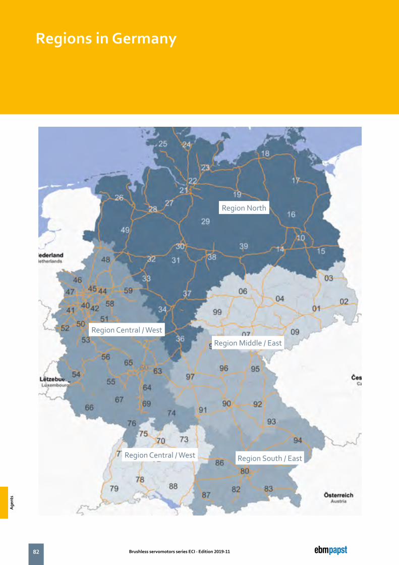
82 Brushless servomotors series ECI · Edition 2019-11
Regions in Germany
Region North
Region Middle / East
Region Central / West
Region South / EastRegion Central / West
Age
nts
Age
nts
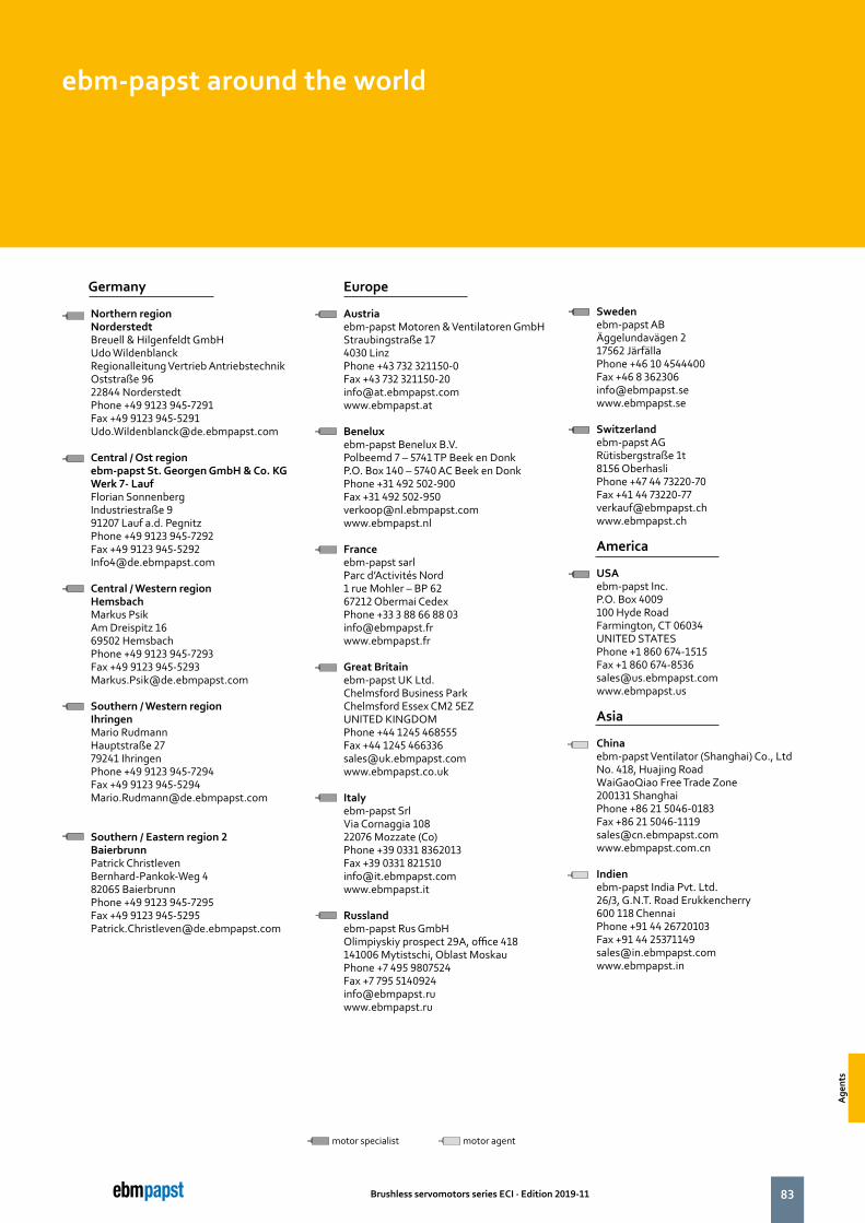
83Brushless servomotors series ECI · Edition 2019-11
ebm-papst around the world
motor specialist motor agent
Germany
Northern regionNorderstedtBreuell & Hilgenfeldt GmbHUdo Wildenblanck Regionalleitung Vertrieb AntriebstechnikOststraße 9622844 NorderstedtPhone +49 9123 945-7291Fax +49 9123 [email protected]
Central / Ost regionebm-papst St. Georgen GmbH & Co. KGWerk 7- LaufFlorian SonnenbergIndustriestraße 991207 Lauf a.d. PegnitzPhone +49 9123 945-7292Fax +49 9123 [email protected]
Central / Western regionHemsbachMarkus PsikAm Dreispitz 1669502 HemsbachPhone +49 9123 945-7293Fax +49 9123 [email protected]
Southern / Western regionIhringenMario RudmannHauptstraße 2779241 IhringenPhone +49 9123 945-7294Fax +49 9123 [email protected]
Southern / Eastern region 2BaierbrunnPatrick ChristlevenBernhard-Pankok-Weg 482065 BaierbrunnPhone +49 9123 945-7295Fax +49 9123 [email protected]
Europe
Austria ebm-papst Motoren & Ventilatoren GmbHStraubingstraße 174030 LinzPhone +43 732 321150-0Fax +43 732 [email protected]
Beneluxebm-papst Benelux B.V.Polbeemd 7 – 5741 TP Beek en DonkP.O. Box 140 – 5740 AC Beek en DonkPhone +31 492 502-900Fax +31 492 [email protected]
Franceebm-papst sarlParc d’Activités Nord1 rue Mohler – BP 6267212 Obermai CedexPhone +33 3 88 66 88 [email protected]
Great Britainebm-papst UK Ltd.Chelmsford Business ParkChelmsford Essex CM2 5EZUNITED KINGDOMPhone +44 1245 468555Fax +44 1245 [email protected]
Italyebm-papst SrlVia Cornaggia 10822076 Mozzate (Co)Phone +39 0331 8362013Fax +39 0331 [email protected]
Russlandebm-papst Rus GmbHOlimpiyskiy prospect 29A, office 418141006 Mytistschi, Oblast MoskauPhone +7 495 9807524Fax +7 795 [email protected]
Swedenebm-papst ABÄggelundavägen 217562 JärfällaPhone +46 10 4544400Fax +46 8 [email protected]
Switzerlandebm-papst AGRütisbergstraße 1t8156 OberhasliPhone +47 44 73220-70Fax +41 44 [email protected]
America
USAebm-papst Inc.P.O. Box 4009100 Hyde RoadFarmington, CT 06034UNITED STATESPhone +1 860 674-1515Fax +1 860 [email protected]
Asia
Chinaebm-papst Ventilator (Shanghai) Co., LtdNo. 418, Huajing RoadWaiGaoQiao Free Trade Zone200131 ShanghaiPhone +86 21 5046-0183Fax +86 21 [email protected] www.ebmpapst.com.cn
Indienebm-papst India Pvt. Ltd.26/3, G.N.T. Road Erukkencherry600 118 ChennaiPhone +91 44 26720103Fax +91 44 [email protected] www.ebmpapst.in
Age
nts
Age
nts
the engineer’s choice
ebm-papst St. Georgen
GmbH & Co. KG
Hauptverwaltung
Hermann-Papst-Straße 1
78112 St. Georgen
GERMANY
Phone +49 7724 81-0
Fax +49 7724 81-1309
ebm-papst St. Georgen
GmbH & Co. KG
Werk 7 Lauf
Industriestraße 9
91207 Lauf a. d. Pegnitz
GERMANY
Phone +49 9123 945-0
Fax +49 9123 945-145
www.ebmpapst.com 37965-7-8811 · 2019-11 · WA-1`Printed in Germany
FSC