Fuel Cell Based Grid Connected Boost Inverter Systemirphouse.com/ijeee/ijeeev8n1_02.pdf · Fuel...
14
International Journal of Electronic and Electrical Engineering. ISSN 0974-2174 Volume 8, Number 1 (2015), pp. 13-25 © International Research Publication House http://www.irphouse.com Fuel Cell Based Grid Connected Boost Inverter System N.Venkateswarlu 1 , Dr. L.V.Narasimharao 2 P.Ankineedu Prasad 3 , V.Ramesh 4 Assistant Professor 13 & Professor 2 & Research Scholar 4 K L University, Guntur, Andhra Pradesh India Email: [email protected] 1 , [email protected] 2 , [email protected] 3 , [email protected] 4 Abstract: The boost-inverter topology is used as a building block for a single-phase grid- connected fuel cell (FC) system, which is offering low cost and compactness. In addition to that, the proposed system incorporates battery-based energy storage and a dc–dc bidirectional converter (Back-up unit) to support the slow dynamics of the FC. The single-phase boost inverter is voltage-mode controlled and the dc–dc bidirectional converter is current-mode controlled. The low-frequency current ripple is supplied by the battery which minimizes the effects of such ripple being drawn directly from the FC itself. Moreover, this system can operate either in a grid-connected or stand-alone mode. In the grid-connected mode, the boost inverter is able to control the active (P) and reactive (Q) powers using an algorithm based on a second-order generalized integrator which provides a fast signal conditioning for single-phase systems. By using MATLAB/SIMULINK 2009a version, simulation was performed and, simulation results Key words: Boost-inverter, DC–DC bidirectional converter, Fuel cell, Grid 1. INTRODUCTION The centralized and regulated electric utilities have always been the major source of electric power production and supply. However, the increase in demand for electric power has led to the development of distributed generation (DG) which can complement the central power by providing additional capacity to the users. These are small generating units which can be located at the consumer end or anywhere within the distribution system.
Transcript of Fuel Cell Based Grid Connected Boost Inverter Systemirphouse.com/ijeee/ijeeev8n1_02.pdf · Fuel...

International Journal of Electronic and Electrical Engineering. ISSN 0974-2174 Volume 8, Number 1 (2015), pp. 13-25 © International Research Publication House http://www.irphouse.com
Fuel Cell Based Grid Connected Boost Inverter System
N.Venkateswarlu1, Dr. L.V.Narasimharao2 P.Ankineedu Prasad3, V.Ramesh4
Assistant Professor13 & Professor2 & Research Scholar4 K L University, Guntur, Andhra Pradesh India
Email: [email protected], [email protected], [email protected], [email protected]
Abstract:
The boost-inverter topology is used as a building block for a single-phase grid-connected fuel cell (FC) system, which is offering low cost and compactness. In addition to that, the proposed system incorporates battery-based energy storage and a dc–dc bidirectional converter (Back-up unit) to support the slow dynamics of the FC. The single-phase boost inverter is voltage-mode controlled and the dc–dc bidirectional converter is current-mode controlled. The low-frequency current ripple is supplied by the battery which minimizes the effects of such ripple being drawn directly from the FC itself. Moreover, this system can operate either in a grid-connected or stand-alone mode. In the grid-connected mode, the boost inverter is able to control the active (P) and reactive (Q) powers using an algorithm based on a second-order generalized integrator which provides a fast signal conditioning for single-phase systems. By using MATLAB/SIMULINK 2009a version, simulation was performed and, simulation results Key words: Boost-inverter, DC–DC bidirectional converter, Fuel cell, Grid
1. INTRODUCTION The centralized and regulated electric utilities have always been the major source of electric power production and supply. However, the increase in demand for electric power has led to the development of distributed generation (DG) which can complement the central power by providing additional capacity to the users. These are small generating units which can be located at the consumer end or anywhere within the distribution system.

14 N.Venkateswarlu et al
Fig 1. A large central power plant and Distributed generation systems
DG can be beneficial to the consumers as well as the utility. Consumers are interested in DG due to the various benefits associated with it: cost saving during peak demand charges, higher power quality and increased energy efficiency. The utilities can also benefit as it generallyeliminatesthecostneededforlayingnewtransmission/distributionlines.Distributed
Generation employs alternate resources such as micro-turbines, solar photovoltaic systems, fuel cells and wind energy systems. This thesis lays emphasis on the fuel cell technology and its integration with the utility grid. Recently, the use of distributed generation systems under the 500 kW level is rapidly increasing due to technology improvements in small generators, power electronics, and energy storage devices. Efficient clean fossil-fuels technologies such as micro-turbines, fuel cells, and environmental-friendly renewable energy technologies such as biomass, solar/photovoltaic arrays, small wind turbines and hydro turbines, are growingly used for new distributed generation systems. These DGS are applied to a standalone , a grid-interconnected, a standby, peak shavings , a cogeneration etc. and have a lot of benefits such as environmental-friendly and modular electric generation, increased reliability/stability, high power quality, load management, fuel flexibility, uninterruptible service, cost savings, on-site generation, expandability, etc. 2. Fuel cells These cells are also well used for distributed generation applications, and can essentially be described as batteries which never become discharged as long as hydrogen and oxygen are continuously provided. The hydrogen can be supplied directly, or indirectly produced by reformer from fuels such as natural gas, alcohols, or gasoline. Each unit ranges in size from 1-250 kW or larger MW size. Even if they offer high efficiency and low emissions, today's costs are high. Phosphoric acid fuel cell is commercially available in the range of the 200 kW, while solid oxide and molten carbonate fuel cells are in a pre-commercial stage of development. The possibility of using gasoline as a fuel for cells has resulted in a

Fuel Cell Based Grid Connected Boost Inverter System 15
major development effort by the automotive companies. The recent research work about the fuel cells is focused towards the polymer electrolyte membrane (PEM) fuel cells. Fuel cells in sizes greater than 200 kW, hold promise beyond 2005, but residential size fuel cells are unlikely to have any significant market impact any time soon. Figure 2 shows a block diagram of fuel cell system which consists of a reformer, fuel cell stack and a PCU. 2.1. Mixed micro-turbine and fuel cell systems These systems will also be available as a distributed generation source. Recently, a solid oxide fuel cell has been combined with a gas micro- turbine creating a combined cycle power plant. It has expected electrical efficiency of greater than 70 %, and the expected power levels range from 250 kW to 2.5 MW.
Fig 2. Block diagram of fuel cell system
2.2. Solar/photovoltaic systems These systems to transform sunlight into electricity are also a good renewable technology for DGS because sunlight is an abundant resource around the world and solar electric systems are clean, quiet and easy to use, and first of all no fuel other than sunlight is needed. Furthermore, they are durable, reliable, and easy to because they do not hold any moving parts. Solar cells, also known as photovoltaic (PV) cells, use special materials called semiconductors that produce electricity when exposed to light, and four promising types of solar electric technology are under development: crystalline silicon (a form of refined beach sand), thin films, concentrators, and thermo-photovoltaic’s. Photovoltaic arrays may be used in a variety of sizes from 0.3 kW to 2 MW. However, installing a large number of systems make this choice undesirable. This becomes apparent when the following factors are considered; 1) high cost of land, 2) poor solar intensity in many geographic areas, and 3) climates lacking reliable sun exposure. In general, almost one acre of land would be needed to provide 150 kW of electricity. Figure 1.5 describes a block diagram of solar/photovoltaic array system and its features are abstracted in the following.

16 N.Venkateswarlu et al
Fig3.Blockdiagramofsolar/photovoltaicarraysystem
A comparison of currently competitive DGS technologies mentioned above is given in Table 1. In the past, the electric utility industry did not offer suitable options that were suited for a wide range of consumer needs, and most utilities offered at best two or three combinations of reliability and price. However, the modern types of DGS give commercial electric consumers various options in a wider range of reliability-price combinations. For these reasons, the DGS will be very likely to thrive in the next 20 years in particular. Distributed generation technologies will have a much greater market potential in areas such as developing countries whose electricity costs are high and unreliable. Distributed Generation powered by micro-sources such as fuel cells, photovoltaic cells and micro-turbines, have been gaining popularity among the industry and utilities due to their higher operating efficiencies, improved reliabilities, and lower emission levels. The introduction of distributed generation to the distribution system has a significant impact on the flow of power and voltage conditions at the customers and utility equipment. Among the micro-source, fuel cells are attractive due to their modular, efficient, and environmentally friendly performance. Fuel cells are capable of operating at efficiencies greater than traditional energy production methods. Moreover, the scalability of fuel cells has allowed for applications in almost every field. Fuel cell systems can be easily placed at any site in a power system for grid reinforcement, thereby deferring or eliminating the need for system upgrades and improving system integrity, reliability, and efficiency.
Fig4. Block diagram for the proposed grid-connected FC system.
Fuel Cell Based Grid Connected Boost Inverter System 17
The objective of this paper is to propose and report full experimental results of a grid-connected single-phase FC system using a single energy conversion stage only. In particular, the proposed system, based on the boost inverter with a backup energy storage unit, solves the previously mentioned issues (e.g., the low and variable output voltage of the FC, its slow dynamics, and current harmonics on the FC side). The single energy conversion stage includes both boosting and inversion functions and provides high power conversion efficiency, reduced converter size, and low cost .The proposed single-phase grid-connected FC system can operate either in grid-connected or stand-alone mode. In the grid-connected mode, the boost inverter is able to control the active (P) and reactive (Q) powers through the grid by the proposed PQ control algorithm using fast signal conditioning for single-phase systems 3. Control of the grid connected boost inverter The equivalent circuit of the grid connected FC system consisting of two AC sources (Vg &Vo), an AC inductor Lf between two sources, and load. The boost inverter output including FC and backup unit is indicated as Vo and Vg is the grid voltage. The active and reactive powers are expressed as
(4.1)
(4.2)
Where Lf is the filterinductancebetweenthegridandthe boost inverter. From
equations, the phase shift δ and voltage difference Vg-Vo between Vo and affect the active and reactive powers, respectively. Therefore, to control the power flows between boost inverter and the grid, the FC system must be able to vary its output voltage Vo in amplitude and phase with respect to the grid voltage VgFig5. shows control of power between the grid and the boost inverter with different vector diagrams. According to those vector diagrams, power flow, active and reactive powers should be controlled by the phase angle and the inverter voltage amplitude, Vo For instance, when reactive power is zero, fig 5(a) shows active power controlling with small variations of δ and dVpp. If active and reactive powers need to be controlled simultaneously. Fig 5(b) is the approach to control them .Fig5(c) illustrates when active power reference is zero.

18 N.Venkateswarlu et al
Fig 5. Vector diagrams for the active and reactive power control. a) When reactive power reference is zero. b) Active and reactive powers are simultaneously. c) When active power reference is zero. Fig 5. Illustrates the PQ control algorithm with phase Locked loop and orthogonal system generator. δ and dVpp are determined by PI controllers to track the active and reactive power references. The inverter voltage reference is generated to control the active and reactive powers using the droop control method. 3.1 Control block for PQ control
Fig6. PQ control block
3.2 Control Scheme A double-loop control scheme is chosen for the boost-inverter control, being the most

Fuel Cell Based Grid Connected Boost Inverter System 19
appropriate method to control the individual boost converters covering the wide range of operating points. This control method is based on the averaged continuous-time model of the boost topology and has several advantages with special conditions that may not be provided by the sliding mode control, such as nonlinear loads, abrupt load variations, and transient short-circuit situations. Using this control method, the inverter maintains a stable operating condition by means of limiting the inductor current. Because of this ability to keep the system under control even in these situations, the inverter achieves a very reliable operation .The reference voltage of the boost inverter is provided from the PQ control algorithm being able to control the active and reactive power. The voltages across C1 and C2 are controlled to track the voltage references using proportional-resonant (PR) controllers. Compared with the conventional proportional integral (PI) controller, the PR controller has the ability to minimize the drawbacks of the PI one such as lack of tracking a sinusoidal reference with zero steady-state error and poor disturbance.
Fig 7.control block for boost inverter 4. SIMULATION CIRCUITS 4.1 Main block of the system consists of a SOFC whichisconnected to a grid through a backup unit and boost inverter.
Fig8. Main block of the system consists of a SOFC which is connected to a grid through a backup unit and boost inverter

20 N.Venkateswarlu et al
4.2. Simulation of SOFC The ac real power injection into the utility grid is considered to be the reference power for the fuel cell. The stack voltage and the reference power are used to determine the reference current which in turn is used to determine the fuel cell stack current. The partial pressure of hydrogen, oxygen and water are determined using the flow rates of hydrogen and oxygen. The stack voltage is based on the Nernst Equation which depends on the stack current and the partial pressures of the gases. This model assumes the following: » The fuel cell gases are ideal » Only one pressure is defined in the interior of the electrodes » The fuel cell temperature is invariant iv. Nernst's equation applied
Observation of the H2, H2O and O2 pressures shows that the fuel cell does not reach a new equilibrium for the simulation of duration 1 second. Extended simulation periods are required to observe the dynamics of the chemical reaction.
Fig 9. Simulation diagram of SOFC block 4.3 Backup unit This subsection consists of the battery back-up unit and bi directional dc-dc converter. Here Ni-MH type of battery is used because of its advantages among all batteries. Ni-MH is an extension of the Ni-Cd technology and offers an improvement in energy density over that in Ni-Cd. The major construction difference is that the anode is made of a metal hydride. This eliminates the environmental concerns of cadmium. Another performance improvement is that it has a negligible memory effect. Ni-MH, however, is less capable of delivering high peak power, has a high self-discharge rate, and is susceptible to damage due to overcharging.
Fuel Cell Based Grid Connected Boost Inverter System 21
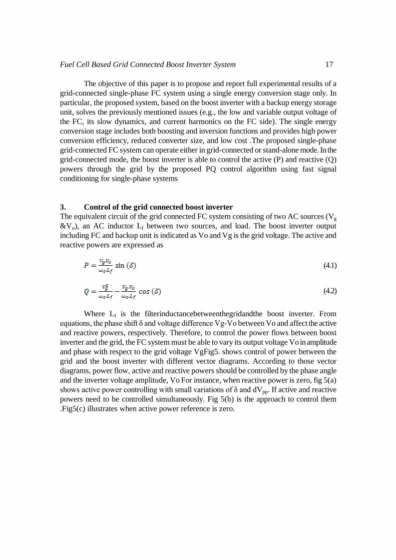
Fig 10.Simulation diagram of backup unit block
4.4 Boost inverter This subsection consists of the boost inverter, which consists of IGBT, inductors, capacitors and input to this block is SOFC fuel cell and backup unit also provided for giving low frequency ripple currents to boost inverter in order to avoid the slow dynamics of fuel Cell.
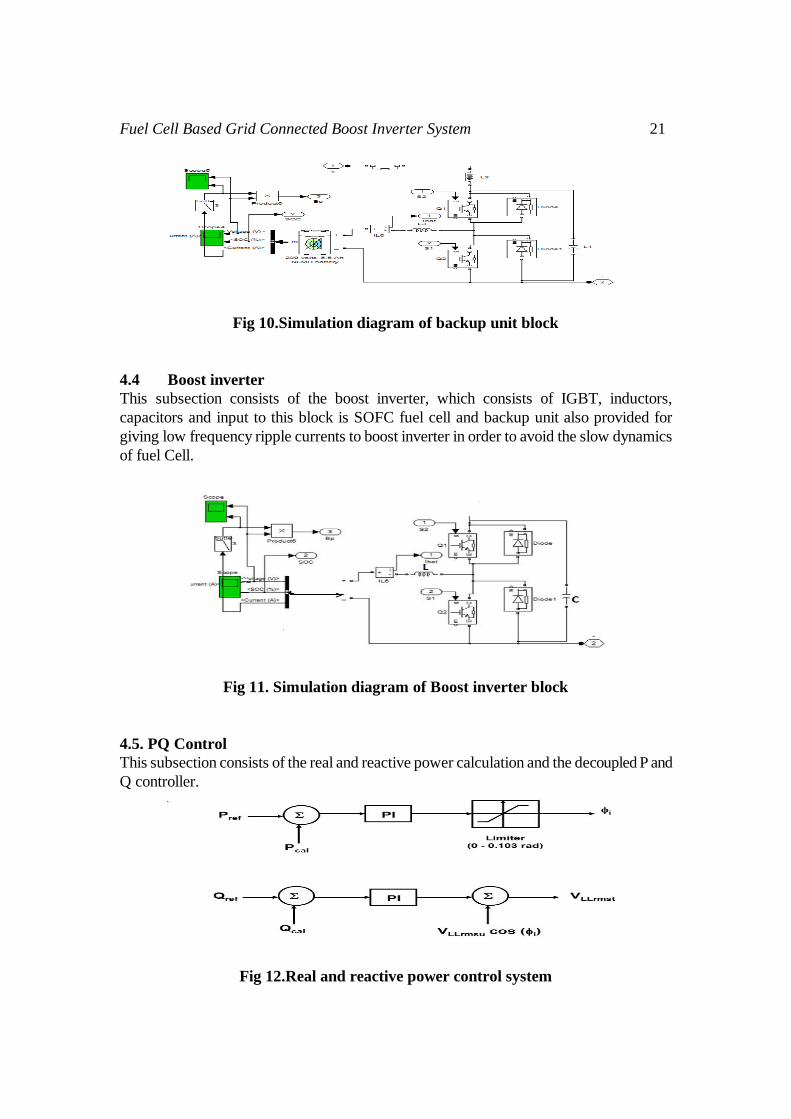
Fig 11. Simulation diagram of Boost inverter block 4.5. PQ Control This subsection consists of the real and reactive power calculation and the decoupled P and Q controller.
Fig 12.Real and reactive power control system

22 N.Venkateswarlu et al
Fig 13.Sub system for active and reactive power of fuel cell
Fig 14. Sub systems for active and reactive power of grid
TABLE 1.DESIGN PARAMETER
FC output voltage 36-69(72-cell FC) AC output voltage 220V RMS, single phase, 50Hz AC Grid voltage 220V,50Hz Switching frequency 20KHz Output power 1KW Vin 42V(min) Ro(resistance of L1 and L2) 10mΩ V1(t) 353V(max) V2(t) 42(min) ∆t1(maximum on time) 42.5µs(max at 20KHz) ∆iLmax 5% of iLmax ∆Vc 5% of V1max R1(load) 48.4Ω at 1KW Vb(battery voltage) 22V(min)-27.3(max) ILb1 45.5 A(max)
FC output voltage 39-69V(72 cell SOFC) AC output voltage 220V, 50Hz Switching frequency 20KHz Rated power 1.0KW(43V at 23.5 A) Power stack Semi stack-IGBT Controller DSP TMS320F28335 Voltage transducers LEM LV25-P

Fuel Cell Based Grid Connected Boost Inverter System 23
Current transducers LEM HAL50s Energy storage Two 12V-24Ah Ni-MH batteries L1&L2 700µH Lb1&Lb2 150µH Lf 5mH C1&C2&C3&C4 20µF PR1 KP:0.1,KI:10 PR2 KP:1,KI:1000 PI1 KP:0.1,KI:100 PI2 KP:1e-6,KI:1e-3 PI3 KP:5e-5,KI:0.2 PI4 KP:0.5,KI:0.03
Fig 15.Output voltages of the Boost inverter
Fig 16.Voltage and current of inverter
Fig 17.Inductor currents of the Boost inverter

24 N.Venkateswarlu et al
Fig 18. Active and Reactive Powers of the Grid
Fig 19. Output voltage of the fuel cell 5. CONCLUSION A dynamic model of the solid oxide fuel cell (SOFC) was developed in MATLAB.A boost inverter has been modeled and connected between the SOFC on the one side and the utility grid on the other side. A control strategy for the boost inverter switching signals has been discussed and modeled successfully. The inverter control scheme uses a decoupled PQ control strategy. The characteristics for the system have been obtained. The fuel cell, boost inverter, grid voltage waveforms have been plotted. In an industrial power generation, fuel cell is one of most important sources of distributed energy in the future. Modeling and simulation study of a SOFC power system is investigated in this project. A validated SOFC dynamic model is used to model the fuel cell system. A control strategy for the boost inverter switching signals has been discussed. 5.1 FUTURE SCOPE The fuel cell system developed in this thesis can be modified for improving the applicability of the system. In this thesis, the thermodynamic effect of the fuel cell has not been considered. Future work can involve inclusion of thermodynamic equations. The performance of the stack voltage with and without the temperature effect can be obtained and its overall effect on the load. In this thesis, single phase has been modeled for utility grid. The work can be further extended to a three phase system. Different placements of the fuel cell unit can be studied and analyzed. The performance of multiple units at multiple locations can also be studied. The performance of the fuel cell can also be tested by carrying out short circuit studies.

Fuel Cell Based Grid Connected Boost Inverter System 25
Reference [1] P. Thou thong, B. Davat, and S. Raël, “Drive friendly, Fuel cell High power
applications”, vol. 6, no. 1, pp. 69–76, 2008. [2] Jinhee Lee, Jinsang Jo, Sewan Choi and Soo-Bin Han, “A 10-kW SOFC Low-
Voltage Battery Hybrid Power Conditioning System for Residential Use”, IEEE transactions on energy conversion, vol. 21, no. 2, June 2006.
[3] Ram´on O. C´aceres and Ivo Barbi, “A Boost DC–AC Converter: Analysis, Design, and Experimentation”, IEEE transactions on power electronics, vol. 14, no. 1, January 1999.
[4] Ching-Tsai Pan and Ching-Ming Lai, “A High-Efficiency High Step-Up Converter with Low Switch Voltage Stress for Fuel-Cell System Applications”, IEEE transactions on industrial electronics, vol. 57, no. 6, June 2010.
[5] Ke Jin, Xinbo Ruan, Mengxiong Yang and Min Xu, “Power Management for Fuel-Cell Power System Cold Start”, IEEE transactions on power electronics, vol. 24, no. 10, October 2009

26 N.Venkateswarlu et al