
FTX and FTP Series Installation and Service Manual · FTX and FTP Series Installation and Service...
48
Curtiss-Wright | FTX Series Rev. C PN71855 5/26/17 1 FTX and FTP Series Installation and Service Manual Information furnished by Curtiss-Wright, Exlar Corporation, is believed to be accurate and reliable. However, no responsibility is assumed by Curtiss-Wright for its use. Curtiss-Wright reserves the right to change the design and operation of the equipment described herein and any associated motion products that may appear in this document. Information in this document pertaining to equipment not furnished by Curtiss-Wright should be confirmed by that equipment manufacturer. Curtiss-Wright assumes no responsibility for changes to information by other manufacturers or errors in that information or the description of that information. Information in this document is subject to change without notice. This document does not contain any export controlled technical data.
Transcript of FTX and FTP Series Installation and Service Manual · FTX and FTP Series Installation and Service...
Curtiss-Wright | FTX Series Rev. C PN71855 5/26/17 1
FTX and FTP Series
Installation and Service Manual
Information furnished by Curtiss-Wright, Exlar Corporation, is believed to be accurate and reliable. However, no responsibility is assumed by Curtiss-Wright for its use. Curtiss-Wright reserves the right to change the design and operation of the equipment described herein and any associated motion products that may appear in this document. Information in this document pertaining to equipment not furnished by Curtiss-Wright should be confirmed by that equipment manufacturer. Curtiss-Wright assumes no responsibility for changes to information by other manufacturers or errors in that information or the description of that information. Information in this document is subject to change without notice.
This document does not contain any export controlled technical data.
Curtiss-Wright | FTX Series Rev. C PN71855 5/26/17 2
TABLE OF CONTENTS 1.0 Introduction
1.1 Warranty and Limitations of Liability ................................................ 3 1.2 Safety Considerations .................................................................... 4 1.3 FTX Series Linear Actuators Overview ......................................... 5 1.4 Basic Actuator Construction ............................................................ 5 1.5 Actuator Drive Train Configurations ................................................ 7
2.0 Installation
2.1 Mounting Configurations ................................................................. 9 2.2 Mounting Considerations ................................................................ 9 2.3 Motor Installation ........................................................................... 10 2.4 Lubrication .................................................................................... 15 2.5 Anti-Rotate System ...................................................................... 23
3.0 Maintenance & Service
3.1 Seals ............................................................................................. 24 3.2 Drive Train ................................................................................... 26 3.3 Belt Tensioning ............................................................................ 27 3.4 Roller Screw .................................................................................. 32 3.5 End of Stroke Cushions ................................................................ 32 3.6 Inspection and Lubrication Procedure ........................................... 33
4.0 Optional Equipment
4.1 Mounting Options ......................................................................... 38 4.2 Standard Motor Mounting Configurations ..................................... 38 4.3 Limit Switches .............................................................................. 38 4.4 Rod Ends ..................................................................................... 40 4.5 Motors .......................................................................................... 40 4.6 Electronics ................................................................................... 40
5.0 Specifications
5.1 Life Calculations ........................................................................... 40 5.2 Load, Torque, and Linear Speed Calculations ............................. 40 5.3 Load and Speed Ratings .............................................................. 41
6.0 Troubleshooting
6.1 Mechanical Problems ................................................................... 42 6.2 Electrical Problems ...................................................................... 42 6.3 Returning a Product for Repair ..................................................... 43
7.0 Torque Spec
7.1 FTX095 Torque Specifications ..................................................... 44 7.1 FTX125 Torque Specifications ..................................................... 45 7.2 FTX215 Torque Specifications ...................................................... 46 7.3 FTP215 Torque Specifications ...................................................... 47 7.4 Motor Fastener Torque Specifications ......................................... 48
Curtiss-Wright | FTX Series Rev. C PN71855 5/26/17 3
1.0 Introduction
1.1 Warranty and Limitation of Liability Products are warranted for two years from date of manufacture as determined by the serial number
on the product label. Labels are generated and applied to the product at the time of shipment. The first and second digits are the year and the third and fourth digits represent the manufacturing week. Product repairs are warranted for 90 days from the date of the repair. The date of repair is recorded within Exlar’s database tracked by individual product serial number.
Exlar Corporation warrants its product(s) to the original purchaser and in the case of original equipment manufacturers, to their original customer to be free from defects in material and workmanship and to be made only in accordance with Exlar’s standard published catalog specifications for the product(s) as published at the time of purchase. Warranty or performance to any other specifications is not covered by this warranty unless otherwise agreed to in writing by Exlar and documented as part of any and all contracts, including but not limited to purchase orders, sales orders, order confirmations, purchase contracts and purchase agreements. In no event shall Exlar be liable or have any responsibility under such warranty if the product(s) has been improperly stored, installed, used or maintained, or if Buyer has permitted any unauthorized modifications, adjustments and/or repairs to such product(s). Seller's obligation hereunder is limited solely to repairing or replacing (at its opinion), at the factory any product(s), or parts thereof, which prove to Seller's satisfaction to be defective as a result of defective materials, or workmanship and within the period of time, in accordance with the Seller's stated product warranty (see Terms and Conditions above), provided, however, that written notice of claimed defects shall have been given to Exlar within thirty (30) days from the date of any such defect is first discovered. The product(s) claimed to be defective must be returned to Exlar, transportation prepaid by Buyer, with written specification of the claimed defect. Evidence acceptable to Exlar must be furnished that the claimed defects were not caused by misuse, abuse, or neglect by anyone other than Exlar.
Components such as seals, wipers, bearings, brakes, bushings, gears, splines, and roller screw parts are considered wear parts and must be inspected and serviced on a regular basis. Any damage caused by failure to properly lubricate Exlar products and/or to replace wear parts at appropriate times, is not covered by this warranty. Any damage due to excessive loading is not covered by this warranty.
The use of products or components under load such that they reach the end of their expected life is a normal characteristic of the application of mechanical products. Reaching the end of a product’s expected life does not indicate any defect in material or workmanship and is not covered by this warranty.
Costs for shipment of units returned to the factory for warranty repairs are the responsibility of the owner of the product. Exlar will return ship all warranty repairs or replacements via UPS Ground at no cost to the customer.
For international customers, Exlar will return ship warranty repairs or replacements via UPS Expedited Service and cover the associated shipping costs. Any VAT or local country taxes are the responsibility of the owner of the product.
The foregoing warranty is in lieu of all other warranties (except as Title), whether expressed or implied, including without limitation, any warranty of merchantability, or of fitness for any particular purpose, other than as expressly set forth and to the extent specified herein, and is in lieu of all other obligations or liabilities on the part of Exlar.
Seller's maximum liability with respect to these terms and conditions and any resulting sale, arising from any cause whatsoever, including without limitation, breach of contract or negligence, shall not exceed the price specified herein of the product(s) giving rise to the claim, and in no event shall Exlar be liable under this warranty otherwise for special, incidental or consequential damages, whether similar or dissimilar, of any nature arising or resulting from the purchase, installation, removal, repair,
operation, use or breakdown of the product(s) or any other cause whatsoever, including negligence. The foregoing warranty shall also apply to products or parts which have been repaired or replaced
pursuant to such warranty, and within the period of time, in accordance with Seller's stated warranty. NO PERSON INCLUDING ANY AGENT OR REPRESENTATIVE OF EXLAR IS AUTHORIZED
TO MAKE ANY REPRESENTATION OR WARRANTY ON BEHALF OF EXLAR CONCERNING ANY PRODUCTS MANUFACTURED BY EXLAR, EXCEPT TO REFER PURCHASERS TO THIS WARRANTY.
Curtiss-Wright | FTX Series Rev. C PN71855 5/26/17 4
1.2 Safety Considerations As with any electro-mechanical device, safety should be considered
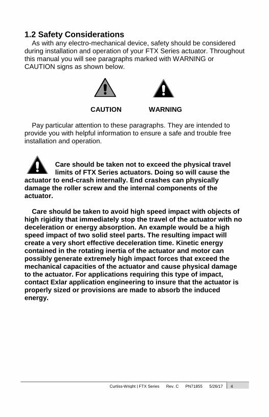
during installation and operation of your FTX Series actuator. Throughout this manual you will see paragraphs marked with WARNING or CAUTION signs as shown below.
CAUTION WARNING
Pay particular attention to these paragraphs. They are intended to provide you with helpful information to ensure a safe and trouble free installation and operation.
Care should be taken not to exceed the physical travel limits of FTX Series actuators. Doing so will cause the
actuator to end-crash internally. End crashes can physically damage the roller screw and the internal components of the actuator.
Care should be taken to avoid high speed impact with objects of
high rigidity that immediately stop the travel of the actuator with no deceleration or energy absorption. An example would be a high speed impact of two solid steel parts. The resulting impact will create a very short effective deceleration time. Kinetic energy contained in the rotating inertia of the actuator and motor can possibly generate extremely high impact forces that exceed the mechanical capacities of the actuator and cause physical damage to the actuator. For applications requiring this type of impact, contact Exlar application engineering to insure that the actuator is properly sized or provisions are made to absorb the induced energy.
Curtiss-Wright | FTX Series Rev. C PN71855 5/26/17 5
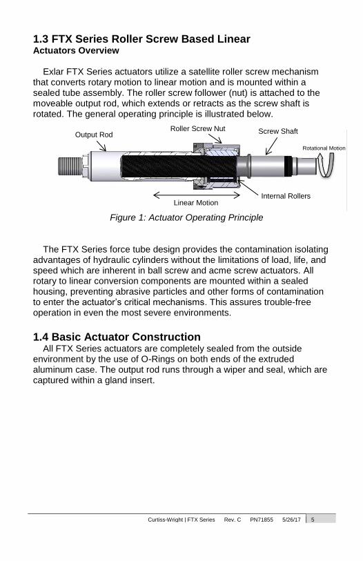
1.3 FTX Series Roller Screw Based Linear
Actuators Overview Exlar FTX Series actuators utilize a satellite roller screw mechanism
that converts rotary motion to linear motion and is mounted within a sealed tube assembly. The roller screw follower (nut) is attached to the moveable output rod, which extends or retracts as the screw shaft is rotated. The general operating principle is illustrated below.
Figure 1: Actuator Operating Principle
The FTX Series force tube design provides the contamination isolating
advantages of hydraulic cylinders without the limitations of load, life, and speed which are inherent in ball screw and acme screw actuators. All rotary to linear conversion components are mounted within a sealed housing, preventing abrasive particles and other forms of contamination to enter the actuator’s critical mechanisms. This assures trouble-free operation in even the most severe environments.
1.4 Basic Actuator Construction
All FTX Series actuators are completely sealed from the outside environment by the use of O-Rings on both ends of the extruded aluminum case. The output rod runs through a wiper and seal, which are captured within a gland insert.
Output Rod
Linear Motion
Screw Shaft
Internal Rollers
Roller Screw Nut
Rotational Motion

Curtiss-Wright | FTX Series Rev. C PN71855 5/26/17 6
The extruded aluminum case is epoxy coated (powder coated) on all external surfaces. In cases where a motor is mounted in a parallel configuration (see section 1.5) the pulley cover is also epoxy coated. All other aluminum parts (faceplate, end plate, inline adapters etc.) are anodized. All steel mounting parts (flange plates, trunnion components, etc.) are finished with QPQ.
In applications where corrosive chemicals are to come in contact with the actuator, it may be necessary to employ
non-standard coatings or materials. Contact Exlar for more details. Unless otherwise specified, the output rod on a standard FTX Series
actuator is manufactured from case hardened and chrome plated carbon steel. The case hardened chrome plated rod provides a very tough and wear resistant surface for the rod seal to operate against.
If the surface of the output rod gets dinged or severally scratched, the wiper and or rod seal may be compromised, causing contamination of the internal components in the
actuator.
The base metal used in the standard output rod does not resist corrosive environments. Custom materials or plating may need to be used if the output rod is to come in contact
with a corrosively aggressive environment. Contact Exlar for more details.
The standard tie rods on all FTX Series actuators are manufactured out of 17-4 PH stainless steel and are corrosion resistant to most non-chlorine based chemicals.
Curtiss-Wright | FTX Series Rev. C PN71855 5/26/17 7
Figure 2: FTX Actuator with Parallel Motor Mount
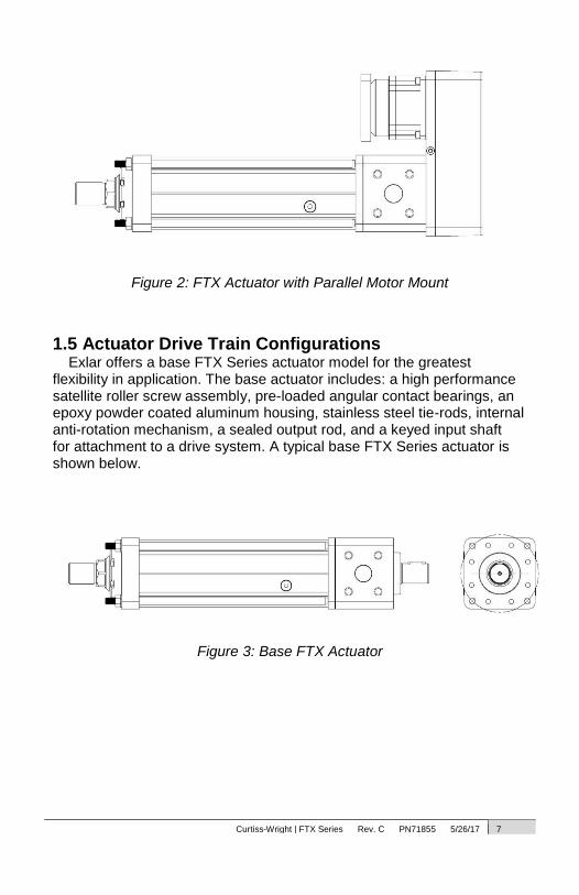
1.5 Actuator Drive Train Configurations Exlar offers a base FTX Series actuator model for the greatest
flexibility in application. The base actuator includes: a high performance satellite roller screw assembly, pre-loaded angular contact bearings, an epoxy powder coated aluminum housing, stainless steel tie-rods, internal anti-rotation mechanism, a sealed output rod, and a keyed input shaft for attachment to a drive system. A typical base FTX Series actuator is shown below.
Figure 3: Base FTX Actuator
Curtiss-Wright | FTX Series Rev. C PN71855 5/26/17 8
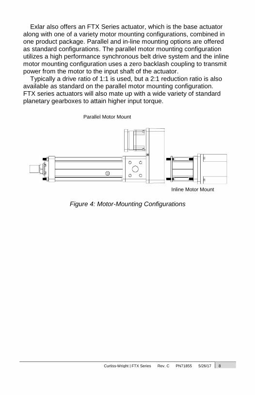
Exlar also offers an FTX Series actuator, which is the base actuator along with one of a variety motor mounting configurations, combined in one product package. Parallel and in-line mounting options are offered as standard configurations. The parallel motor mounting configuration utilizes a high performance synchronous belt drive system and the inline motor mounting configuration uses a zero backlash coupling to transmit power from the motor to the input shaft of the actuator.
Typically a drive ratio of 1:1 is used, but a 2:1 reduction ratio is also available as standard on the parallel motor mounting configuration. FTX series actuators will also mate up with a wide variety of standard planetary gearboxes to attain higher input torque.
Figure 4: Motor-Mounting Configurations
Parallel Motor Mount
Inline Motor Mount
Curtiss-Wright | FTX Series Rev. C PN71855 5/26/17 9
2.0 Installation
2.1 Mounting Configurations The actuators come with a variety of mounting configurations as well.
Refer to the Exlar catalog to review what options are available on the desired frame size.
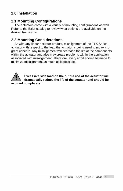
2.2 Mounting Considerations As with any linear actuator product, misalignment of the FTX Series
actuator with respect to the load the actuator is being used to move is of great concern. Any misalignment will decrease the life of the components within the actuator and also may create problems within the application associated with misalignment. Therefore, every effort should be made to minimize misalignment as much as is possible.
Excessive side load on the output rod of the actuator will dramatically reduce the life of the actuator and should be
avoided completely.
Curtiss-Wright | FTX Series Rev. C PN71855 5/26/17 10
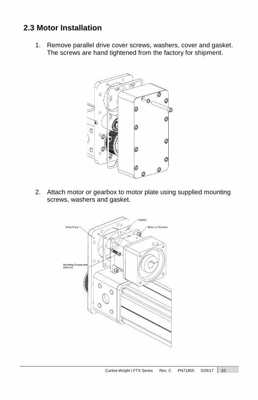
2.3 Motor Installation
1. Remove parallel drive cover screws, washers, cover and gasket. The screws are hand tightened from the factory for shipment.
2. Attach motor or gearbox to motor plate using supplied mounting screws, washers and gasket.

Curtiss-Wright | FTX Series Rev. C PN71855 5/26/17 11
3. Attach bushing and pulley to motor or gearbox output shaft and actuator input shaft. Refer to belt tensioning procedure for the approximate distance between the pulley and motor plate. Torque the Taper-Lock screws to specification. The Taper-Lock bushings can be used with or without a key.
Figure 5: Motor and Pulley with Taper-Lock Bushing

Curtiss-Wright | FTX Series Rev. C PN71855 5/26/17 12
4. If the parallel drive assembly is supplied with a keyless style bushing, a key cannot be used. The bushing may have to be reversed to attain proper pulley distance. In some instances the bushing and pulley may have to be installed before the motor is attached to the motor plate to allow clearance for tightening the bushing. Torque the bushing using the large hex and refer to the torque specification for bushing torque.
Figure 6: Motor Pulley with keyless Style Bushing
Curtiss-Wright | FTX Series Rev. C PN71855 5/26/17 13
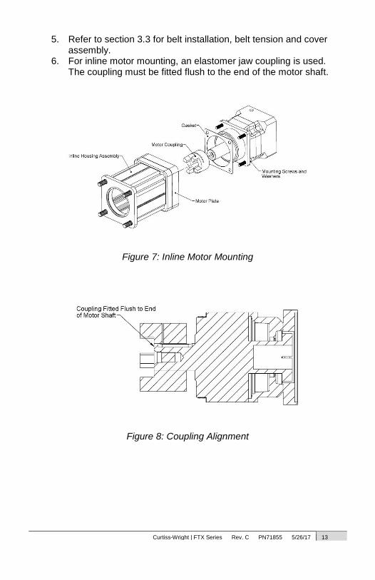
5. Refer to section 3.3 for belt installation, belt tension and cover assembly.
6. For inline motor mounting, an elastomer jaw coupling is used. The coupling must be fitted flush to the end of the motor shaft.
Figure 7: Inline Motor Mounting
Figure 8: Coupling Alignment
Curtiss-Wright | FTX Series Rev. C PN71855 5/26/17 14
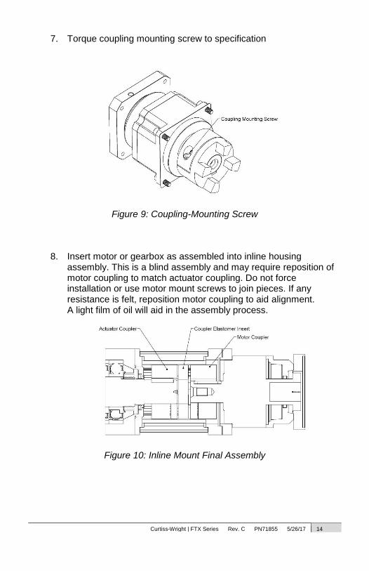
7. Torque coupling mounting screw to specification
Figure 9: Coupling-Mounting Screw
8. Insert motor or gearbox as assembled into inline housing
assembly. This is a blind assembly and may require reposition of motor coupling to match actuator coupling. Do not force installation or use motor mount screws to join pieces. If any resistance is felt, reposition motor coupling to aid alignment. A light film of oil will aid in the assembly process.
Figure 10: Inline Mount Final Assembly

Curtiss-Wright | FTX Series Rev. C PN71855 5/26/17 15
2.4 Lubrication Grease Specification
FTX Series actuators are shipped from the factory fully lubricated with high temperature grease. Exlar uses Mobilith SHC 220, a high performance, extreme-pressure grease. The unique physical properties of the synthetic base oil provide outstanding protection against wear, rust, corrosion and high or low-temperature degradation. Mobilith SHC allows for very low starting and running torque values. Its operating range is -40 degrees C to 177 degrees C (-40 degrees F to 350 degrees F).
Periodic inspection and renewal of the bearing and roller screw grease
is recommended. Re-greasing and maintenance schedules are largely based upon customer applications. Contact the factory for general recommendations on re-greasing schedules.
Follow the procedure in section 3.6 for renewing the lubrication.
Upon initial startup of your FTX Series actuator, cold grease may cause increased motor torque to operate
actuator. Once grease has warmed up required motor torque should decrease. Elevated operating temperatures may result in shorter lubrication renewal periods.
Grease Zerk Access Plug

Curtiss-Wright | FTX Series Rev. C PN71855 5/26/17 16
Oil Specification The FTX and FTP Series use Mobil SHC 626 for oil fill. The actuator is
shipped empty and only receives a light oil coating from the factory for initial test. The actuator must be filled by the customer for their specific application. The case features integrated sight glasses and sight tubing to ensure a proper oil fill level depending upon the orientation of the actuator. Slight foaming of the oil in operation is normal and is a result of the initial coating of grease from the bearings.
Figure 11a: Horizontal Oil Fill Sight Glasses
Figure 11b: Vertical Oil Fill Sight Tube and Fill Ports
For lubrication of seals see section 3.1. For inspection and lubrication procedure see section 3.6.
Curtiss-Wright | FTX Series Rev. C PN71855 5/26/17 17
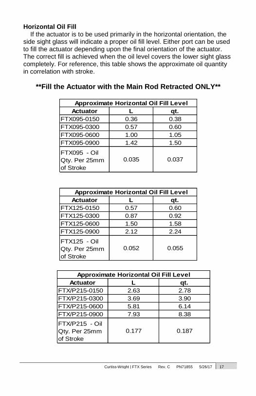
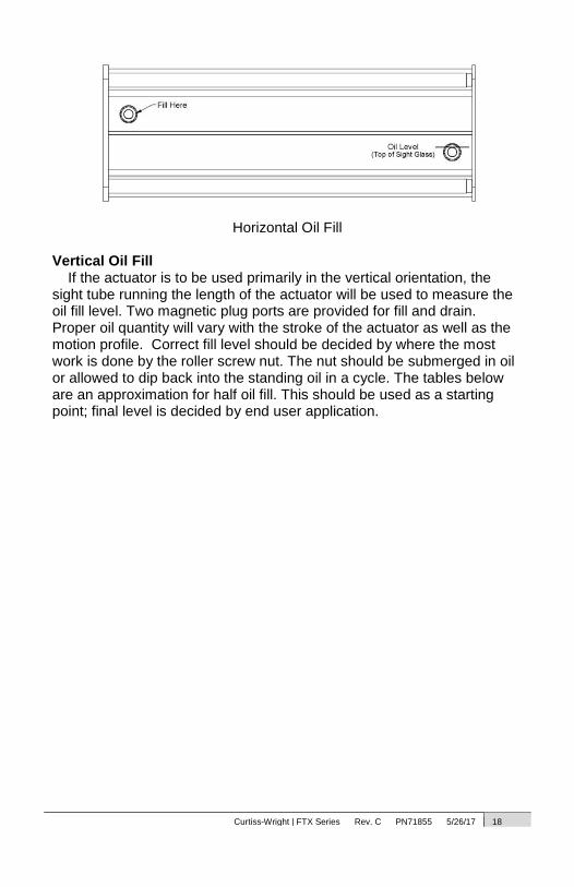
Horizontal Oil Fill If the actuator is to be used primarily in the horizontal orientation, the
side sight glass will indicate a proper oil fill level. Either port can be used to fill the actuator depending upon the final orientation of the actuator. The correct fill is achieved when the oil level covers the lower sight glass completely. For reference, this table shows the approximate oil quantity in correlation with stroke.
**Fill the Actuator with the Main Rod Retracted ONLY**
Approximate Horizontal Oil Fill Level
Actuator L qt.
FTX095-0150 0.36 0.38
FTX095-0300 0.57 0.60
FTX095-0600 1.00 1.05
FTX095-0900 1.42 1.50
FTX095 - Oil
Qty. Per 25mm
of Stroke
0.035 0.037
Approximate Horizontal Oil Fill Level
Actuator L qt.
FTX125-0150 0.57 0.60
FTX125-0300 0.87 0.92
FTX125-0600 1.50 1.58
FTX125-0900 2.12 2.24
FTX125 - Oil
Qty. Per 25mm
of Stroke
0.052 0.055
Approximate Horizontal Oil Fill Level
Actuator L qt.
FTX/P215-0150 2.63 2.78
FTX/P215-0300 3.69 3.90
FTX/P215-0600 5.81 6.14
FTX/P215-0900 7.93 8.38
FTX/P215 - Oil
Qty. Per 25mm
of Stroke
0.177 0.187
Curtiss-Wright | FTX Series Rev. C PN71855 5/26/17 18
Horizontal Oil Fill
Vertical Oil Fill
If the actuator is to be used primarily in the vertical orientation, the sight tube running the length of the actuator will be used to measure the oil fill level. Two magnetic plug ports are provided for fill and drain. Proper oil quantity will vary with the stroke of the actuator as well as the motion profile. Correct fill level should be decided by where the most work is done by the roller screw nut. The nut should be submerged in oil or allowed to dip back into the standing oil in a cycle. The tables below are an approximation for half oil fill. This should be used as a starting point; final level is decided by end user application.
Curtiss-Wright | FTX Series Rev. C PN71855 5/26/17 19
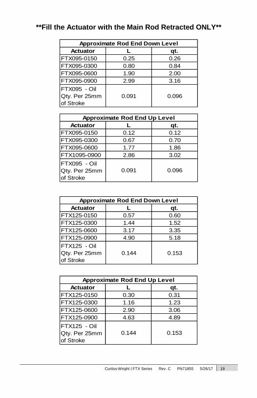
**Fill the Actuator with the Main Rod Retracted ONLY**
Approximate Rod End Down Level
Actuator L qt.
FTX095-0150 0.25 0.26
FTX095-0300 0.80 0.84
FTX095-0600 1.90 2.00
FTX095-0900 2.99 3.16
FTX095 - Oil
Qty. Per 25mm
of Stroke
0.091 0.096
Approximate Rod End Down Level
Actuator L qt.
FTX125-0150 0.57 0.60
FTX125-0300 1.44 1.52
FTX125-0600 3.17 3.35
FTX125-0900 4.90 5.18
FTX125 - Oil
Qty. Per 25mm
of Stroke
0.144 0.153
Approximate Rod End Up Level
Actuator L qt.
FTX095-0150 0.12 0.12
FTX095-0300 0.67 0.70
FTX095-0600 1.77 1.86
FTX1095-0900 2.86 3.02
FTX095 - Oil
Qty. Per 25mm
of Stroke
0.091 0.096
Approximate Rod End Up Level
Actuator L qt.
FTX125-0150 0.30 0.31
FTX125-0300 1.16 1.23
FTX125-0600 2.90 3.06
FTX125-0900 4.63 4.89
FTX125 - Oil
Qty. Per 25mm
of Stroke
0.144 0.153

Curtiss-Wright | FTX Series Rev. C PN71855 5/26/17 20
Approximate Rod End Down Level
Actuator L qt.
FTX/P215-0150 2.11 2.23
FTX/P215-0300 4.68 4.95
FTX/P215-0600 9.83 10.39
FTX/P215-0900 14.98 15.83
FTX/P215 - Oil
Qty. Per 25mm of
Stroke
0.429 0.453
Vertical Oil Fill Ports and Sight Tube
Approximate Rod End Up Level
Actuator L qt.
FTX/P215-0150 1.75 1.84
FTX/P215-0300 4.32 4.56
FTX/P215-0600 9.47 10.00
FTX/P215-0900 14.62 15.44
FTX/P215 - Oil
Qty. Per 25mm
of Stroke
0.429 0.453
Curtiss-Wright | FTX Series Rev. C PN71855 5/26/17 21
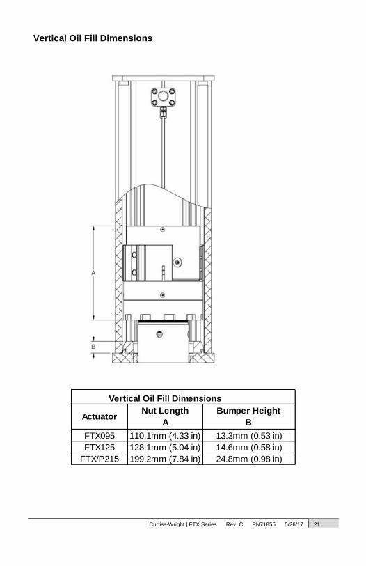
Vertical Oil Fill Dimensions
Vertical Oil Fill Dimensions
ActuatorNut Length
A
Bumper Height
B
FTX095 110.1mm (4.33 in) 13.3mm (0.53 in)
FTX125 128.1mm (5.04 in) 14.6mm (0.58 in)
FTX/P215 199.2mm (7.84 in) 24.8mm (0.98 in)
Curtiss-Wright | FTX Series Rev. C PN71855 5/26/17 22
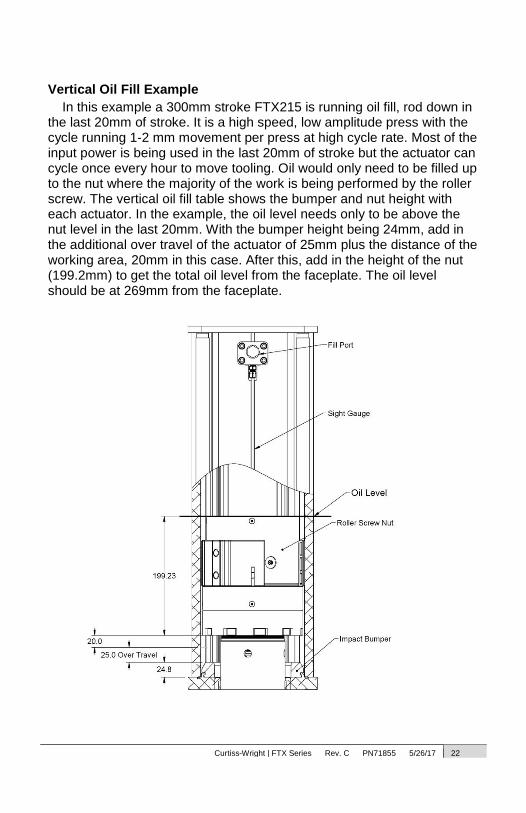
Vertical Oil Fill Example
In this example a 300mm stroke FTX215 is running oil fill, rod down in the last 20mm of stroke. It is a high speed, low amplitude press with the cycle running 1-2 mm movement per press at high cycle rate. Most of the input power is being used in the last 20mm of stroke but the actuator can cycle once every hour to move tooling. Oil would only need to be filled up to the nut where the majority of the work is being performed by the roller screw. The vertical oil fill table shows the bumper and nut height with each actuator. In the example, the oil level needs only to be above the nut level in the last 20mm. With the bumper height being 24mm, add in the additional over travel of the actuator of 25mm plus the distance of the working area, 20mm in this case. After this, add in the height of the nut (199.2mm) to get the total oil level from the faceplate. The oil level should be at 269mm from the faceplate.

Curtiss-Wright | FTX Series Rev. C PN71855 5/26/17 23
2.5 Anti-Rotate Mechanism FTX Series actuators have an internal anti-rotate mechanism guided
by extruded channels in the actuator case. The anti-rotates are comprised of a high performance, thermal and abrasion-resistant polymer. This precise mechanism will limit angular backlash and is designed to withstand the high force and speed created by these actuators. However, there is a limit to the amount of torque they can withstand, and every effort should be made to resist installation torque applied when tightening a nut or coupling on the output rod. There are wrench flats provided on every standard output rod to aid in resisting installation torque.
Figure 12: Anti-Rotate Mechanism
During installation, do not apply more than the following values for torque to the output rod without opposing that
torque. Doing so can damage the anti-rotate mechanism inside the actuator.
FTX095----25 lbf-ft (34 Nm) FTX125----50 lbf-ft (67 Nm) FTX/P215----100 lbf-ft (135 Nm)
Curtiss-Wright | FTX Series Rev. C PN71855 5/26/17 24
3.0 Maintenance & Service
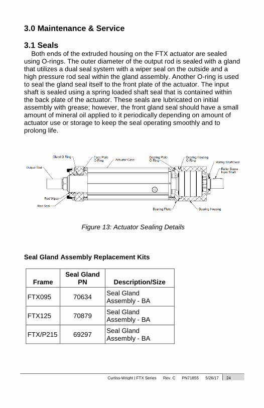
3.1 Seals Both ends of the extruded housing on the FTX actuator are sealed
using O-rings. The outer diameter of the output rod is sealed with a gland that utilizes a dual seal system with a wiper seal on the outside and a high pressure rod seal within the gland assembly. Another O-ring is used to seal the gland seal itself to the front plate of the actuator. The input shaft is sealed using a spring loaded shaft seal that is contained within the back plate of the actuator. These seals are lubricated on initial assembly with grease; however, the front gland seal should have a small amount of mineral oil applied to it periodically depending on amount of actuator use or storage to keep the seal operating smoothly and to prolong life.
Figure 13: Actuator Sealing Details
Seal Gland Assembly Replacement Kits
Frame Seal Gland
PN Description/Size
FTX095 70634 Seal Gland Assembly - BA
FTX125 70879 Seal Gland Assembly - BA
FTX/P215 69297 Seal Gland Assembly - BA
Curtiss-Wright | FTX Series Rev. C PN71855 5/26/17 25
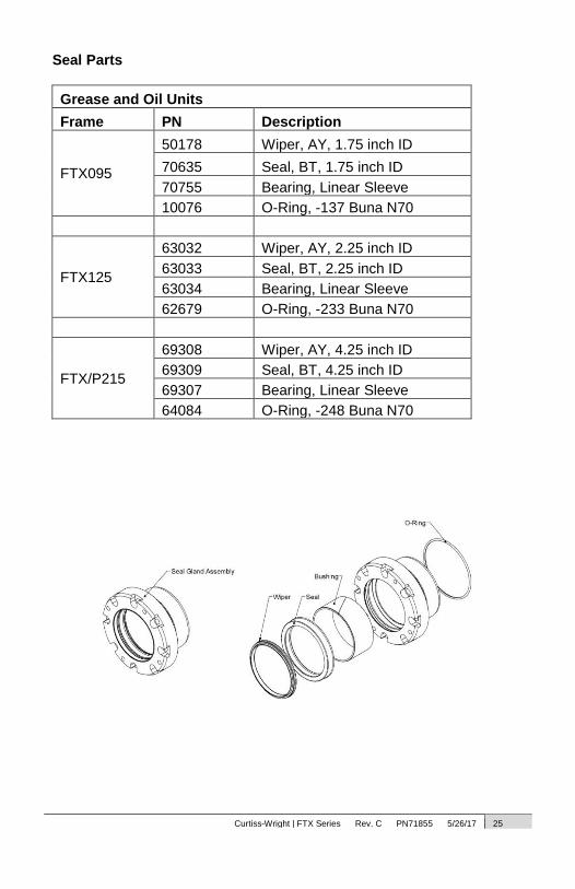
Seal Parts
Grease and Oil Units
Frame PN Description
FTX095
50178 Wiper, AY, 1.75 inch ID
70635 Seal, BT, 1.75 inch ID
70755 Bearing, Linear Sleeve
10076 O-Ring, -137 Buna N70
FTX125
63032 Wiper, AY, 2.25 inch ID
63033 Seal, BT, 2.25 inch ID
63034 Bearing, Linear Sleeve
62679 O-Ring, -233 Buna N70
FTX/P215
69308 Wiper, AY, 4.25 inch ID
69309 Seal, BT, 4.25 inch ID
69307 Bearing, Linear Sleeve
64084 O-Ring, -248 Buna N70
Curtiss-Wright | FTX Series Rev. C PN71855 5/26/17 26
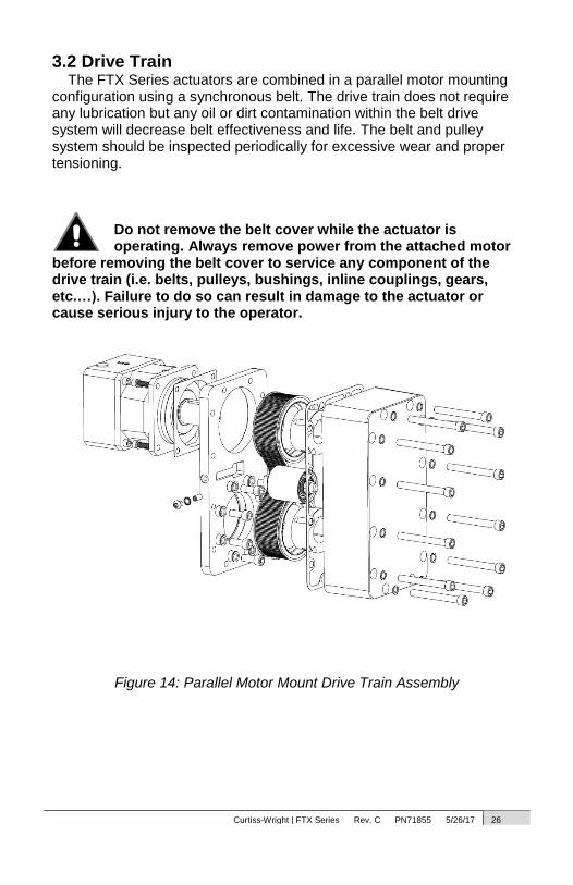
3.2 Drive Train The FTX Series actuators are combined in a parallel motor mounting
configuration using a synchronous belt. The drive train does not require any lubrication but any oil or dirt contamination within the belt drive system will decrease belt effectiveness and life. The belt and pulley system should be inspected periodically for excessive wear and proper tensioning.
Do not remove the belt cover while the actuator is operating. Always remove power from the attached motor
before removing the belt cover to service any component of the drive train (i.e. belts, pulleys, bushings, inline couplings, gears, etc.…). Failure to do so can result in damage to the actuator or cause serious injury to the operator.
Figure 14: Parallel Motor Mount Drive Train Assembly
Curtiss-Wright | FTX Series Rev. C PN71855 5/26/17 27
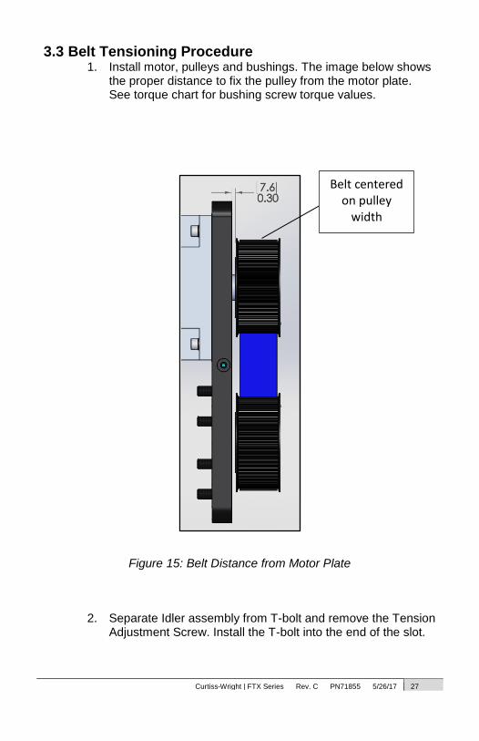
3.3 Belt Tensioning Procedure 1. Install motor, pulleys and bushings. The image below shows
the proper distance to fix the pulley from the motor plate. See torque chart for bushing screw torque values.
Figure 15: Belt Distance from Motor Plate
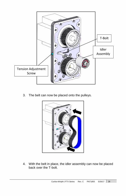
2. Separate Idler assembly from T-bolt and remove the Tension
Adjustment Screw. Install the T-bolt into the end of the slot.
Belt centered on pulley
width
Curtiss-Wright | FTX Series Rev. C PN71855 5/26/17 28
3. The belt can now be placed onto the pulleys.
4. With the belt in place, the idler assembly can now be placed
back over the T-bolt.
T-Bolt
Tension Adjustment Screw
Idler Assembly
Curtiss-Wright | FTX Series Rev. C PN71855 5/26/17 29
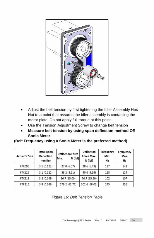
Adjust the belt tension by first tightening the Idler Assembly Hex
Nut to a point that assures the idler assembly is contacting the
motor plate. Do not apply full torque at this point.
Use the Tension Adjustment Screw to change belt tension
Measure belt tension by using span deflection method OR
Sonic Meter
(Belt Frequency using a Sonic Meter is the preferred method)
Actuator Size
Installation
Deflection
mm (in)
Deflection Force
Min. N (lbf)
Deflection
Force Max.
N (lbf)
Frequency
Min.
Hz
Frequency
Max.
Hz
FTX095 3.1 (0.122) 27.0 (6.07) 28.6 (6.43) 137 143
FTX125 3.1 (0.122) 38.2 (8.61) 40.6 (9.14) 118 124
FTX215 3.8 (0.149) 66.7 (15.00) 70.7 (15.90) 102 107
FTP215 3.8 (0.149) 279.2 (62.77) 302.6 (68.03) 245 256
Figure 16: Belt Tension Table
Curtiss-Wright | FTX Series Rev. C PN71855 5/26/17 30
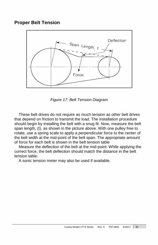
Proper Belt Tension
Figure 17: Belt Tension Diagram
These belt drives do not require as much tension as other belt drives that depend on friction to transmit the load. The installation procedure should begin by installing the belt with a snug fit. Now, measure the belt span length, (t), as shown in the picture above. With one pulley free to rotate, use a spring scale to apply a perpendicular force to the center of the belt width at the mid-point of the belt span. The appropriate amount of force for each belt is shown in the belt tension table
Measure the deflection of the belt at the mid-point. While applying the correct force, the belt deflection should match the distance in the belt tension table.
A sonic tension meter may also be used if available.
Curtiss-Wright | FTX Series Rev. C PN71855 5/26/17 31
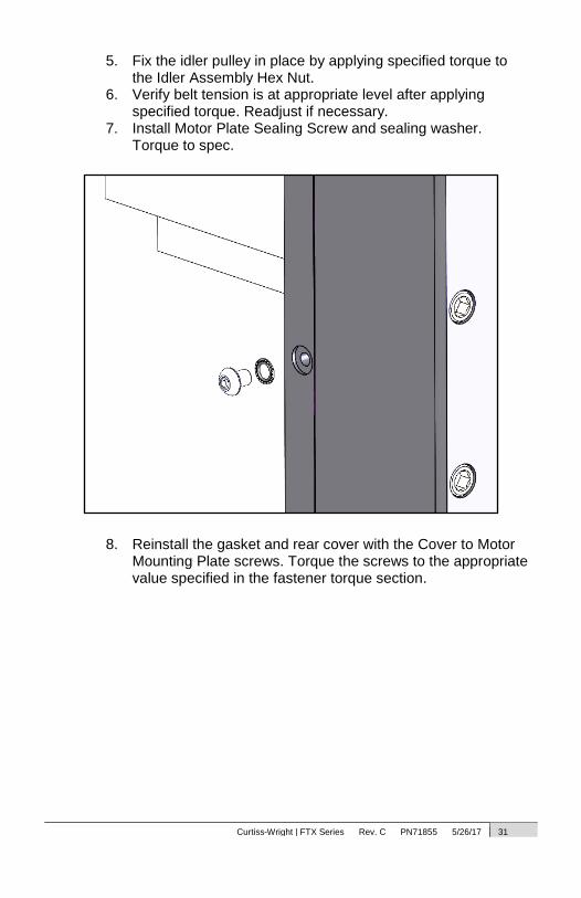
5. Fix the idler pulley in place by applying specified torque to the Idler Assembly Hex Nut.
6. Verify belt tension is at appropriate level after applying specified torque. Readjust if necessary.
7. Install Motor Plate Sealing Screw and sealing washer. Torque to spec.
8. Reinstall the gasket and rear cover with the Cover to Motor Mounting Plate screws. Torque the screws to the appropriate value specified in the fastener torque section.

Curtiss-Wright | FTX Series Rev. C PN71855 5/26/17 32
3.4 Roller Screw The satellite roller screw used within the FTX Series actuators is a
precision-machined mechanism, which is fully greased upon assembly. Lubrication of the roller screw should be maintained in accordance with section 2.3. The biggest enemies to this mechanism are shock loading and radial loads (side loads). Loading the roller screw in such a manner will cause premature failure.
Do not run the roller screw into the end of its stroke (in either extension or retraction), as this will severely damage
the actuator and/or application.
3.5 End of Stroke Cushions Every FTX Series actuator is equipped with impact bumpers, which
are designed to protect the actuator from accidental over extension or retraction.
This is a fail-safe only and should not be used as a limit to stroke.
Figure 18: Actuator End of Stroke Cushions
FTX Series actuators are designed with an additional 25 mm of travel
over nominal stroke. This allows users to utilize the full nominal stroke without causing damage by end crashing.
Curtiss-Wright | FTX Series Rev. C PN71855 5/26/17 33
Care should be taken not to exceed the physical travel limits of FTX Series actuators. Doing so will cause the
actuator to end-crash internally. End crashes can physically damage the roller screw and the internal components of the actuator.
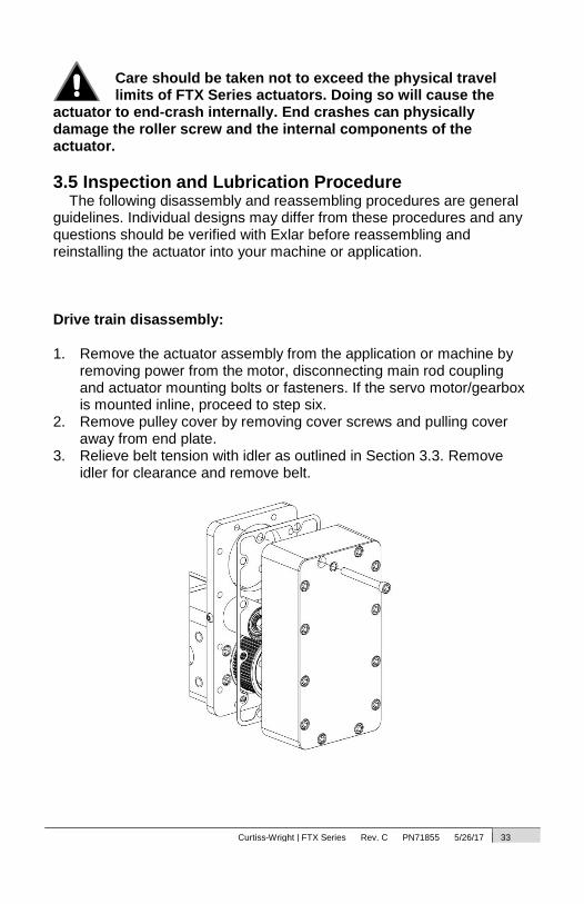
3.5 Inspection and Lubrication Procedure The following disassembly and reassembling procedures are general
guidelines. Individual designs may differ from these procedures and any questions should be verified with Exlar before reassembling and reinstalling the actuator into your machine or application.
Drive train disassembly: 1. Remove the actuator assembly from the application or machine by
removing power from the motor, disconnecting main rod coupling and actuator mounting bolts or fasteners. If the servo motor/gearbox is mounted inline, proceed to step six.
2. Remove pulley cover by removing cover screws and pulling cover away from end plate.
3. Relieve belt tension with idler as outlined in Section 3.3. Remove idler for clearance and remove belt.
Curtiss-Wright | FTX Series Rev. C PN71855 5/26/17 34
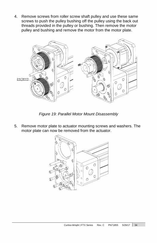
4. Remove screws from roller screw shaft pulley and use these same screws to push the pulley bushing off the pulley using the back out threads provided in the pulley or bushing. Then remove the motor pulley and bushing and remove the motor from the motor plate.
Figure 19: Parallel Motor Mount Disassembly
5. Remove motor plate to actuator mounting screws and washers. The
motor plate can now be removed from the actuator.
Curtiss-Wright | FTX Series Rev. C PN71855 5/26/17 35
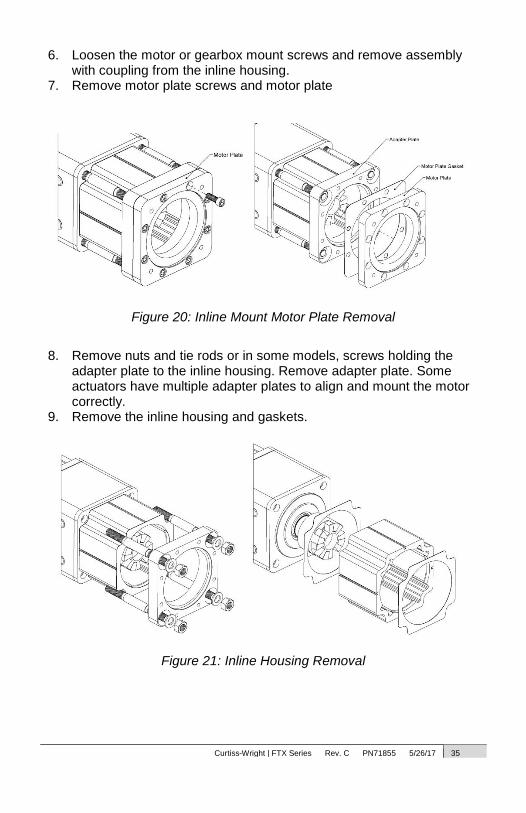
6. Loosen the motor or gearbox mount screws and remove assembly with coupling from the inline housing.
7. Remove motor plate screws and motor plate
Figure 20: Inline Mount Motor Plate Removal
8. Remove nuts and tie rods or in some models, screws holding the adapter plate to the inline housing. Remove adapter plate. Some actuators have multiple adapter plates to align and mount the motor correctly.
9. Remove the inline housing and gaskets.
Figure 21: Inline Housing Removal

Curtiss-Wright | FTX Series Rev. C PN71855 5/26/17 36
10. Loosen the actuator coupling mounting screw and remove coupling. (Note: For installation, the actuator coupling is mounted flush with the end of the input shaft.) Remove the inline housing adapter plate.
11. Installation is the reverse of removal.

Curtiss-Wright | FTX Series Rev. C PN71855 5/26/17 37
Grease Maintenance Procedure: The actuator will need periodic re-greasing based upon final use. The
maintenance schedule will depend upon load, speed and duty cycle. High speed or load along with high duty cycle will need maintenance more often. The screw should be cycled its entire stroke periodically to redistribute grease, especially in short stroke applications.
To re-grease the roller screw, remove the grease access plug and move the actuator out from the rear stop 25mm. The grease zerk will now be accessible. Follow the chart below for the correct amount of grease to use. Cycle the unit after several cc’s of grease to distribute.
Figure 22: Grease Port Location Apply grease into zerk through port in case,
cycle actuator to distribute grease.
Actuator
Size
Initial Grease Fill
(cc)
Additional cc Grease
per 25mm Stroke
FTX095 5.25 0.26
FTX125 7.88 1.00
FTX215 22.00 2.00
Routine maintenance only requires additional grease for the roller screw. See table above for amount of grease per 25mm of stroke. For example, if the actuator is 300 mm stroke and the additional cc per 25mm stroke is 3 cc, total amount of grease is 36 cc when routine maintenance is performed.
Curtiss-Wright | FTX Series Rev. C PN71855 5/26/17 38
4.0 Optional Equipment 4.1 Mounting Options
The FTX product has a variety of standard mounting options to couple to the end use system. These configurations vary based upon frame size. The Exlar catalog should be consulted to determine the desired model and mounting configuration. If a custom mount is required contact Exlar with the requirements.
4.2 Standard Motor Mounting Configurations The FTX Series actuators are offered in two standard motor mounting
configurations, parallel and inline. Each standard motor mount is designed to accommodate any one of the many standard servo motors or planetary gearboxes offered from a wide variety of manufactures.
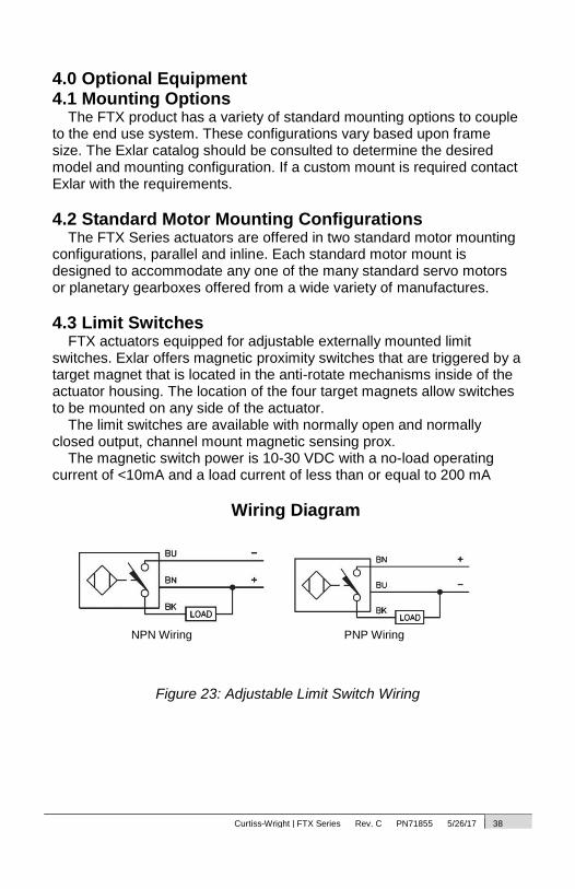
4.3 Limit Switches FTX actuators equipped for adjustable externally mounted limit
switches. Exlar offers magnetic proximity switches that are triggered by a target magnet that is located in the anti-rotate mechanisms inside of the actuator housing. The location of the four target magnets allow switches to be mounted on any side of the actuator.
The limit switches are available with normally open and normally closed output, channel mount magnetic sensing prox.
The magnetic switch power is 10-30 VDC with a no-load operating current of <10mA and a load current of less than or equal to 200 mA
Wiring Diagram
Figure 23: Adjustable Limit Switch Wiring
PNP Wiring NPN Wiring

Curtiss-Wright | FTX Series Rev. C PN71855 5/26/17 39
Configuration of Logic of Standard Switch Option Selections
Option SW1 SW2 SW3
L1 Normally Open,
PNP Not Supplied Not Supplied
L2 Normally Closed,
PNP Normally Closed,
PNP Not Supplied
L3 Normally Open,
PNP Normally Closed,
PNP Normally Closed,
PNP
L4 Normally Open,
NPN Not Supplied Not Supplied
L5 Normally Closed,
NPN Normally Closed,
NPN Not Supplied
L6 Normally Open,
NPN Normally Closed,
NPN Normally Closed,
NPN
Switch Type Exlar Part Number
Supplier Part Number
Normally Closed Switch, PNP 43404 Turck P/N: BIM-UNT-RP6X
Normally Open Switch, PNP 43403 Turck P/N: BIM-UNT-AP6X
Normally Closed Switch, NPN 67635 Turck P/N: BIM-UNT-RN6X
Normally Open Switch, NPN 67634 Turck P/N: BIM-UNT-AN6X
See switch manufacturer’s documentation for additional limit switch
information.

Curtiss-Wright | FTX Series Rev. C PN71855 5/26/17 40
4.4 Rod Ends FTX series actuators are available as standard with male or female
rod ends with Metric threads. Each standard rod end is also equipped with wrench flats to aid in attachment to the load.
4.5 Motors FTX Series actuators are designed to accept many types of standard
electric servo motors or planetary gear reducers that are available through various manufactures. Due to motor size, torque or speed, not all motors or reducers can be mounted to each standard actuator.
4.6 Electronics Electronics and drive amplifiers to match the appropriate motors are
available through the same manufactures that supply the motors. All maintenance and service guidelines contained within the motor manufacture manuals should be followed to avoid service problems associated with the amplifier and motor.
5.0 Specifications 5.1 Life Calculations
The expected life of the roller screw in a FTX actuator is expressed as the linear travel distance that 90% of the screws are expected to meet or exceed before experiencing metal fatigue. This is not a guarantee. For accurate lifetime calculations of a roller screw in a linear application, cubic mean load should be used. Consult the catalog for ratings and formulas associated with life calculations.
5.2 Load, Torque, and Linear Speed Calculations The thrust load applied by the FTX actuator is dependent on the
amount of torque that is applied to the roller screw shaft and the lead of the roller screw within the actuator. It is important to include any gearbox reduction and or drive train belt and pulley reduction into this equation as well. The equation that defines the amount of torque required for a corresponding thrust force is listed in the Exlar catalog. Reference this catalog for torque calculations and ratings.
Curtiss-Wright | FTX Series Rev. C PN71855 5/26/17 41
It is also important to recognize that motor torque will be required to accelerate the inertial components of the system in addition to the thrust. Consult Exlar’s sizing guideline for further details.
The linear speed that the FTX actuator will produce at the end of the output rod is a function of rotational speed of the roller screw shaft and roller screw lead. It is important to include any gearbox reduction and or drive train belt and pulley reduction into this equation as well. Reference the Exlar catalog for ratings and formulas regarding the linear speed of the FTX actuators.
5.3 Load and Speed Ratings Each FTX actuator model has an associated maximum force rating.
The maximum force rating is a value that should never be exceeded either by or applied to the actuator... Consult the Exlar catalog for maximum force ratings.
DO NOT exceed maximum force ratings of the FTX actuators. Doing so can and will cause damage to the
actuator and put the operator at risk of injury.
The speed rating of the actuator is dependent on stroke length and diameter of the roller screw inside the actuator. The maximum rotational screw speed of the FTX actuators should be maintained below the maximum rotational screw speed. Consult the Exlar catalog for maximum rotational speeds.

Curtiss-Wright | FTX Series Rev. C PN71855 5/26/17 42
6.0 Troubleshooting 6.1 Mechanical Problems
This section will provide you with a helpful guideline to troubleshooting various problems that may occur during operation and installation of your FTX actuator.
Symptom/ Problem Possible Cause Problem Solution
Abnormally loud whining
coming from actuator.
Misalignment or Side
Load
Check alignment with application,
remount actuator if necessary.
Remove side load.
Abnormally loud whining
coming from actuator. Improper servo tuning
Consult tuning guidelines for servo
motor and drive.
Actuator motor rotates but
output rod does not
extend or retract.
Belt or inline coupling
failure
Disconnect power to motor, remove
belt cover and inspect belt or inline
coupling. Replace if necessary.
Motor does not operate.
Motor electrical
problem Consult motor manufacturer.
Output rod has excessive
rotation, or rotates but
does not extend. Anti-rotate failure
Replace anti-rotate mechanism
Excessive motor current
to operate actuator.
An internal
mechanism binding,
application binding,
roller screw failure.
Operation over peak
load rating.
Consult Exlar
6.2 Electrical Problems All electrical problems associated with the motor used to drive the
roller screw in an FTX actuator should be taken up with that motor manufacturer. Exlar will assist in contacting the appropriate person.
If an externally mounted limit switch is not operating properly, check all power connections to the switch and make sure that the switch is wired properly. Refer to the diagram in section 4.3 for further details regarding wiring.
Curtiss-Wright | FTX Series Rev. C PN71855 5/26/17 43
6.3 Returning Product for Repair STANDARD EVALUATION AND REPAIR LEADTIME:
Lead-time is dependent upon production capacity and level of demand. Please contact the factory for current lead-time.
EXPEDITED EVALUATION LEADTIME:
An additional charge per unit can be quoted to expedite an evaluation.
Ability to expedite is dependent upon production capacity and level of demand. Please contact the factory for current expedited evaluation lead-time.
PROCEDURE:
Please discuss the return with Exlar Technical Support prior to requesting an RGA number to see if it is possible to resolve the issue prior to return.
If it is determined that an RGA number is required, please do so by completing an online RGA request form located at http://exlar.com/return-authorization-request/ – International Repairs: Closely follow instructions provided by
the Exlar Returned Goods Administrator. Failure to comply with issued instructions may result in delays for repair and return.
Exlar requires a purchase order at the time of RGA; $750 on warranty returns (refunded if warranty status is confirmed by the factory), or for the desired service package charge per unit on all non-warranty units.

Curtiss-Wright | FTX Series Rev. C PN71855 5/26/17 44
7.0 Fastener Torque Specification 7.1 FTX095 Torque Specification
FTX095 Torque Specification
Fastener Description/Size
Part Number
Qty N m ft-lb in-lb Loctite Spec
Gland to Face Plate Screw Screw, M5x0.8 x 22mm, SHCS, SS
48534 4 6 4 56 222MS
Tie Rod Nuts Nut, M10x1.5, SS 11586 4 34 25 - N/A
Motor Plate to Bearing Housing
Screw, M10x1.5 x 30mm, SHCS
10987 4 52 38 - N/A
Idler Assembly Hex Nut Nut, 1/2-13 UNC, Hex 50386 1 47 35 - N/A
Drive Cover to Motor Plate Screw, M8x1.25 x 85mm, SHCS, SS
71592 12 26 19 - 242
Motor Plate Sealing Screw Screw, M6x1.0 x 12mm, SHCS, SS
45593 1 11 8 96 242
Clevis/Eye to Adapter Plate (MP1 and MP3 Option)
Screw, M12x1.75 x 30mm, SHCS, SS
63303 4 60 44 - 242
Clevis/Eye to Adapter Plate (FTC and FTG Option)
Screw, M12x1.75 x 30mm, SHCS, SS
63303 4 60 44 - 242
Inline Housing Screws Screw, M10x1.5 x -----, SHCS, SS
- 4 52 38 - 242
Inline Adapter Plate Screws Screw, M8x1.25 x 20mm, SHCS, SS
38215 4 26 19 228 242
Actuator Shaft to Motor Shaft Coupling
Size 60 Coupling, M6 Screw - 2 15 11 133 N/A
Size 150 Coupling, M10 Screw
- 2 35 25 310 N/A
Trunnion Mounting Screws Screw, M10x1.5 x 25mm, SHCS, SS
51724 8 52 38 - 242
Grease Access Plug Plug, Hex Socket, M16x1.5 70763 1 11 8 96 N/A
Oil Sight Glass Plug Plug, Oil Sight, M16x1.5 70834 2 11 8 96 N/A
Magnetic Oil Fill Plug Plug, Magnetic, M16x1.5 70763 2 11 8 96 N/A
Adapter, 10-32 x 3/16 10-32 x 3/16 70836 2 0.56-0.79
- 5-7 222MS
Oil Port Block Screw Screw, M5x0.8 x 12mm, SHCS, SS
31127 4 6 4.66 56 222MS
1108 Pulley Bushing Screw 1/4-20 x 1/2 N/A - 6 4.66 56 N/A
2012 Pulley Bushing Screw 7/16-14 x 7/8 N/A - 31 23 280 N/A

Curtiss-Wright | FTX Series Rev. C PN71855 5/26/17 45
7.2 FTX125 Torque Specification
FTX125 Torque Specification
Fastener Description/Size Part
Number Qty N m ft-lb in-lb
Loctite Spec
Gland to Face Plate Screw Screw, M6x1.0 x 25mm, SHCS, SS 40146 4 11 8 96 222MS
Tie Rod Nuts Nut, M12x1.75, SS 23511 4 61 45 - N/A
Motor Plate to Bearing Housing
Screw, M12x1.75 x 35mm, SHCS 71020 4 54 40 - N/A
Idler Assembly Hex Nut Nut, 1/2-13 UNC, Hex 50386 1 54 40 - N/A
Drive Cover to Motor Plate Screw, M12x1.75 x 120mm, SHCS, SS
62959 8,12 60 44 - 242
Motor Plate Sealing Screw Screw, M10x1.50 x 16mm, Low Head
63905 1 14 10 120 242
Clevis/Eye to Adapter Plate (MP1 and MP3 Option)
Screw, M12x1.75 x 30mm, SHCS, SS
63303 4 60 44 - 242
Clevis/Eye to Adapter Plate (FTC Option)
Screw, M14x2.0 x 40mm, SHCS, SS
38709 4 68 50 - 242
Inline Housing Screws Screw, M12x1.75 x -----, SHCS, Magni Coat
- 4 87 64 - 242
Inline Adapter Plate Screws Screw, M8x1.25 x 35mm, SHCS, SS
30001 4 26 19 228 242
Actuator Shaft to Motor Shaft Coupling
Size 150 Coupling, M8 Screw
- 2 35 26 310 N/A
Size 300 Coupling, M10 Screw
- 2 70 52 620 N/A
Trunnion Mounting Screws Screw, M12x1.75 x 30mm, SHCS, SS
70890 8 60 44 - 242
Grease Access Plug Plug, Hex Socket, M18x1.5 70882 1 14 10 120 N/A
Oil Sight Glass Plug Plug, Oil Sight, M16x1.5 70834 2 11 8 96 N/A
Magnetic Oil Fill Plug Plug, Magnetic, M16x1.5 70763 2 11 8 96 N/A
Adapter, 10-32 x 3/16 10-32 x 3/16 70836 2
0.56-0.79
- 5-7 222MS
Oil Port Block Screw Screw, M5x0.8 x 12mm, SHCS, SS
31127 4 6 4.66 56 222MS
2012 Pulley Bushing Screw 7/16-14 x 7/8 N/A - 31 23 280 N/A
Trantorque OE Bushing 22mm Bore 70190 - 150 111 - N/A
Trantorque OE Bushing 24mm Bore 65165 - 163 120 - N/A
Trantorque OE Bushing 32mm Bore 65166 - 157 116 - N/A
Trantorque OE Bushing 35mm Bore 71226 - 144 106 - N/A

Curtiss-Wright | FTX Series Rev. C PN71855 5/26/17 46
7.3 FTX215 Torque Specification
FTX215 Torque Specification
Fastener Description/Size Part
Number Qty N m ft-lb in-lb Loctite Spec
Gland to Face Plate Screw Screw, M10x1.5 x 45mm, SHCS, SS
67921 8 52 38 457 222MS
Tie Rod Nuts Nut, M20x2.5 Hex, Magni Coat
69120 4 293 216 - N/A
Motor Plate to Bearing Housing
Screw, M16x2.0 x 40mm, SHCS
22599 8 77 57 - N/A
Screw for 2012 Pulley Bushing
7-16-14 x 7/8 N/A - 31 23 280 N/A
Screw for 3020 Pulley Bushing
5/8-11 x 1 1/4 N/A - 91 67 800 N/A
Idler Assembly Hex Nut Nut, 3/4-10 UNC, Hex 10991 1 271 200 - N/A
Drive Cover to Motor Plate Screw, M16x2.0 x 140mm, SHCS
69284 12 108 80 - 242
Motor Plate Sealing Screw Screw, M12x1.75 x 16mm, BHCS, SS
69058 1 14 10 120 242
Clevis/Eye to Adapter Plate Screw, M24x3.0 x 60mm, SHCS, SS
69321 4 203 150 - 242
Inline Housing Nut Nut, M20x2.5 Hex, Magni Coat
69120 4 136 100 - N/A
Motor Plate to Adapter Plate Screw, M12x1.75 x 30mm, SHCS, SS
63303 8 87 64 774 242
Actuator Shaft to Motor Shaft Coupling
Size 450 Coupling, M12 Screw
- 2 119 88 - N/A
Size 800 Coupling, M16 Screw
- 2 289 213 - N/A
Trunnion Mounting Screws Screw, M16x2.0 x 35mm, SHCS, SS
43933 8 121 89 - N/A
Grease Access Plug Plug, Hex Socket, M27x2.0
69620 1 20 15 180 N/A
Oil Sight Glass Plug Plug, Oil Sight, M20x1.5 69618 2 16 12 144 N/A
Magnetic Oil Fill Plug Plug, Magnetic, M16x1.5 69619 2 11 8 96 N/A
Oil Port Block Screw Screw, M6x1.0 x 12mm, SHCS, SS
45593 4 11 8 96 222MS

Curtiss-Wright | FTX Series Rev. C PN71855 5/26/17 47
7.4 FTP215 Torque Specification
FTP215 Torque Specification
Fastener Description/Size Part
Number Qty N m ft-lb in-lb Loctite Spec
Gland to Face Plate Screw Screw, M10x1.5 x 45mm, SHCS, SS
67921 8 52 38 457 222MS
Tie Rod Nuts Nut, M30x3.5 Hex, Magni Coat
69121 4 575 558 - N/A
Motor Plate to Bearing Housing
Screw, M16x2.0 x 40mm, SHCS
22599 8 77 57 - N/A
Screw for 3020 Pulley Bushing
5/8-11 x 1 1/4 N/A - 91 67 800 N/A
Idler Assembly Hex Nut Nut, 3/4-10 UNC, Hex 10991 1 271 200 - N/A
Drive Cover to Motor Plate Screw, M16x2.0 x 140mm, SHCS
69284 12 108 80 - 242
Motor Plate Sealing Screw Screw, M12x1.75 x 16mm, BHCS, SS
69058 1 14 10 120 242
Inline Housing Nut Nut, M20x2.5 Hex, Magni Coat
69120 4 136 100 - N/A
Motor Plate to Adapter Plate Screw, M12x1.75 x 30mm, SHCS, SS
63303 8 87 64 774 242
Actuator Shaft to Motor Shaft Coupling
Size 800 Coupling, M16 Screw
- 2 289 213 - N/A
Oil Sight Glass Plug Plug, Oil Sight, M20x1.5 69618 2 16 12 144 N/A
Magnetic Oil Fill Plug Plug, Magnetic, M16x1.5 69619 2 11 8 96 N/A
Oil Port Block Screw Screw, M6x1.0 x 12mm, SHCS, SS
45593 4 11 8 96 222MS
Curtiss-Wright | FTX Series Rev. C PN71855 5/26/17 48
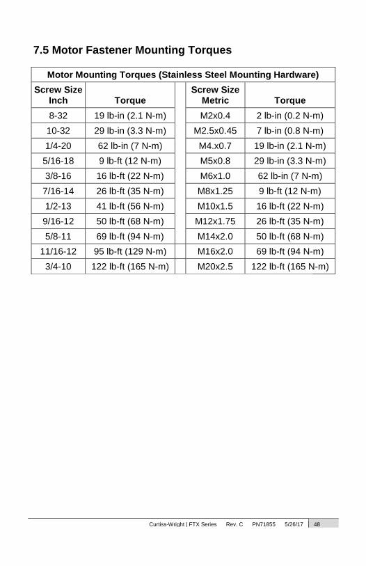
7.5 Motor Fastener Mounting Torques
Motor Mounting Torques (Stainless Steel Mounting Hardware)
Screw Size Inch Torque
Screw Size Metric Torque
8-32 19 lb-in (2.1 N-m) M2x0.4 2 lb-in (0.2 N-m)
10-32 29 lb-in (3.3 N-m) M2.5x0.45 7 lb-in (0.8 N-m)
1/4-20 62 lb-in (7 N-m) M4.x0.7 19 lb-in (2.1 N-m)
5/16-18 9 lb-ft (12 N-m) M5x0.8 29 lb-in (3.3 N-m)
3/8-16 16 lb-ft (22 N-m) M6x1.0 62 lb-in (7 N-m)
7/16-14 26 lb-ft (35 N-m) M8x1.25 9 lb-ft (12 N-m)
1/2-13 41 lb-ft (56 N-m) M10x1.5 16 lb-ft (22 N-m)
9/16-12 50 lb-ft (68 N-m) M12x1.75 26 lb-ft (35 N-m)
5/8-11 69 lb-ft (94 N-m) M14x2.0 50 lb-ft (68 N-m)
11/16-12 95 lb-ft (129 N-m) M16x2.0 69 lb-ft (94 N-m)
3/4-10 122 lb-ft (165 N-m) M20x2.5 122 lb-ft (165 N-m)