Exlar GS Series - TG Drives · 4 952.368.3434 | GS Series Linear Actuators Exlar GS Series Linear...
33
4 952.368.3434 | www.exlar.com GS Series Linear Actuators Exlar GS Series Linear Actuator Family The GS Series linear actuator family offers you two grades of actuator to provide cost effective options in order to meet your application’s requirements. View the chart below to compare the GSX and GSM models. All GS Series actuators use a specially designed roller screw mechanism for converting electric motor power into linear motion within the actuator. Planetary rollers assembled around the actuator’s extending rod follow threads which are precisely machined on the inside surface of the actuator’s hollow armature. Linear motion is produced in precise synchronization with the armature rotation. Because this roller screw mechanism has an inherently larger cumulative contact surface, these actuators have a much longer working life, and can handle heavier loads at higher speeds than is possible from a similarly sized unit built around a ball screw system. Exlar’s T-LAM segmented lamination stator technology delivers higher continuous motor torque than is available in traditionally wound motors. T-LAM technology consists of stator segments, each containing individual phase wiring for maximum motor performance. The improved efficiencies of the GSX Series are a result of the limited heat generation qualities inherent in the segmented stator design as seen above. The elimination of end turns in the stator, and use of thermally conductive potting removes the parts most susceptible to failure in a traditional stator. Other design advantages include: • Neodymium-iron-boron magnets provide high flux density and maximum motor torque. • Thermally conductive potting of the entire stator provides increased heat dissipation and provides protection from contamination in oil-cooled units. • Each stator segment contains individual phase wiring. External winding of individual segments provides maximum slot fill for maximum motor performance. • Motors with T-LAM technology have Class 180 H insulation systems compliant with UL requirements. UL recognized component. • Motors with T-LAM technology are CE compliant The Actuator & Motor, All in one Compact Unit With other actuator technologies, customers are usually responsible for engineering the completed linear motion system. This usually includes purchasing the motor, gear reducer, timing belt, mounting hardware, flexible couplings, etc. separately. Then they all must be assembled to perform properly in a given application. GS Series actuators eliminate all this systems engineering. These units are single, fully integrated component packages – much smaller than traditional rotary-to-linear conversion mechanisms. Designed for Closed Loop Servo Systems Their brushless servo design means GS Series units can be used in advanced closed-loop servo systems when velocity and positioning is required. Position feedback can be delivered in a number of different firms. These include resolvers, encoders or internally mounted linear position feedback sensors. GSX and GSM Differences GSX (pg 4) GSM (pg 38) Ingress Protection IP65 IP54 (IP65 optional) No. of Stacks 1, 2, 3 1, 2 Life BSY (Ball Screw Years) 15X 2 to 5X Oil Cooling Yes No Food Grade Paint Yes No Electroless Nickel Housing Yes No Stainless Steel Case Yes No Hard Coat Anodized Yes Yes LVDT FB Yes (except 2" frame) Yes (except 2" frame) 5.5 in. Frame Yes No 7 in. Frame Yes No Force (lbf ) 92 - 15,000 92 - 3,966 1.0 Lead 50 & 60 only No Rear Brake all all Speeds (ips) 5 - 40 5 - 37.5 Electroless Nickel Connectors Yes Yes Lamination Endcaps Individual Segments
Transcript of Exlar GS Series - TG Drives · 4 952.368.3434 | GS Series Linear Actuators Exlar GS Series Linear...
4 952.368.3434 | www.exlar.com
GS Series Linear Actuators
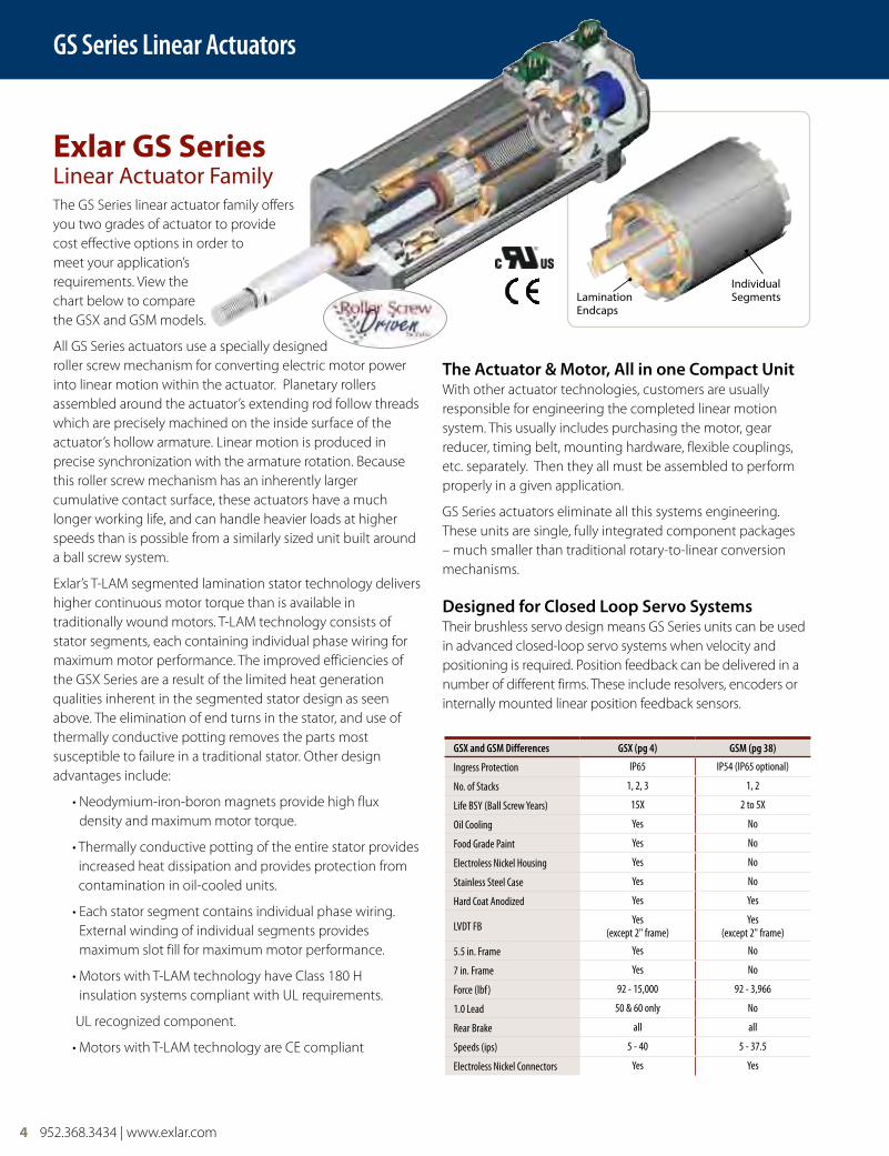
Exlar GS Series Linear Actuator FamilyThe GS Series linear actuator family offers you two grades of actuator to provide cost effective options in order to meet your application’s requirements. View the chart below to compare the GSX and GSM models.
All GS Series actuators use a specially designed roller screw mechanism for converting electric motor power into linear motion within the actuator. Planetary rollers assembled around the actuator’s extending rod follow threads which are precisely machined on the inside surface of the actuator’s hollow armature. Linear motion is produced in precise synchronization with the armature rotation. Because this roller screw mechanism has an inherently larger cumulative contact surface, these actuators have a much longer working life, and can handle heavier loads at higher speeds than is possible from a similarly sized unit built around a ball screw system.
Exlar’s T-LAM segmented lamination stator technology delivers higher continuous motor torque than is available in traditionally wound motors. T-LAM technology consists of stator segments, each containing individual phase wiring for maximum motor performance. The improved efficiencies of the GSX Series are a result of the limited heat generation qualities inherent in the segmented stator design as seen above. The elimination of end turns in the stator, and use of thermally conductive potting removes the parts most susceptible to failure in a traditional stator. Other design advantages include:
• Neodymium-iron-boron magnets provide high flux density and maximum motor torque.
• Thermally conductive potting of the entire stator provides increased heat dissipation and provides protection from contamination in oil-cooled units.
• Each stator segment contains individual phase wiring. External winding of individual segments provides maximum slot fill for maximum motor performance.
• Motors with T-LAM technology have Class 180 H insulation systems compliant with UL requirements.
UL recognized component.
• Motors with T-LAM technology are CE compliant
The actuator & Motor, all in one compact unitWith other actuator technologies, customers are usually responsible for engineering the completed linear motion system. This usually includes purchasing the motor, gear reducer, timing belt, mounting hardware, flexible couplings, etc. separately. Then they all must be assembled to perform properly in a given application.
GS Series actuators eliminate all this systems engineering. These units are single, fully integrated component packages – much smaller than traditional rotary-to-linear conversion mechanisms.
designed for closed loop Servo SystemsTheir brushless servo design means GS Series units can be used in advanced closed-loop servo systems when velocity and positioning is required. Position feedback can be delivered in a number of different firms. These include resolvers, encoders or internally mounted linear position feedback sensors.
GSX and GSM Differences GSX (pg 4) GSM (pg 38)
Ingress Protection IP65 IP54 (IP65 optional)
No. of Stacks 1, 2, 3 1, 2
Life BSY (Ball Screw Years) 15X 2 to 5X
Oil Cooling Yes No
Food Grade Paint Yes No
Electroless Nickel Housing Yes No
Stainless Steel Case Yes No
Hard Coat Anodized Yes Yes
LVDT FB Yes(except 2" frame)
Yes(except 2" frame)
5.5 in. Frame Yes No
7 in. Frame Yes No
Force (lbf) 92 - 15,000 92 - 3,966
1.0 Lead 50 & 60 only No
Rear Brake all all
Speeds (ips) 5 - 40 5 - 37.5
Electroless Nickel Connectors Yes Yes
Lamination Endcaps
Individual Segments
GSX Series Linear Actuators
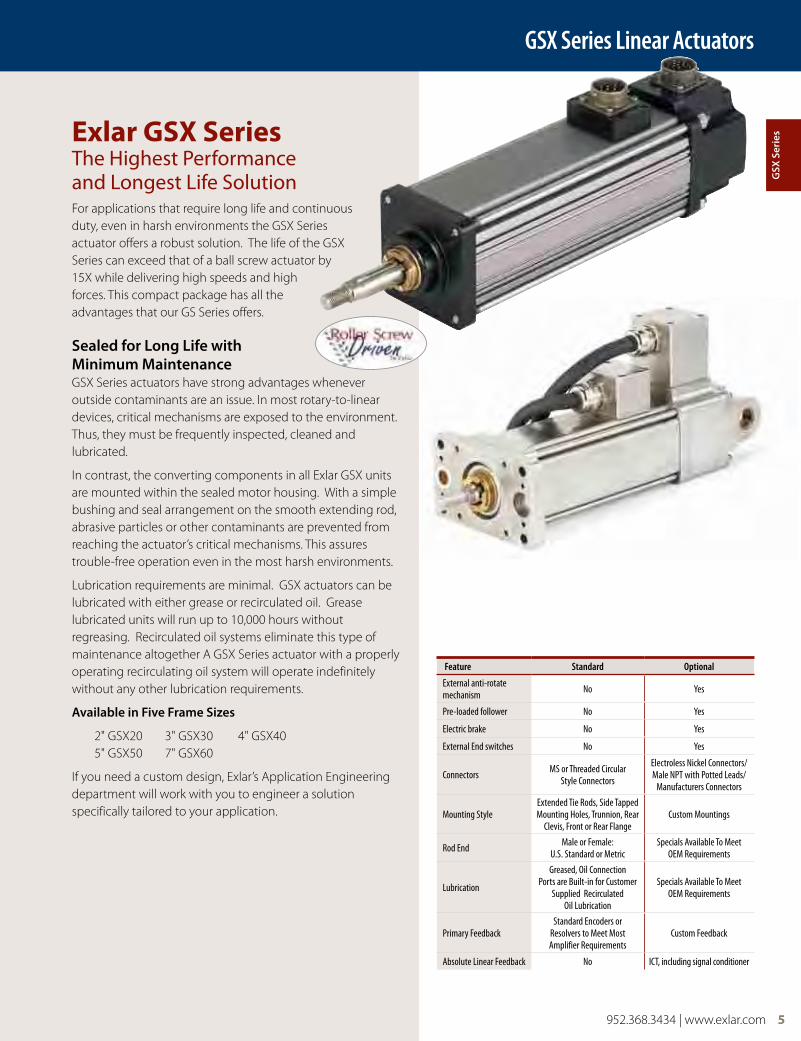
Exlar GSX Series The Highest Performance and Longest Life SolutionFor applications that require long life and continuous duty, even in harsh environments the GSX Series actuator offers a robust solution. The life of the GSX Series can exceed that of a ball screw actuator by 15X while delivering high speeds and high forces. This compact package has all the advantages that our GS Series offers.
Sealed for long life with Minimum MaintenanceGSX Series actuators have strong advantages whenever outside contaminants are an issue. In most rotary-to-linear devices, critical mechanisms are exposed to the environment. Thus, they must be frequently inspected, cleaned and lubricated.
In contrast, the converting components in all Exlar GSX units are mounted within the sealed motor housing. With a simple bushing and seal arrangement on the smooth extending rod, abrasive particles or other contaminants are prevented from reaching the actuator’s critical mechanisms. This assures trouble-free operation even in the most harsh environments.
Lubrication requirements are minimal. GSX actuators can be lubricated with either grease or recirculated oil. Grease lubricated units will run up to 10,000 hours without regreasing. Recirculated oil systems eliminate this type of maintenance altogether A GSX Series actuator with a properly operating recirculating oil system will operate indefinitely without any other lubrication requirements.
available in Five Frame Sizes
2" GSX20 3" GSX30 4" GSX40 5" GSX50 7" GSX60
If you need a custom design, Exlar’s Application Engineering department will work with you to engineer a solution specifically tailored to your application.
Feature Standard Optional
External anti-rotate mechanism No Yes
Pre-loaded follower No Yes
Electric brake No Yes
External End switches No Yes
Connectors MS or Threaded CircularStyle Connectors
Electroless Nickel Connectors/Male NPT with Potted Leads/
Manufacturers Connectors
Mounting StyleExtended Tie Rods, Side Tapped Mounting Holes, Trunnion, Rear
Clevis, Front or Rear FlangeCustom Mountings
Rod End Male or Female: U.S. Standard or Metric
Specials Available To Meet OEM Requirements
Lubrication
Greased, Oil Connection Ports are Built-in for Customer
Supplied Recirculated Oil Lubrication
Specials Available To Meet OEM Requirements
Primary FeedbackStandard Encoders or
Resolvers to Meet Most Amplifier Requirements
Custom Feedback
Absolute Linear Feedback No ICT, including signal conditioner
952.368.3434 | www.exlar.com 5
gSX
Ser
ies
6 952.368.3434 | www.exlar.com
GSX Series Linear Actuators
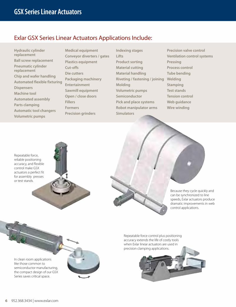
Repeatable force control plus positioning accuracy extends the life of costly tools when Exlar linear actuators are used in precision clamping applications.
hydraulic cylinder replacementball screw replacementPneumatic cylinder replacementchip and wafer handlingautomated flexible fixturingdispensersMachine toolautomated assemblyParts clampingautomatic tool changersvolumetric pumps
Medical equipmentconveyor diverters / gatesPlastics equipmentcut-offsdie cuttersPackaging machineryentertainmentSawmill equipmentopen / close doorsFillersFormersPrecision grinders
Indexing stagesliftsProduct sortingMaterial cuttingMaterial handlingRiveting / fastening / joiningMoldingvolumetric pumpsSemiconductorPick and place systemsRobot manipulator armsSimulators
Precision valve controlventilation control systemsPressingProcess controlTube bendingweldingStampingTest standsTension controlweb guidancewire winding
Exlar GSX Series Linear Actuators Applications Include:
In clean room applications like those common to semiconductor manufacturing, the compact design of our GSX Series saves critical space.
Because they cycle quickly and can be synchronized to line speeds, Exlar actuators produce dramatic improvements in web control applications.
Repeatable force, reliable positioning accuracy, and flexible control make GSX actuators a perfect fit for assembly presses or test stands.
952.368.3434 | www.exlar.com 7
GSX Series Linear Actuators
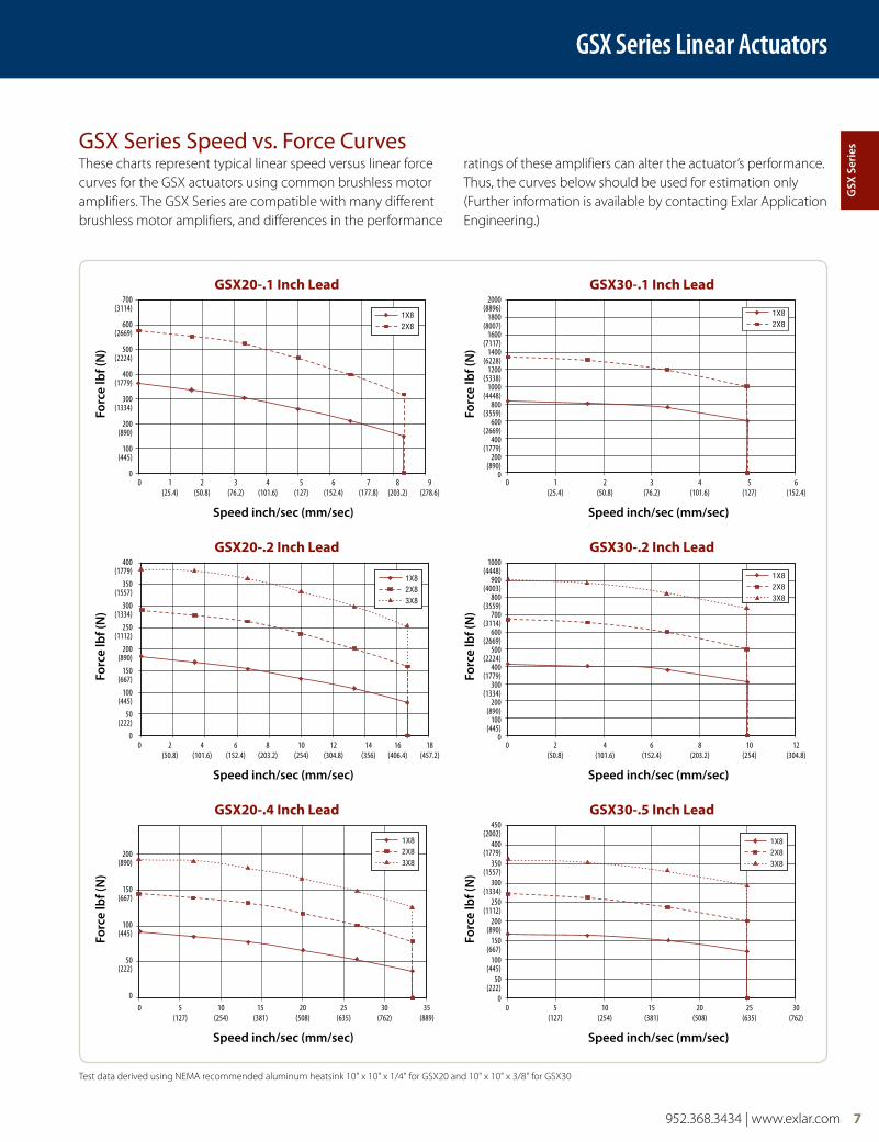
These charts represent typical linear speed versus linear force curves for the GSX actuators using common brushless motor amplifiers. The GSX Series are compatible with many different brushless motor amplifiers, and differences in the performance
ratings of these amplifiers can alter the actuator’s performance. Thus, the curves below should be used for estimation only (Further information is available by contacting Exlar Application Engineering.)
1X82X8
1X82X83X8
700 (3114)
600 (2669)
500 (2224)
400 (1779)
300 (1334)
200 (890)
100 (445)
0
400 (1779)
350 (1557)
300 (1334)
250 (1112)
200 (890)
150 (667)
100 (445)
50 (222)
0
200 (890)
150 (667)
100 (445)
50 (222)
0
Speed inch/sec (mm/sec)
Speed inch/sec (mm/sec)
Speed inch/sec (mm/sec)
Speed inch/sec (mm/sec)
Speed inch/sec (mm/sec)
Speed inch/sec (mm/sec)
Forc
e lb
f (n
)Fo
rce
lbf (
n)
Forc
e lb
f (n
)
Forc
e lb
f (n
)Fo
rce
lbf (
n)
Forc
e lb
f (n
)
GSX20-.1 Inch Lead
GSX20-.2 Inch Lead
GSX20-.4 Inch Lead
GSX30-.1 Inch Lead
GSX30-.2 Inch Lead
GSX30-.5 Inch Lead
0 1 2 3 4 5 6 7 8 9 (25.4) (50.8) (76.2) (101.6) (127) (152.4) (177.8) (203.2) (278.6)
0 2 4 6 8 10 12 14 16 18 (50.8) (101.6) (152.4) (203.2) (254) (304.8) (356) (406.4) (457.2)
0 5 10 15 20 25 30 35 (127) (254) (381) (508) (635) (762) (889)
GSX Series Speed vs. Force Curves
0 1 2 3 4 5 6 (25.4) (50.8) (76.2) (101.6) (127) (152.4)
0 2 4 6 8 10 12 (50.8) (101.6) (152.4) (203.2) (254) (304.8)
0 5 10 15 20 25 30 (127) (254) (381) (508) (635) (762)
2000 (8896)
1800 (8007)
1600 (7117)
1400 (6228)
1200 (5338)
1000 (4448)
800 (3559)
600 (2669)
400 (1779)
200 (890)
0
1000(4448)
900(4003)
800(3559)
700(3114)
600(2669)
500(2224)
400(1779)
300(1334)
200(890)
100(445)
0
450 (2002)
400 (1779)
350 (1557)
300 (1334)
250 (1112)
200 (890)
150 (667)
100 (445)
50 (222)
0
Test data derived using NEMA recommended aluminum heatsink 10" x 10" x 1/4" for GSX20 and 10" x 10" x 3/8" for GSX30
gSX
Ser
ies
8 952.368.3434 | www.exlar.com
GSX Series Linear Actuators
6000 (26689)
5000 (22241)
4000 (17793)
3000 (13345)
2000 (8896)
1000 (4448)
0
Speed inch/sec (mm/sec) Speed inch/sec (mm/sec)
Forc
e lb
f (n
)
Forc
e lb
f (n
)
GSX40-.1 Inch Lead GSX50-.1 Inch Lead
1X82X8
0 1 2 3 4 5 6 (25.4) (50.8) (76.2) (101.6) (127) (152.4)
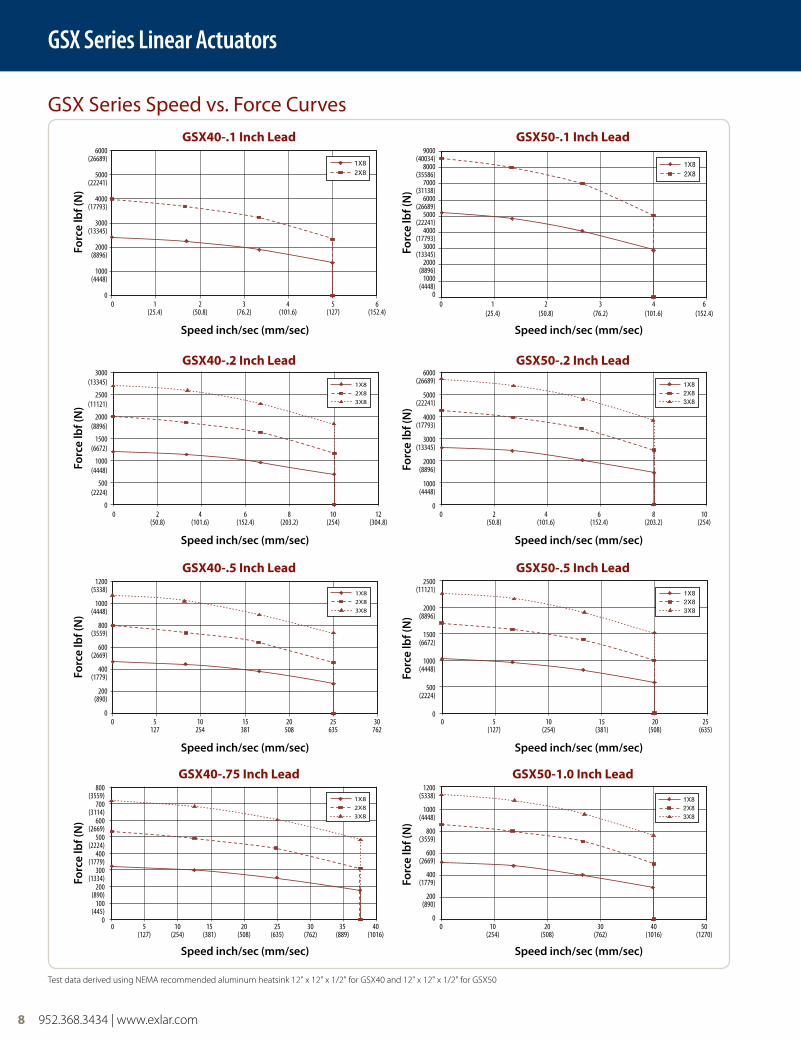
GSX Series Speed vs. Force Curves
0 1 2 3 4 6 (25.4) (50.8) (76.2) (101.6) (152.4)
9000(40034)
8000(35586)
7000(31138)
6000(26689)
5000(22241)
4000(17793)
3000(13345)
2000(8896)
1000(4448)
0
1X82X83X8
Speed inch/sec (mm/sec) Speed inch/sec (mm/sec)
Forc
e lb
f (n
)
Forc
e lb
f (n
)
GSX40-.2 Inch Lead GSX50-.2 Inch Lead
1X82X83X8
0 2 4 6 8 10 12 (50.8) (101.6) (152.4) (203.2) (254) (304.8)
0 2 4 6 8 10 (50.8) (101.6) (152.4) (203.2) (254)
3000 (13345)
2500 (11121)
2000 (8896)
1500 (6672)
1000 (4448)
500 (2224)
0
6000 (26689)
5000 (22241)
4000 (17793)
3000 (13345)
2000 (8896)
1000 (4448)
0
1X82X83X8
1200 (5338)
1000 (4448)
800 (3559)
600 (2669)
400 (1779)
200 (890)
0
Speed inch/sec (mm/sec) Speed inch/sec (mm/sec)
Forc
e lb
f (n
)
Forc
e lb
f (n
)
GSX40-.5 Inch Lead GSX50-.5 Inch Lead
1X82X83X8
0 5 10 15 20 25 30 127 254 381 508 635 762
0 5 10 15 20 25 (127) (254) (381) (508) (635)
2500 (11121)
2000 (8896)
1500 (6672)
1000 (4448)
500 (2224)
0
1X82X83X8
800 (3559)
700 (3114)
600 (2669)
500 (2224)
400 (1779)
300 (1334)
200 (890)
100 (445)
0
Speed inch/sec (mm/sec) Speed inch/sec (mm/sec)
Forc
e lb
f (n
)
Forc
e lb
f (n
)
GSX40-.75 Inch Lead GSX50-1.0 Inch Lead
1X82X83X8
0 5 10 15 20 25 30 35 40 (127) (254) (381) (508) (635) (762) (889) (1016)
0 10 20 30 40 50 (254) (508) (762) (1016) (1270)
1200 (5338)
1000 (4448)
800 (3559)
600 (2669)
400 (1779)
200 (890)
0
Test data derived using NEMA recommended aluminum heatsink 12" x 12" x 1/2" for GSX40 and 12" x 12" x 1/2" for GSX50
952.368.3434 | www.exlar.com 9
GSX Series Linear Actuators
GSX Series Speed vs. Force Curves
Speed inch/sec (mm/sec)
Forc
e lb
f (n
)
GSX60-.25 Inch Lead
1X82X83X8
0 2 4 6 8 10 12 (50.8) (101.6) (152.4) (203.2) (254) (304.8)
14000 (62275)
12000 (53379)
10000 (44482)
8000 (35586)
6000 (26689)
4000 (17793)
2000 (8896)
0
Speed inch/sec (mm/sec)
Forc
e lb
f (n
)
GSX60-.5 Inch Lead
1X82X83X8
0 5 10 15 20 25 (127) (254) (381) (508) (635)
7000 (31138)
6000 (26689)
5000 (22241)
4000 (17793)
3000 (13345)
2000 (8896)
1000 (4448)
0
Speed inch/sec (mm/sec)
Forc
e lb
f (n
)
GSX60-1.0 Inch Lead
1X82X83X8
0 10 20 30 40 50 (254) (508) (762) (1016) (1270)
3500(15569)
3000(13345)
2500(11121)
2000(8896)
1500(6672)
1000(4448)
500(2224)
0
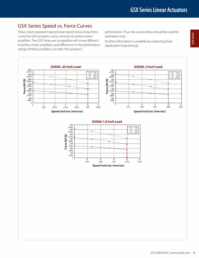
These charts represent typical linear speed versus linear force curves for GSX actuators using common brushless motor amplifiers. The GSX Series are compatible with many different brushless motor amplifiers, and differences in the performance ratings of these amplifiers can alter the actuator’s
performance. Thus, the curves below should be used for estimation only.
(Further information is available by contacting Exlar Application Engineering.)
gSX
Ser
ies
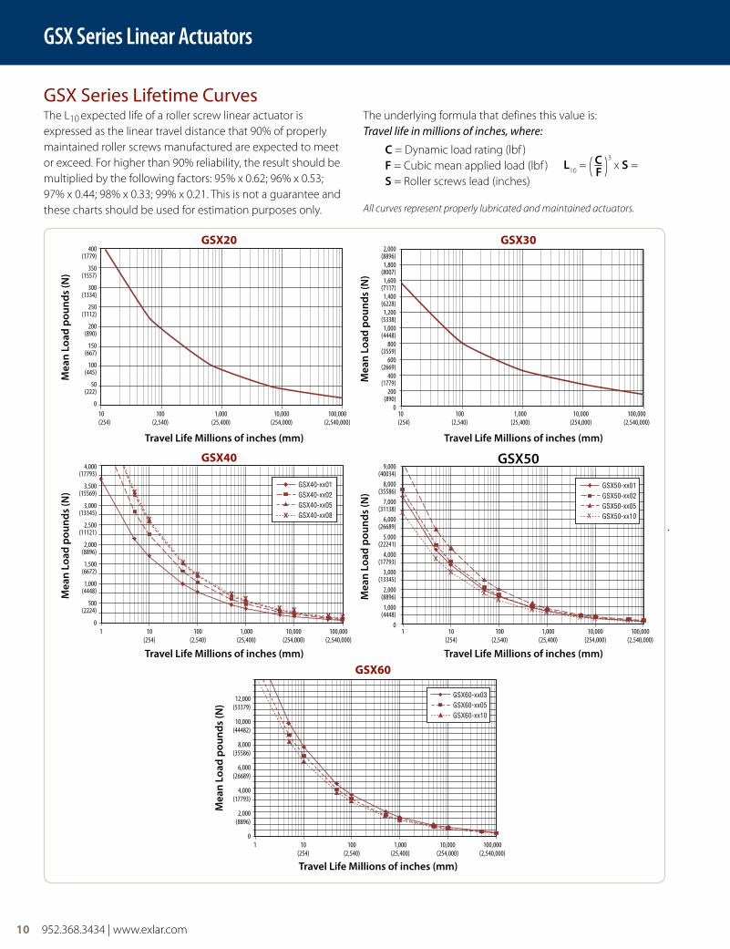
The L10 expected life of a roller screw linear actuator is
expressed as the linear travel distance that 90% of properly maintained roller screws manufactured are expected to meet or exceed. For higher than 90% reliability, the result should be multiplied by the following factors: 95% x 0.62; 96% x 0.53; 97% x 0.44; 98% x 0.33; 99% x 0.21. This is not a guarantee and these charts should be used for estimation purposes only.
The underlying formula that defines this value is: Travel life in millions of inches, where:
c = Dynamic load rating (lbf ) F = Cubic mean applied load (lbf ) S = Roller screws lead (inches)
All curves represent properly lubricated and maintained actuators.
GSX Series Lifetime Curves
10 952.368.3434 | www.exlar.com
GSX40-xx01GSX40-xx02GSX40-xx05GSX40-xx08x
x x x
x x
x
x x
x
x
4,000 (17793)
3,500 (15569)
3,000 (13345)
2,500 (11121)
2,000 (8896)
1,500 (6672)
1,000 (4448)
500 (2224)
01 10 100 1,000 10,000 100,000 (254) (2,540) (25,400) (254,000) (2,540,000)
Travel life Millions of inches (mm)
Mea
n lo
ad p
ound
s (n
)
GSX40
400 (1779)
350 (1557)
300 (1334)
250 (1112)
200 (890)
150 (667)
100 (445)
50 (222)
010 100 1,000 10,000 100,000(254) (2,540) (25,400) (254,000) (2,540,000)
Travel life Millions of inches (mm)
Mea
n lo
ad p
ound
s (n
)
GSX20
GSX60-xx03GSX60-xx05GSX60-xx10
12,000 (53379)
10,000 (44482)
8,000 (35586)
6,000 (26689)
4,000 (17793)
2,000 (8896)
01 10 100 1,000 10,000 100,000 (254) (2,540) (25,400) (254,000) (2,540,000)
Travel life Millions of inches (mm)
Mea
n lo
ad p
ound
s (n
)
GSX60
2,000 (8896)1,800
(8007)1,600
(7117)1,400
(6228)1,200
(5338)1,000
(4448)800
(3559)600
(2669)400
(1779)200
(890)0
10 100 1,000 10,000 100,000(254) (2,540) (25,400) (254,000) (2,540,000)
Travel life Millions of inches (mm)
Mea
n lo
ad p
ound
s (n
)
GSX30
GSX50-xx01GSX50-xx02GSX50-xx05GSX50-xx10xx
xx
xx
x x x x x
9,000 (40034)
8,000 (35586)
7,000 (31138)
6,000 (26689)
5.000 (22241)
4,000 (17793)
3,000 (13345)
2,000 (8896)1,000
(4448)0
1 10 100 1,000 10,000 100,000 (254) (2,540) (25,400) (254,000) (2,540,000)
Travel life Millions of inches (mm)
Mea
n lo
ad p
ound
s (n
)
gSX50
GSX Series Linear Actuators
l10
= ( c )3 x S =
F
952.368.3434 | www.exlar.com 11
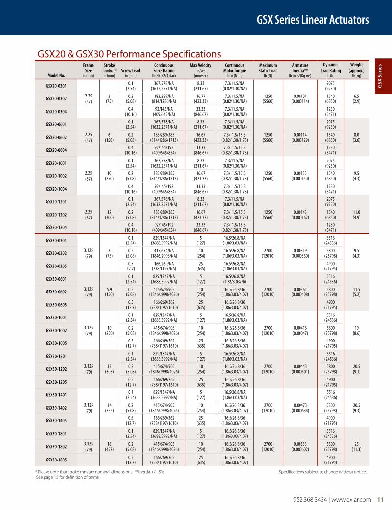
GSX20 & GSX30 Performance Specifications
Model No.
Frame Size
in (mm)
Stroke(nominal)*
in (mm)Screw Lead
in (mm)
Continuous Force Rating
lb (N) 1/2/3 stack
Max Velocityin/sec
(mm/sec)
ContinuousMotor Torque
lb-in (N-m)
Maximum Static Load
lb (N)
Armature Inertia**
lb-in-s2 (Kg-m2)
Dynamic Load Rating
lb (N)
Weight (approx.)
lb (kg)
GSX20-0301
2.25(57)
3(75)
0.1(2.54)
367/578/NA(1632/2571/NA)
8.33(211.67)
7.3/11.5/NA (0.82/1.30/NA)
1250(5560)
0.00101(0.000114)
2075(9230)
6.5(2.9)GSX20-0302 0.2
(5.08)183/289/NA
(814/1286/NA)16.77
(423.33)7.3/11.5/NA
(0.82/1.30/NA)1540
(6850)
GSX20-0304 0.4(10.16)
92/145/NA(409/645/NA)
33.33(846.67)
7.3/11.5/NA (0.82/1.30/NA)
1230(5471)
GSX20-0601
2.25(57)
6(150)
0.1(2.54)
367/578/NA(1632/2571/NA)
8.33(211.67)
7.3/11.5/NA (0.82/1.30/NA)
1250(5560)
0.00114(0.000129)
2075(9230)
8.0(3.6)GSX20-0602 0.2
(5.08)183/289/385
(814/1286/1713)16.67
(423.33)7.3/11.5/15.3
(0.82/1.30/1.73)1540
(6850)
GSX20-0604 0.4(10.16)
92/145/192(409/645/854)
33.33(846.67)
7.3/11.5/15.3 (0.82/1.30/1.73)
1230(5471)
GSX20-1001
2.25(57)
10(250)
0.1(2.54)
367/578/NA(1632/2571/NA)
8.33(211.67)
7.3/11.5/NA (0.82/1.30/NA)
1250(5560)
0.00133(0.000150)
2075(9230)
9.5(4.3)GSX20-1002 0.2
(5.08)183/289/385
(814/1286/1713)16.67
(423.33)7.3/11.5/15.3
(0.82/1.30/1.73)1540
(6850)
GSX20-1004 0.4(10.16)
92/145/192(409/645/854)
33.33(846.67)
7.3/11.5/15.3 (0.82/1.30/1.73)
1230(5471)
GSX20-1201
2.25(57)
12(300)
0.1(2.54)
367/578/NA(1632/2571/NA)
8.33(211.67)
7.3/11.5/NA (0.82/1.30/NA)
1250(5560)
0.00143(0.000162)
2075(9230)
11.0(4.9)GSX20-1202 0.2
(5.08)183/289/385
(814/1286/1713)16.67
(423.33)7.3/11.5/15.3
(0.82/1.30/1.73)1540
(6850)
GSX20-1204 0.4(10.16)
92/145/192(409/645/854)
33.33(846.67)
7.3/11.5/15.3 (0.82/1.30/1.73)
1230(5471)
GSX30-0301
3.125(79)
3(75)
0.1(2.54)
829/1347/NA(3688/5992/NA)
5(127)
16.5/26.8/NA (1.86/3.03/NA)
2700(12010)
0.00319(0.000360)
5516(24536)
9.5(4.3)GSX30-0302 0.2
(5.08)415/674/NA
(1846/2998/NA)10
(254)16.5/26.8/NA
(1.86/3.03/NA)5800
(25798)
GSX30-0305 0.512.7)
166/269/NA(738/1197/NA)
25(635)
16.5/26.8/NA (1.86/3.03/NA)
4900(21795)
GSX30-0601
3.125(79)
5.9(150)
0.1(2.54)
829/1347/NA(3688/5992/NA)
5(127)
16.5/26.8/NA (1.86/3.03/NA
2700(12010)
0.00361(0.000408)
5516(24536)
11.5(5.2)GSX30-0602 0.2
(5.08)415/674/905
(1846/2998/4026)10
(254)16.5/26.8/36
(1.86/3.03/4.07)5800
(25798)
GSX30-0605 0.5(12.7)
166/269/362(738/1197/1610)
25(635)
16.5/26.8/36 (1.86/3.03/4.07)
4900(21795)
GSX30-1001
3.125(79)
10(250)
0.1(2.54)
829/1347/NA(3688/5992/NA)
5(127)
16.5/26.8/NA (1.86/3.03/NA)
2700(12010)
0.00416(0.00047)
5516(24536)
19(8.6)GSX30-1002 0.2
(5.08)415/674/905
(1846/2998/4026)10
(254)16.5/26.8/36
(1.86/3.03/4.07)5800
(25798)
GSX30-1005 0.5(12.7)
166/269/362(738/1197/1610)
25(635)
16.5/26.8/36 (1.86/3.03/4.07)
4900(21795)
GSX30-1201
3.125(79)
12(305)
0.1(2.54)
829/1347/NA(3688/5992/NA)
5(127)
16.5/26.8/NA (1.86/3.03/NA)
2700(12010)
0.00443(0.000501)
5516(24536)
20.5(9.3)GSX30-1202 0.2
(5.08)415/674/905
(1846/2998/4026)10
(254)16.5/26.8/36
(1.86/3.03/4.07)5800
(25798)
GSX30-1205 0.5(12.7)
166/269/362(738/1197/1610)
25(635)
16.5/26.8/36 (1.86/3.03/4.07)
4900(21795)
GSX30-1401
3.125(79)
14(355)
0.1(2.54)
829/1347/NA(3688/5992/NA)
5(127)
16.5/26.8/NA (1.86/3.03/NA)
2700(12010)
0.00473(0.000534)
5516(24536)
20.5(9.3)GSX30-1402 0.2
(5.08)415/674/905
(1846/2998/4026)10
(254)16.5/26.8/36
(1.86/3.03/4.07)5800
(25798)
GSX30-1405 0.5(12.7)
166/269/362(738/1197/1610)
25(635)
16.5/26.8/36 (1.86/3.03/4.07)
4900(21795)
GSX30-1801
18(457)
0.1(2.54)
829/1347/NA(3688/5992/NA)
5(127)
16.5/26.8/36 (1.86/3.03/4.07)
2700(12010)
0.00533(0.000602)
5516(24536)
25(11.3)GSX30-1802 3.125
(79)0.2
(5.08)415/674/905
(1846/2998/4026)10
(254)16.5/26.8/36
(1.86/3.03/4.07)5800
(25798)
GSX30-1805 0.5(12.7)
166/269/362(738/1197/1610)
25(635)
16.5/26.8/36 (1.86/3.03/4.07)
4900(21795)
* Please note that stroke mm are nominal dimensions. **Inertia +/– 5% Specifications subject to change without notice. See page 13 for definition of terms.
GSX Series Linear Actuators
gSX
Ser
ies

12 952.368.3434 | www.exlar.com
GSX40 Series Linear Actuators
GSX40 Performance Specifications
Model No.Frame Size
in (mm)
Stroke(nominal)*
in (mm)Screw Lead
in (mm)
Continuous Force Rating
lb (N) 1/2/3 stackMax Velocityin/sec (mm/sec)
ContinuousMotor Torque
lb-in (N-m)
Maximum Static Load
lb (N)
Armature Inertia**
lb-in-s2 (Kg-m2)
Dynamic Load Rating
lb (N)
Weight (approx.)
lb (kg)
GSX40-0601
3.9(99)
6(150)
0.1 (2.54)
2393/3966/NA (10645/17642/NA)
5 (127)
47.6/78.9/NA (5.38/8.91/NA)
5400 (24020)
0.0152 ( 0.001717)
7900 (35141)
20 (9.1)
GSX40-0602 0.2(5.08)
1196/1983/NA (5320/8821/NA)
10 (254)
8300 (36920)
GSX40-0605 0.5 (12.7)
479/793/NA (2131/3527/NA)
25 (635)
7030 (31271)
GSX40-0608 0.75(19.05)
319/529/NA (1419/2353/NA)
37.5 (953)
6335 (28179)
GSX40-0801
3.9(99)
8(200)
0.1 (2.54)
2393/3966/NA (10645/17642/NA)
5 (127)
47.6/78.9/107.1 (5.38/8.91/12.1)
5400 (24020)
0.0163 ( 0.001842)
7900 (35141)
24 (10.9)
GSX40-0802 0.2(5.08)
1196/1983/2692 (5320/8821/11975)
10 (254)
8300 (36920)
GSX40-0805 0.5(12.7)
479/793/1077 (2131/3527/4791)
25 (635)
7030 (31271)
GSX40-0808 0.75 (19.05)
319/529/718 (1419/2353/3194)
37.5(953)
6335 (28179)
GSX40-1001
3.9(99)
10(250)
0.1 (2.54)
2393/3966/NA (10645/17642/NA)
5 (127)
47.6/78.9/107.1 (5.38/8.91/12.1)
5400(24020)
0.0175 (0.001977)
7900 (35141)
28 (12.7)
GSX40-1002 0.2 (5.08)
1196/1983/2692 (5320/8821/11975)
10 (254)
8300 (36920)
GSX40-1005 0.5 (12.7)
479/793/1077 (2131/3527/4791)
25 (635)
7030 (31271)
GSX40-1008 0.75 (19.05)
319/529/718 (1419/2353/3194)
37.5 (953)
6335 (28179)
GSX40-1201
3.9 (99)
12 (305)
0.1(2.54)
2393/3966/NA (10645/17642/NA)
5 (127)
47.6/78.9/107.1 (5.38/8.91/12.1)
5400 (24020)
0.0186 ( 0.002102)
7900 (35141)
32 (14.5)
GSX40-1202 0.2 (5.08)
1196/1983/2692 (5320/8821/11975)
10 (254)
8300 (36920)
GSX40-1205 0.5 (12.7)
479/793/1077 (2131/3527/4791)
25 (635)
7030 (31271)
GSX40-1208 0.75 (19.05)
319/529/718 (1419/2353/3194)
37.5 (953)
6335 (28179)
GSX40-1801
3.9 (99)
18 (457)
0.1 (2.54)
2393/3966/NA (10645/17642/NA)
5 (127)
47.6/78.9/107.1 (5.38/8.91/12.1)
5400 (24020)
0.022 (0.002486)
7900 (35141)
44 (20)GSX40-1802 0.2
(5.08)1196/1983/2692
(5320/8821/11975)10
(254)8300
(36920)
GSX40-1805 0.5 (12.7)
479/793/1077 (2131/3527/4791)
25 (635)
7030(31271)
* Please note that stroke mm are nominal dimensions. **Inertia +/– 5% Specifications subject to change without notice. See page 13 for definition of terms.
952.368.3434 | www.exlar.com 13
GSX50 & GSX60 Series Linear Actuators
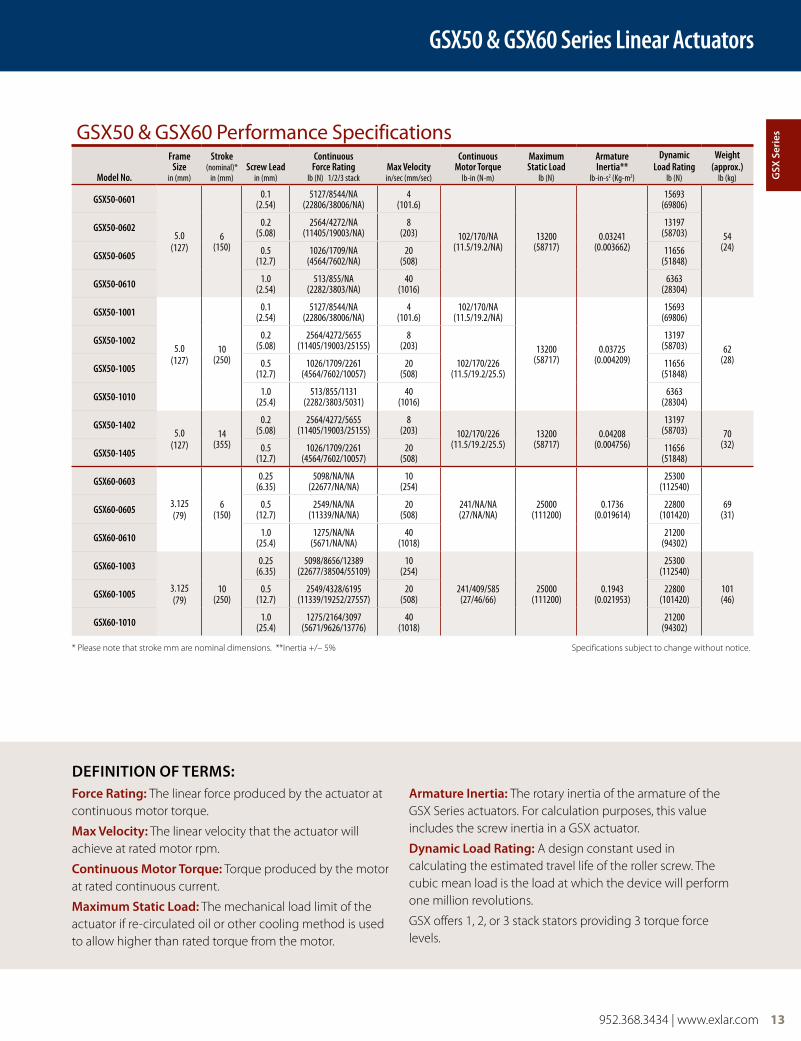
GSX50 & GSX60 Performance Specifications
Model No.
Frame Size
in (mm)
Stroke(nominal)*
in (mm)Screw Lead
in (mm)
Continuous Force Rating
lb (N) 1/2/3 stackMax Velocityin/sec (mm/sec)
ContinuousMotor Torque
lb-in (N-m)
Maximum Static Load
lb (N)
Armature Inertia**
lb-in-s2 (Kg-m2)
Dynamic Load Rating
lb (N)
Weight (approx.)
lb (kg)
GSX50-0601
5.0(127)
6(150)
0.1(2.54)
5127/8544/NA (22806/38006/NA)
4(101.6)
102/170/NA (11.5/19.2/NA)
13200(58717)
0.03241(0.003662)
15693 (69806)
54(24)
GSX50-0602 0.2(5.08)
2564/4272/NA (11405/19003/NA)
8(203)
13197 (58703)
GSX50-0605 0.5(12.7)
1026/1709/NA (4564/7602/NA)
20(508)
11656 (51848)
GSX50-0610 1.0(2.54)
513/855/NA (2282/3803/NA)
40(1016)
6363(28304)
GSX50-1001
5.0(127)
10(250)
0.1(2.54)
5127/8544/NA (22806/38006/NA)
4(101.6)
102/170/NA (11.5/19.2/NA)
13200(58717)
0.03725(0.004209)
15693 (69806)
62(28)
GSX50-1002 0.2(5.08)
2564/4272/5655 (11405/19003/25155)
8(203)
102/170/226 (11.5/19.2/25.5)
13197 (58703)
GSX50-1005 0.5(12.7)
1026/1709/2261 (4564/7602/10057)
20(508)
11656 (51848)
GSX50-1010 1.0(25.4)
513/855/1131 (2282/3803/5031)
40(1016)
6363(28304)
GSX50-14025.0
(127)14
(355)
0.2(5.08)
2564/4272/5655 (11405/19003/25155)
8(203) 102/170/226
(11.5/19.2/25.5)13200
(58717)0.04208
(0.004756)
13197 (58703) 70
(32)GSX50-1405 0.5
(12.7)1026/1709/2261
(4564/7602/10057)20
(508)11656
(51848)
GSX60-0603
3.125(79)
6(150)
0.25(6.35)
5098/NA/NA(22677/NA/NA)
10(254)
241/NA/NA(27/NA/NA)
25000(111200)
0.1736(0.019614)
25300 (112540)
69(31)GSX60-0605 0.5
(12.7)2549/NA/NA
(11339/NA/NA)20
(508)22800
(101420)
GSX60-0610 1.0(25.4)
1275/NA/NA(5671/NA/NA)
40(1018)
21200 (94302)
GSX60-1003
3.125(79)
10(250)
0.25(6.35)
5098/8656/12389 (22677/38504/55109)
10(254)
241/409/585(27/46/66)
25000(111200)
0.1943(0.021953)
25300 (112540)
101(46)GSX60-1005 0.5
(12.7)2549/4328/6195
(11339/19252/27557)20
(508)22800
(101420)
GSX60-1010 1.0(25.4)
1275/2164/3097 (5671/9626/13776)
40(1018)
21200 (94302)
* Please note that stroke mm are nominal dimensions. **Inertia +/– 5% Specifications subject to change without notice.
Force Rating: The linear force produced by the actuator at continuous motor torque.
Max velocity: The linear velocity that the actuator will achieve at rated motor rpm.
continuous Motor Torque: Torque produced by the motor at rated continuous current.
Maximum Static load: The mechanical load limit of the actuator if re-circulated oil or other cooling method is used to allow higher than rated torque from the motor.
armature Inertia: The rotary inertia of the armature of the GSX Series actuators. For calculation purposes, this value includes the screw inertia in a GSX actuator.
dynamic load Rating: A design constant used in calculating the estimated travel life of the roller screw. The cubic mean load is the load at which the device will perform one million revolutions.
GSX offers 1, 2, or 3 stack stators providing 3 torque force levels.
deFInITIon oF TeRMS:g
SX S
erie
s

14 952.368.3434 | www.exlar.com
GSX20 Series Linear Actuators
GSX20 Mechanical and Electrical SpecificationsNominal Backlash in (Nm) 0.004 (.10)
Maximum Backlash (pre-loaded) in (Nm) 0.0
Lead Accuracy in/ft (mm/300 mm) 0.001 (.025)
Maximum Radial Load lb (N) 20 (90)
Environmental Rating: Standard IP65
Motor Stator 118 138 158 168 218 238 258 268 318* 338* 358* 368*
RMS SinuSoidal CoMMutation
Continuous Motor Torque lbf-in (Nm)
7.6(0.86)
7.3(0.83)
7.0(0.79)
7.0(0.79)
11.9 (1.35)
11.5 (1.30)
11.2 (1.27)
11.3 (1.28)
15.3 (1.73)
15.3 (1.73)
14.8 (1.67)
15.0 (1.69)
Torque Constant (Kt)(+/– 10% @ 25˚C)
lbf-in/A(Nm/A)
2.5(0.28)
5.2(0.59)
8.3(0.94)
9.5 (1.07)
2.5 (0.28)
5.2 (0.59)
8.9 (1.00)
10.2 (1.15)
2.3 (0.26)
5.3 (0.60)
8.8 (0.99)
10.2 (1.15)
Continuous Current Rating: Greased (IG) A 3.4 1.6 0.9 0.8 5.4 2.5 1.4 1.2 7.3 3.2 1.9 1.6
Oiled (IL) A 6.9 3.1 1.9 1.6 10.8 4.9 2.8 2.5 14.6 6.5 3.8 3.3
Peak Current Rating Amps 6.9 3.1 1.9 1.6 10.8 4.9 2.8 2.5 14.6 6.5 3.8 3.3
tRapezoidal CoMMutation
Continuous Motor Torque lbf-in(Nm)
7.3 (0.82)
7.0 (0.79)
6.7 (0.76)
6.7 (0.76)
11.4 (1.29)
11.0 (1.24)
10.7 (1.21)
10.8 (1.22)
14.7 (1.66)
14.6 (1.65)
14.1 (1.60)
14.3 (1.61)
Torque Constant (Kt)(+/– 10% @ 25˚C)
lbf-in/A(Nm/A)
1.9(0.22)
4.1(0.46)
6.5(0.73)
7.4(0.84)
1.9(0.22)
4.1(0.46)
6.9(0.78)
7.9(0.89)
1.8(0.21)
4.1(0.46)
6.9(0.77)
7.9(0.89)
Continuous Current Rating Greased (IG) A 4.2 1.9 1.1 1.0 6.6 3.0 1.7 1.5 9.0 4.0 2.3 2.0
Oiled (IL) A 8.4 3.9 2.3 2.0 13.2 6.0 3.5 3.0 17.9 8.0 4.6 4.0
Peak Current Rating Amps 8.4 3.9 2.3 2.0 13.2 6.0 3.5 3.0 17.9 8.0 4.6 4.0
MotoR StatoR data
Voltage Constant (Ke) Vrms/Krpm 16.9 35.6 56.9 64.9 16.9 35.6 60.5 69.4 16.0 36.0 60.0 69.4
(+/– 10% @ 25˚C) Vpk/Krpm 23.9 50.3 80.5 91.8 23.9 50.3 85.5 98.1 22.6 50.9 84.9 98.1
Pole Configuration 8 8 8 8 8 8 8 8 8 8 8 8 8
Resistance (L-L)(+/– 5% @ 25˚C) Ohms 2.6 12.5 35.2 45.8 1.1 5.3 16.0 20.7 0.62 3.1 9.4 12.2
Inductance (L-L)(+/– 15%) mH 5.1 22.8 58.3 75.8 2.5 11.0 31.7 41.7 1.5 7.4 20.5 27.4
Brake Inertia lb-in-sec2 (Kg-cm2) 0.00012 (0.135)
Brake Current @ 24 VDC A 0.33
Brake Holding Torque lbf-in (Nm) 19 (2.2)
Brake Engage/Disengage Time ms 14/28
Mechanical Time Constant (tm), ms min 6.0 6.5 7.1 7.1 2.5 2.7 2.9 2.8 1.6 1.6 1.7 1.7
max 8.5 9.2 10.1 10.1 3.6 3.9 4.0 4.0 2.2 2.2 2.4 2.4
Electrical Time Constant (te) ms 2.0 1.8 1.7 1.7 2.2 2.1 2.0 2.0 2.4 2.4 2.2 2.2
Damping Constant lbf-in/krpm (N-m/krpm) 0.55 (0.06) 0.55 (0.06) 0.55 (0.06)
Friction Torque lbf-in (Nm) 1.00 (0.11) 1.00 (0.11) 1.00 (0.11)
Bus Voltage Vrms 115 230 400 460 115 230 400 460 115 230 400 460
Speed @ Bus Voltage rpm 5000
Insulation Class 180 (H)
All ratings at 25 degrees Celsius Specifications subject to change without notice.For amplifiers using peak sinusoidal ratings, multiply RMS sinusoidal Kt by .707 and current by 1.414.*Refer to performance specifications on page 11 for availability of 3 stack stator by stroke/lead combination.Test data derived using NEMA recommended aluminum heatsink 10" x 10" x 1/4"
952.368.3434 | www.exlar.com 15
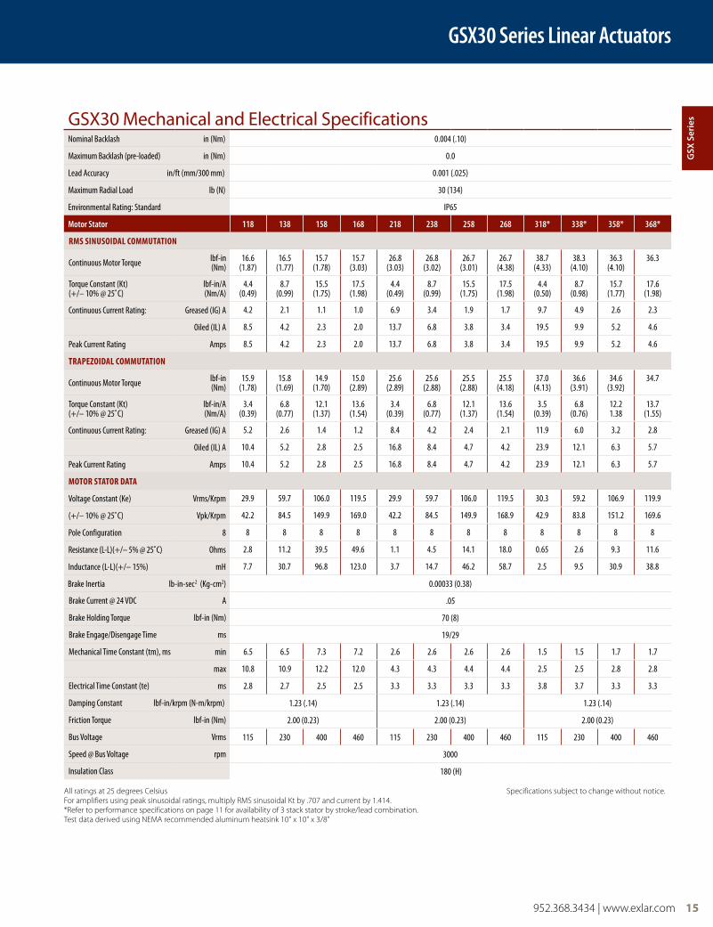
GSX30 Series Linear Actuators
GSX30 Mechanical and Electrical SpecificationsNominal Backlash in (Nm) 0.004 (.10)
Maximum Backlash (pre-loaded) in (Nm) 0.0
Lead Accuracy in/ft (mm/300 mm) 0.001 (.025)
Maximum Radial Load lb (N) 30 (134)
Environmental Rating: Standard IP65
Motor Stator 118 138 158 168 218 238 258 268 318* 338* 358* 368*
RMS SinuSoidal CoMMutation
Continuous Motor Torque lbf-in(Nm)
16.6 (1.87)
16.5 (1.77)
15.7 (1.78)
15.7 (3.03)
26.8 (3.03)
26.8 (3.02)
26.7 (3.01)
26.7 (4.38)
38.7 (4.33)
38.3 (4.10)
36.3 (4.10)
36.3
Torque Constant (Kt)(+/– 10% @ 25˚C)
lbf-in/A(Nm/A)
4.4(0.49)
8.7(0.99)
15.5(1.75)
17.5(1.98)
4.4(0.49)
8.7(0.99)
15.5(1.75)
17.5(1.98)
4.4(0.50)
8.7(0.98)
15.7(1.77)
17.6(1.98)
Continuous Current Rating: Greased (IG) A 4.2 2.1 1.1 1.0 6.9 3.4 1.9 1.7 9.7 4.9 2.6 2.3
Oiled (IL) A 8.5 4.2 2.3 2.0 13.7 6.8 3.8 3.4 19.5 9.9 5.2 4.6
Peak Current Rating Amps 8.5 4.2 2.3 2.0 13.7 6.8 3.8 3.4 19.5 9.9 5.2 4.6
tRapezoidal CoMMutation
Continuous Motor Torque lbf-in(Nm)
15.9 (1.78)
15.8 (1.69)
14.9 (1.70)
15.0 (2.89)
25.6 (2.89)
25.6 (2.88)
25.5 (2.88)
25.5 (4.18)
37.0 (4.13)
36.6 (3.91)
34.6 (3.92)
34.7
Torque Constant (Kt)(+/– 10% @ 25˚C)
lbf-in/A(Nm/A)
3.4(0.39)
6.8(0.77)
12.1(1.37)
13.6(1.54)
3.4(0.39)
6.8(0.77)
12.1(1.37)
13.6(1.54)
3.5(0.39)
6.8(0.76)
12.21.38
13.7(1.55)
Continuous Current Rating: Greased (IG) A 5.2 2.6 1.4 1.2 8.4 4.2 2.4 2.1 11.9 6.0 3.2 2.8
Oiled (IL) A 10.4 5.2 2.8 2.5 16.8 8.4 4.7 4.2 23.9 12.1 6.3 5.7
Peak Current Rating Amps 10.4 5.2 2.8 2.5 16.8 8.4 4.7 4.2 23.9 12.1 6.3 5.7
MotoR StatoR data
Voltage Constant (Ke) Vrms/Krpm 29.9 59.7 106.0 119.5 29.9 59.7 106.0 119.5 30.3 59.2 106.9 119.9
(+/– 10% @ 25˚C) Vpk/Krpm 42.2 84.5 149.9 169.0 42.2 84.5 149.9 168.9 42.9 83.8 151.2 169.6
Pole Configuration 8 8 8 8 8 8 8 8 8 8 8 8 8
Resistance (L-L)(+/– 5% @ 25˚C) Ohms 2.8 11.2 39.5 49.6 1.1 4.5 14.1 18.0 0.65 2.6 9.3 11.6
Inductance (L-L)(+/– 15%) mH 7.7 30.7 96.8 123.0 3.7 14.7 46.2 58.7 2.5 9.5 30.9 38.8
Brake Inertia lb-in-sec2 (Kg-cm2) 0.00033 (0.38)
Brake Current @ 24 VDC A .05
Brake Holding Torque lbf-in (Nm) 70 (8)
Brake Engage/Disengage Time ms 19/29
Mechanical Time Constant (tm), ms min 6.5 6.5 7.3 7.2 2.6 2.6 2.6 2.6 1.5 1.5 1.7 1.7
max 10.8 10.9 12.2 12.0 4.3 4.3 4.4 4.4 2.5 2.5 2.8 2.8
Electrical Time Constant (te) ms 2.8 2.7 2.5 2.5 3.3 3.3 3.3 3.3 3.8 3.7 3.3 3.3
Damping Constant lbf-in/krpm (N-m/krpm) 1.23 (.14) 1.23 (.14) 1.23 (.14)
Friction Torque lbf-in (Nm) 2.00 (0.23) 2.00 (0.23) 2.00 (0.23)
Bus Voltage Vrms 115 230 400 460 115 230 400 460 115 230 400 460
Speed @ Bus Voltage rpm 3000
Insulation Class 180 (H)
All ratings at 25 degrees Celsius Specifications subject to change without notice.For amplifiers using peak sinusoidal ratings, multiply RMS sinusoidal Kt by .707 and current by 1.414.*Refer to performance specifications on page 11 for availability of 3 stack stator by stroke/lead combination.Test data derived using NEMA recommended aluminum heatsink 10" x 10" x 3/8"
gSX
Ser
ies
16 952.368.3434 | www.exlar.com
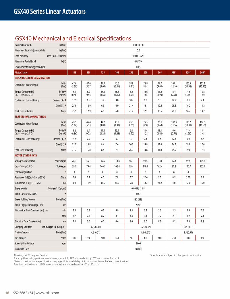
GSX40 Series Linear Actuators
GSX40 Mechanical and Electrical SpecificationsNominal Backlash in (Nm) 0.004 (.10)
Maximum Backlash (pre-loaded) in (Nm) 0.0
Lead Accuracy in/ft (mm/300 mm) 0.001 (.025)
Maximum Radial Load lb (N) 40 (179)
Environmental Rating: Standard IP65
Motor Stator 118 138 158 168 238 258 268 338* 358* 368*
RMS SinuSoidal CoMMutation
Continuous Motor Torque lbf-in(Nm)
47.6 (5.38)
47.6 (5.37)
44.7 (5.05)
45.5 (5.14)
78.8 (8.91)
78.8 (8.91)
79.7 (9.00)
107.1(12.10)
105.5(11.92)
107.1 (12.10)
Torque Constant (Kt)(+/– 10% @ 25˚C)
lbf-in/A(Nm/A)
4.1(0.46)
8.2(0.93)
14.6(1.65)
16.8(1.90)
8.2(0.93)
14.6(1.65)
16.8(1.90)
8.4(0.95)
14.6(1.65)
16.8 (1.90)
Continuous Current Rating: Greased (IG) A 12.9 6.5 3.4 3.0 10.7 6.0 5.3 14.2 8.1 7.1
Oiled (IL) A 25.9 12.9 6.9 6.0 21.4 12.1 10.6 28.5 16.2 14.2
Peak Current Rating Amps 25.9 12.9 6.9 6.0 21.4 12.1 10.6 28.5 16.2 14.2
tRapezoidal CoMMutation
Continuous Motor Torque lbf-in (Nm)
45.5 (5.14)
45.4 (5.13)
42.7 (4.83)
43.5 (4.91)
75.3 (8.51)
75.3 (8.50)
76.1 (8.60)
102.3 (11.56)
100.7 (11.38)
102.3 (11.56)
Torque Constant (Kt)(+/– 10% @ 25˚C)
lbf-in/A (Nm/A)
3.2(0.36)
6.4(0.72)
11.4(1.28)
13.1(1.48)
6.4(0.72)
11.4(1.28)
13.1(1.48)
6.6(0.74)
11.4(1.28)
13.1(1.48)
Continuous Current Rating: Greased (IG) A 15.9 7.9 4.2 3.7 13.1 7.4 6.5 17.4 9.9 8.7
Oiled (IL) A 31.7 15.8 8.4 7.4 26.3 14.8 13.0 34.9 19.8 17.4
Peak Current Rating Amps 31.7 15.8 8.4 7.4 26.3 14.8 13.0 34.9 19.8 17.4
MotoR StatoR data
Voltage Constant (Ke) Vrms/Krpm 28.1 56.1 99.5 114.8 56.1 99.5 114.8 57.4 99.5 114.8
(+/– 10% @ 25˚C) Vpk/Krpm 39.7 79.4 140.7 162.4 79.4 140.7 162.4 81.2 140.7 162.4
Pole Configuration 8 8 8 8 8 8 8 8 8 8
Resistance (L-L)(+/– 5% @ 25˚C) Ohms 0.4 1.7 6.0 7.8 0.7 2.26 3.0 0.5 1.52 1.9
Inductance (L-L)(+/– 15%) mH 3.0 11.9 37.5 49.9 5.8 18.2 24.2 4.0 12.0 16.0
Brake Inertia lb-in-sec2 (Kg-cm2) 0.00096 (1.08)
Brake Current @ 24 VDC A 0.67
Brake Holding Torque lbf-in (Nm) 97 (11)
Brake Engage/Disengage Time ms 20/29
Mechanical Time Constant (tm), ms min 5.3 5.3 6.0 5.8 2.3 2.3 2.2 1.5 1.5 1.5
max 7.7 7.7 8.7 8.4 3.3 3.3 3.2 2.1 2.2 2.1
Electrical Time Constant (te) ms 7.0 7.0 6.2 6.4 8.0 8.0 8.2 8.2 7.9 8.2
Damping Constant lbf-in/krpm (N-m/krpm) 3.25 (0.37) 3.25 (0.37) 3.25 (0.37)
Friction Torque lbf-in (Nm) 4.5 (0.51) 4.5 (0.51) 4.5 (0.51)
Bus Voltage Vrms 115 230 400 460 230 400 460 230 400 460
Speed @ Bus Voltage rpm 3000
Insulation Class 180 (H)
All ratings at 25 degrees Celsius Specifications subject to change without notice.For amplifiers using peak sinusoidal ratings, multiply RMS sinusoidal Kt by .707 and current by 1.414.*Refer to performance specifications on page 12 for availability of 3 stack stator by stroke/lead combination.Test data derived using NEMA recommended aluminum heatsink 12" x 12" x 1/2"
952.368.3434 | www.exlar.com 17
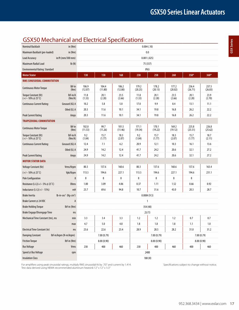
GSX50 Mechanical and Electrical SpecificationsNominal Backlash in (Nm) 0.004 (.10)
Maximum Backlash (pre-loaded) in (Nm) 0.0
Lead Accuracy in/ft (mm/300 mm) 0.001 (.025)
Maximum Radial Load lb (N) 75 (337)
Environmental Rating: Standard IP65
Motor Stator 138 158 168 238 258 268 358* 368*
RMS SinuSoidal CoMMutation
Continuous Motor Torque lbf-in (Nm)
106.9 (12.07)
104.4 (11.80)
106.2(12.00)
179.2 (20.25)
178.2 (20.13)
177.2 (20.02)
236.4 (26.71)
237.5(26.83)
Torque Constant (Kt)(+/– 10% @ 25˚C)
lbf-in/A (Nm/A)
11.8(1.33)
20.1(2.28)
23.5(2.66)
11.8(1.33)
20.1(2.28)
23.5(2.66)
20.1(2.28)
23.9(2.70)
Continuous Current Rating: Greased (IG) A 10.2 5.8 5.0 17.0 9.9 8.4 13.1 11.1
Oiled (IL) A 20.3 11.6 10.1 34.1 19.8 16.8 26.2 22.2
Peak Current Rating Amps 20.3 11.6 10.1 34.1 19.8 16.8 26.2 22.2
tRapezoidal CoMMutation
Continuous Motor Torque lbf-in (Nm)
102.0 (11.53)
99.7 (11.26)
101.5 (11.46)
171.1 (19.34)
170.1 (19.22)
169.2 (19.12)
225.8 (25.51)
226.8(25.62)
Torque Constant (Kt)(+/– 10% @ 25˚C)
lbf-in/A (Nm/A)
9.2(1.04)
15.7(1.77)
18.3(2.07)
9.2(1.04)
15.7(1.77)
18.3(2.07)
15.7(1.77)
18.7(2.11)
Continuous Current Rating: Greased (IG) A 12.4 7.1 6.2 20.9 12.1 10.3 16.1 13.6
Oiled (IL) A 24.9 14.2 12.4 41.7 24.2 20.6 32.1 27.2
Peak Current Rating Amps 24.9 14.2 12.4 41.7 24.2 20.6 32.1 27.2
MotoR StatoR data
Voltage Constant (Ke) Vrms/Krpm 80.3 137.6 160.6 80.3 137.6 160.6 137.6 163.4
(+/– 10% @ 25˚C) Vpk/Krpm 113.5 194.6 227.1 113.5 194.6 227.1 194.6 231.1
Pole Configuration 8 8 8 8 8 8 8 8
Resistance (L-L)(+/– 5% @ 25˚C) Ohms 1.00 3.09 4.06 0.37 1.11 1.52 0.66 0.92
Inductance (L-L)(+/– 15%) mH 23.7 69.6 94.8 10.7 31.6 43.0 20.3 28.7
Brake Inertia lb-in-sec2 (Kg-cm2) 0.0084 (9.5)
Brake Current @ 24 VDC A 1
Brake Holding Torque lbf-in (Nm) 354 (40)
Brake Engage/Disengage Time ms 25/73
Mechanical Time Constant (tm), ms min 3.3 3.4 3.3 1.2 1.2 1.2 0.7 0.7
max 4.7 5.0 4.8 1.8 1.8 1.8 1.1 1.0
Electrical Time Constant (te) ms 23.6 22.6 23.4 28.9 28.5 28.2 31.0 31.2
Damping Constant lbf-in/krpm (N-m/krpm) 7.00 (0.79) 7.00 (0.79) 7.00 (0.79)
Friction Torque lbf-in (Nm) 8.00 (0.90) 8.00 (0.90) 8.00 (0.90)
Bus Voltage Vrms 230 400 460 230 400 460 400 460
Speed @ Bus Voltage rpm 2400
Insulation Class 180 (H)
For amplifiers using peak sinusoidal ratings, multiply RMS sinusoidal Kt by .707 and current by 1.414. Specifications subject to change without notice.Test data derived using NEMA recommended aluminum heatsink 12" x 12" x 1/2"
GSX50 Series Linear Actuators
gSX
Ser
ies
18 952.368.3434 | www.exlar.com
GSX60 Series Linear Actuators
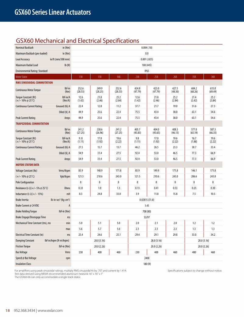
GSX60 Mechanical and Electrical SpecificationsNominal Backlash in (Nm) 0.004 (.10)
Maximum Backlash (pre-loaded) in (Nm) 0.0
Lead Accuracy in/ft (mm/300 mm) 0.001 (.025)
Maximum Radial Load lb (N) 100 (445)
Environmental Rating: Standard IP65
Motor Stator 138 158 168 238 258 268 358 368
RMS SinuSoidal CoMMutation
Continuous Motor Torque lbf-in (Nm)
252.6(28.53)
249.9 (28.23)
252.6(28.53)
424.8 (47.79)
423.0 (47.79)
427.5 (48.30)
604.2 (68.26)
615.0 (69.49)
Torque Constant (Kt)(+/– 10% @ 25˚C)
lbf-in/A (Nm/A)
12.6(1.42)
21.8(2.46)
25.2(2.84)
12.6(1.42)
21.8(2.46)
25.2(2.84)
21.4(2.42)
25.2(2.84)
Continuous Current Rating: Greased (IG) A 22.4 12.8 11.2 37.7 21.7 19.0 31.6 27.3
Oiled (IL) A 44.9 25.6 22.4 75.5 43.4 38.0 63.1 54.6
Peak Current Rating Amps 44.9 25.6 22.4 75.5 43.4 38.0 63.1 54.6
tRapezoidal CoMMutation
Continuous Motor Torque lbf-in (Nm)
241.2 (27.25)
238.6(26.96)
241.2 (27.25)
405.7 (45.83)
404.0 (45.65)
408.3(46.13)
577.0(65.19)
587.3(66.35)
Torque Constant (Kt)(+/– 10% @ 25˚C)
lbf-in/A (Nm/A)
9. 8(1.11)
17.0(1.92)
19.6(2.22)
9.8(1.11)
17.0(1.92)
19.6(2.22)
16.7(1.88)
19.6(2.22)
Continuous Current Rating: Greased (IG) A 27.5 15.7 13.7 46.2 26.5 23.3 38.7 33.4
Oiled (IL) A 54.9 31.4 27.5 92.4 53.0 46.5 77.3 66.9
Peak Current Rating Amps 54.9 31.4 27.5 92.4 53.0 46.5 77.3 66.9
MotoR StatoR data
Voltage Constant (Ke) Vrms/Krpm 85.9 148.9 171.8 85.9 149.9 171.8 146.1 171.8
(+/– 10% @ 25˚C) Vpk/Krpm 121.5 210.6 243.0 121.5 210.6 243.0 206.6 243.0
Pole Configuration 8 8 8 8 8 8 8 8
Resistance (L-L)(+/– 5% @ 25˚C) Ohms 0.33 1.0 1.3 0.13 0.41 0.53 0.23 0.30
Inductance (L-L)(+/– 15%) mH 8.3 24.8 33.0 3.9 11.8 15.8 7.5 10.3
Brake Inertia lb-in-sec2 (Kg-cm2) 0.02815 (31.8)
Brake Current @ 24 VDC A 1.45
Brake Holding Torque lbf-in (Nm) 708 (80)
Brake Engage/Disengage Time ms 53/97
Mechanical Time Constant (tm), ms min 5.0 5.1 5.0 2.0 2.1 2.0 1.2 1.2
max 5.6 5.7 5.6 2.3 2.3 2.3 1.3 1.3
Electrical Time Constant (te) ms 25.4 24.6 25.1 29.4 29.1 29.8 33.0 34.2
Damping Constant lbf-in/krpm (N-m/krpm) 28.0 (3.16) 28.0 (3.16) 28.0 (3.16)
Friction Torque lbf-in (Nm) 20.0 (2.26) 20.0 (2.26) 20.0 (2.26)
Bus Voltage Vrms 230 400 460 230 400 460 400 460
Speed @ Bus Voltage rpm 2400
Insulation Class 180 (H)
For amplifiers using peak sinusoidal ratings, multiply RMS sinusoidal Kt by .707 and current by 1.414. Specifications subject to change without notice.Test data derived using NEMA recommended aluminum heatsink 16" x 16" x 1"The GSX60-06 can only accommodate a single stack stator.
952.368.3434 | www.exlar.com 19
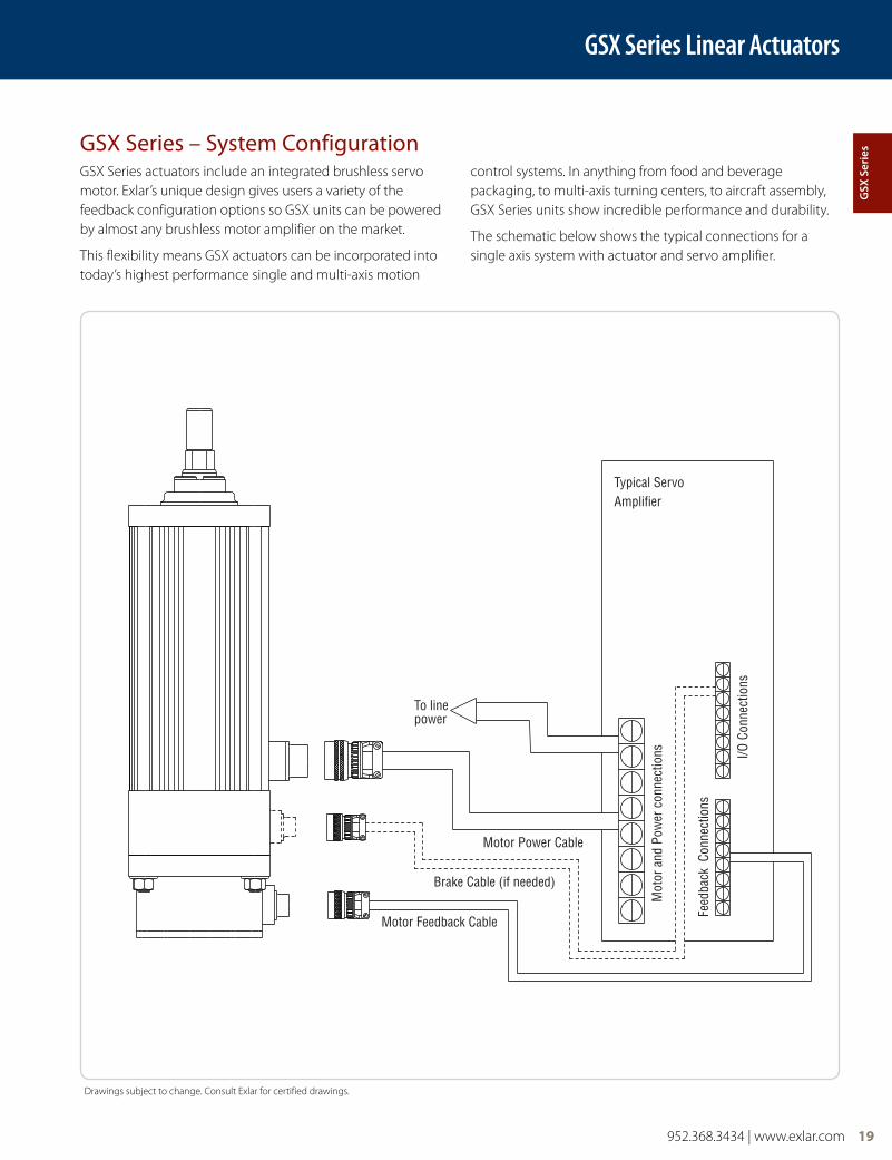
GSX Series actuators include an integrated brushless servo motor. Exlar’s unique design gives users a variety of the feedback configuration options so GSX units can be powered by almost any brushless motor amplifier on the market.
This flexibility means GSX actuators can be incorporated into today’s highest performance single and multi-axis motion
control systems. In anything from food and beverage packaging, to multi-axis turning centers, to aircraft assembly, GSX Series units show incredible performance and durability.
The schematic below shows the typical connections for a single axis system with actuator and servo amplifier.
GSX Series – System Configuration
GSX Series Linear Actuators
Drawings subject to change. Consult Exlar for certified drawings.
Brake Cable (if needed)
Motor Power Cable
Motor Feedback Cable
To linepower
Typical ServoAmplifier
Mot
or a
nd P
ower
con
nect
ions
Feed
back
Con
nect
ions
I/O C
onne
ctio
ns
gSX
Ser
ies
20 952.368.3434 | www.exlar.com
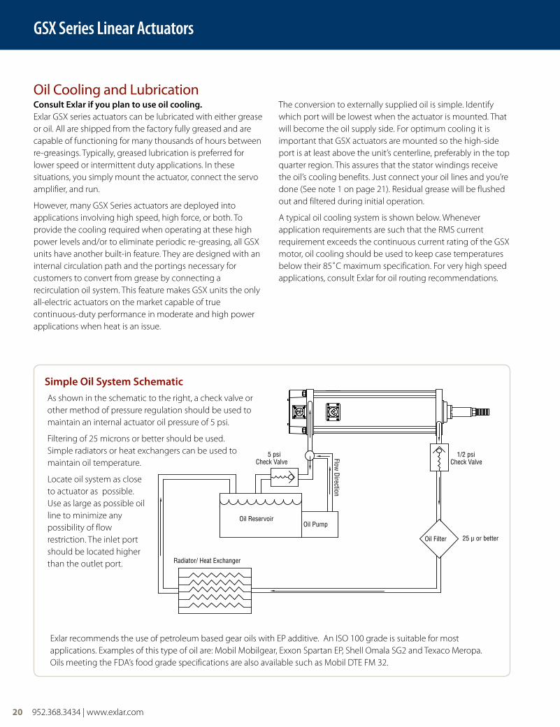
consult exlar if you plan to use oil cooling.Exlar GSX series actuators can be lubricated with either grease or oil. All are shipped from the factory fully greased and are capable of functioning for many thousands of hours between re-greasings. Typically, greased lubrication is preferred for lower speed or intermittent duty applications. In these situations, you simply mount the actuator, connect the servo amplifier, and run.
However, many GSX Series actuators are deployed into applications involving high speed, high force, or both. To provide the cooling required when operating at these high power levels and/or to eliminate periodic re-greasing, all GSX units have another built-in feature. They are designed with an internal circulation path and the portings necessary for customers to convert from grease by connecting a recirculation oil system. This feature makes GSX units the only all-electric actuators on the market capable of true continuous-duty performance in moderate and high power applications when heat is an issue.
The conversion to externally supplied oil is simple. Identify which port will be lowest when the actuator is mounted. That will become the oil supply side. For optimum cooling it is important that GSX actuators are mounted so the high-side port is at least above the unit’s centerline, preferably in the top quarter region. This assures that the stator windings receive the oil’s cooling benefits. Just connect your oil lines and you’re done (See note 1 on page 21). Residual grease will be flushed out and filtered during initial operation.
A typical oil cooling system is shown below. Whenever application requirements are such that the RMS current requirement exceeds the continuous current rating of the GSX motor, oil cooling should be used to keep case temperatures below their 85˚C maximum specification. For very high speed applications, consult Exlar for oil routing recommendations.
Oil Cooling and Lubrication
Radiator/ Heat Exchanger
Oil Filter 25 µ or better
Check Valve
Oil Reservoir
5 psi 1/2 psiCheck Valve
Oil Pump
Flow Direction
As shown in the schematic to the right, a check valve or other method of pressure regulation should be used to maintain an internal actuator oil pressure of 5 psi.
Filtering of 25 microns or better should be used. Simple radiators or heat exchangers can be used to maintain oil temperature.
Locate oil system as close to actuator as possible. Use as large as possible oil line to minimize any possibility of flow restriction. The inlet port should be located higher than the outlet port.
Simple oil System Schematic
Exlar recommends the use of petroleum based gear oils with EP additive. An ISO 100 grade is suitable for most applications. Examples of this type of oil are: Mobil Mobilgear, Exxon Spartan EP, Shell Omala SG2 and Texaco Meropa. Oils meeting the FDA’s food grade specifications are also available such as Mobil DTE FM 32.
GSX Series Linear Actuators
952.368.3434 | www.exlar.com 21
use this relationship to determine oil flow requirements: w
consider The Following example:
GSX Series Linear Actuators
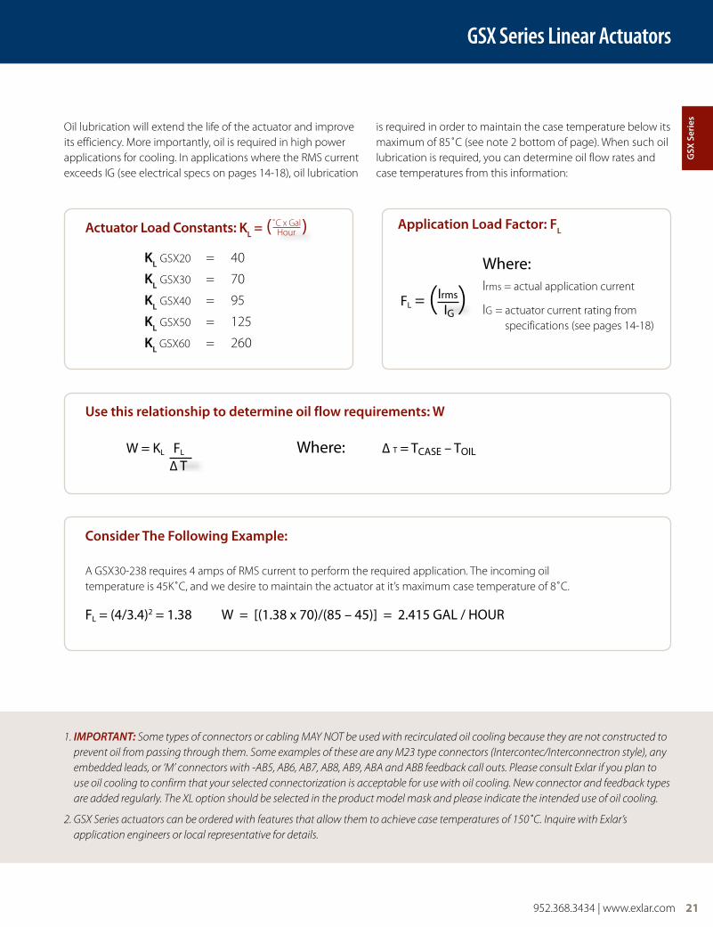
Oil lubrication will extend the life of the actuator and improve its efficiency. More importantly, oil is required in high power applications for cooling. In applications where the RMS current exceeds IG (see electrical specs on pages 14-18), oil lubrication
is required in order to maintain the case temperature below its maximum of 85˚C (see note 2 bottom of page). When such oil lubrication is required, you can determine oil flow rates and case temperatures from this information:
1. IMPORTANT: Some types of connectors or cabling MAY NOT be used with recirculated oil cooling because they are not constructed to prevent oil from passing through them. Some examples of these are any M23 type connectors (Intercontec/Interconnectron style), any embedded leads, or ‘M’ connectors with -AB5, AB6, AB7, AB8, AB9, ABA and ABB feedback call outs. Please consult Exlar if you plan to use oil cooling to confirm that your selected connectorization is acceptable for use with oil cooling. New connector and feedback types are added regularly. The XL option should be selected in the product model mask and please indicate the intended use of oil cooling.
2. GSX Series actuators can be ordered with features that allow them to achieve case temperatures of 150˚C. Inquire with Exlar’s application engineers or local representative for details.
application load Factor: Fl
Where:Irms = actual application current
IG = actuator current rating from specifications (see pages 14-18)
W = KL FL Where: ∆ T = TCASE – TOIL ∆ T
A GSX30-238 requires 4 amps of RMS current to perform the required application. The incoming oil temperature is 45K˚C, and we desire to maintain the actuator at it’s maximum case temperature of 8˚C.
FL = (4/3.4)2 = 1.38 W = [(1.38 x 70)/(85 – 45)] = 2.415 GAL / HOUR
FL = (Irms) IG
actuator load constants: kl = ( )
kl GSX20 = 40
kl GSX30 = 70
kl GSX40 = 95
kl GSX50 = 125
kl GSX60 = 260
˚C x GalHour
gSX
Ser
ies
22 952.368.3434 | www.exlar.com
GSX Series Linear Actuators
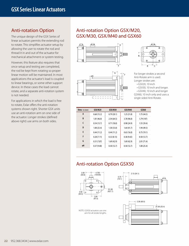
Anti-rotation OptionThe unique design of the GSX Series of linear actuators permits the extending rod to rotate. This simplifies actuator setup by allowing the user to rotate the rod and thread it in and out of the actuator for mechanical attachment or system testing.
However, this feature also requires that once setup and testing are completed, the rod be kept from rotating so proper linear motion will be maintained. In most applications the actuator’s load is coupled to linear bearings, or some other support device. In these cases the load cannot rotate, and a separate anti-rotation system is not needed.
For applications in which the load is free to rotate, Exlar offers the anti-rotation systems shown right. Shorter GSX units use an anti-rotation arm on one side of the actuator. Longer strokes (defined above right) use arms on both sides.
Anti-rotation Option GSX/M20, GSX/M30, GSX/M40 and GSX60
Anti-rotation Option GSX50
CB
A
D
E
GøH
F
4.750(120.65)
2.00(50.8)
2.50(63.5)
3.84(97.5)
R1.09(R27.7)
2.13 (54.1)
0.75(19.1)
2.38 (60.5)
ø1.00 (25.4)
For longer strokes a second Anti-Rotate arm is used. Longer strokes are: • GSX20, 10 inch • GSX30, 10 inch and longer. • GSX40, 10 inch and longerGSX60, 10 inch only and uses a single sided Anti-Rotate.
Dims- in (mm) GSX/M20 GSX/M30 GSX/M40 GSX60
A 0.60 (15.2) 0.79 (20.1) 1.25 (31.8) 1.75 (44.5)
B 1.81 (46.0) 2.54 (64.5) 3.78 (96.0) 5.79 (147)
C 0.54 (13.7) 0.71 (18.0) 0.98 (24.9) 1.55 (39.4)
D 1.00 (25.4) 1.30 (33.0) 1.64 (41.7) 1.94 (49.3)
E 0.44 (11.2) 0.44 (11.2) 0.63 (16.0) 0.75 (19.1)
F 0.28 (7.11) 0.32 (8.13) 0.38 (9.65) 0.50 (12.7)
G 0.31 (7.87) 1.69 (42.9) 1.69 (42.9) 2.81 (71.4)
øH 0.37 (9.40) 0.50 (12.7) 0.50 (12.7) 1.00 (25.4)
NOTE: GSX50 actuators use one arm for all stroke lengths.
952.368.3434 | www.exlar.com 23
GSX Series Linear Actuators
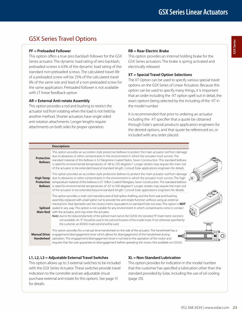
PF = Preloaded Follower This option offers a true zero backlash follower for the GSX Series actuator. The dynamic load rating of zero backlash, preloaded screws is 63% of the dynamic load rating of the standard non-preloaded screws. The calculated travel life of a preloaded screw will be 25% of the calculated travel life of the same size and lead of a non-preloaded screw for the same application. Preloaded follower is not available with LT linear feedback option.
aR = external anti-rotate assembly This option provides a rod and bushing to restrict the actuator rod from rotating when the load is not held by another method. Shorter actuators have single sided anti-rotation attachments. Longer lengths require attachments on both sides for proper operation.
Rb = Rear electric brake This option provides an internal holding brake for the GSX Series actuators. The brake is spring activated and electrically released.
XT = Special Travel option Selections The XT Option can be used to specify various special travel options on the GSX Series of Linear Actuators. Because this option can be used to specify many things, it is important that an order including the -XT option spell out in detail, the exact options being selected by the including of the -XT in the model number.
It is recommended that prior to ordering an actuator including the -XT specifier that a quote be obtained through Exlar’s special products application engineers for the desired options, and that quote be referenced on, or included with any order placed.
l1, l2, l3 = adjustable external Travel Switches This option allows up to 3 external switches to be included with the GSX Series Actuator. These switches provide travel indication to the controller and are adjustable (must purchase external anti-rotate for this option). See page 31 for details.
Xl = non-Standard lubrication This option provides for indication in the model number that the customer has specified a lubrication other than the standard provided by Exlar, including the use of oil cooling (page 20).
GSX Series Travel Options
descriptions
Protective bellows
This option provides an accordion style protective bellows to protect the main actuator rod from damage due to abrasives or other contaminants in the environment in which the actuator must survive. The standard material of this bellows is S2 Neoprene Coated Nylon, Sewn Construction. This standard bellows is rated for environmental temperatures of -40 to 250 degrees F. Longer strokes may require the main rod of the actuator to be extended beyond standard length. Consult Exlar applications engineers for details.
high Temp Protective
bellows
This option provides an accordion style protective bellows to protect the main actuator rod from damage due to abrasives or other contaminants in the environment in which the actuator must survive. The high temperature material of this bellows is D1 Teflon Coated Fiberglass, Sewn Construction. This standard bellows is rated for environmental temperatures of -67 to 500 degrees F. Longer strokes may require the main rod of the actuator to be extended beyond standard length. Consult Exlar applications engineers for details.
Splined Main Rod
This option provides a main rod manufactured of ball spline shafting, and the front seal and bushing assembly replaced with a ball spline nut to provide the anti-rotate function without using an external mechanism. Rod diameters are the closest metric equivalents to standard Exlar rod sizes. This option is noT sealed in any way. This option is not suitable for any environment in which contaminants come in contact with the actuator, and may enter the actuator. Note: due to the reduced diameter of the splined main rod on the GSX50, the standard “A” male metric rod end is
not available. An “X” should be used in the rod end location of the model mask. If not otherwise specified by the customer, an M24X2 male rod end will be used.
Manual drive handwheel
This option provides for a manual drive handwheel on the side of the actuator. The handwheel has a engagement/disengagement lever which allows for disengagement of the handwheel during operation. This engagement/disengagement lever is not tied to the operation of the motor and requires that the user guarantee its disengagement before operating the motor. Not available on GSX20.
gSX
Ser
ies
24 952.368.3434 | www.exlar.com
GSX Series Linear Actuators
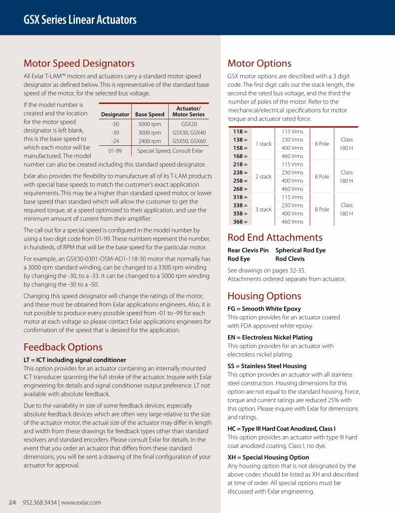
Motor OptionsGSX motor options are described with a 3 digit code. The first digit calls out the stack length, the second the rated bus voltage, and the third the number of poles of the motor. Refer to the mechanical/electrical specifications for motor torque and actuator rated force.
Rod End AttachmentsRear clevis Pin Spherical Rod eye Rod eye Rod clevis
See drawings on pages 32-35. Attachments ordered separate from actuator.
Housing OptionsFg = Smooth white epoxy This option provides for an actuator coated with FDA approved white epoxy.
en = electroless nickel Plating This option provides for an actuator with electroless nickel plating.
SS = Stainless Steel housing This option provides an actuator with all stainless steel construction. Housing dimensions for this option are not equal to the standard housing. Force, torque and current ratings are reduced 25% with this option. Please inquire with Exlar for dimensions and ratings.
hc = Type III hard coat anodized, class I This option provides an actuator with type III hard coat anodized coating. Class I, no dye.
Xh = Special housing option Any housing option that is not designated by the above codes should be listed as XH and described at time of order. All special options must be discussed with Exlar engineering.
Motor Speed DesignatorsAll Exlar T-LAM™ motors and actuators carry a standard motor speed designator as defined below. This is representative of the standard base speed of the motor, for the selected bus voltage.
If the model number is created and the location for the motor speed designator is left blank, this is the base speed to which each motor will be manufactured. The model number can also be created including this standard speed designator.
Exlar also provides the flexibility to manufacture all of its T-LAM products with special base speeds to match the customer’s exact application requirements. This may be a higher than standard speed motor, or lower base speed than standard which will allow the customer to get the required torque, at a speed optimized to their application, and use the minimum amount of current from their amplifier.
The call out for a special speed is configured in the model number by using a two digit code from 01-99. These numbers represent the number, in hundreds, of RPM that will be the base speed for the particular motor.
For example, an GSX30-0301-OSM-AD1-118-30 motor that normally has a 3000 rpm standard winding, can be changed to a 3300 rpm winding by changing the -30, to a -33. It can be changed to a 5000 rpm winding by changing the -30 to a -50.
Changing this speed designator will change the ratings of the motor, and these must be obtained from Exlar applications engineers. Also, it is not possible to produce every possible speed from -01 to -99 for each motor at each voltage so please contact Exlar applications engineers for confirmation of the speed that is desired for the application.
Feedback OptionslT = IcT including signal conditioner This option provides for an actuator containing an internally mounted ICT transducer spanning the full stroke of the actuator. Inquire with Exlar engineering for details and signal conditioner output preference. LT not available with absolute feedback.
Due to the variability in size of some feedback devices, especially absolute feedback devices which are often very large relative to the size of the actuator motor, the actual size of the actuator may differ in length and width from these drawings for feedback types other than standard resolvers and standard encoders. Please consult Exlar for details. In the event that you order an actuator that differs from these standard dimensions, you will be sent a drawing of the final configuration of your actuator for approval.
designator base Speedactuator/
Motor Series
-50
-30
-24
5000 rpm
3000 rpm
2400 rpm
GSX20
GSX30, GSX40
GSX50, GSX60
01-99 Special Speed, Consult Exlar
118 =
1 stack
115 Vrms
8 Pole Class
180 H
138 = 230 Vrms158 = 400 Vrms168 = 460 Vrms218 =
2 stack
115 Vrms
8 Pole Class
180 H
238 = 230 Vrms258 = 400 Vrms268 = 460 Vrms318 =
3 stack
115 Vrms
8 Pole Class
180 H
338 = 230 Vrms358 = 400 Vrms368 = 460 Vrms
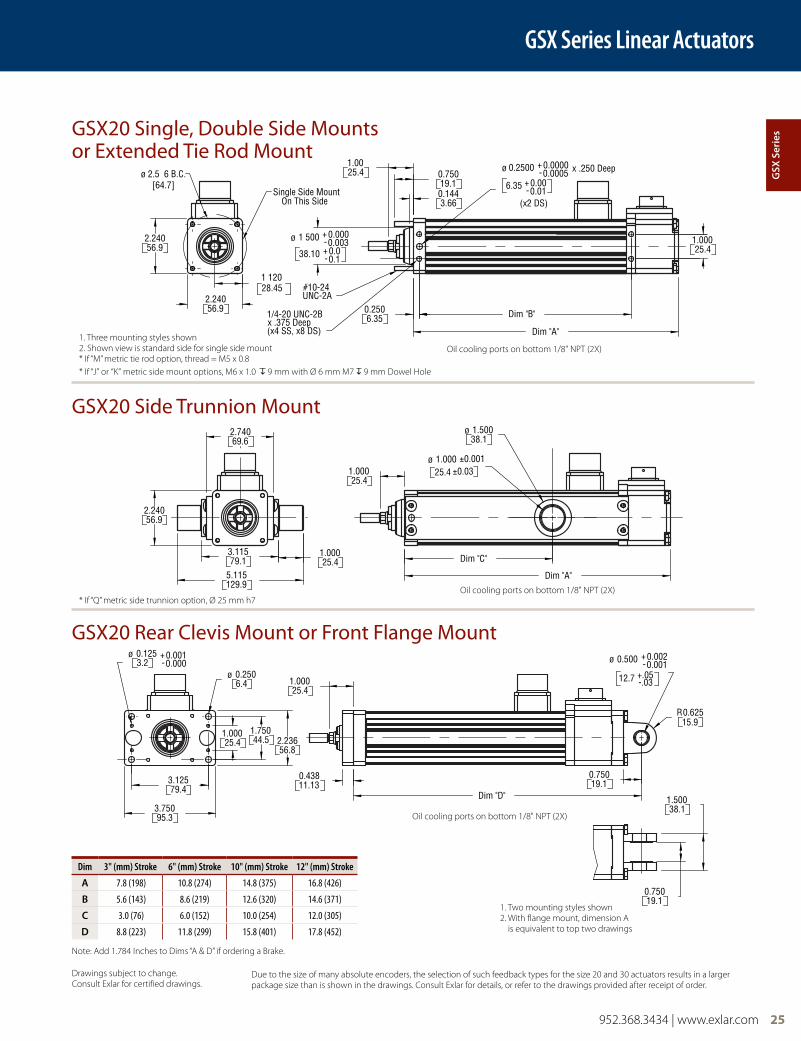
GSX20 Single, Double Side Mounts or Extended Tie Rod Mount
GSX20 Side Trunnion Mount
GSX20 Rear Clevis Mount or Front Flange Mount
952.368.3434 | www.exlar.com 25
GSX Series Linear Actuators
Drawings subject to change. Consult Exlar for certified drawings.
Due to the size of many absolute encoders, the selection of such feedback types for the size 20 and 30 actuators results in a larger package size than is shown in the drawings. Consult Exlar for details, or refer to the drawings provided after receipt of order.
1/4-20 UNC-2Bx .375 Deep(x4 SS, x8 DS)
#10-24UNC-2A
1.0003.115
5.115129.9
79.1 25.4
Dim "C"
Dim "A"
Dim "A"
1 500
38.10
Single Side MountOn This Side
ø2.240
2.24056.9
56.9
2.74069.6
2.24056.9
1 12028.45
1.00025.4
0.2506.35
±0.03±0.001
38.11.500
1.00025.4
ø
ø
Dim "B"
1.0025.4 0.750
19.10.1443.66
6.35
0.2500ø
1.00025.4
x .250 Deep0.00000.0005
+-
0.010.00
-+
0.003-0.000+
+ 0.0-0.1
(x2 DS)
ø 2.5 6 B.C.[64.7]
x .3 5 eep(x SS x8 DS
U C 2A
1.00025.4
2.236
3.12579.4
3.75095.3
0.125ø3.2
1.00025.4 44.5
1.750
56.8
.1151 9.9
0.2506.4
79
ø
0.43811.13
2 4
Dim "D"
0.75019.1
0.500
12.7
0.75019.1
ø
15.90.625
1.50038.1
R
0.0010.002+
.03+.05-
-
D
38 1
On This S de
56.9
6.9
69 6
6 9
28.45
25 4
6 35
±0 03
8 1
5 4
25 419.1
1443 66
5
25 4
0. 005
010 0
0.0030 00.1
2 DS)
64 7]
0.0000.001+
-
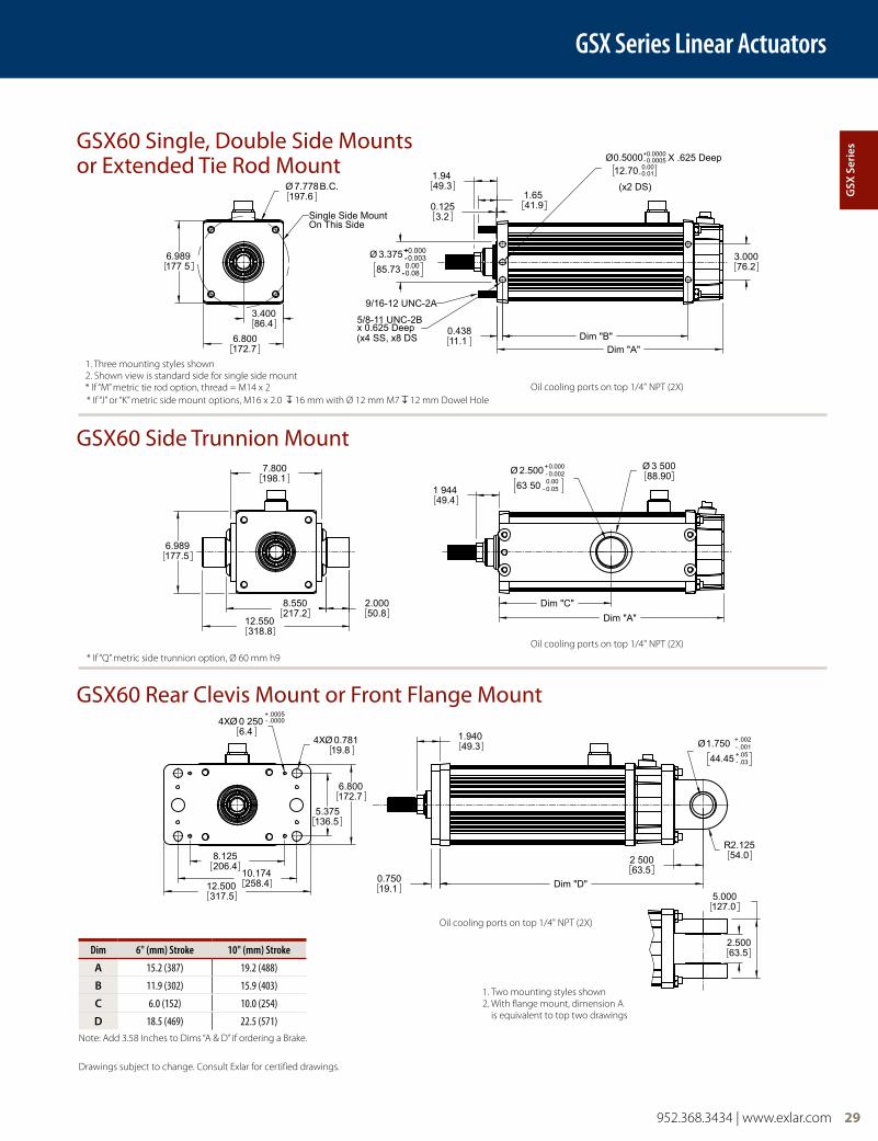
1. Three mounting styles shown2. Shown view is standard side for single side mount* If “M” metric tie rod option, thread = M5 x 0.8
Oil cooling ports on bottom 1/8" NPT (2X)
Oil cooling ports on bottom 1/8" NPT (2X)
Oil cooling ports on bottom 1/8" NPT (2X)
1. Two mounting styles shown2. With flange mount, dimension A
is equivalent to top two drawings
Dim 3" (mm) Stroke 6" (mm) Stroke 10" (mm) Stroke 12" (mm) Stroke
a 7.8 (198) 10.8 (274) 14.8 (375) 16.8 (426)
b 5.6 (143) 8.6 (219) 12.6 (320) 14.6 (371)
c 3.0 (76) 6.0 (152) 10.0 (254) 12.0 (305)
d 8.8 (223) 11.8 (299) 15.8 (401) 17.8 (452)
Note: Add 1.784 Inches to Dims “A & D” if ordering a Brake.
gSX
Ser
ies
* If “J” or “K” metric side mount options, M6 x 1.0 9 mm with Ø 6 mm M7 9 mm Dowel Hole
* If “Q” metric side trunnion option, Ø 25 mm h7
Dim "D"
1.3233.5
5.940150.9
5.250133.4
3.68893.7
Ø 0.397 (4x)10.08
3.100
MAX78.7
2.43061.72
0.2506.35
0.43811.13
0.99325.2
2.50063.5
1.25031.8
Ø 0.750 -.001+.002
19 05 -0.03+0 05
R0.75019.1
±.0005
1.3233 5
5.921150.4
1.00025 4
3.92199 6
3.100
MAX78 7
3.100
3.54690 1
Dim "C"
Dim "A"
0 750 0+.00
Ø 1.50038 1
Ø 1.000 ±0.00125 40 ±0.03
1 32
1.3233.5
0.2506.35(x4 SS, x8 DS)
1/4-20 UNC-2Bx 0.38 Deep
0.0902.29
0.96224.4
5 9 1
0003 9216
3 10078 7
3.04677.4
3.100
MAX78.7
Single Side MountOn This Side
Ø 3.536 BC89.8
3 546
1.52338.68
1/4-20UNC-2A
Ø 2.000 -0.003+0.000
50.8 -0.10.0
1.75044.5
Dim "A"
Ø 0.2500 -0.0005+0.0000
x 0.250 Deep6.35 -0.01
0.00
1 50
1 000 0
Dim "B"
(x2 DS)
26 952.368.3434 | www.exlar.com
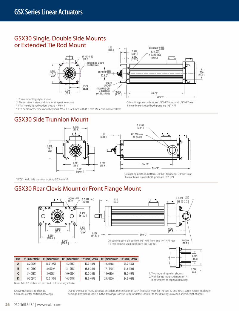
GSX Series Linear Actuators
GSX30 Single, Double Side Mounts or Extended Tie Rod Mount
GSX30 Side Trunnion Mount
GSX30 Rear Clevis Mount or Front Flange Mount
Drawings subject to change. Consult Exlar for certified drawings.
Due to the size of many absolute encoders, the selection of such feedback types for the size 20 and 30 actuators results in a larger package size than is shown in the drawings. Consult Exlar for details, or refer to the drawings provided after receipt of order.
1. Three mounting styles shown2. Shown view is standard side for single side mount* If “M” metric tie rod option, thread = M6 x 1
Oil cooling ports on bottom 1/8" NPT front and 1/4" NPT rearIf a rear brake is used both ports are 1/8" NPT
Oil cooling ports on bottom 1/8" NPT front and 1/4" NPT rearIf a rear brake is used both ports are 1/8" NPT
Oil cooling ports on bottom 1/8" NPT front and 1/4" NPT rearIf a rear brake is used both ports are 1/8" NPT
1. Two mounting styles shown2. With flange mount, dimension A
is equivalent to top two drawings
Dim 3" (mm) Stroke 6" (mm) Stroke 10" (mm) Stroke 12" (mm) Stroke 14" (mm) Stroke 18" (mm) Stroke
a 8.2 (209) 10.7 (272) 15.2 (387) 17.2 (437) 19.2 (488) 23.2 (590)
b 6.1 (156) 8.6 (219) 13.1 (333) 15.1 (384) 17.1 (435) 21.1 (536)
c 5.4 (137) 8.0 (203) 10.0 (254) 12.0 (305) 14.0 (356) 18.0 (457)
d 9.5 (241) 12.0 (304) 16.5 (418) 18.5 (469) 20.5 (520) 24.5 (621)Note: Add 1.6 Inches to Dims “A & D” if ordering a Brake.
* If “J” or “K” metric side mount options, M6 x 1.0 9 mm with Ø 6 mm M7 9 mm Dowel Hole
* If “Q” metric side trunnion option, Ø 25 mm h7
124.46.898175.2
Dim "A"
4.400
4.898
111.8
3.90099.1
1.00025.4
50 838.10±0.03
1.65041.9
Dim "C"
1.500Ø ±0.001 2 000Ø
(4X)
96.53.800
13.1(4X)
0.516
195.17.680
5.250
172.76.800
133.4 Ø
74.22.920
0.250Ø6.4
15.90.625
Dim "D"
1.6541.9
31.81.250
19.1R
2.50063.5
0.750
.002+
19 05
0.750Ø
.03-
.05
.001-
31.81.250
(107.8) B.C.
Single Side Mount
99.13.900
3.90099.1
On This Side
Ø 4.243
7.90.313
Dim "B"
63.52.499
41.91.65
2.5
1.38035.1
0.100
44.51.750
-9.530.0005-
0.000.01
3/8-16 UNC-2A
3/8 -16 UNC-2BDim "A"
(x4 SS, x8 DS)x 0.75 Deep
0.3750Ø 0.0000+
(x2 DS)
x .438 Deep
±.001
952.368.3434 | www.exlar.com 27
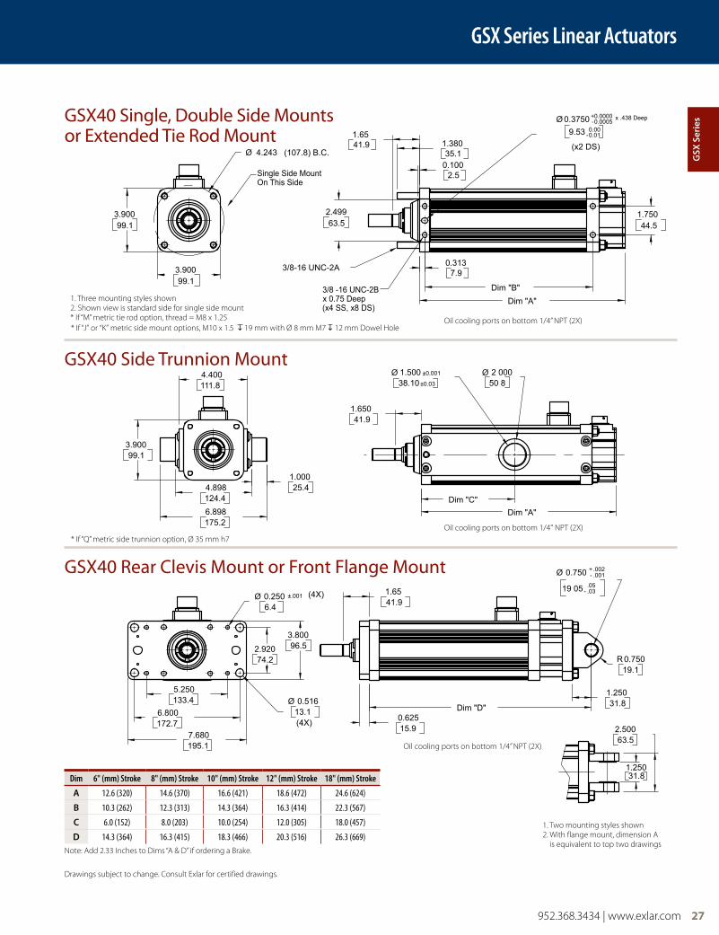
GSX Series Linear Actuators
Drawings subject to change. Consult Exlar for certified drawings.
Oil cooling ports on bottom 1/4” NPT (2X)
Oil cooling ports on bottom 1/4" NPT (2X)
Oil cooling ports on bottom 1/4” NPT (2X)
Dim 6" (mm) Stroke 8" (mm) Stroke 10" (mm) Stroke 12" (mm) Stroke 18" (mm) Stroke
a 12.6 (320) 14.6 (370) 16.6 (421) 18.6 (472) 24.6 (624)
b 10.3 (262) 12.3 (313) 14.3 (364) 16.3 (414) 22.3 (567)
c 6.0 (152) 8.0 (203) 10.0 (254) 12.0 (305) 18.0 (457)
d 14.3 (364) 16.3 (415) 18.3 (466) 20.3 (516) 26.3 (669)Note: Add 2.33 Inches to Dims “A & D” if ordering a Brake.
GSX40 Single, Double Side Mounts or Extended Tie Rod Mount
GSX40 Side Trunnion Mount
GSX40 Rear Clevis Mount or Front Flange Mount
1. Two mounting styles shown2. With flange mount, dimension A
is equivalent to top two drawings
1. Three mounting styles shown2. Shown view is standard side for single side mount* If “M” metric tie rod option, thread = M8 x 1.25
gSX
Ser
ies
* If “J” or “K” metric side mount options, M10 x 1.5 19 mm with Ø 8 mm M7 12 mm Dowel Hole
* If “Q” metric side trunnion option, Ø 35 mm h7
28 952.368.3434 | www.exlar.com
GSX Series Linear Actuators
1/2-13 UNC-2Bx .750 Deep
(x4 SS, x8 DS)
3.00076.2
Dim "B"0.40610.3
Dim "A"
1.50038.1
2.12554.0
0.1253.2
3.000 -0.003+0.000
76.2 -0.10.0
Ø 0.5000 -0.0005+0.0000
x 0.500 Deep12.7 -0.0
0.0
1/2-13 UNC-2A
Ø 6.125 B.C.155.6
5.500139.7
Single Side MountOn This Side
Dim "C"
Dim "A"
2.12554.0
Ø 2.000±0.00150.8±0.0
Ø 2.50063.56.250
158.8
5.500139.7
7.000177.8
1.50038.1
10.000254.0
2.12554.0
0.75019.1 Dim "D"
Ø 1.000 -.001+.002
25.40 -.03+.05
R1.00025.4
Ø 0.250
(4x)6.4 Ø 0.563
(4x)14.3
7.625
(4x)193.7
9.500241.3
4.875
(2x)123.8
3.250
(2x)82.6
6.500
(2x)165.1
1.50038.1
3.00076.2
5.500 [139.7]
2.750 [69.9]
(x2 DS)
-.0000+.0005
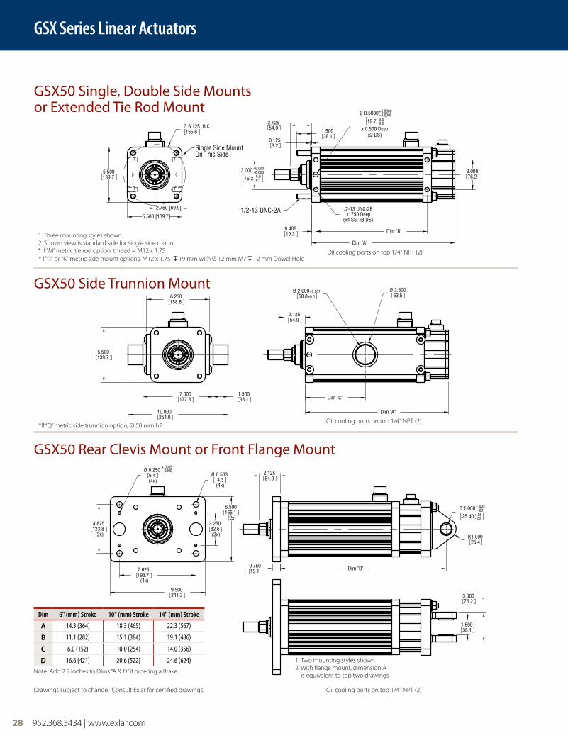
GSX50 Single, Double Side Mounts or Extended Tie Rod Mount
GSX50 Side Trunnion Mount
GSX50 Rear Clevis Mount or Front Flange Mount
Drawings subject to change. Consult Exlar for certified drawings.
1. Three mounting styles shown2. Shown view is standard side for single side mount* If “M” metric tie rod option, thread = M12 x 1.75
1. Two mounting styles shown2. With flange mount, dimension A
is equivalent to top two drawings
Dim 6" (mm) Stroke 10" (mm) Stroke 14" (mm) Stroke
a 14.3 (364) 18.3 (465) 22.3 (567)
b 11.1 (282) 15.1 (384) 19.1 (486)
c 6.0 (152) 10.0 (254) 14.0 (356)
d 16.6 (421) 20.6 (522) 24.6 (624)Note: Add 2.5 Inches to Dims “A & D” if ordering a Brake.
Oil cooling ports on top 1/4" NPT (2)
Oil cooling ports on top 1/4" NPT (2)
Oil cooling ports on top 1/4" NPT (2)
* If “J” or “K” metric side mount options, M12 x 1.75 19 mm with Ø 12 mm M7 12 mm Dowel Hole
* If “Q” metric side trunnion option, Ø 50 mm h7
952.368.3434 | www.exlar.com 29
GSX Series Linear Actuators
49.31.94
3.20.125
12.550
317.512.500
206.48.125
4XØ
172.76.800
19.80.781
258.410.174
136.55.375
217.28.550
6.40 250
318.8
4XØ
19.10.750
50.82.000
6.989177.5
177 56.989
198.17.800
172.76.800
86.43.400
49.41 944
9/16-12 UNC-2A
(x4 SS, x8 DSx 0.625 Deep5/8-11 UNC-2B
85.733.375Ø
0.000.08
0.0000.003
-
+-
On This SideSingle Side Mount
197.67.778Ø
49.31.940
Dim "C"
Dim "D"
2 50063.5
Dim "A"
127.0
63.52.500
.03-44.45
54.02.125
5.000
R
1.750Ø+.05
.002
.001-+
0.00000.0005
Ø0.000.05
+-2.500
63 50 -
0.0020.000
11.10.438
88.903 500Ø
Dim "B"Dim "A"
1.6541.9
-
12.70 0.000.01-
0.5000Ø +
76.23.000
X .625 Deep
B.C. (x2 DS)
.0005
.0000-+
Drawings subject to change. Consult Exlar for certified drawings.
Oil cooling ports on top 1/4" NPT (2X)
Oil cooling ports on top 1/4" NPT (2X)
Oil cooling ports on top 1/4" NPT (2X)
Dim 6" (mm) Stroke 10" (mm) Stroke
a 15.2 (387) 19.2 (488)
b 11.9 (302) 15.9 (403)
c 6.0 (152) 10.0 (254)
d 18.5 (469) 22.5 (571)Note: Add 3.58 Inches to Dims “A & D” if ordering a Brake.
GSX60 Single, Double Side Mounts or Extended Tie Rod Mount
GSX60 Side Trunnion Mount
GSX60 Rear Clevis Mount or Front Flange Mount
1. Two mounting styles shown2. With flange mount, dimension A
is equivalent to top two drawings
1. Three mounting styles shown2. Shown view is standard side for single side mount* If “M” metric tie rod option, thread = M14 x 2
gSX
Ser
ies
* If “J” or “K” metric side mount options, M16 x 2.0 16 mm with Ø 12 mm M7 12 mm Dowel Hole
* If “Q” metric side trunnion option, Ø 60 mm h9
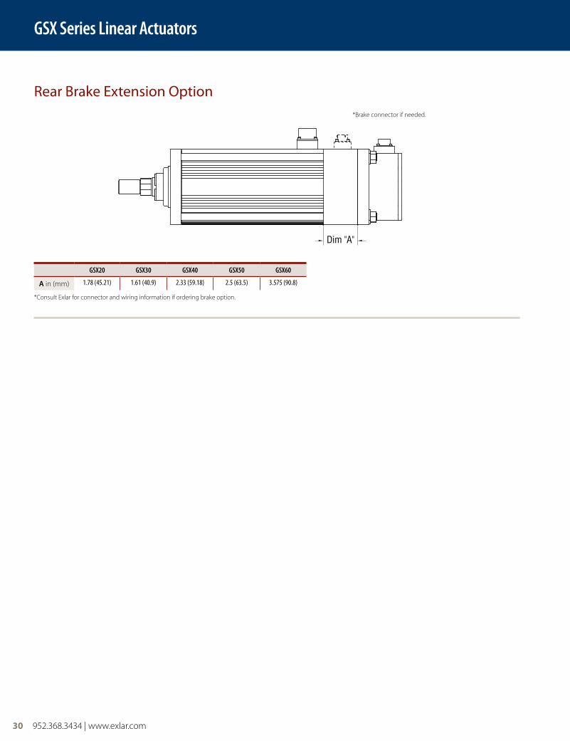
30 952.368.3434 | www.exlar.com
GSX Series Linear Actuators
Dim "A"
Rear Brake Extension Option
*Consult Exlar for connector and wiring information if ordering brake option.
*Brake connector if needed.
GSX20 GSX30 GSX40 GSX50 GSX60
a in (mm) 1.78 (45.21) 1.61 (40.9) 2.33 (59.18) 2.5 (63.5) 3.575 (90.8)
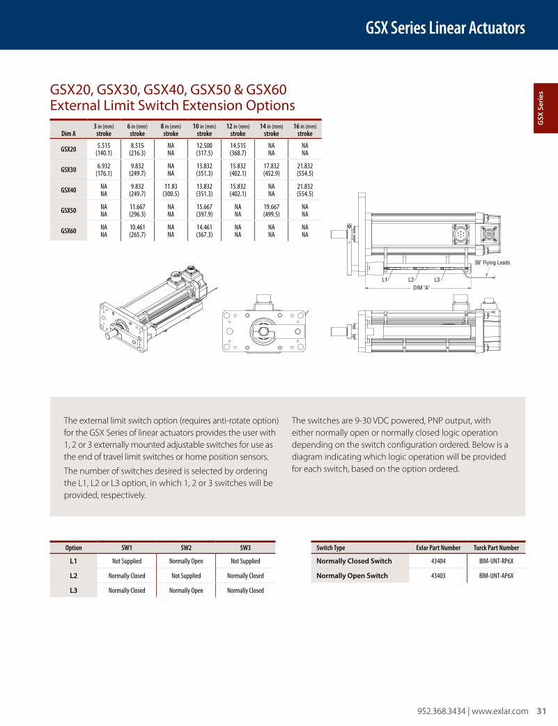
952.368.3434 | www.exlar.com 31
GSX Series Linear Actuators
Option SW1 SW2 SW3 Switch Type Exlar Part Number Turck Part Number
l1 Not Supplied Normally Open Not Supplied normally closed Switch 43404 BIM-UNT-RP6X
l2 Normally Closed Not Supplied Normally Closed normally open Switch 43403 BIM-UNT-AP6X
l3 Normally Closed Normally Open Normally Closed
GSX20, GSX30, GSX40, GSX50 & GSX60 External Limit Switch Extension Options
Dim A3 in (mm)
stroke6 in (mm)
stroke8 in (mm)
stroke10 in (mm)
stroke12 in (mm)
stroke14 in (mm)
stroke16 in (mm)
stroke
GSX20 5.515 (140.1)
8.515 (216.3)
NANA
12.500 (317.5)
14.515 (368.7)
NANA
NANA
GSX30 6.932 (176.1)
9.832 (249.7)
NANA
13.832 (351.3)
15.832 (402.1)
17.832 (452.9)
21.832 (554.5)
GSX40 NANA
9.832 (249.7)
11.83 (300.5)
13.832 (351.3)
15.832 (402.1)
NANA
21.832 (554.5)
GSX50 NANA
11.667 (296.3)
NANA
15.667 (397.9)
NANA
19.667 (499.5)
NANA
GSX60 NANA
10.461 (265.7)
NANA
14.461 (367.3)
NANA
NANA
NANA
The external limit switch option (requires anti-rotate option) for the GSX Series of linear actuators provides the user with 1, 2 or 3 externally mounted adjustable switches for use as the end of travel limit switches or home position sensors.
The number of switches desired is selected by ordering the L1, L2 or L3 option, in which 1, 2 or 3 switches will be provided, respectively.
The switches are 9-30 VDC powered, PNP output, with either normally open or normally closed logic operation depending on the switch configuration ordered. Below is a diagram indicating which logic operation will be provided for each switch, based on the option ordered.
DIM "A"
36" Flying Leads
L1 L2 L3
gSX
Ser
ies
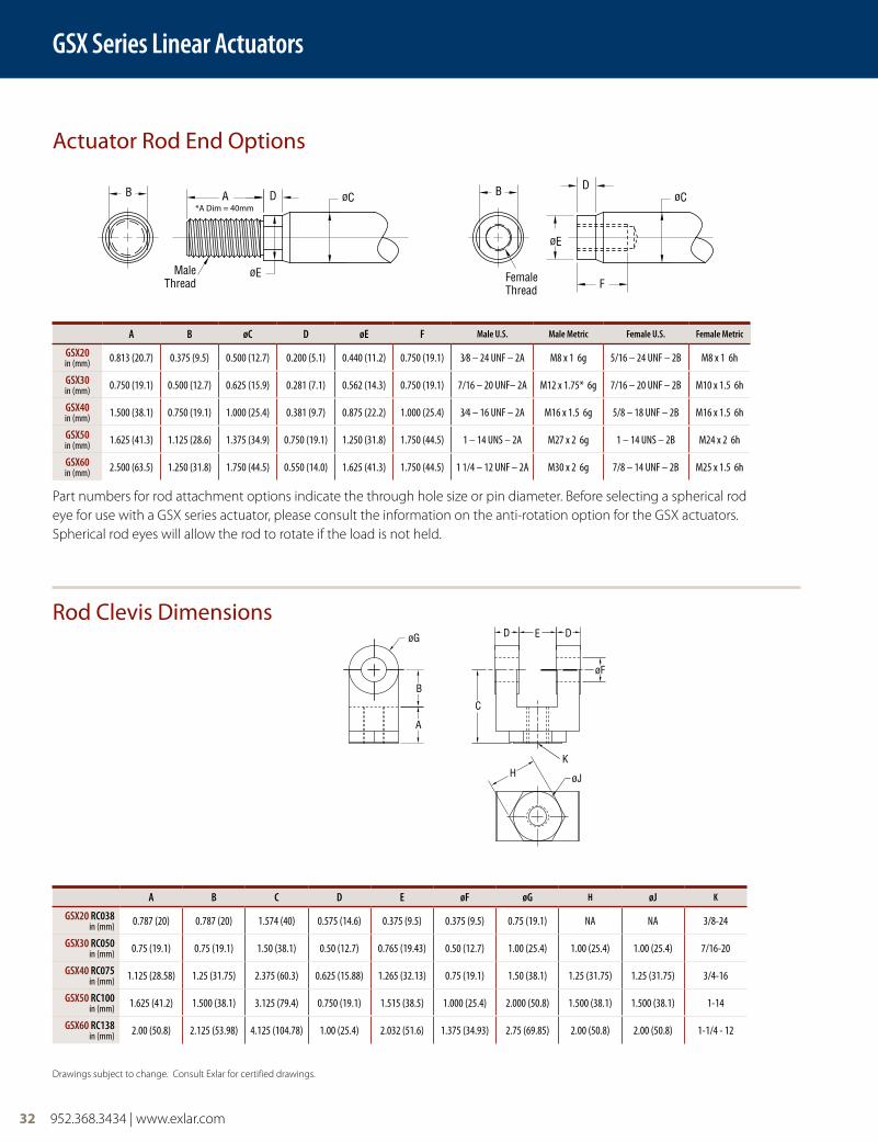
32 952.368.3434 | www.exlar.com
GSX Series Linear Actuators
Part numbers for rod attachment options indicate the through hole size or pin diameter. Before selecting a spherical rod eye for use with a GSX series actuator, please consult the information on the anti-rotation option for the GSX actuators. Spherical rod eyes will allow the rod to rotate if the load is not held.
D DE
øF
C
B
A
øG
H øJ
K
Actuator Rod End Options
Rod Clevis Dimensions
D GD
A øCD
øE
B
MaleThread
B D
øE
F
øC
FemaleThread
*A Dim = 40mm
A B øC D øE F Male U.S. Male Metric Female U.S. Female Metric
GSX20in (mm) 0.813 (20.7) 0.375 (9.5) 0.500 (12.7) 0.200 (5.1) 0.440 (11.2) 0.750 (19.1) 3⁄8 – 24 UNF – 2A M8 x 1 6g 5/16 – 24 UNF – 2B M8 x 1 6h
GSX30in (mm) 0.750 (19.1) 0.500 (12.7) 0.625 (15.9) 0.281 (7.1) 0.562 (14.3) 0.750 (19.1) 7/16 – 20 UNF– 2A M12 x 1.75* 6g 7/16 – 20 UNF – 2B M10 x 1.5 6h
GSX40in (mm) 1.500 (38.1) 0.750 (19.1) 1.000 (25.4) 0.381 (9.7) 0.875 (22.2) 1.000 (25.4) 3⁄4 – 16 UNF – 2A M16 x 1.5 6g 5/8 – 18 UNF – 2B M16 x 1.5 6h
GSX50in (mm) 1.625 (41.3) 1.125 (28.6) 1.375 (34.9) 0.750 (19.1) 1.250 (31.8) 1.750 (44.5) 1 – 14 UNS – 2A M27 x 2 6g 1 – 14 UNS – 2B M24 x 2 6h
GSX60in (mm) 2.500 (63.5) 1.250 (31.8) 1.750 (44.5) 0.550 (14.0) 1.625 (41.3) 1.750 (44.5) 1 1/4 – 12 UNF – 2A M30 x 2 6g 7/8 – 14 UNF – 2B M25 x 1.5 6h
A B C D E øF øG H øJ K
GSX20 RC038in (mm) 0.787 (20) 0.787 (20) 1.574 (40) 0.575 (14.6) 0.375 (9.5) 0.375 (9.5) 0.75 (19.1) NA NA 3/8-24
GSX30 RC050in (mm) 0.75 (19.1) 0.75 (19.1) 1.50 (38.1) 0.50 (12.7) 0.765 (19.43) 0.50 (12.7) 1.00 (25.4) 1.00 (25.4) 1.00 (25.4) 7/16-20
GSX40 RC075in (mm) 1.125 (28.58) 1.25 (31.75) 2.375 (60.3) 0.625 (15.88) 1.265 (32.13) 0.75 (19.1) 1.50 (38.1) 1.25 (31.75) 1.25 (31.75) 3/4-16
GSX50 RC100in (mm) 1.625 (41.2) 1.500 (38.1) 3.125 (79.4) 0.750 (19.1) 1.515 (38.5) 1.000 (25.4) 2.000 (50.8) 1.500 (38.1) 1.500 (38.1) 1-14
GSX60 RC138in (mm) 2.00 (50.8) 2.125 (53.98) 4.125 (104.78) 1.00 (25.4) 2.032 (51.6) 1.375 (34.93) 2.75 (69.85) 2.00 (50.8) 2.00 (50.8) 1-1/4 - 12
Drawings subject to change. Consult Exlar for certified drawings.
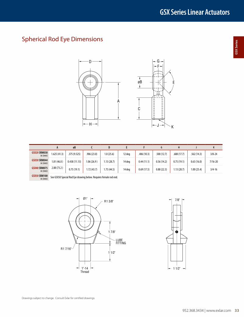
952.368.3434 | www.exlar.com 33
GSX Series Linear Actuators
Spherical Rod Eye Dimensions
A øB C D E F G H J K
GSX20 SRM038in (mm) 1.625 (41.3) .375 (9.525) .906 (23.0) 1.0 (25.6) 12 deg .406 (10.3) .500 (12.7) .688 (17.7) .562 (14.3) 3/8-24
GSX30 SRM044in (mm) 1.81 (46.0 ) 0.438 (11.13) 1.06 (26.9 ) 1.13 (28.7) 14 deg 0.44 (11.1) 0.56 (14.2) 0.75 (19.1) 0.63 (16.0) 7/16-20
GSX40 SRM075in (mm)
2.88 (73.2 ) 0.75 (19.1) 1.72 (43.7) 1.75 (44.5) 14 deg 0.69 (17.5) 0.88 (22.3) 1.13 (28.7) 1.00 (25.4) 3/4-16
GSX50 SRM100in (mm) See GSX50 Special Rod Eye drawing below. Requires female rod end.
Drawings subject to change. Consult Exlar for certified drawings.
D
A
H
FG
øB
C
J K
E
Ø1"R1 3/8"
R1 7/16"1 1/2"
1 7/8"
1"-14Thread
LUBE FITTING
7/8"
1 1/2"
gSX
Ser
ies
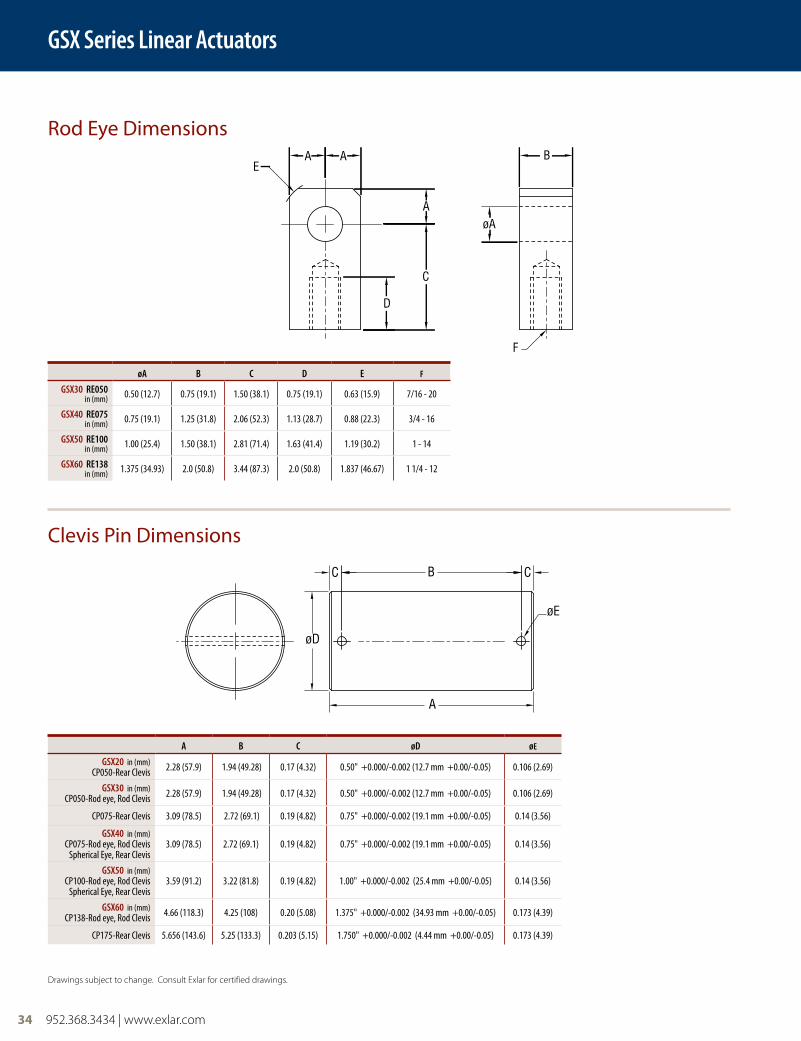
34 952.368.3434 | www.exlar.com
GSX Series Linear Actuators
Rod Eye Dimensions
Clevis Pin Dimensions
øA B C D E F
GSX30 RE050in (mm) 0.50 (12.7) 0.75 (19.1) 1.50 (38.1) 0.75 (19.1) 0.63 (15.9) 7/16 - 20
GSX40 RE075in (mm) 0.75 (19.1) 1.25 (31.8) 2.06 (52.3) 1.13 (28.7) 0.88 (22.3) 3/4 - 16
GSX50 RE100in (mm) 1.00 (25.4) 1.50 (38.1) 2.81 (71.4) 1.63 (41.4) 1.19 (30.2) 1 - 14
GSX60 RE138in (mm) 1.375 (34.93) 2.0 (50.8) 3.44 (87.3) 2.0 (50.8) 1.837 (46.67) 1 1/4 - 12
A B C øD øE
GSX20 in (mm) CP050-Rear Clevis 2.28 (57.9) 1.94 (49.28) 0.17 (4.32) 0.50" +0.000/-0.002 (12.7 mm +0.00/-0.05) 0.106 (2.69)
GSX30 in (mm) CP050-Rod eye, Rod Clevis 2.28 (57.9) 1.94 (49.28) 0.17 (4.32) 0.50" +0.000/-0.002 (12.7 mm +0.00/-0.05) 0.106 (2.69)
CP075-Rear Clevis 3.09 (78.5) 2.72 (69.1) 0.19 (4.82) 0.75" +0.000/-0.002 (19.1 mm +0.00/-0.05) 0.14 (3.56)
GSX40 in (mm) CP075-Rod eye, Rod Clevis
Spherical Eye, Rear Clevis3.09 (78.5) 2.72 (69.1) 0.19 (4.82) 0.75" +0.000/-0.002 (19.1 mm +0.00/-0.05) 0.14 (3.56)
GSX50 in (mm) CP100-Rod eye, Rod Clevis
Spherical Eye, Rear Clevis3.59 (91.2) 3.22 (81.8) 0.19 (4.82) 1.00" +0.000/-0.002 (25.4 mm +0.00/-0.05) 0.14 (3.56)
GSX60 in (mm) CP138-Rod eye, Rod Clevis 4.66 (118.3) 4.25 (108) 0.20 (5.08) 1.375" +0.000/-0.002 (34.93 mm +0.00/-0.05) 0.173 (4.39)
CP175-Rear Clevis 5.656 (143.6) 5.25 (133.3) 0.203 (5.15) 1.750" +0.000/-0.002 (4.44 mm +0.00/-0.05) 0.173 (4.39)
Drawings subject to change. Consult Exlar for certified drawings.
AA
A
B
øA
C
D
F
E
C CB
A
øE
øD
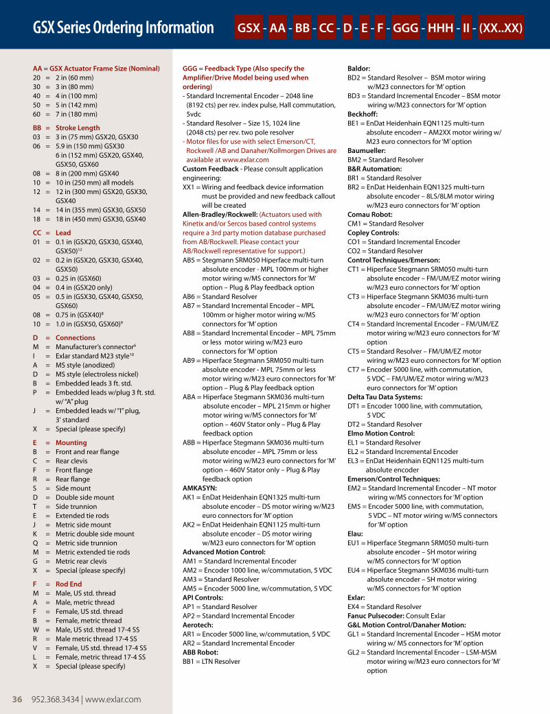
36 952.368.3434 | www.exlar.com
GSX Series Ordering Information
aa = gSX actuator Frame Size (nominal)20 = 2 in (60 mm) 30 = 3 in (80 mm) 40 = 4 in (100 mm)50 = 5 in (142 mm)60 = 7 in (180 mm)
bb = Stroke length03 = 3 in (75 mm) GSX20, GSX3006 = 5.9 in (150 mm) GSX30
6 in (152 mm) GSX20, GSX40, GSX50, GSX60
08 = 8 in (200 mm) GSX4010 = 10 in (250 mm) all models12 = 12 in (300 mm) GSX20, GSX30,
GSX4014 = 14 in (355 mm) GSX30, GSX5018 = 18 in (450 mm) GSX30, GSX40
cc = lead01 = 0.1 in (GSX20, GSX30, GSX40,
GSX50)12
02 = 0.2 in (GSX20, GSX30, GSX40, GSX50)
03 = 0.25 in (GSX60)04 = 0.4 in (GSX20 only)05 = 0.5 in (GSX30, GSX40, GSX50,
GSX60)08 = 0.75 in (GSX40)8
10 = 1.0 in (GSX50, GSX60)9
d = connectionsM = Manufacturer’s connector6
I = Exlar standard M23 style10 A = MS style (anodized)D = MS style (electroless nickel) B = Embedded leads 3 ft. std.P = Embedded leads w/plug 3 ft. std.
w/ “A” plugJ = Embedded leads w/ “I” plug,
3' standardX = Special (please specify)
e = MountingB = Front and rear flangeC = Rear clevisF = Front flangeR = Rear flangeS = Side mountD = Double side mountT = Side trunnionE = Extended tie rodsJ = Metric side mountK = Metric double side mountQ = Metric side trunnionM = Metric extended tie rodsG = Metric rear clevisX = Special (please specify)
F = Rod endM = Male, US std. threadA = Male, metric threadF = Female, US std. threadB = Female, metric threadW = Male, US std. thread 17-4 SSR = Male metric thread 17-4 SSV = Female, US std. thread 17-4 SSL = Female, metric thread 17-4 SS X = Special (please specify)
ggg = Feedback Type (also specify the amplifier/drive Model being used when ordering)- Standard Incremental Encoder – 2048 line
(8192 cts) per rev. index pulse, Hall commutation, 5vdc
- Standard Resolver – Size 15, 1024 line (2048 cts) per rev. two pole resolver
- Motor files for use with select Emerson/CT, Rockwell /AB and Danaher/Kollmorgen Drives are available at www.exlar.com
custom Feedback - Please consult application engineering:XX1 = Wiring and feedback device information
must be provided and new feedback callout will be created
allen-bradley/Rockwell: (Actuators used with Kinetix and/or Sercos based control systems require a 3rd party motion database purchased from AB/Rockwell. Please contact your AB/Rockwell representative for support.)AB5 = Stegmann SRM050 Hiperface multi-turn
absolute encoder - MPL 100mm or higher motor wiring w/MS connectors for ‘M’ option – Plug & Play feedback option
AB6 = Standard ResolverAB7 = Standard Incremental Encoder – MPL
100mm or higher motor wiring w/MS connectors for ‘M’ option
AB8 = Standard Incremental Encoder – MPL 75mm or less motor wiring w/M23 euro connectors for ‘M’ option
AB9 = Hiperface Stegmann SRM050 multi-turn absolute encoder - MPL 75mm or less motor wiring w/M23 euro connectors for ‘M’ option – Plug & Play feedback option
ABA = Hiperface Stegmann SKM036 multi-turn absolute encoder – MPL 215mm or higher motor wiring w/MS connectors for ‘M’ option – 460V Stator only – Plug & Play feedback option
ABB = Hiperface Stegmann SKM036 multi-turn absolute encoder – MPL 75mm or less motor wiring w/M23 euro connectors for ‘M’ option – 460V Stator only – Plug & Play feedback option
aMkaSyn:AK1 = EnDat Heidenhain EQN1325 multi-turn
absolute encoder – DS motor wiring w/M23 euro connectors for ‘M’ option
AK2 = EnDat Heidenhain EQN1125 multi-turn absolute encoder – DS motor wiring w/M23 euro connectors for ‘M’ option
advanced Motion control:AM1 = Standard Incremental Encoder AM2 = Encoder 1000 line, w/commutation, 5 VDCAM3 = Standard ResolverAM5 = Encoder 5000 line, w/commutation, 5 VDCaPI controls:AP1 = Standard ResolverAP2 = Standard Incremental Encoder aerotech:AR1 = Encoder 5000 line, w/commutation, 5 VDCAR2 = Standard Incremental Encoderabb Robot:BB1 = LTN Resolver
baldor:BD2 = Standard Resolver – BSM motor wiring
w/M23 connectors for ‘M’ option BD3 = Standard Incremental Encoder – BSM motor
wiring w/M23 connectors for ‘M’ optionbeckhoff:BE1 = EnDat Heidenhain EQN1125 multi-turn
absolute encoderr – AM2XX motor wiring w/M23 euro connectors for ‘M’ option
baumueller:BM2 = Standard Resolverb&R automation:BR1 = Standard ResolverBR2 = EnDat Heidenhain EQN1325 multi-turn
absolute encoder – 8LS/8LM motor wiring w/M23 euro connectors for ‘M’ option
comau Robot:CM1 = Standard Resolvercopley controls:CO1 = Standard Incremental EncoderCO2 = Standard Resolvercontrol Techniques/emerson:CT1 = Hiperface Stegmann SRM050 multi-turn
absolute encoder – FM/UM/EZ motor wiring w/M23 euro connectors for ‘M’ option
CT3 = Hiperface Stegmann SKM036 multi-turn absolute encoder – FM/UM/EZ motor wiring w/M23 euro connectors for ‘M’ option
CT4 = Standard Incremental Encoder – FM/UM/EZ motor wiring w/M23 euro connectors for ‘M’ option
CT5 = Standard Resolver – FM/UM/EZ motor wiring w/M23 euro connectors for ‘M’ option
CT7 = Encoder 5000 line, with commutation, 5 VDC – FM/UM/EZ motor wiring w/M23 euro connectors for ‘M’ option
delta Tau data Systems:DT1 = Encoder 1000 line, with commutation,
5 VDCDT2 = Standard Resolverelmo Motion control:EL1 = Standard ResolverEL2 = Standard Incremental EncoderEL3 = EnDat Heidenhain EQN1125 multi-turn
absolute encoderemerson/control Techniques:EM2 = Standard Incremental Encoder – NT motor
wiring w/MS connectors for ‘M’ optionEM5 = Encoder 5000 line, with commutation,
5 VDC – NT motor wiring w/MS connectors for ‘M’ option
elau:EU1 = Hiperface Stegmann SRM050 multi-turn
absolute encoder – SH motor wiring w/MS connectors for ‘M’ option
EU4 = Hiperface Stegmann SKM036 multi-turn absolute encoder – SH motor wiring w/MS connectors for ‘M’ option
exlar:EX4 = Standard ResolverFanuc Pulsecoder: Consult Exlarg&l Motion control/danaher Motion:GL1 = Standard Incremental Encoder – HSM motor
wiring w/ MS connectors for ‘M’ optionGL2 = Standard Incremental Encoder – LSM-MSM
motor wiring w/M23 euro connectors for ‘M’ option
gSX - aa - bb - cc - d - e - F - ggg - hhh - II - (XX..XX)
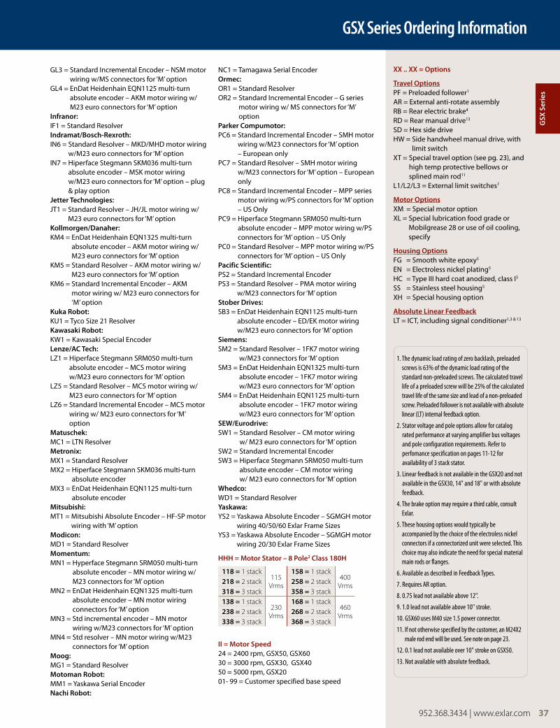
952.368.3434 | www.exlar.com 37
GSX Series Ordering Information
GL3 = Standard Incremental Encoder – NSM motor wiring w/MS connectors for ‘M’ option
GL4 = EnDat Heidenhain EQN1125 multi-turn absolute encoder – AKM motor wiring w/M23 euro connectors for ‘M’ option
Infranor:IF1 = Standard ResolverIndramat/bosch-Rexroth:IN6 = Standard Resolver – MKD/MHD motor wiring
w/M23 euro connectors for ‘M’ optionIN7 = Hiperface Stegmann SKM036 multi-turn
absolute encoder – MSK motor wiring w/M23 euro connectors for ‘M’ option – plug & play option
Jetter Technologies:JT1 = Standard Resolver – JH/JL motor wiring w/
M23 euro connectors for ‘M’ optionkollmorgen/danaher:KM4 = EnDat Heidenhain EQN1325 multi-turn
absolute encoder – AKM motor wiring w/M23 euro connectors for ‘M’ option
KM5 = Standard Resolver – AKM motor wiring w/M23 euro connectors for ‘M’ option
KM6 = Standard Incremental Encoder – AKM motor wiring w/ M23 euro connectors for ‘M’ option
kuka Robot:KU1 = Tyco Size 21 Resolverkawasaki Robot:KW1 = Kawasaki Special Encoderlenze/ac Tech: LZ1 = Hiperface Stegmann SRM050 multi-turn
absolute encoder – MCS motor wiring w/M23 euro connectors for ‘M’ option
LZ5 = Standard Resolver – MCS motor wiring w/ M23 euro connectors for ‘M’ option
LZ6 = Standard Incremental Encoder – MCS motor wiring w/ M23 euro connectors for ‘M’ option
Matuschek:MC1 = LTN ResolverMetronix:MX1 = Standard ResolverMX2 = Hiperface Stegmann SKM036 multi-turn
absolute encoderMX3 = EnDat Heidenhain EQN1125 multi-turn
absolute encoderMitsubishi:MT1 = Mitsubishi Absolute Encoder – HF-SP motor
wiring with ‘M’ optionModicon:MD1 = Standard ResolverMomentum:MN1 = Hyperface Stegmann SRM050 multi-turn
absolute encoder – MN motor wiring w/M23 connectors for ‘M’ option
MN2 = EnDat Heidenhain EQN1325 multi-turn absolute encoder – MN motor wiring connectors for ‘M’ option
MN3 = Std incremental encoder – MN motor wiring w/M23 connectors for ‘M’ option
MN4 = Std resolver – MN motor wiring w/M23 connectors for ‘M’ option
Moog:MG1 = Standard ResolverMotoman Robot:MM1 = Yaskawa Serial Encodernachi Robot:
NC1 = Tamagawa Serial Encoderormec:OR1 = Standard Resolver OR2 = Standard Incremental Encoder – G series
motor wiring w/ MS connectors for ‘M’ option
Parker compumotor:PC6 = Standard Incremental Encoder – SMH motor
wiring w/M23 connectors for ‘M’ option – European only
PC7 = Standard Resolver – SMH motor wiring w/M23 connectors for ‘M’ option – European only
PC8 = Standard Incremental Encoder – MPP series motor wiring w/PS connectors for ‘M’ option – US Only
PC9 = Hiperface Stegmann SRM050 multi-turn absolute encoder – MPP motor wiring w/PS connectors for ‘M’ option – US Only
PC0 = Standard Resolver – MPP motor wiring w/PS connectors for ‘M’ option – US Only
Pacific Scientific:PS2 = Standard Incremental EncoderPS3 = Standard Resolver – PMA motor wiring
w/M23 connectors for ‘M’ optionStober drives:SB3 = EnDat Heidenhain EQN1125 multi-turn
absolute encoder – ED/EK motor wiring w/M23 euro connectors for ‘M’ option
Siemens:SM2 = Standard Resolver – 1FK7 motor wiring
w/M23 connectors for ‘M’ optionSM3 = EnDat Heidenhain EQN1325 multi-turn
absolute encoder – 1FK7 motor wiring w/M23 euro connectors for ‘M’ option
SM4 = EnDat Heidenhain EQN1125 multi-turn absolute encoder – 1FK7 motor wiring w/M23 euro connectors for ‘M’ option
Sew/eurodrive:SW1 = Standard Resolver – CM motor wiring
w/ M23 euro connectors for ‘M’ optionSW2 = Standard Incremental EncoderSW3 = Hiperface Stegmann SRM050 multi-turn
absolute encoder – CM motor wiring w/ M23 euro connectors for ‘M’ option
whedco:WD1 = Standard Resolveryaskawa:YS2 = Yaskawa Absolute Encoder – SGMGH motor
wiring 40/50/60 Exlar Frame SizesYS3 = Yaskawa Absolute Encoder – SGMGH motor
wiring 20/30 Exlar Frame Sizes
hhh = Motor Stator – 8 Pole2 class 180h
II = Motor Speed24 = 2400 rpm, GSX50, GSX60 30 = 3000 rpm, GSX30, GSX4050 = 5000 rpm, GSX2001- 99 = Customer specified base speed
XX .. XX = options
Travel optionsPF = Preloaded follower1
AR = External anti-rotate assemblyRB = Rear electric brake4
RD = Rear manual drive13
SD = Hex side driveHW = Side handwheel manual drive, with
limit switchXT = Special travel option (see pg. 23), and
high temp protective bellows or splined main rod11
L1/L2/L3 = External limit switches7
Motor optionsXM = Special motor optionXL = Special lubrication food grade or
Mobilgrease 28 or use of oil cooling, specify
housing optionsFG = Smooth white epoxy5 EN = Electroless nickel plating5
HC = Type III hard coat anodized, class I5 SS = Stainless steel housing5 XH = Special housing option
absolute linear FeedbackLT = ICT, including signal conditioner1,3 & 13
1. The dynamic load rating of zero backlash, preloaded screws is 63% of the dynamic load rating of the standard non-preloaded screws. The calculated travel life of a preloaded screw will be 25% of the calculated travel life of the same size and lead of a non-preloaded screw. Preloaded follower is not available with absolute linear (LT) internal feedback option.
2. Stator voltage and pole options allow for catalog rated performance at varying amplifier bus voltages and pole configuration requirements. Refer to perfomance specification on pages 11-12 for availability of 3 stack stator.
3. Linear feedback is not available in the GSX20 and not available in the GSX30, 14" and 18" or with absolute feedback.
4. The brake option may require a third cable, consult Exlar.
5. These housing options would typically be accompanied by the choice of the electroless nickel connectors if a connectorized unit were selected. This choice may also indicate the need for special material main rods or flanges.
6. Available as described in Feedback Types.
7. Requires AR option.
8. 0.75 lead not available above 12".
9. 1.0 lead not available above 10" stroke.
10. GSX60 uses M40 size 1.5 power connector.
11. If not otherwise specified by the customer, an M24X2 male rod end will be used. See note on page 23.
12. 0.1 lead not available over 10" stroke on GSX50.
13. Not available with absolute feedback.
gSX
Ser
ies
118 = 1 stack115
Vrms
158 = 1 stack400
Vrms218 = 2 stack 258 = 2 stack318 = 3 stack 358 = 3 stack138 = 1 stack
230 Vrms
168 = 1 stack460
Vrms238 = 2 stack 268 = 2 stack338 = 3 stack 368 = 3 stack