FSU 995 FA - atecorp.com · Parameter editing review ... The FSU 995 FA is a precision instrument,...
85
FSU 995 FA User’s manual 133ST010R1A Advanced Test Equipment Rentals www.atecorp.com 800-404-ATEC (2832) ® E s t a blishe d 1 9 8 1
Transcript of FSU 995 FA - atecorp.com · Parameter editing review ... The FSU 995 FA is a precision instrument,...

FSU 995 FAUser’s manual
133ST010R1AAdvanced Test Equipment Rentalswww.atecorp.com 800-404-ATEC (2832)
®
Established 1981

1
User’s manual for the FSU 995 FAsingle fiber fusion splicer by Ericsson

2

3
Table of contents
Introduction ..................................................................................................................... 4Safety Information ........................................................................................................... 5Description of the FSU 995 FA ........................................................................................ 6Setting up the splicer ...................................................................................................... 8
BASIC OPERATION......................................................................................................... 9Splicing quick guide ........................................................................................... 9Fiber preparation .............................................................................................. 10Splicer preparation ........................................................................................... 12Splicing mode and program selection .............................................................. 14Automode splicing............................................................................................ 17Manual mode splicing ...................................................................................... 18Splice evaluation .............................................................................................. 21Splice protection .............................................................................................. 23
ADVANCED OPERATION .............................................................................................. 25Fusion program structure ................................................................................. 25
Overview .......................................................................................... 25Program name ................................................................................. 26Fiber type......................................................................................... 26Splicing process .............................................................................. 28Program parameters ........................................................................ 36
Pre-defined programs: Programs 01 - 10 ......................................................... 41Program editing: Programs 11 - 50 ................................................................... 43Parameter editing review ................................................................................. 53Special functions.............................................................................................. 55
Advanced splicing parameters ........................................................ 55Service functions: #-button ............................................................. 57Advanced hot image analysis ......................................................... 60Quick character selection ............................................................... 61Global parameters: Program 00 ...................................................... 61
Upload / Download Software ........................................................................................ 65
Maintenance ................................................................................................................. 66Power connection ............................................................................................ 66Fiber clamps and V-grooves ............................................................................. 67Electrodes ........................................................................................................ 68Mirror one ......................................................................................................... 70Maintenance time table ................................................................................... 70
AppendicesA-Troubleshooting ............................................................................................ 71B-Technical Data .............................................................................................. 74C-Parameter and program editing flow charts ................................................. 75
Index ............................................................................................................................. 80Ericsson representatives............................................................................................... 82
Table of contents
4
Introduction
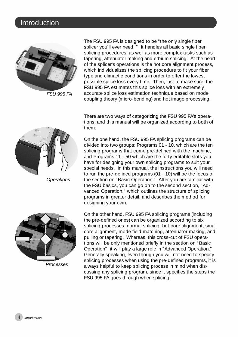
The FSU 995 FA is designed to be “the only single fibersplicer you’ll ever need. ” It handles all basic single fibersplicing procedures, as well as more complex tasks such astapering, attenuator making and erbium splicing. At the heartof the splicer’s operations is the hot core alignment process,which individualizes the splicing procedure to fit your fibertype and climactic conditions in order to offer the lowestpossible splice loss every time. Then, just to make sure, theFSU 995 FA estimates this splice loss with an extremelyaccurate splice loss estimation technique based on modecoupling theory (micro-bending) and hot image processing.
There are two ways of categorizing the FSU 995 FA’s opera-tions, and this manual will be organized according to both ofthem:
On the one hand, the FSU 995 FA splicing programs can bedivided into two groups: Programs 01 - 10, which are the tensplicing programs that come pre-defined with the machine,and Programs 11 - 50 which are the forty editable slots youhave for designing your own splicing programs to suit yourspecial needs. In this manual, the instructions you will needto run the pre-defined programs (01 - 10) will be the focus ofthe section on “Basic Operation.” After you are familiar withthe FSU basics, you can go on to the second section, “Ad-vanced Operation,” which outlines the structure of splicingprograms in greater detail, and describes the method fordesigning your own.
On the other hand, FSU 995 FA splicing programs (includingthe pre-defined ones) can be organized according to sixsplicing processes: normal splicing, hot core alignment, smallcore alignment, mode field matching, attenuator making, andpulling or tapering. Whereas, this cross-cut of FSU opera-tions will be only mentioned briefly in the section on “BasicOperation”, it will play a large role in “Advanced Operation.”Generally speaking, even though you will not need to specifysplicing processes when using the pre-defined programs, it isalways helpful to keep splicing process in mind when dis-cussing any splicing program, since it specifies the steps theFSU 995 FA goes through when splicing.
Operations
FSU 995 FA
Processes
Introduction

5
!
Safety Information
Maintenance Precautions
� Never use hard ob-jects to clean the V-grooves or electrodes.Use the supplied brush,or in the case of the V-grooves, isopropyl alco-hol and cotton swabs.
� Never use acetone forcleaning any part of thesplicer.
� Never use cans withcompressed gas to cleanany part of the splicer.
� Keep the electrodehousing clean and dry atall times.
� Use the electrodecleaning program afterevery time you clean orchange the electrodes,otherwise the arc will beunstable.
Operational Precautions
� Do not use the splicerin locations where thereis a risk of explosion.
� Never touch the elec-trodes when the spliceris on.
� Never open the safetyshield or the power sup-ply during operation.
� Never loosen anyscrews except thosementioned in thismanual, since youmay harm importantadjustments.
� Do not insert objectsother than stripped andcleaned optical fiber orcleaning and mainte-nance tools into thesplicer.
General rule is...
The FSU 995 FA is a precision instrument, and must be treated as such.
Safety Information
Transport and Storage
� Never leave yoursplicer in direct sunlightor in places where itmight be exposed toexcessive heat (such asin vehicles parked in thesun).
� Always transport thesplicer in its carryingcase to avoid damage toits precision parts.
� Keep the humidity to aminimum where thesplicer is stored. Thehumidity must not ex-ceed 95%.
� If moisture forms onthe optics when movingthe splicer from an areawith very cold tempera-ture to a warmer environ-ment, let the splicer sitand warm up beforeusing it.
� Close the safety shieldduring transport.

6
Description of the FSU 995 FA
1
2
3
45
The FSU 995 FA is deliveredin a rugged, cabin-size carry-ing case along with the basicset of tools for splicing, andthis manual.
FSU 995 FA fusion splicerTool set with one electrodebrush, one set of tweezers, aseven piece hexagonal key set,and one hex wrench
Carrying case
Pair of spare electrodes
Two pairs of V-grooves
-Blue (125 �m/1mm)
-Black (250 �m/2mm)
2
3
4
5
Fiber fixture(optional, see p. 23)Holds fiber secureduring removal.
Left V-grooveUsed in fiberalignment. Left fiber clamp
Fixes fiber into V-grooves.
Electrodes/Electrode block
Heat oven(optional, see p. 23)Plug-in unit forstandard heat-shrinksleeves.
Safety shieldFor protectionduring splicingsequence.
Right fiber clampFixes fiber into V-grooves.
Right V-grooveUsed in fiberalignment.
Monitor and buttonsdescribed on nextpage.
1
Description of the FSU 995 FA

7
1 2 3
45
6
On/OffEsc/c
ModeHot Image
YesNoEnter0-90-90-9
Select/#
+-View
To turn splicer on and off.To abort operations and to accessparameters.To change splice modeTo flip through hot images.
To answer “yes” to programming questions.To answer “no” to programming questions.To enter one’s selections.To choose first numerical place.*To choose second numerical place.*To choose third numerical place.*
To check battery and to accessservice parameters.
To adjust focus.To adjust focus.To change content of monitor.
Pro
gram
min
g b
utto
nsM
onito
rC
ontr
ols
Left arrows
Right arrows
Up arrowDown arrow
Gap
Fuse
To move left fiber along its own axis (e.g. toward right fiber).To move right fiber along its own axis (e.g. away from left fiber).
For axial fiber alignment.For axial fiber alignment.
To set a fine gap or close a gap.
To initiate a splicing procedure.
OnOff Esc
*
Mode
HotImage
Yes No Enter 0 - 9 0 - 9 0 - 9 Select#
+
_
View
Focus
1 6A Fuse
Output for video
Auxiliary 12V video output (see Appendix B)
2A Fuse
12V power input
RS 232 (see Appendix B)
2
3
4
5
6
The FSU 995 FA monitor is orga-nized into a viewing area that allowsyou to see the fibers from twodifferent angles, and a text areathat is itself divided into two textfields: a mode field and a messagefield. The mode field informs youwhich mode and programs you areworking with. The message fieldposes questions, gives instructionsand tells you what it is doing.
Fibers from 1st angle
If you press VIEW, you then see thefibers from the 2nd angle.
Mode fieldMessage field
Description of the FSU 995 FA
Buttons
Monitor
Rear panel
For example, to get the number ‘147’, you would press the first button once, the second button 4 times, and the third 7 times.*
FSU 995 FA
GapFuse
RightLeft
Up
Down
FSU 995FA AUTO MODEAUTO ALIGNING/FUSION

8
Setting up the splicer
Set-up checklist
Optical fiber
Fiber holders
Strippers
Cleaner
Cleaver
Cotton swabs
Isopropyl alcohol
Electrode brush
FSU 995 FA fusion splicer
FSU 995 FA manual
V-grooves
Heat-shrink oven
Heat-shrinkable sleeves
Power supply or battery
3
The adjacent set-up check-list is not in any way exhaus-tive, but it does present thebasics you should have athand before sitting down andsplicing.
V-grooves
The FSU 995 FA is delivered with two sets of V-grooves, blueV-grooves and black V-grooves:
Use the blue V-grooves when you intend to clamp on barefiber. They are designed for fiber with tight secondary coat-ing with a cladding diameter of up to 125 �m and secondarycoating diameter of up to 1 mm. (See also p. 11).
Use the black V-grooves when you intend to clamp onprimary coating. They are designed for fiber with a nominalprimary coating of 250 �m, as well as, loose-tube secondarycoated fibers with a tube diameter of up to 2 mm. (See alsop. 11).
It is also possible to order specially designed V-grooves fromEricsson by contacting your local service representative. Ifyou do indeed need to change V-grooves, or install them forthe first time, you should follow the instructions on page 67.
Power connection
The FSU 995 FA can be operated by either a 12 V DC batteryor a power supply unit rated at 50-60 Hz. In both cases thepower cord is connected into the outlet marked PWR on therear panel of the splicer (see also diagram of rear panel onprevious page). If you are using the battery delivered byEricsson, keep in mind that the battery is not charged ondelivery (see p. 66).
Setting up the splicer

9
Fuse
Mode
OnOff
BASIC OPERATION - Quick guide
1
2
Connect the splicer to the power supply ................. 8
Prepare the fibers ..................................................... 10Strip, clean and cleave the fibers.
3 Turn on the splicer and place the fibers ................. 12Note: The splicer will turn off automatically when you re-open thesafety shield after splicing.
4 Select splicing mode and program ......................... 14Choose between the two splicing modes: Automode and Manualmode. (Note that the splicer always starts in Automode when justturned on). A list of the pre-defined splicing programs (01-10) isfound on page 16.
5 Splice the fibers ........................................................ 17Press the fuse button.
6 Check the splice ....................................................... 21Check the splice visually by pressing VIEW and scrolling throughstored images. Evaluate the splice quantitaly by taking note of theestimated splice loss.
7 Protect the splice ..................................................... 23Protect the splice with a heat-shrinkable sleeve.
The following steps outline basic operation of the FSU 995 FA,and refer to the pages where they are explained in greater detail.
BASIC OPERATION - Quick guide

10
Fiber preparation
Slip on a heat-shrinkable sleeve1Easily forgotten, yet so frustrating. Remember to always slipa heat-shrinkable sleeve onto one of the fibers at the begin-ning of fiber preparation.
Strip the fiber2First remove at least 50mm of secondary coating (true forboth tight and loose tube secondary coating) with a stripperappropriate to the type of coating you have. Then removearound 25 mm of the primary coating with a stripper de-signed for primary coating. (See also pictures below).
It is important that you do not put undue stress on thefibers by bending or crimping them.
v
Illustrations of strippers for secondary and primary coating
BASIC OPERATION - Fiber preparation
Loose tube secondary coating Tight secondary coating Primary coating
Clean the fiber3Clean the bare fibers with a tissue or a pair of cotton swabssoaked in propanol or ethanol.
It is important that from this point on you are very carefulwith the fibers to ensure that they do not become dirtyagain (such as laying them down on a dusty working surface,or even waving them around in the air).
It is also a good idea at this stage to check to be sure the V-grooves are clean, and if not, wipe them down as well.
11
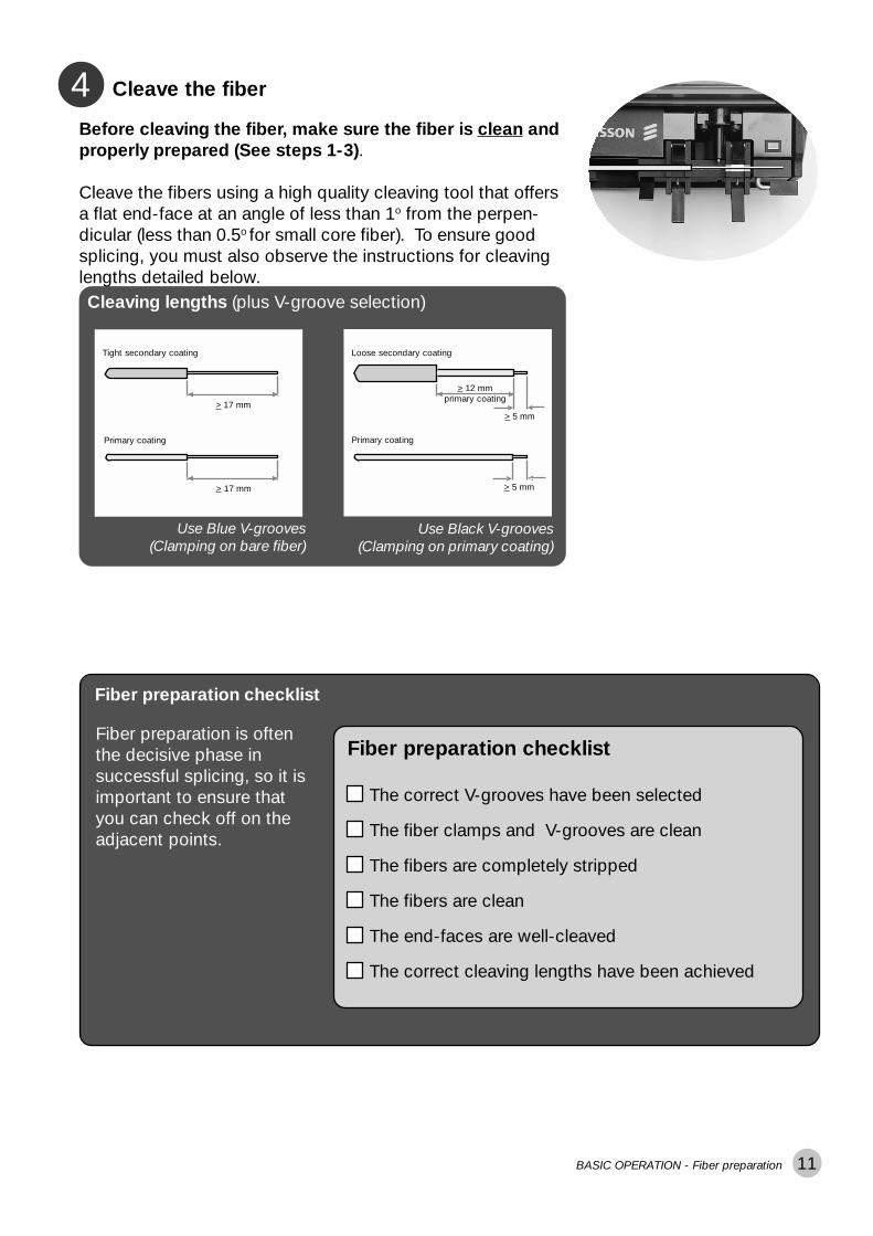
Cleave the fiber4Before cleaving the fiber, make sure the fiber is clean andproperly prepared (See steps 1-3).
Cleave the fibers using a high quality cleaving tool that offersa flat end-face at an angle of less than 1o from the perpen-dicular (less than 0.5o for small core fiber). To ensure goodsplicing, you must also observe the instructions for cleavinglengths detailed below.Cleaving lengths (plus V-groove selection)
Use Blue V-grooves(Clamping on bare fiber)
Use Black V-grooves(Clamping on primary coating)
Loose secondary coating
> 12 mmprimary coating
> 5 mm
> 5 mm
Primary coating
Tight secondary coating
Primary coating
> 17 mm
> 17 mm
Fiber preparation checklist
The correct V-grooves have been selected
The fiber clamps and V-grooves are clean
The fibers are completely stripped
The fibers are clean
The end-faces are well-cleaved
The correct cleaving lengths have been achieved
Fiber preparation checklist
Fiber preparation is oftenthe decisive phase insuccessful splicing, so it isimportant to ensure thatyou can check off on theadjacent points.
BASIC OPERATION - Fiber preparation

12
OnOff
Splicer preparation
Turn on the splicer1Turn on the splicer by pressing the ON/OFF button in theupper left-hand corner. (Remember that the splicer will turnoff automatically when you open the safety shield after splic-ing.)
The splicer always starts in Automode, and thus will read“FSU 995 FA AUTO MODE” in the mode field. In the mes-sage field you will get a message telling you that it is calibrat-ing parameters. Once calibration is completed, the splicerwill tell you to “INSERT FIBERS” and to “CLOSE SAFETYSHIELD.”
BASIC OPERATION - Splicer preparation
FSU 995 FA AUTO MODEPARAMETER UPDATING...
CLOSE SAFETY SHIELD
“ “INSERT FIBERS
Insert fibers2Place the fibers into the V-grooves until they are visible in themonitor, and then close the clamps. Make sure to avoidsliding the fibers along the V-grooves, but rather positionthem over the V-grooves and then tilt them down into place(see picture below).
Proper (and not so proper) insertion of the fibers:
21
13
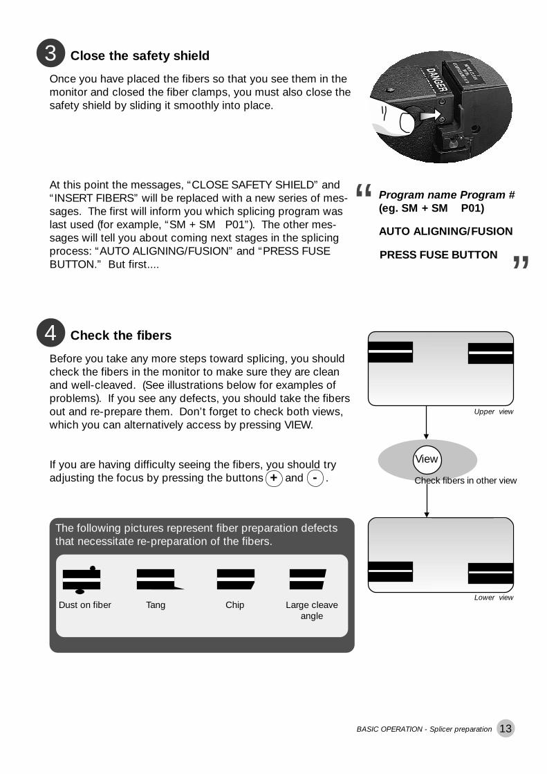
Close the safety shield3Once you have placed the fibers so that you see them in themonitor and closed the fiber clamps, you must also close thesafety shield by sliding it smoothly into place.
At this point the messages, “CLOSE SAFETY SHIELD” and“INSERT FIBERS” will be replaced with a new series of mes-sages. The first will inform you which splicing program waslast used (for example, “SM + SM P01”). The other mes-sages will tell you about coming next stages in the splicingprocess: “AUTO ALIGNING/FUSION” and “PRESS FUSEBUTTON.” But first....
Program name Program #(eg. SM + SM P01)
PRESS FUSE BUTTON
“ “AUTO ALIGNING/FUSION
Check the fibers4Before you take any more steps toward splicing, you shouldcheck the fibers in the monitor to make sure they are cleanand well-cleaved. (See illustrations below for examples ofproblems). If you see any defects, you should take the fibersout and re-prepare them. Don’t forget to check both views,which you can alternatively access by pressing VIEW.
If you are having difficulty seeing the fibers, you should tryadjusting the focus by pressing the buttons and .-+
View
Check fibers in other view
Upper view
Lower viewDust on fiber Tang Chip Large cleave
angle
The following pictures represent fiber preparation defectsthat necessitate re-preparation of the fibers.
BASIC OPERATION - Splicer preparation

14
Splicing mode and program selection
Select splicing mode1
Though the splicer is saying in the message field to “PRESSFUSE BUTTON,” you should make sure the correct splicingmode and program are selected.
As mentioned earlier, the default splicing mode is Automode,and this will be the mode the splicer is in when you just turn iton. In Automode, the splicer automatically carries out fiberalignment and initiates fusion. However, if you want to manu-ally align the fibers and initialize splicing, you can change toManual mode by pushing the MODE button. The mode fieldwill then read to “FSU 995 FA MANUAL MODE.” To changeback to Automode, just push MODE again. Remember thatyou can always check which mode you are in during splicerpreparation by reading what is displayed in the mode field.
Mode
Change splicing mode
FSU 995 FA MANUAL MODE
FSU 995 FA AUTO MODE
“ “toggle between by pushing MODE
Select splicing program2In this section on Basic Operation, we are only going to usethe pre-defined programs (Programs 01-10) as examples, butyou would follow the same selection procedure if you wantedto load in one of your own programs created through theinstructions outlined in the section on Advanced Operation.
A The first step is to press the ENTER button. At this pointboth the mode and the message field will change. The modefield will display the current splicing program, and the mes-sage field will ask you if you want to change it. For the pur-poses of demonstration, we are going to assume that thecurrent splicing program is program 01, NORMAL SM +SM.
B If you press Yes , the message field will then be open foryou to enter a new program.
If you press No , you will jump to step F.
Enter
To change splicing program
“
“
NORMAL SM + SM P01NEW PROGRAM?
Yes
cont., next page
BASIC OPERATION - Splicing mode and program selection
To see a list over the pre-defined programs (Programs 01-10), you can either look on page 16 of this manual, orfollow the instruction in optional step BB on the next pageas to how you can access the screen-viewer.
Confirm wish to change
15
����������� �� ������� ������������ ������������� ���������������� �������������� ������������� ��������������� ��������������� ����������������� ��
��������
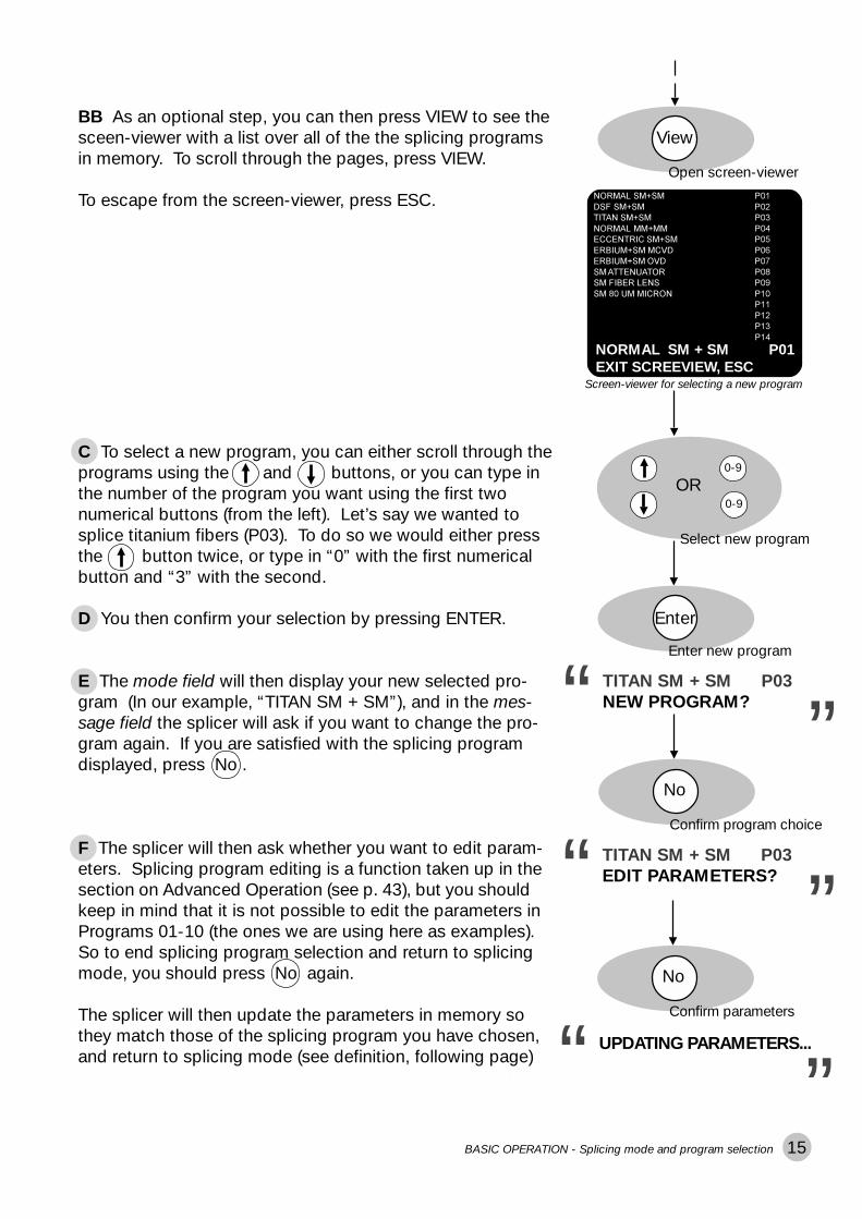
BB As an optional step, you can then press VIEW to see thesceen-viewer with a list over all of the the splicing programsin memory. To scroll through the pages, press VIEW.
To escape from the screen-viewer, press ESC.
View
Screen-viewer for selecting a new program
0-9
0-9
OR
Select new program
C To select a new program, you can either scroll through theprograms using the and buttons, or you can type inthe number of the program you want using the first twonumerical buttons (from the left). Let’s say we wanted tosplice titanium fibers (P03). To do so we would either pressthe button twice, or type in “0” with the first numericalbutton and “3” with the second.
D You then confirm your selection by pressing ENTER.
E The mode field will then display your new selected pro-gram (In our example, “TITAN SM + SM”), and in the mes-sage field the splicer will ask if you want to change the pro-gram again. If you are satisfied with the splicing programdisplayed, press No .
F The splicer will then ask whether you want to edit param-eters. Splicing program editing is a function taken up in thesection on Advanced Operation (see p. 43), but you shouldkeep in mind that it is not possible to edit the parameters inPrograms 01-10 (the ones we are using here as examples).So to end splicing program selection and return to splicingmode, you should press No again.
The splicer will then update the parameters in memory sothey match those of the splicing program you have chosen,and return to splicing mode (see definition, following page)Tosee a list over the pre-defined programs (Programs 01-10),you can either look on page 16 of this manual, or follow theinstruction in optional step BB on the next page as to howyou can access the screen-viewer.
Enter
“
“
TITAN SM + SM P03NEW PROGRAM?
No
“
“
TITAN SM + SM P03EDIT PARAMETERS?
No
Enter new program
Open screen-viewer
BASIC OPERATION - Splicing mode and program selection
Confirm program choice
Confirm parameters
“
“
UPDATING PARAMETERS...
NORMAL SM + SM P01EXIT SCREEVIEW, ESC

16
1250$/�60�60 ��3��'6)�60�60 3��7,7$1�60�60 ��3��1250$/�00�00 3��(&&(175,&�60�60 ��3��(5%,80�60�0&9' 3��(5%,80�'6)�29' ��3��60�$77(18$725 ��3��60�),%(5�/(16 3��60����80�0,&521 ��3��
��3����3��3����3��
N O R M A L S M + S M P 0 1N E W P R O G R A M ?
����������� ��� ������������ ���� ���� ���� �������� ���� ��������������� ��� �������������� ���� ��������������� ��� �������������� ���� ��������������� ��� �������������� ���� ��������� ��� ��
���� �� ��������������������
Viewing splicing program parameters
If you wish to look at a listing of the splicing program param-eters for a particular program you should press ENTER, as ifyou wanted to change splicing program, and then, ratherthan answer “Yes” or “No” to the question “New program?,”press VIEW. This will bring up the screen-viewer for theprogram in memory (see adjacent example). You can flipthrough pages by pressing VIEW, and when you are finishedreviewing the parameters, you press ENTER to exit thescreen-viewer (or press YES or NO, thereby directly enteringthe sequence for splicing program selection at step B, see p.14). You should keep in mind, though, that this is only anoption for non-confidential programs.
Splicing programs 01-10
* Splicing processes are explained in the section on Advanced Operation, see p. 28.
**
Screen-viewer with parameters forProgram 01
BASIC OPERATION - Splicing mode and program selection
Program Name Prog. No. Fiber type Splicing process*
NORMAL SM + SM 01 Standard single fiber Normal splicing
DSF SM + SM 02 Depressed cladding fiber Normal splicing
TITAN SM + SM 03 Titanium fiber Normal splicing
NORMAL MM + MM 04 Mulitmode fiber Normal splicing
ECCENTRIC SM + SM 05 Standard single fiber Hot core alignment
with eccentric core
ERBIUM + SM MCVD** 06 Erbium fiber with Mode field matching
single fiber
ERBIUM + DSF OVD** 07 Erbium fiber with Mode field matching
dispersion shifted fiber
SM ATTENUATOR 08 Standard single fiber Attenuator making
SM FIBER LENS 09 Standard single fiber Pulling or tapering
SM 80 UM MICRON 10 Single fiber with Normal splicing
80 �m core
MCVD and OVD refer to fiber production methods, and respectively stand for“Modified Chemical Vapor Deposition” and “Outside Vapor Deposition.”
Splicing modeThe term “splicing mode” in singular is not to be confusedwith the two splicing modes: Automode and Manual mode.When the FSU 995 is “in splicing mode,” or “returns tosplicing mode,” it means that it is ready to splice on yourcommand. In short, it represents a state of splicing readi-ness. The FSU 995 FA exits splicing mode whenever youpress ENTER to select a program or to edit a program.

17
At this point you should have chosen Automode for thesplicing mode (see p. 14), and a splicing program. Continu-ing with the example taken up in the section on splicingprogram selection, we will assume you have chosen Program03. This will give you the adjacent screen, with “FSU 975 FAAUTO MODE” in the mode field and the program name andprogram number in the message field.
FSU 995 FA AUTO MODETITAN SM + SM P03
Once the fibres are in place and the safety shield has beenclosed, the splicer will then display a series of messages inthe message field that tell you that it is ready.
AUTO ALIGNING/FUSION
PRESS FUSE BUTTON“ “
Splicer ready1
Automode splicing
Start splicing2Fuse
Start automatic splicingTo start the automatic splicing sequence, press FUSE . Thesplicer will then automatically align the fibers roughly, pre-fuses, focuses the view, performs fine alignment, and finallyfuse the fibres. TITAN SM + SM P03
ROUGH ALIGNMENT
PREFUSION WILL START
ROUGH ALIGNMENT
ALIGNING FIBERS
SPLICING WILL START
SPLICING...
“
“
During the entire sequence the chosen splicing program willbe displayed in the mode field (in our example, “TITAN SM +SM P03”), while in the message field the splicer will keep youabreast of what it is doing.
If at any point the splicer cannot carry out some part of theautomatic sequence, a fault message will appear in themessage field. If this occurs you should look at Trouble-shooting in Appendix A, p. 71.
You can interrupt the automatic sequence before the fibersare fused by pressing the button. Press FUSE to re-startthe splicing sequence. *
BASIC OPERATION - Automode splicing

18
At this point you should have chosen Manual mode for thesplicing mode (see p.14), and a splicing program. To continueour example, we will assume you have chosen Program 03for titanium fiber splicing. This will give you the adjacentscreen, with “FSU 995 FA MANUAL MODE” in the mode fieldand the program name (“TITAN SM + SM”) and programnumber (P03) in the message field.
The splicer will then display a series of messages in themessage field that tell you that it is ready.
READY FOR PREFUSING
PRESS FUSE BUTTON“ “
Splicer ready1
Roughly align fibers2In order to roughly align the fibers with respect to each other,you should alternately press the and buttons for boththe right and left fibers until the outer edges of the fibers lineup.
When you think the fibers are lined up, you can start bringingthe fibers towards each other by alternatively pressing theand buttons for each of the fibers. Your goal is a gapequivalent to half a diameter of a fiber, centered horizontallyin the monitor (see illustration below).
You should then press the VIEW button to ensure that thegap is also correct from the other camera angle.
+
After rough alignment the situation should be as follows:the outer edges of the fibers line up, and the gap betweentheir end-faces is the width of half a fiber diameter, andcentered on the monitor.
Outer diameter alignment
+
Gap alignment
View
Check gap in other view
Gapcentered
Gap width of halfa fiber diameter
Outer edges lined up
Manual mode splicing
FSU 995 FA MANUAL MODETITAN SM + SM P03
BASIC OPERATION - Manual mode splicing

19
Prefuse3Fuse
Start prefusionOnce the fibers are rough-aligned, you press the FUSE but-ton. During prefusion the fibers are cleaned by low levelheating.
Inspect fibers4This is your last chance to check the fibers before splicing, soyou should switch between the two viewing angles by press-ing VIEW button, looking for dust or any other imperfections.If dust remains, or you see any other problems you shouldabort the splicing procedure and re-prepare the fibers. Forexamples of problems you should watch out for, see p 13.
View
Check from both angles
Adjust fiber alignment5Now that you have assured yourself that the fibers are cleanand of good quality, you can fine-tune their alignment. Inorder to set the gap, you use the and buttons, bringingthe fibers as close together as possible without overlap.
You then briefly press the GAP button. The resulting gapshould be as narrow as possible, but still wide enough toallow for free movement of the fibers up and down (seeillustration on next page).
Using the and buttons you can now fine-tune thealignment of the outer fiber edges, making sure that the twofibers line up straight across the screen.
If at any point, you feel the view is not clear, use the and buttons to improve the focus.
Do not forget to adjust the fiber alignment from both cameraangles, which you can toggle between by pressing VIEW.
+
Align along x-axis
Gap
Set gap
Align outer edges
View
Check from both angles
+
READY FOR SPLICING
PRESS FUSE BUTTON“ “
After prefusion is complete the splicer sends new messagesto the message field, telling you it is waiting for you to com-plete final inspection and alignment.
-+
BASIC OPERATION - Manual mode splicing
The last movement before you set the gap must be tomove the fibers inwards (closer together).
After you have set the gap, do not press the andbuttons.

20
After fine-tuning the alignment, and before fusion, thealignment should be as follows: the outer edges of thefibers line up, and the gap between their end-faces iscentered on the monitor and as small as possible whilestill allowing for up and down movement of the fibers.
Gap centeredand as narrow as
possible
Outer edges lined up
Fuse6When the fibers are aligned to your satisfaction, you canpress the FUSE button and start fusion. The splicer willfollow the splicing program you chose earlier: in our case,program 03.
As the FSU 995 FA splices your fibers, it will read “Splicing....”in the message field.
Fuse
Fuse fibers
“
“
SPLICING...
Check the splice7Once the splicing sequence is complete, you need to checkthe splice. The steps for this procedure are outlined in thefollowing section.
BASIC OPERATION - Manual mode splicing

21BASIC OPERATION - Splice evaluation
After the splicing sequence is complete, the splicer estimatesthe splice loss and displays it in the mode field.
Loss estimation1
Splice evaluation
ESTIM. LOSS x.xx dBNEXT PICTURE, VIEW
ESTIM. LOSS: x.xx dBNEXT PICTURE, VIEW“
“
This option is not available if you are using the hot core or thesmall core alignment process (Program 05, in the case of thepre-defined programs).
With all other splicing processes, if you judge that the spliceloss is too high, you can try to lower it by re-fusing. Thesplicer will present this option to you in the mode field, andyou effectuate it by pressing FUSE again.
ESTIM. LOSS: x.xx dBFOR REFUSING“
Re-fuse: Optional step2
PRESS FUSE BUTTON
“
Do not re-fuse more than once, because multiple re-fusioncan result in reduced splice strength and/or increasedsplice attenuation.
Fuse
You should also visually evaluate the splice. The sequence ofimages available includes two cold (upper and lower view)and two stored hot images, taken during splicing. You canscroll through all of them by repeatedly pressing VIEW.
Image evaluation shows you the result of the splicing proce-dure, as well as, what happened during the splicing process,and is a particularly rich source of information for trouble-shooting. On the next page there are some tips as to whatyou should look for.
The FSU 995 FA also offers more advanced functionality inrelation to hot image analysis, and if you are interested inusing it, you should read page 60 in Advanced Operation.
Evaluate splice visually3
View
ESTIM. LOSS x.xx dB
Example of a cold image
Example of a hot image
Re-fuse fibers (optional)
To scroll through images
FSU 995 FA AUTO MODECHECKING SPLICE“

22
Cold image and basic hot image analysisThe best thing to have in your mind as you look at the imagesafter splicing is a representation of a successful splice, suchas the one here. The thing to note in particular is that thecore and the outer edges form straight lines. If your splicedoes not look like this, you should check for one of the com-mon splice defects shown below.
Bent coreThis is when the core, rather than form a straight line, bendsat the splice point. A bent core is most often caused by abad cleave, and is thus a problem that can be remedied bycareful re-preparation of the fibers.
Example of a successful splice
Core offsetThis is where the cores of the original fibers do not line up,even though their claddings do. This is most often the resultof fibers with large core eccentricity, and you should use theHot core or Small core alignment process with them when re-splicing.Hot spotA hot spot shows up as a bright point on the fiber. It can bethe result of a variety of factors: dirt on the fiber, poor cleav-ing, or air bubbles inside the fiber. When a hot spot is lo-cated outside the core, it reduces splice strength, wheninside the core, it also contributes to higher splice loss. Thebest action to take is to carefully re-prepare the fibers.
BulgeA bulge in the outer diameter usually indicates that you haveused the wrong splicing program parameters, so you shouldcheck the program you are using before re-splicing.
Throughout the splicing process, but especially duringvisual splice evaluation it is important to keep in mind thefollowing: Whereas the white line one sees in hot imagesis the core, it is NOT in cold images. Rather, the white lineone sees in a cold image is nothing more than the result ofthe round fiber acting as a lens and focusing the lightshining through it.
core
focusedback-groundlight
Hot image of fiber
Cold image of fiber
BASIC OPERATION - Splice evaluation
WaistingWhen the splice area is thinner than the fiber diameter, itmeans that either the fusion current was too high or that thefibers did not overlap sufficiently during splicing. You shouldcheck the program parameters before re-splicing.
MatchstickingA number of problems can cause matchsticking. The mostcommon causes are excessive fusion currents, dirty elec-trodes, and presence of primary coating left on the fibers.You should check these things and re-splice.

23BASIC OPERATION - Splice protection
Once you are satisfied that you have a successful splice, youcan open the safety shield – at which point the splicer willautomatically turn off – and release the fiber clamps. Youshould then carefully transfer the spliced fiber to the heatoven. The simplest way to achieve this procedure withoutputting unnecessary torsional tension on the fiber is to usethe fiber fixtures available for the FSU 995 FA (see adjacentpicture).
Remove the fiber1
Splice protection
Make sure the heat-shrinkable sleeve is positioned over thesplice area, and then carefully place the fiber into the heatoven. You should then follow the instructions that come withthe heat oven. The heat oven is designed to evenly shrinkthe sleeve over the fiber, thereby protecting it without sealingin any bubbles that might cause attenuation problems.
Apply the heat-shrinkable sleeve2
24

25
STANDARD FIBERNORMAL SPLICING
PREFUS TIME 0.2PREFUSE CURR 10.0GAP 50.0OVERLAP 10.0FUSION TIME 1 0.3FUSION CURR 1 10.5FUSION TIME 2 2.0FUSION CURR 2 16 3
Imag
PrefusionCleaning
Cur
rent
ERBIUM +
M ATTENUATOR
AN SM + SMxxxxx xx + xx
NORMAL SM +
ECCENTRIC SM + SM
ADVANCED OPERATION - Program structure overview
A
B
Program name .......................................................... 26Certain limitations hold in splicing program names.
Fiber type .................................................................. 26Various fiber types behave differently when spliced, so the fiber typemust be correctly specified in a splicing program.
C Splicing process ....................................................... 28There are six different splicing processes available with the FSU 995FA.
D Program parameters ................................................ 36The parameters contain the quantitative information needed to executethe various splicing programs. They are permanantly set in the case ofthe pre-defined programs, however, can be edited in the case ofPrograms 11-50.
The following elements form the backbone to all FSU 995 FAsplicing programs. Each will be described in greater detail onthe indicated pages.
ADVANCED OPERATION - Program structure overview

26
Splicing program structure
Program nameAThe names of FSU 995 FA splicing programs can have nomore than 16 characters, and should be designed for quickand easy recognition. When a splicing program is displayed,it will always be with its number, like the pre-defined pro-grams are:
Fiber typeBBecause of structural differences, different types of fiberbehave in dissimilar ways when spliced. For example,dopants can change the melting temperatures and lightemissions of heated glass, and fibers are often made withseveral differently doped layers. This variation must be takeninto account during the splicing sequence, as well as insplice loss estimation, so it is important to specify fiber typewhen designing your own program. As an aid, the followingdecriptions of the major fiber types are given with a listing ofthe programming name for that fiber type, as well as, thenumber(s) of the pre-defined splicing program(s) that can beused as a base for designing your own splicing programs.
ADVANCED OPERATION - Splicing program structure: Program name
“
“
NORMAL SM + SM P01
ERBIUM +
M ATTENUATOR
AN SM + SMxxxxx xx + xx
NORMAL SM +
ECCENTRIC SM + SM
Erbium doped fiber ERBIUM DOPED FIBERPre-defined programs: 06 & 07
Hot image of erbium + single mode fibers
Multimode fiber MULTI-MODE FIBERPre-defined program: 04
Hot image of multimode fibers
Erbium doped fiber is used in amplifiers to increase the inten-sity of a light signal within an optical network. It achieves thisthrough a combination of erbium dopants and a smaller thanaverage core (usually 4 �m, as opposed to 6-8 �m). How-ever, since erbium fiber is usually being spliced to other typesof fiber with larger cores, special techniques must be appliedto make the best match of the dissimilar cores.
Multimode fiber has a larger core that permits the transmissionof several light modes simultaneously, and since it does nothave any mechanisms for dampening dispersion, it is usuallyonly used in smaller, local networks. On the other hand, itsadvantage is that it is relatively easy to splice. If you are evernot sure whether you have multimode fiber, it is quite easy toidentify it by looking at its distinctive hot image profile.

27ADVANCED OPERATION - Splicing program structure: Fiber type
Titanium fiber TITANIUM FIBERPre-defined program: 03
Hot image of titanium fibers
Depressed cladding fiber DEPRESS. CLAD. FIBERPre-defined program: 02
Hot image of depressed cladding fibers
Dispersion shifted fiber DEPRESS. CLAD. FIBERor INVISIBLE CORE FIB.Pre-defined program: 02
Hot image of dispersion shifted fibers
Silica core fiber INVISIBLE CORE FIB.Pre-defined program: 02
Depressed cladding fibers are doped with both germanium inthe core and flourine in the inner part of the cladding. Thepurpose of this double-doping is to reduce dispersion at achosen wavelength. As with titanium doped fibers, the in-creased radiation from the dopants makes it difficult to distin-guish the core in hot images, so a special filtering techniquemust be applied. The other difficulty you might encounter isthat the dopants have a tendency to diffuse during splicing,resulting in higher splice loss.
Like depressed cladding fiber, dispersion shifted fiber isdesigned to achieve a low level of dispersion at a chosenwavelength. And again like depressed cladding fiber, thedopants used to create the necessary gradation of refractiveindexes, make the core very difficult to see in hot images.Because of their similarities, you can specify “DEPRESS,CLAD. FIBER” with dispersion shifted fiber; however, if thesplice loss is too high using this fiber type specification, youshould select “INVISIBLE CORE” instead.
Silica core has the same difficulty as dispersion shifted fiber:namely that the high level of dopants (in this case flourine inthe cladding) can make it nearly impossible to see the core.
Titanium fibers have an outer layer doped with titanium diox-ide, which has the result of increasing the fiber’s resistance tofatigue. A splicing difficulty is that this titanium doped layer,when heated, emits more radiation than the cladding, makingit hard to see the core in hot images. Another peculiarity isthat splicing titanium fibers contaminates the electrodesmore quickly than other splicing combinations. To minimizethis contamination, as well as the risk of “matchsticking”--aphenomenon where the fibers do not fuse, but rather melt attheir tips forming round balls at their ends--a program with alower current should be used.
28
Imag
PrefusionCleaning
Cur
rent
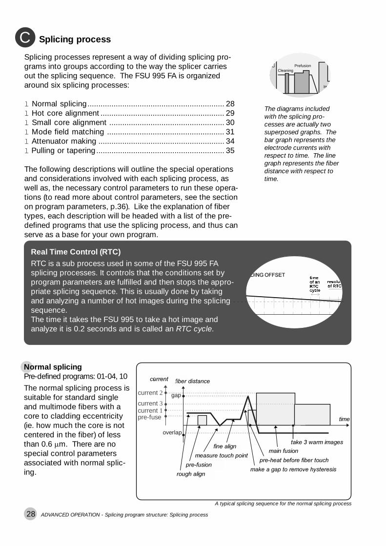
Splicing processCSplicing processes represent a way of dividing splicing pro-grams into groups according to the way the splicer carriesout the splicing sequence. The FSU 995 FA is organizedaround six splicing processes:
l Normal splicing............................................................... 28l Hot core alignment ......................................................... 29l Small core alignment ..................................................... 30l Mode field matching ...................................................... 31l Attenuator making .......................................................... 34l Pulling or tapering........................................................... 35
The following descriptions will outline the special operationsand considerations involved with each splicing process, aswell as, the necessary control parameters to run these opera-tions (to read more about control parameters, see the sectionon program parameters, p.36). Like the explanation of fibertypes, each description will be headed with a list of the pre-defined programs that use the splicing process, and thus canserve as a base for your own program.
ADVANCED OPERATION - Splicing program structure: Splicing process
Normal splicingPre-defined programs: 01-04, 10
The diagrams includedwith the splicing pro-cesses are actually twosuperposed graphs. Thebar graph represents theelectrode currents withrespect to time. The linegraph represents the fiberdistance with respect totime.
current 2
current 1current 3
pre-fuse
������� ��
gap
overlap
������ ���
��������
������ ���
����������������
����������������������������
������������������������
����������
������������������
����
�������� !"#$�$%���#!
A typical splicing sequence for the normal splicing process
The normal splicing process issuitable for standard singleand multimode fibers with acore to cladding eccentricity(ie. how much the core is notcentered in the fiber) of lessthan 0.6 �m. There are nospecial control parametersassociated with normal splic-ing.
Real Time Control (RTC) procedureRTC is a sub process used in some of the FSU 995 FAsplicing processes. It controls that the conditions set byprogram parameters are fulfilled and then stops the appro-priate splicing sequence. This is usually done by takingand analyzing a number of hot images during the splicingsequence.The time it takes the FSU 995 to take a hot image andanalyze it is 0.2 seconds and is called an RTC cycle.
Real Time Control (RTC)
',1*�2))6(7WLPHRI�DQ
F\FOH57&
UHVROXWLRI�57&
���������

29
current 2
current 1RTC cur
pre-fuse
FXUUHQW JDS
gap
overlap
URXJK�DOLJQ
SUH�IXVLRQ
PDNH�D�JDS�WR�UHPRYH�K\VWHUHVLV
SUH�KHDW�EHIRUH�ILEHU�WRXFK
UHSHDW�LI�RIIVHW�ELJ
VWRS�IXVLRQ�LI�RIIVHW���RU
�$&&(37$%/(�/,0,7
����
SUH�KHDW
WDNH�ZDUP�LPDJHV
WR�ILQG�FRUH�RIIVHW
WDNH���ZDUP�LPDJHV
FRPSXWH�FRUH�RIIVHW
ILQH�DOLJQ
PHDVXUH�WRXFK�SRLQW
$%���#!������� !"#$�
ADVANCED OPERATION - Splicing program structure: Splicing process
Hot core alignmentPre-defined program: 05
A typical splicing sequence for the hot core alignment process
The FSU 995 FA employs hot image analysis and RTC in the hot core alignment process toovercome the two main difficulties associated with highly eccentric cores. The first difficultyis that the splicer must locate the cores and align them properly. The second difficulty is thatalignment of the eccentric cores inevitably means that the claddings will not line up. Thiswould not be such a problem in and of itself if it were not for the fact that the misalignment ofthe claddings leads to surface tension during fusion that bends the fibers, and pulls the coresback out of alignment.
- FUSION CURRENT 2 is not specifically a hot core align-ment paramenter, but you should take note that if youchoose a value of 0.0 mA, the current test sets this param-eter automatically the same time it determines the RTCCURRENT. Otherwise you will have to set it manually.
&''��(&)� �� ���(
����
���������������������� ���������
�������������
������
Model of current test
Hot core alignment control parameters
ACCEPTABLE OFFSETregulates whether a RTCsequence with itscompensentory elements ora normal splicing sequencewill be used to splice thefibers. It can be that theoffset measured in the firstpart of the process is sosmall (ie. is acceptable) thatit is just as well to line up thecladdings and splice nor-mally.
RTC CURRENTis the current applied to takethe hot images needed formeasurement of the eccen-tricity of the fibers. You canset it manually, or use thecurrent test (see p. 57), whichsets it automatically.
MAX. ECCENTRICITYis used to decide whetherthe fibers should be splicedat all. To determine whetherthe maximum allowableeccentricity has beenexceded, the splicer takeshot images before splicing. Ifthis reading is above thevalue of the parameter, youwill receive a warning in themonitor, and the splicingsequence will stop.
Hot core alignment is de-signed for single mode fiberswith a core to cladding ec-centricity greater than 0.6 �m.To be able to line up andsplice fibers who are notsusceptible to the normalsplicing method of lining upthe claddings with the as-sumption that the cores willthereby also be aligned, theFSU 995 FA makes use of hotimages and real time control(RTC).
30
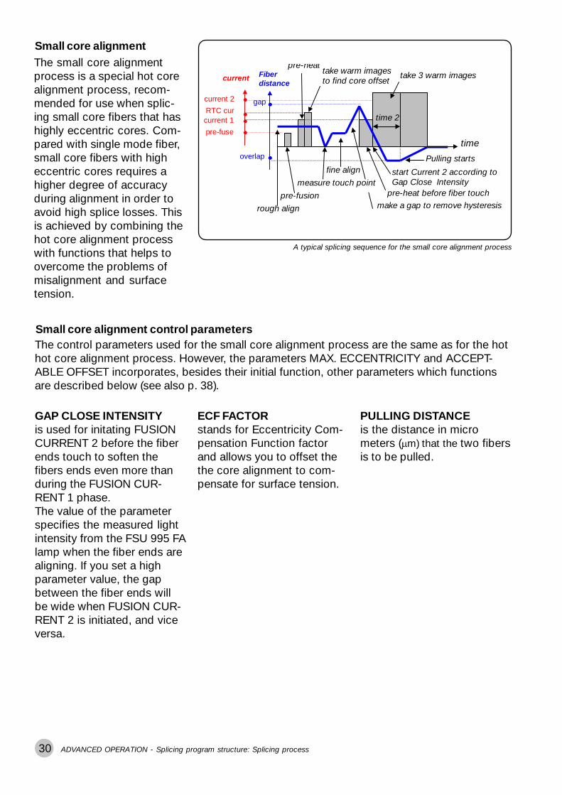
Small core alignmentThe small core alignmentprocess is a special hot corealignment process, recom-mended for use when splic-ing small core fibers that hashighly eccentric cores. Com-pared with single mode fiber,small core fibers with higheccentric cores requires ahigher degree of accuracyduring alignment in order toavoid high splice losses. Thisis achieved by combining thehot core alignment processwith functions that helps toovercome the problems ofmisalignment and surfacetension.
Small core alignment control parameters
PULLING DISTANCEis the distance in micrometers (�m) that the two fibersis to be pulled.
GAP CLOSE INTENSITYis used for initating FUSIONCURRENT 2 before the fiberends touch to soften thefibers ends even more thanduring the FUSION CUR-RENT 1 phase.The value of the parameterspecifies the measured lightintensity from the FSU 995 FAlamp when the fiber ends arealigning. If you set a highparameter value, the gapbetween the fiber ends willbe wide when FUSION CUR-RENT 2 is initiated, and viceversa.
The control parameters used for the small core alignment process are the same as for the hothot core alignment process. However, the parameters MAX. ECCENTRICITY and ACCEPT-ABLE OFFSET incorporates, besides their initial function, other parameters which functionsare described below (see also p. 38).
ECF FACTORstands for Eccentricity Com-pensation Function factorand allows you to offset thethe core alignment to com-pensate for surface tension.
current 2
current 1RTC cur
pre-fuse
current Fiberdistance
gap
overlap
rough align
pre-fusion
fine align
make a gap to remove hysteresispre-heat before fiber touch
start Current 2 according toGap Close Intensity
Pulling starts
time
pre-heattake warm imagesto find core offset
take 3 warm images
time 2
measure touch point
A typical splicing sequence for the small core alignment process
ADVANCED OPERATION - Splicing program structure: Splicing process

31ADVANCED OPERATION - Splicing program structure: Splicing process
Mode field matchingPre-defined programs: 06 & 07
A typical splicing sequence for the mode field matching process
Mode field matching control parameters
current2
current1pre-fuse
FXUUHQW JDS
gap
overlap
URXJK�DOLJQ
SUH�IXVLRQ
PDNH�D�JDS�WR�UHPRYH�K\VWHUHVLV
SUH�KHDW�EHIRUH�ILEHU�WRXFK
PDLQ�IXVLRQ
WLPH
WLPH�� WLPH��WDNH�SLFWXUHV�WR�ILQG
KRW�ILEHU�LQGLFHV
LI�LQGH[���RU�
,1'(;�/,0,7�
VWRS�DUF
......
ILQH�DOLJQ
PHDVXUH�WRXFK�SRLQW
WDNH���ZDUP
LPDJHV
�������� !"#$�
LOSS FACTORis a compensatory variableused in splice loss estimationto account for the differencebetween INDEX LIMIT (thevalue entered in the param-eter) and the measured indexafter splicing.
THRESHOLD TYPErepresents the type of com-parison that should be madebetween the hot fiber indexprofiles for the two fibers.The easiest way to set theThreshold type is by runningthe Threshold type test (seenext page).
INDEX LIMITrepresents the value the hotfiber index will be allowed toreach before the arc will shutoff, thus ending the splicingsequence. We recommendthat the first time you splicea new fiber combination thatyou run the Threshold typetest (see next page). See alsoUsing the index limit param-eter on p. 33.
The mode field matchingprocess is intended for splic-ing fibers with very dissimilarmode field diameters. That isto say: Different types of fiberrequire different diametercores to carry their fundamen-tal mode. Erbium fiber, forexample, has a smaller thanaverage core, and when youwant to splice an erbium fiberwith another type of fiber, youmust find some way to makethe transition from one core tothe other as smooth as pos-sible in order to avoid powerloss around the unmatchedcore edges. This is achievedby means of a hot fiber indexprofile. During splicing, afiber’s dopants will diffuse intoits core, decreasing its indexprofile. With two fibers thiscan result in a convergence oftheir profiles. With RTC thisprocess can be observed andthe arc stopped when the bestmatch of profiles has beenachieved.
A graph from a Threshold type test (seep.32) plotting of the index profiles for twofibers. Note how the profiles converge.

32 ADVANCED OPERATION - Splicing program structure: Splicing process
Threshold type testWhen you are presented with a new fiber combination it ishighly advisable to run the Threshold type test. You do so bysetting the parameter THRESHOLD TYPE to Threshold typetest (see page 43, for instructions as to how you edit param-eters), as well as setting up the test configuration shownbelow. During the Threshold type test, you will get an indexprofile of the two fibers based on how they behave duringheating (see picture on previous page). The result of the testwill be a value for the Index limit, as well as, the informationnecessary to choose a Threshold type. While the test isrunning, it is recommended to do a splice loss measurement,as well, which you do by pressing the #-button when the lossis at a minimum. You can save up to three data points (eg.press the #-button three times) for the splice loss measure-ment, and the final value will be their average.
Threshold types
DIFFERENCE When the difference between the two index profilesdecreases during splicing, it is possible to determine theoptimal match by just measuring the difference between thetwo index profiles, stopping the splicing sequence when thedifference is at a minimum. See also on next page.
LEFT INDEX and When the difference between the two index profiles does notRIGHT INDEX become smaller during splicing, it is necessary to measure the
absolute indexes of the fibers, rather than their difference. Youshould measure the fiber who has the least variation in itsindex profile.If the left fiber’s index varies least, choose LEFT INDEXIf the right fiber’s index varies least, choose RIGHT INDEX.
HIGHER INDEX When one fiber always has a higher index profile than theother or when the profiles cross frequently during heating, it isbest to measure the higher absolute index.
HIGHER START It is also possible to choose to measure the absolute index ofthe fiber that has the higher index in the first cycle ofmeasurement.
20 m Single fiber orDispersion shifted fiber
����������� �������������������������������������������������������������� ��������������������� ��� ��!�" #�$$��"%���&��� ��
>1 m Erbium fiber
1 2 34 5
Set-up for the threshold type test
33
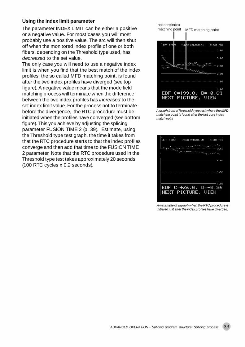
The parameter INDEX LIMIT can be either a positiveor a negative value. For most cases you will mostprobably use a positive value. The arc will then shutoff when the monitored index profile of one or bothfibers, depending on the Threshold type used, hasdecreased to the set value.The only case you will need to use a negative indexlimit is when you find that the best match of the indexprofiles, the so called MFD matching point, is foundafter the two index profiles have diverged (see topfigure). A negative value means that the mode fieldmatching process will terminate when the differencebetween the two index profiles has increased to theset index limit value. For the process not to terminatebefore the divergence, the RTC procedure must beinitiated when the profiles have converged (see bottomfigure). This you achieve by adjusting the splicingparameter FUSION TIME 2 (p. 39). Estimate, usingthe Threshold type test graph, the time it takes fromthat the RTC procedure starts to that the index profilesconverge and then add that time to the FUSION TIME2 parameter. Note that the RTC procedure used in theThreshold type test takes approximately 20 seconds(100 RTC cycles x 0.2 seconds).
Using the index limit parameter
A graph from a Threshold type test where the MFDmatching point is found after the hot core indexmatch point
MFD matching point
An example of a graph when the RTC procedure isinitiated just after the index profiles have diverged.
ADVANCED OPERATION - Splicing program structure: Splicing process
hot core indexmatching point

34 ADVANCED OPERATION - Splicing program structure: Splicing process
Attenuator makingPre-defined program: 08
A typical splicing sequence for the attenuator making process
Attenuator making is theprocess you use when youwant to reduce the strengthof a signal – because of ashort distance between atransmitter and receiver, forexample. This signalstrength reduction is, formost cases, achieved byusing RTC to measure andset a cladding offset (seediagram) to the desiredattenuation value. When thetargeted attenuation value isreached, the fibers arespliced.
������� �������� ���
gap
� �� � �������������������
������ ���������������
� ���� ���� ��
����
overlap
current 1
current 3
current 2
WDNH�D�ZDUP�LPDJH�DQGFRPSXWH�WKH�FODGGLQJ�RIIVHW�UHSHDW�LI�FODGGLQJ�RIIVHW�LVELJJHU�WKHQ�WDUJHWRIIVHW
WXUQ�RII�DUF�LI�FODGGLQJRIIVHW���RU� �WDUJHW�RIIVHW
RU�WKH�F\FOH�QXPEHUUHDFKHV�WKH�F\FOH�OLPLW
Attenuator making control parameters
ECF FACTORwhen set at a value between1 and 10, compensates forthe surface tension men-tioned in relation to hot corealignment that bends thecores out of alignment. If, onthe other hand, it is set to 0,RTC is disabled, and if setabove 10 it determines thelimit to the number of RTCcycles the splicer will carryout before ending the splic-ing sequence automatically(see above diagram).
OFFSET ADJUSTMENTis the means by which youcan adjust the target offset(the intended offset after thesplicing sequence). Thevalue you enter here will beadded to the target offsetcalculated by the splicer. Tomake the value negative, youshould use the button.
DESIRED ATTENUAT.is measured in dB, andquantifies the desired attenu-ation--the degree to whichyou want to reduce signalstrength. If you select avalue greater than 0 dB, aswell as, give the mode fielddiameters for each of thefibers in the parameters LEFTMFD and RIGHT MFD, thesplicer will automatically seta target offset for the desiredattenuation.
-
take a cold image andcompute the cladding offset:repeat if cladding offset isbigger than target offset
Note:For fibers with highly eccentric cores it is essential that the fibers are spliced with respectto the position of the cores to get a good result. To achieve this, you need to increase theparameter FUSION CURRENT 3 to 12 mA from its initial setting of 9mA. This will triggerthe attentator making process to take hot instead of cold images during the RTC proce-dure, thereby making it possible to locate the cores.

35ADVANCED OPERATION - Splicing program structure: Splicing process
Pulling or taperingPre-defined program: 09
Pulling or tapering is used primarily to create micro-lensesand microscope fiber probes out of fiber end-faces. Duringthe process, the splicer simultaneously pulls and heats thefibers into an hour glass shape that eventually divides at thetip. This tapering process increases the mode field diameterto give the fiber a higher numerical aperture. To then capital-ize on this phenomenon to make a micro-lens, the ends aremade to take on a semi-spherical form which can focus lightfrom an external source into the core.
Example of fiber probes for a micro-scope
Hour-glass form at the end of the firstpulling step using Program 09
Pulling or tapering control parameters
PULL 1, PULL 2, PULL 3are the three parameters controlling the pulling or taperingprocess. They represent three rounds of pulling, and each isassociated with the FUSION CURRENT and FUSION TIMEcarrying the same number (eg. FUSION CURRENT 2 is thecurrent used during PULL 2). The PULL parameters arebinary and can only be turned off or on.
Example of micro-lenses formed usingProgram 09
Sample program for creating fiber probes
FUSION CURRENT 1 12 mAFUSION TIME 1 15 sec.PULL 1 Yes
FUSION CURRENT 2 10 mAFUSION TIME 2 5 sec.PULL 2 Yes
FUSION CURRENT 3 7 mAFUSION TIME 3 10 sec.PULL 3 Yes

36
STANDARD FIBERNORMAL SPLICING
PREFUS TIME 0.2PREFUSE CURR 10.0GAP 50.0OVERLAP 10.0FUSION TIME 1 0.3FUSION CURR 1 10.5FUSION TIME 2 2.0FUSION CURR 2 16 3
ADVANCED OPERATION - Splicing program structure: Parameters
Program parametersDThe program parameters are the variables used by eachsplicing program to guide the splicing sequence. The FSU995 FA distinguishes three sets of program parameters: thegeneral parameters, the control parameters and the splicingparameters. The following tables will list all of these param-eters, along with their ranges of possible values and defaultvalues.
General parametersThe general parameters hold information that concerns the overall structure ofthe splicing program.
Parameter Function Range Default
PROGRAM NAME Max 16 character name All characters emptyexcept “@”
KEY NUMBER Max 3-digit security code 000 to 999 000
SECURITY TYPE 0 = Open (available to all) 0 to 2 Open (=0)1 = Read only2 = Confidential
FIBER TYPE Specifies fiber type: 0 to 5 Standard fiber0 = Standard fiber (=0)1 = Titanium fiber2 = Depress. clad. fiber3 = Erbium doped fiber4 = Invisible core fiber5 = Multimode fiber
PROCESS TYPE* Specifies splicing process: 0 to 4 Normal splicing0 = Normal splicing (=0)1 = Hot core alignment *2 = Mode field matching3 = Attenuator making4 = Pulling or tapering
Choose the Hot core alignment process if you are to use the Small core alignment process.*

37
Control parameters
The control parameters are the param-eters that control the specific operationsof each of the splicing processes, andthe following tables organizes themaccordingly.Observe that two of the control param-eters for Small core alignment, MAX.ECCENTRICITY and ACCEPTABLEOFFSET (see next page), have multiplefunctions. The figures on the right showsyou how to set these parameters.For more details on the control , you canalso refer to the preceding section onsplicing processes (p. 28-35).
ADVANCED OPERATION - Splicing program structure: Parameters
ACCEPTABLE OFFSET value 1.3
PULLING DISTANCE( 1.3 x 10 = 13 �m )
ACCEPTABLEOFFSET( 0.3 + 1.0= 1.3 )
Setting the MAX. ECCENTRICITY parameterwhen running the Small core alignment process
Parameter Function Range Default
MAX.ECCENTRICITY Max core to cladding 0.00 to 2.99 �m 1.0 �meccentricity
ACCEPTABLE OFFSET Max acceptable core offset 0.0 to 0.9 �m 0.3 �m
RTC CURRENT Heating current for inital 6.0 to 29.9 mA 11 mARTC images
INDEX LIMIT Min acceptable hot fiber index 0.0 to 9.99 0.4
THRESHOLD TYPE Comparison method for hot 0 to 5 0fiber indexes (see also p. 32)0 = Threshold type test1 = Difference2 = Left index3 = Right index4 = Higher index5 = Higher start
LOSS FACTOR Adjusts splice loss estimation 0.00 to 9.99 0.35
Hot
cor
e al
ignm
ent
Mod
e fie
ld m
atch
ing
Note that you will revoke the small core alignment process and invoke the hot core align-ment process if you set MAX. ECCENTRICITY to a value that is greater than 2.9 �m. Also, ifyou set ACCEPTABLE OFFSET to a value that is greater than 0.9 �m, you will set the PULL-ING DISTANCE parameter and thereby revoke the pulling procedure.
Continued on the following page
MAX. ECCENTRICITY value 7.3
GAP CLOSE INTENSITY( 7 = 70% )
ECF FACTOR( 0.3 + 1.0= 1.3 )
Setting the ACCEPTABLE OFFSET parameterwhen running the Small core alignment process

38
Parameter Function Range Default
DESIRED ATTENUAT. Desired level of attenuation 0.0 to 29.9 dB 0
OFFSET ADJUSTMENT User adjustment added to -29.9 to +29.9 �m 0target offset (use +/- buttons(Offset as seen in upper view) to change sign)
ECF FACTOR Surface tension compensation 00.0 to 99.0 1.5factor/ RTC control parameter*
PULL 1 Controls first round of pulling YES/NO YES (=1)
PULL 2 Controls second round of pulling YES/NO YES (=1)
PULL 3 Controls third round of pulling YES/NO YES (=1)
MAX. ECCENTRICITY 5.0 to 9.9 �m(recommended value = 7.3 )
GAP CLOSE INTENSITY 50 to 90 %Gap between fibers thatinitiates FUSION CURRENT 2
ECF FACTOR 1.0 to 1.9Surface tension compensationfactor*
MAX. ECCENTRICITY 1.0 �mMax core to cladding (unchangeable)eccentricity
ACCEPTABLE OFFSET 1.1 to 1.9 �m ( lower limit )(recommended 2.1 to 2.9 �m ( upper limit ) value = 1.3 )
PULLING DISTANCE 11 to 19 �m ( lower limit )The distance the fibers are 21 to 29 �m ( upper limit )to be pulled
ACCEPTABLE OFFSET 0.1 to 0.9 �mMax acceptable core offset
RTC CURRENT Heating current for inital 10.0 to 12.0 mA(recommended RTC imagesvalue = 11.8 )
Att
enua
tor
mak
ing
Pul
ling
or t
aper
ing
ECF = 0: RTC disabled0<ECF<1.0: Align offset = Computed offset and Target offset = ECF x computed offset1.0<ECF<10.0: Align offset = ECF x target offset where Target offset = Computed offsetECF > 10: Fixed number of RTC cycles where number of cycles = ECF - 10
Align offset = The offset the splicer sets at the beginning of the splicing sequence.Computed offset = The offset calculated by the splicer based on DESIRED ATTENUAT. and RIGHT MFD and LEFT MFD.Target offset = The intended offset at the end of the splicing sequence.
*
Sm
all
core
alig
nmen
t
ADVANCED OPERATION - Splicing program structure: Parameters

39
Splicing parameters
The splicing parameters are the parameters that control the general operations of the splicingsequence. Regardless of splicing process, the following parameters are applied to guide thesplicer through alignment, prefusion and fusion.
Nevertheless, some of these parameters are used slightly differently during particular pro-cesses. If this is the case, the parameter’s special use will be indicated in italics.
Parameter Function Range Default
PREFUSE TIME Time prefusion current runs 0.0 to 9.9 sec 0.2 sec
PREFUSE CURRENT Current during prefusion 0.0 to 29.9 mA 10.0 mA
GAP Gap set right before splicing 0.0 to 99.9 �m 50.0 �m
OVERLAP Overlap during splicing 0.0 to 49.9 �m 8.0 �m
FUSION TIME 1* Fusion time before 0.0 to 99.9 sec 0.3 secthe fiber ends touch
FUSION CURRENT 1 Fusion current before 0.0 to 29.9 mA 10.5 mAthe fiber ends touchDuring Hot core alignmentit is the initial RTC current
FUSION TIME 2 Fusion time after 0.0 to 99.9 sec 2.0 secthe fiber ends touchDuring Mode field matchingand Attenuator making it alsorepresents the waiting timebefore the RTC procedure begins.
FUSION CURRENT 2 Fusion current used from 0.0 to 29.9 mA 15.0 mAthe point the ends touchDuring Hot core alignment, ifit is set to 0, the auto-currentwill be used.
FUSION TIME 3 Relaxation time 0.0 to 99.9 sec 2.0 secDuring Hot core alignmentit is used only if the coreeccentricity is small.
FUSION CURRENT 3 Relaxation current 0.0 to 29.9 mA 12.5 mADuring Hot core alignmentit is used only if the coreeccentricity is small.
Continued on the following page
As the fiber moving speed = GAP/FUSION CURRENT 1, do not set FUSION CURRENT 1 to 0.0.*
ADVANCED OPERATION - Splicing program structure: Parameters

40
Parameter Function Range Default
ADVANCED OPERATION - Splicing program structure: Parameters
The splicing parameters listed on this page will be discussed in greater detail in the section on “Advancedsplicing parameters,” p. 55.
LEFT MFD Mode field diameter 2.0 to 19.9 �m 9.8 �mfor left fiber
RIGHT MFD Mode field diameter 2.0 to 19.9 �m 9.8 �mfor right fiber
SET CENTER Sets normal splicing or 150 to 255 pixelsoff-center splicing 360 pixels
AOA CURRENT Arc-on-alignment current 6.0 to 29.9 mA 0Disable by setting to 0.
EARLY PREFUSION Do prefusion before any YES/NO NOalignment
ALIGN ACCURACY Accuracy for axis alignment 0.01 to 9.99 �m 0.15 �m
LOSS SHIFT Adjusts the difference -1.00 to +1.00 0 dbbetween estimated andmeasured loss
AUTO ARC CENTER Activate the Automatic Arc YES/NO NORe-centering function

41
Pre-defined programs: Programs 01 - 10
As explained in the section on Basic Operation, the FSU 995FA comes with ten pre-defined programs. These programsrepresent all five splicing processes, and are intended tocover a wide array of splicing needs. It is also recommendedthat you use them as a base when designing your own pro-grams. With this in mind, the following cards list these pro-grams’ parameters. You can also see a program’s param-eters by following the instructions on page 13 for bringing upthe screen-viewer. Keep in mind, though, that these pro-grams are NOT editable. So if you want to make modifica-tions you will have to copy the program to one of the editableslots by following the instructions in the following section.
ADVANCED OPERATION - Programs 01 - 10
Program 01“NORMAL SM + SM”Standard single fiberNormal splicing
PREFUSE TIME 0.2 sPREFUSE CURRENT 10.0 mAGAP 50.0 �mOVERLAP 10.0 �mFUSION TIME 1 0.3 sFUSION CURRENT 1 10.5 mAFUSION TIME 2 2.0 sFUSION CURRENT 2 16.3 mAFUSION TIME 3 2.0 sFUSION CURRENT 3 12.5 mALEFT MFD 9.8 �mRIGHT MFD 9.8 �mSET CENTER 255AOA CURRENT 0.0 mAEARLY PREFUSION NOALIGN ACCURACY 0.15 �mLOSS SHIFT 0 dBAUTO ARC CENTER NO
P01
Program 02“DSF SM + SM”Depressed cladding fiberNormal splicing
PREFUSE TIME 0.2 sPREFUSE CURRENT 10.0 mAGAP 50.0 �mOVERLAP 8.0 �mFUSION TIME 1 0.3 sFUSION CURRENT 1 10.5 mAFUSION TIME 2 2.0 sFUSION CURRENT 2 15.0 mAFUSION TIME 3 2.0 sFUSION CURRENT 3 12.5 mALEFT MFD 9.8 �mRIGHT MFD 9.8 �mSET CENTER 255AOA CURRENT 0.0 mAEARLY PREFUSION NOALIGN ACCURACY 0.15 �mLOSS SHIFT 0 dBAUTO ARC CENTER NO
P02
Program 03“TITAN SM + SM”Titanium fiberNormal splicing
PREFUSE TIME 0.2 sPREFUSE CURRENT 10.0 mAGAP 50.0 �mOVERLAP 8.0 �mFUSION TIME 1 0.3 sFUSION CURRENT 1 10.5 mAFUSION TIME 2 2.0 sFUSION CURRENT 2 14.0 mAFUSION TIME 3 2.0 sFUSION CURRENT 3 13.0 mALEFT MFD 9.0 �mRIGHT MFD 9.0 �mSET CENTER 255AOA CURRENT 6.5 mAEARLY PREFUSION YESALIGN ACCURACY NOLOSS SHIFT 0 dBAUTO ARC CENTER NO
P03
Program 04“NORMAL MM + MM”Multimode fiberNormal splicing
PREFUSE TIME 0.3 sPREFUSE CURRENT 11.5 mAGAP 50.0 �mOVERLAP 12.0 �mFUSION TIME 1 0.3 sFUSION CURRENT 1 12.0 mAFUSION TIME 2 2.0 s
FUSION CURRENT 2 15.5 mAFUSION TIME 3 1.0 sFUSION CURRENT 3 12.5 mALEFT MFD 9.8 �mRIGHT MFD 9.8 �mSET CENTER 255AOA CURRENT 0.0 mAEARLY PREFUSION NOALIGN ACCURACY 0.25 �mLOSS SHIFT 0 dBAUTO ARC CENTER NO
P0
4

42 ADVANCED OPERATION - Programs 01 - 10
Program 05“ECCENTRIC SM + SM”Single fiber with eccentric coreHot core alignment
MAX ECCENTRICITY 1.0 �mRTC CURRENT 12.5 mAACCEPTABLE OFFSET 0.3 �mPREFUSE TIME 0.3 sPREFUSE CURRENT 10.0 mAGAP 50.0 �mOVERLAP 8.0 �mFUSION TIME 1 0.2 sFUSION CURRENT 1 10.5 mAFUSION TIME 2 0.3 sFUSION CURRENT 2 0.0 mAFUSION TIME 3 3.0 sFUSION CURRENT 3 16.0 mALEFT MFD 9.8 �mRIGHT MFD 9.8 �mSET CENTER 255AOA CURRENT 0.0 mAEARLY PREFUSION NOALIGN ACCURACY 0.10 �mLOSS SHIFT 0 dBAUTO ARC CENTER NO
P05Program 09“SM FIBER LENS”Standard single fiberPulling or tapering
PULL 1 YESPULL 2 YESPULL 3 YESPREFUSE TIME 0.3 sPREFUSE CURRENT 10.0 mAGAP 0.0 �mOVERLAP 0.0 �mFUSION TIME 1 9.0 sFUSION CURRENT 1 15.0 mAFUSION TIME 2 7.0 sFUSION CURRENT 2 12.0 mAFUSION TIME 3 2.0 sFUSION CURRENT 3 7.0 mALEFT MFD 9.8 �mRIGHT MFD 9.8 �mSET CENTER POSITION 255AOA CURRENT 0.0 mAEARLY PREFUSION NOALIGN ACCURACY 0.15 �mLOSS SHIFT 0 dBAUTO ARC CENTER NO
P09
Program 06“ERBIUM + SM MCVD”Erbium fiber with single fiberMode field matching
INDEX LIMIT 0.4THRESHOLD TYPE DifferenceLOSS FACTOR 0.35PREFUSE TIME 0.3 sPREFUSE CURRENT 10.0 mAGAP 50.0 �mOVERLAP 8.0 �mFUSION TIME 1 0.3 sFUSION CURRENT 1 10.5 mAFUSION TIME 2 2.0 sFUSION CURRENT 2 15.5 mAFUSION TIME 3 0.5 sFUSION CURRENT 3 12.0 mALEFT MFD 7.5 �mRIGHT MFD 8.5 �mSET CENTER POSITION 255AOA CURRENT 6.5 mAEARLY PREFUSION NOALIGN ACCURACY 0.10 �mLOSS SHIFT 0 dBAUTO ARC CENTER NO
P06
Program 07“ERBIUM + DSF OVD”Erbium with dispersion shiftedMode field matching
INDEX LIMIT 2.6THRESHOLD TYPE Higher startLOSS FACTOR 0.35PREFUSE TIME 0.3 sPREFUSE CURRENT 10.0 mAGAP 50.0 �mOVERLAP 4.0 �mFUSION TIME 1 0.3 sFUSION CURRENT 1 10.5 mAFUSION TIME 2 1.5 sFUSION CURRENT 2 15.0 mAFUSION TIME 3 0.5 sFUSION CURRENT 3 12.0 mALEFT MFD 7.5 �mRIGHT MFD 9.0 �mSET CENTER POSITION 255AOA CURRENT 6.5 mAEARLY PREFUSION YESALIGN ACCURACY 0.10 �mLOSS SHIFT 0 dBAUTO ARC CENTER NO
P07Program 08“SM ATTENUATOR”Standard single fiberAttenuator making
DESIRED ATTENUAT. 15 dBOFFSET ADJUSTMENT 0.0 �mECF FACTOR 1.3PREFUSE TIME 0.3 sPREFUSE CURRENT 10.0 mAGAP 50.0 �mOVERLAP 4.0 �mFUSION TIME 1 0.3 sFUSION CURRENT 1 10.0 mAFUSION TIME 2 0.6 sFUSION CURRENT 2 12.0 mAFUSION TIME 3 0.3 sFUSION CURRENT 3 9.0 mALEFT MFD 9.8 �mRIGHT MFD 9.8 �mSET CENTER POSITION 255AOA CURRENT 6.5 mAEARLY PREFUSION NOALIGN ACCURACY 0.10 �mLOSS SHIFT 0 dBAUTO ARC CENTER NO
P08
Program 10“SM 80 UM MICRON”Standard single fiberNormal splicing
PREFUSE TIME 0.2 sPREFUSE CURRENT 8.0 mAGAP 40.0 �mOVERLAP 4.0 �mFUSION TIME 1 0.3 sFUSION CURRENT 1 8.5 mAFUSION TIME 2 2.0 sFUSION CURRENT 2 12.0 mAFUSION TIME 3 0.0 sFUSION CURRENT 3 0.0 mALEFT MFD 8.5 �mRIGHT MFD 8.5 �mSET CENTER POSITION 255AOA CURRENT 0.0 mAEARLY PREFUSION NOALIGN ACCURACY 0.10 �mLOSS SHIFT 0 dBAUTO ARC CENTER NO
P10
43
Program editing: Programs 11 - 50
Choose a program to edit1
Start program selection
NEW PROGRAM?“
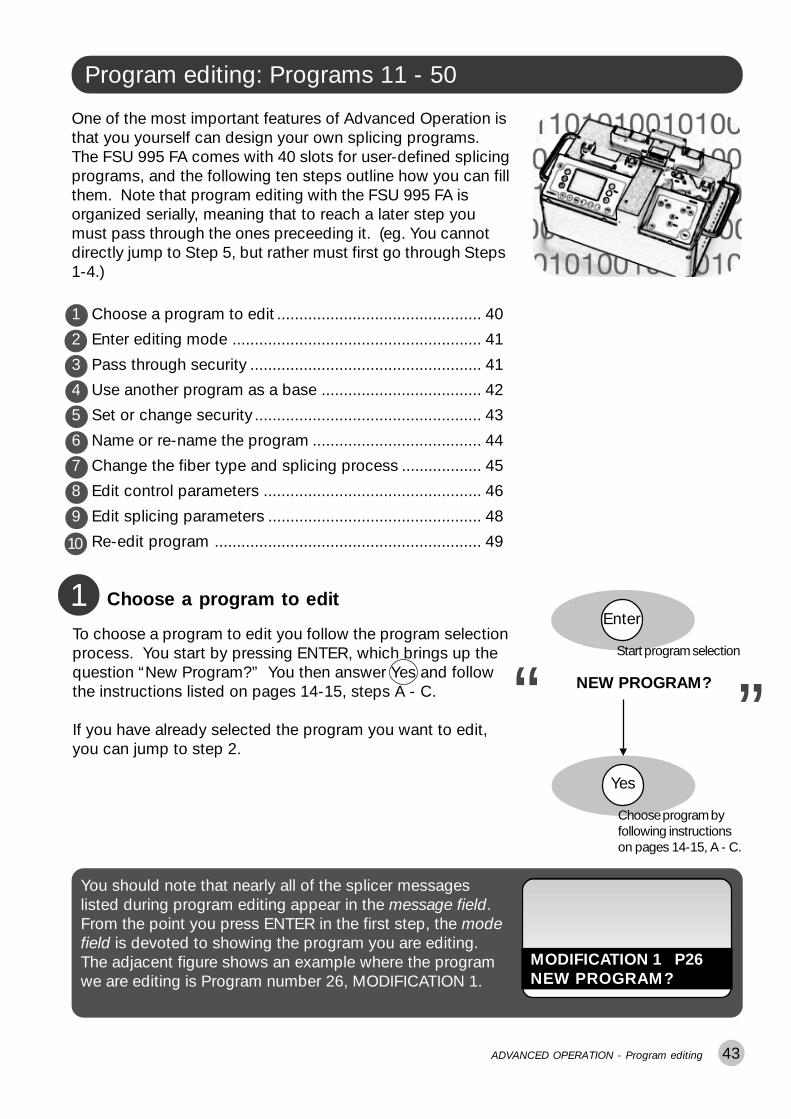
“To choose a program to edit you follow the program selectionprocess. You start by pressing ENTER, which brings up thequestion “New Program?” You then answer Yes and followthe instructions listed on pages 14-15, steps A - C.
If you have already selected the program you want to edit,you can jump to step 2.
Yes
Choose program byfollowing instructionson pages 14-15, A - C.
Enter
ADVANCED OPERATION - Program editing
You should note that nearly all of the splicer messageslisted during program editing appear in the message field.From the point you press ENTER in the first step, the modefield is devoted to showing the program you are editing.The adjacent figure shows an example where the programwe are editing is Program number 26, MODIFICATION 1.
MODIFICATION 1 P26NEW PROGRAM?
One of the most important features of Advanced Operation isthat you yourself can design your own splicing programs.The FSU 995 FA comes with 40 slots for user-defined splicingprograms, and the following ten steps outline how you can fillthem. Note that program editing with the FSU 995 FA isorganized serially, meaning that to reach a later step youmust pass through the ones preceeding it. (eg. You cannotdirectly jump to Step 5, but rather must first go through Steps1-4.)
1 Choose a program to edit .............................................. 40
2 Enter editing mode ........................................................ 41
3 Pass through security .................................................... 41
4 Use another program as a base .................................... 42
5 Set or change security ................................................... 43
6 Name or re-name the program ...................................... 44
7 Change the fiber type and splicing process .................. 45
8 Edit control parameters ................................................. 46
9 Edit splicing parameters ................................................ 48
Re-edit program ............................................................ 4910

44
Enter editing mode2Enter
Start program editing
NEW PROGRAM?“
“Regardless of whether you have just gone through the pro-gram selection procedure, or are starting program editinghere, you press ENTER to enter editing mode. (It is equiva-lent to step D in the program selection procedure.) Thesplicer will then ask you (possibly for the second time) if youwant to change program.
If the program listed in the mode field is indeed the one youwant to edit, you should answer No , and reject programselection.
No
Reject program selection
Program to edit in mode field
Yes
Confirm editing
EDIT PARAMETERS?“
“
The splicer will then ask if you want to edit parameters, andyou confirm this by pressing Yes . At this point you will enterprogram editing mode.
If you answer No, you will exit both program editing andprogram selection, and will return to splicing mode.
Pass through security3If the program you have selected in step 1 is classified as an“Open” program, you will not be asked to enter a key number(a security code).
If, however, the selected program is classified as either “Readonly” or “Confidential,” you must enter the security code atthis point using the number buttons. Remember that thenumber buttons are organized such that the first button (fromthe left) corresponds to the first number of the code, thesecond button to the second number, and the third to thethird.You will then have to confirm the code by pressing ENTER. Ifyou have entered the wrong code, you will be aborted fromprogram editing.
KEY NUMBER xx.x““
0-9 0-9 0-9
Type in security code
Enter
Enter code
ADVANCED OPERATION - Program editing

45ADVANCED OPERATION - Program editing
OVERWRITE Pxx ?““
Confirm wish to over-write parameters
Yes
The splicer will then ask you to confirm that you want to re-place the parameters in the program selected in step 1 withthose of the source program just selected. This confirmationis very similar to what computers do when they ask you if youare sure you want to delete a certain file, because copying thesource program’s parameters will erase whatever parameterswere there beforehand.
To confirm your desire to copy the source program, press Yes .If you press No, then the copying will be cancelled.
As a last precaution, the splicer will then ask for the securitycode for the source program if the source program is classi-fied as “Confidential”. This is to ensure that no one has ac-cess to programs they shouldn’t just by copying them to anew slot. To give a source program’s security code, you followthe same procedure as in step 3.
Pass through securityon source program
See step 3
Use another program as a base4As has been recommended earlier, it is helpful to use anotherprogram as a base when designing your own. If you want todo so, and copy the parameters of another program into theslots of your new program, you should press Yes at this point.If you do not want to copy parameters from another program--because you are editing again a program you designedpreviously, for example--you should press No and go ontostep 5 on the following page.
The splicer will then ask in the message field which programyou want to copy (“Copy Source Pyy”), and you must enterthe number of the program you want to copy by using thefirst two number buttons (from the left). Let’s say that wechose to copy the parameters from Program 08. In that caseyou would enter a “0” with the first number button and an “8”with the second.
You enter the choice of source program by pressing ENTER.
COPY PARAMETERS?“
“
0-9 0-9
Type in source programnumber
Confirm wish to copy
COPY SOURCE Pyy“
“
Enter
Enter source program
Yes

46
0-9 0-9 0-9
ADVANCED OPERATION - Program editing
Set or change security5Before you start creating or editing your program it is impor-tant to stop and determine what type of security you want onit. If, for example, you just copied the parameters out of oneof the pre-defined programs, the security is classified as“Open,” meaning that anyone could come along after youand change the parameters again. If you don’t want this tohappen, you can protect your program by making it either“Read only” or “Confidential.”
A The first step in changing security is to change the securitycode. If you are intending that the program have a securitytype other than “Open,” it is necessary to have a code knownonly by those who need access to the program’s parameters.Remember that the security code imported from pre-definedprograms is “00.0,” and is printed in the manual.To confirm that you want to change the security code, press Yes .
The message field will then open up for you to enter a newcode by displaying “New code xx.x.” You can then type inyour new code using the number buttons. As always withsecurity codes, it is best to pick something memorable butnot too obvious.
You enter your new security code by pressing ENTER.
B It is now time to change the security type--to choosewhether the program will be classified as “Open,” “Readonly” or “Confidential.” The splicer will ask in the messagefield “Change security type”?, and to do so, press Yes.If you press No, you go to step 6.
The splicer will then present each possibility one by one. Itwill first read “Open?!” in the message field, and if you do notwant the program to be classified as Open you press No. Itwill then offer “Read Only?” as an alternative, and after that“Confidential?” If you press No when it reads “Confidential?”“Open?!” will come up again.
In short, you scroll through this list with the No button untilthe security type you want is shown in the message field, andthen press Yes.
CHANGE SECURITY?“
“
To change security onnew program
Yes
CHANGE SECURITY CODE“
“
Confirm wish to changesecurity code
Yes
NEW CODE xx.x“
“
Type in new code
Enter
Enter new security code
CHANGE SECURITY TYPE“
“
To change security type
Yes
OPEN?!No
READ ONLY?No
CONFIDENTIAL?
“ “
Choose security type
Yes

47
FSU 975
GapFuse
RightLeft
Up
Down
Name or re-name the program6CHANGE PROGRAM NAME?“
“
Confirm wish to name
Enter
Enter program name
Yes
The next step is to name--or re-name, in the case of simpleediting--the splicing program. As explained above, the pro-gram name will be stored, with the security code and securitytype, amongst the general program parameters. The splicerwill ask in the message field, “Change program name?,” andto do so, you press Yes .
To orient yourself within the splicing program structure, youshould take note that the step we just completed was tochange two of the general parameters listed on page 36:KEY NUMBER and SECURITY TYPE. The other threegeneral parameters (PROGRAM NAME, FIBER PROCESS,and FIBER TYPE) are changed in the following steps,steps 6 and 7.
General parameters
The general parameters ho
Parameter
PROGRAM NAME
Entering text on the FSU 995FA is controlled by the arrowbuttons, according to theadjacent description. Youcan also use a method ofquick character selection,which is described on page61 to facilitate the process.Regardless how you enterthe name, it should be nomore than 16 characterslong, and sufficiently specificthat you will recognize itquickly and easily.
The left arrow buttonscontrol the cursor position,moving the cursor forwardor backward one letter at atime.
The right arrow buttonsmove the cursor to the
beginning or end of a line.
The up and down arrowscontrol characterselection, changing theletter of the currentcursor position forwardor backward through thealphabet.
When you have successfully typed in the new program name,you press ENTER to save it.
ADVANCED OPERATION - Program editing

48 ADVANCED OPERATION - Program editing
Change fiber type and splicing process7CHANGE FIBER/PROCESS“
“
Open screen-viewer
View
At this point the splicer will ask if you want to change fibertype and/or splicing process. If you have copied over asource program (step 4) for which you only want to modify afew parameters, you may be able to skip this step. However,this is also a chance to verify that the right fiber type andsplicing process are specified. To see these parameters youcan press VIEW and bring up the screen-viewer. The fibertype and splicing process will be highlighted.
If you wish to change fiber type and/or splicing process,press Yes.
If you do not, press No and go on to Step 8.
A The splicer will start with fiber type and ask you whetheryou want to change it by displaying “Change fiber type?” inthe message field. If you are interested in changing the fibertype, press Yes.
If you are only interested in changing the splicing process,press No, and continue reading at “B” on the next page.
The splicer will then present you the options for fiber type inthe same format as it did with security types: Each fiber typewill successively be shown in the message field, while youscroll through them by pressing No.
When the fiber type you want is shown in the message field,you press Yes.
������������ ��� ������������� ���� � ! � "��� ��
�� #$ �$���%��#&�� '���'���#!
Screen-viewer with fiber type and splicingprocess highlighted
Affirm wish to changefiber type and/or process
Yes
CHANGE FIBER TYPE?““
To change fiber type
Yes
“
“
Choose fiber type
Yes
STANDARD FIBER?!No
TITANIUM FIBER?No
DEPRESS. CLAD. FIBERNo
ERBIUM FIBER?No
INVISIBLE CORE FIBER?No
MULTIMODE FIBER?
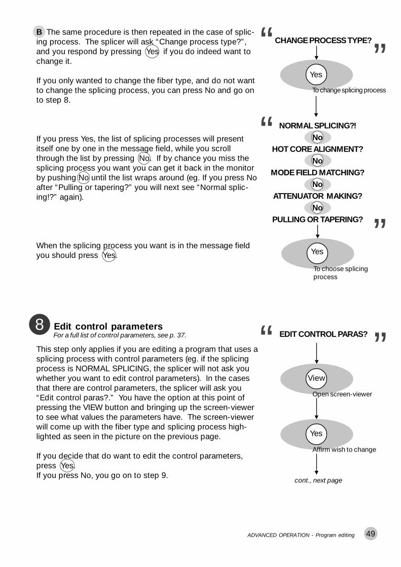
49
CHANGE PROCESS TYPE?“
“
To change splicing process
Yes
“
“
To choose splicingprocess
Yes
NORMAL SPLICING?!No
HOT CORE ALIGNMENT?No
MODE FIELD MATCHING?No
ATTENUATOR MAKING?No
PULLING OR TAPERING?
B The same procedure is then repeated in the case of splic-ing process. The splicer will ask “Change process type?”,and you respond by pressing Yes if you do indeed want tochange it.
If you only wanted to change the fiber type, and do not wantto change the splicing process, you can press No and go onto step 8.
If you press Yes, the list of splicing processes will presentitself one by one in the message field, while you scrollthrough the list by pressing No. If by chance you miss thesplicing process you want you can get it back in the monitorby pushing No until the list wraps around (eg. If you press Noafter “Pulling or tapering?” you will next see “Normal splic-ing!?” again).
When the splicing process you want is in the message fieldyou should press Yes.
ADVANCED OPERATION - Program editing
“
Edit control parameters8EDIT CONTROL PARAS?“
Open screen-viewer
View
This step only applies if you are editing a program that uses asplicing process with control parameters (eg. if the splicingprocess is NORMAL SPLICING, the splicer will not ask youwhether you want to edit control parameters). In the casesthat there are control parameters, the splicer will ask you“Edit control paras?.” You have the option at this point ofpressing the VIEW button and bringing up the screen-viewerto see what values the parameters have. The screen-viewerwill come up with the fiber type and splicing process high-lighted as seen in the picture on the previous page.
If you decide that do want to edit the control parameters,press Yes.If you press No, you go on to step 9.
Affirm wish to change
Yes
cont., next page
For a full list of control parameters, see p. 37.

50 ADVANCED OPERATION - Program editing
INDEX LIMIT 0.4“
“
Step-by-step:In the adjacent example, you will first see “Index limit” with itspresent value, which you can change by pressing the firsttwo numerical buttons (from the left) until the desired value isdisplayed. You then press ENTER.
The next control parameter is Threshold type, which will bepresented to you in the form of a list of all the possible val-ues. You scroll through this list by pressing No, until thedesired value is displayed. You then press Yes.
The last mode field matching parameter is LOSS FACTOR,which will appear in the message field along with its presentvalue. You enter a new value, if desired, with the numericalbuttons, and then press ENTER.
0-9 0-9
Type in new value
Enter
Enter value
““
Choose Threshold type
Yes
TYPE: THRESHOLD TESTNo
TYPE: DIFFERENCENo
TYPE: LEFT INDEXNo
TYPE: RIGHT INDEXNo
TYPE: HIGHER INDEXNo
TYPE: HIGHER START
As all splicing processes have different control parameters (seepages 28-35), we will take the control parameters for mode fieldmatching as an example. The range for possible values formode field matching control parameters is listed on p. 37.
Cont. from preceding page
The following example is for aprogram using mode field matching:
LOSS FACTOR 0.35“
“
0-9 0-9
Type in new value
Enter
Enter value
0-9You should note that the procedure for editing controlparameters has a logic that applies to all parameter edit-ing, so once you are used to the logic for control param-eter editing, you will know how to change any FSU 995 FAparameter (see also p. 53 for a review of this logic).
In short:Each of the parameters appears successively in the messagefield, and you first change its value with either the numberbuttons, in the case of quantitative parameters, or Yes andNo buttons, in the case of a binary (On/Off) parameters, andthen press ENTER to save the new value. The only excep-tions are parameters, such as Threshold type test, whichhave several distinct, non-numerical values. These param-eters will present themselves as fiber type and splicing pro-cess do.
In the example shown to the right, the values you canchange are highlighted. However, they will not be high-lighted in the message field of the splicer.

51
Edit splicing parameters9 EDIT SPLICING PARAS?“Open screen-viewer
View
If you have just edited control parameters, this step will bevery straight-forward. First, the splicer will ask you “Editsplicing paras?,” and once again you have the option ofpressing the VIEW button to bring up the screen-viewer. Ifopened, the screen-viewer will come up with the splicingparameters highlighted.
Next, if you want to edit the splicing parameters, press Yes.If you press No, you go on to step 10.
Affirm wish to change
Yes
PREFUSE TIME 0.3 S
“
Step-by-step:After you press Yes, the first splicing parameter, PREFUSETIME, will appear in the message field along with its currentvalue. If you want to change it, you use the number buttonsto change it. When you have the desired value for the pa-rameter, press ENTER.
The splicer will then display the second parameter, PREFUSECURR, and its value, which you can also change using thenumber buttons. Save the new value by pressing ENTER.
The rest of the parameters will follow this exact same proce-dure, with the exception of EARLY PREFUSION. For anexample of how to deal with such binary parameters, see theparameter editing summary on page 53.
Splicing parameter editing is complete when the value forthe last parameter has been entered.
0-9 0-9
Type in new value
Enter value
For those of you who skipped over control parameterediting, we want to once again point out that the proce-dure for editing splicing parameters has a logic that ap-plies to all parameter editing. So once you are used to thelogic for splicing parameter editing, you will know how tochange any FSU 995 FA parameter (see also p. 53 for areview of this logic).
Enter
“
“
PREFUSE CURR 10.0 MA
“
0-9 0-9
Type in new value
Enter value
“0-9
.......other parametersfollow same procedure
Enter finalparameter value
Enter
Enter
ADVANCED OPERATION - Program editing
In short:Each of the parameters appears successively in the messagefield, and you first change its value with either the numberbuttons, in the case of quantitative parameters, or Yes andNo buttons, in the case of a binary (On/Off) parameters, andthen press ENTER to save the new value.
For a full list of splicing parameters, see p. 39.
In the example shown to the right, the values you canchange are highlighted. However, they will not be high-lighted in the message field of the splicer.

52
Re-edit program10 RE-EDIT PROGRAM?“Get screen-viewer
View
At this point you have finished editing the splicing program.The splicer gives you a chance to go back, however, andmake adjustments you might have missed the first timeround.
If you are not sure about whether you are satisfied with thecurrent version of the program, you should press VIEW andbring up the screen-viewer. The screen-viewer will give you alist of all parameters (control and splicing) and their values.
If you are satisifed with the program, press No and end theediting session. The splicer will tell you it is “Updating pa-rameters...” and then return to splicing mode.
If you press Yes, you will return to step 5 (p. 46).
End editing session
No
“
UPDATING PARAMETERS...“
“
ADVANCED OPERATION - Program editing
Once you have gone through the program editing se-quence once or twice, you will probably no longer needthe step-by-step guide presented on these pages. Never-theless, you may still want some reference for locatingspecific parameters and keeping tabs on where you are inthe overall editing tree. If this is the case, you can look atthe program editing flow chart in Appendix C, p. 77 .
Change security code?
YN
New code xx.x

53ADVANCED OPERATION - Parameter editing review
Parameter editing review
When considered step by step parameter editing can seeminterminable; however, there is a basic logic that guides theediting procedure. Once you have become familiar with thislogic, parameter editing will go easily and quickly.
The programming buttons
EnterThe ENTER button has two functions:1. To initialize the editing procedure.2. To enter new values for the parameters.
ViewThe VIEW button brings up the screen-viewer, so you cancheck the current values for parameters.
YesThe YES button is used to answer two sorts of questions:1. In navigation through a procedure, to answer that you wantto make the changes involved in the next step.2. With binary parameter values (see description on thefollowing page), to turn a parameter ON.
NoThe NO button is used to answer two sorts of questions:1. In navigation, to answer that you do NOT want to make thechanges involved in the next step. It is by pushing the NObutton that you accelerate yourself from step to step duringthe editing procedure.2. With binary parameter values (see description on thefollowing page), to turn a parameter OFF.
0-9 0-9 0-9
The number buttons are used to enter numerical values forquantitative parameters.
Navigation through the parameter editing procedure
Navigation during parameter editing occurs by means of Yes/No questions. The editing procedure has been designed inblocks. The steps 1-10 you have just gone through corre-spond to these blocks. If you notice each of these blocks isprefaced by a Yes/No question. If you answer Yes, you gothrough the step and carry out the changes it entails. If youanswer No, you jump to the next step. This makes it possibleto speed up the editing procedure if you know in advancewhat you want to change.
9876

54
Types of parameter valuesParameters can be divided according to the kind of valuesthey hold. In the FSU 995 FA there are three major types ofparameter values, each of which involves a slightly differentediting procedure.
1 Quantitative parameter valuesA quantitative parameter value is a number. An example isfound in PREFUSE TIME, which we saw edited on page 51.The general procedure is as follows:- The parameter appears with its current value.- You can change the value using the number buttons- You press ENTER to save the new value.
2 Binary parameter valuesA binary parameter value has two states, usually either ON orOFF. An example of this type of value amongst the splicingparameters is EARLY PREFUSION, which we will take as anexample here:- The parameter name is presented as a question, and avariable region which toggles between Yes and No.- Press the No button to turn the parameter off, and the Yesbutton to turn it back on again.- Press ENTER to save the value of the parameter.
3 Parameters with multiple valuesThere are a few parameters which have multiple, non-numeri-cal values. An example amongst the general parameters isSECURITY TYPE, which we saw edited on page 46. Thegeneral procedure is as follows:- The first possible value for the parameter occurs with aquestion mark.- If this is not the value you want, you press No, at whichpoint the second value appears, again as a question.- You continue to press No and scroll through the list ofpossible values until the value you want is shown in themessage field. At which point you press Yes and enter thenew value for the parameter.
EARLY PREFUSION ON YES
Toggle on/off
Enter value
Enter
“
“
PREFUSE TIME 0.3 S“
“
See example page 51
No Yes
OPEN?!No
READ ONLY?No
CONFIDENTIAL?
“ “
See example page 46
ADVANCED OPERATION - Parameter editing review

55
Special functions
ADVANCED OPERATION - Special functions: Advanced splicing parameters
Advanced splicing parametersAMode field diameters: LEFT MFD and RIGHT MFDIn order to obtain good spliceloss estimation it is importantto correctly set the mode fielddiameters for your fibers. Themode field diameters are listedin the specifications for fibers,and the adjacent table givessome representational values.Nevertheless, if possible, it isalso a good idea to test yourfibers by comparing measuredand estimated splice lossesover a series of splices.
Fiber Type 488 633 850 980/1060 1300 1550
Single mode 3.7 4.3 5.7 6.6 9.3 10.5
High NASingle mode - 3.3 4.3 5.3 6.6 7.8
DispersionShifted - - - - - 8.1
Wavelength (nm)
MFD
(�m
)
Arc offset: SET CENTER POSITION
The SET CENTER POSITION parameterallows you to distribute different energylevels to left and right fiber during splicing.This is useful when splicing two differentkinds of fibers requiring differenttemperatures for melting.The value of the parameter represents thenumber of pixels from the left to the right endof the monitor, from 0 to 510 pixels, and theposition where you want the fiber ends tosplice. The default value is 255 pixels. This isin the absolute center of the monitor and theposition where the energy, or heat, from thearc is at its maximum. If you use a lowervalue than 255, the right fiber will thereforehave a higher temperature than the left, andthe opposite, if the value is set higher.
Note that the two global parameters GLOBAL XCT and AUTOXCT OFFSET also affects theposition where the fiber ends will splice, that is, the splicing position. The following formulashows how to calculate the splicing position for the forthcoming splice:
Splicing position = GLOBAL XCT + (SET CENTER POSITION -255) + AUTOXCT OFFSET
Setting the SET CENTER POSITION parameter
0 pixels
Electrode
Fiber
510 pixels
Electromagneticfield
Monitorarea

56 ADVANCED OPERATION - Special functions: Advanced splicing parameters
Prefusion before alignment: EARLY PREFUSIONThe parameter EARLY PREFUSION is specifically designedfor the problems associated with carbon coated fibers. Thecarbon coating has a tendency to give off more materialduring arc ignition, and thus cause more build-up on theelectrodes. To avoid this, you can set EARLY PREFUSION toON, and the prefusion will occurs before the fibers arebrought close to the electrodes during alignment.
Alignment accuracy: ALIGN ACCURACYAlignment is executed with the degree of accuracy specified in this parameter. There may becases, however, where the splicing combination demands, or allows for, a greater, or lesser,degree of accuracy than the default of 0.15 �m. You should keep in mind, though thatincreased accuracy is paid for in terms of the increased time it takes for the splicer to alignthe fibers.
Arc-on alignment: AOA CURRENTAt arc ignition an electromagnetic field is estab-lished that exerts force on the fibers, bendingthem out of alignment (see adjacent picture).After initial ignition, the force disappears, andmost fibers comes back into place. However,carbon coated and small core fibers are pulledto a significantly different degree than otherfiber types , so with these fibers, it is particularlylikely that the fibers will lose their alignment atarc ignition. To compensate for this problem, theFSU 995 FA is equipped with the option of set-ting a low current that can be ignited during finealignment. This ensures that the alignment is
carbon coating
electrode
force at igniting
very low current (6 mA)
Increased force because of the conductivity ofcarbon coating
Splice loss calibration: LOSS SHIFT
Use the parameter LOSS SHIFT to calibrate the FSU995 when there is a consistent mismatchbetween measured and estimated splice loss. Set the parameter to a value that reflects theaverage difference between the measured loss, shown on the external measuring equipment,and the estimated loss, calculated by the FSU 995.
Increased build-up on electrodes fromcarbon coated fiber
done according to the position that the fiberswill be in during splicing. The default value of the AOA CURRENT parameter is 6.5 mA, and itis important not to deviate too far from the default value. Too high of a current will lead tomatchsticking. Too low of a current can permanently damage the electrical equipment insuch a way that the arc won’t be able to ignite.
Automatic arc re-centering : AUTO ARC CENTERAutomatic Arc Re-centering is an automatic function that prevents high splice losses causedby uneven distribution of energy between left and right fibre during arc ignition. The reasonfor the uneven energy distribution is that material from the fibres are deposited on the elec-trodes when splicing, changing the electromagnetic field of the arc. This may, as a result,cause high splice losses. To avoid this to happen, the splicing position is automatically ad-justed, before every splice, with an offset to compensate for the predicted arc change. It isthis offset that is displayed in the parameter AUTOXCT OFFSET (p.62).

57
######## ####
ADVANCED OPERATION - Special functions: Service functions
Service functions: #-buttonBIf you press the #-button while in splicing mode you gainaccess to yet another group of operations and parameters.The following section outlines them in the order they come upduring editing. However, if you want a more precise overviewof the organization of these parameters, see the flow chart inAppendix C.
Current test for hot core alignment: CURRENT TEST?
If you have chosen a program with hot core alignment as its process, the first question thatwill come up when you press the button is whether you want to run the current test. Thecurrent test is used to set the RTC CURRENT parameter, which is described on page 29. Thefollowing outlines the procedure you must follow if you want to run the current test and storethe resulting value in a hot core alignment program.
#
1 Choose a program that uses the hot core alignment pro-cess. Note that, though you can run the current test with thepre-defined program 05, the resulting value can not be storedin it, so it is best to copy it to another slot by following theinstructions on page 45.
2 Press the button.
3 Press the Yes button to say you want to run the currenttest. You will subsequently have to answer No three times, inorder to reject the other operations available via the #-butto--namely “Clean electrodes?” “Splicelist handling?” and “Enterservice mode?”
4 The splicer will then instruct you that in order to start thecurrent test, you must press the FUSE button.
5 The splicer will then run the current test, store the valuefor RTC CURRENT, and carry out the splicing sequence to itscompletion. If the splicer can not splice the tested fibers(because they became damaged during the test), it will dis-play the fault message “REPLACE FIBERS,” and you willhave to replace the fibers before splicing. If you run the testusing Program 05, the splicer can not save a value for RTCCURRENT and will display “CHANGES NOT SAVED.”
������������� � � ���������� �� � ������������������� � � ��
����������������������������
Example of a program with hot core alignmentin the screen-viewer. The parameter valueshave been copied from P05 into a new slot
and the program renamed.
# #To access current test
Yes
““
CURRENT TEST?
Choose current test
No No No
Reject other operations
Run current test
Fuse
“
“
TESTING CURRENT...
○
○
“
“
SPLICING...
○
○

58 ADVANCED OPERATION - Special functions: Service functions
Electrode cleaning program: CLEAN ELECTRODES?
If you press the button, and you do not have a hot corealignment program in memory, the first question will be askedis whether you want to “Clean electrodes?”. This is some-thing that should be done every time you brush off or replacethe electrodes, and is a recommended measure after everytwenty splices. If you want to run the cleaning program press Yes. To then start the cleaning program, press FUSE. Torepeat the program (which is recommended), press FUSEagain when the program ends. When done cleaning theelectrodes, restart the splicer by pressing ON/OFF twice.
#
Splice-list handling
If you press the button, and reply No to the question ofwhether you want to clean the electrodes, you will gain ac-cess to splice-list handling. The splice-list handling proce-dure occurs in three stages.
#
Magnified electrode tip with deposits
1 Turn on splice-list handlingYou first must turn splice-list handling on by turning on thebinary parameter SPLICE LIST:
#-button > “Clean electrodes?” > NO > “Splicelist handling?” >YES >“Change list On/Off” > YES > “Splice list On.” If necessary, pressYes again, so the parameter reads “Splice list On Yes.”
Then press ENTER.
The splicer will then give you the opportunity of setting threeorganizational parameters by asking “Change list codes?”
If you say Yes, you will have a chance to specify codes thatcan be used to organize your splicing data.
Enter
“
“
SPLICE LIST ON YES
Turn on splice-list
““
CHANGE LIST CODES?
Yes
To access list codes
Enter“
“
OPERATOR NBR 00OPERATOR NBR is intended to specify who it is that is creat-ing the splicing data. It can be changed during data collec-tion, so that operators can be compared. You must assignthe numbers yourself.
Enter“
“
LIST CODE 1 00LIST CODE 1 is the first two entirely open areas where youcan tag data with additional information that might be impor-tant for later analysis. An example might be if you want tohave a set of codes for different splicing sites.
Enter“
“
LIST CODE 2 00LIST CODE 2 is the second of the two user-definable datatags. Remember that the coding system is your own, andyou can return to this parameter during data collection andchange its value.
Fuse
“
“
TO START ELECT. CLEAN
To start electrodecleaning program

59ADVANCED OPERATION - Special functions: Service functions
2 Collect dataThe next step is to collect the splicing data that will form thecontent of your splice-list. If you have chosen to make use ofthe operator number and list codes, be sure to be consistentand change their values throughout the data collection stage.
You can collect data for up to 50-60 splices, and it need notbe all in one splicing session or on one day. However long ittakes, though, you must turn off and on again the splicerbefore printing the data out.
If at some point, you make a splice you are not happy with,you can delete it by following the steps listed below for print-ing out a splice-list, but answering “No” when asked whetheryou want to print out the list. The splicer will then ask if youwant to SKIP LAST SPLICE. To do so, press Yes.
Fuse
Collect splicing data
On/OffRestart splicer
3 Print out splice listYou can connect a printer to the splicer via the RS 232 con-nector (see technical data, p. 74), and the splicer will send thedata to it in the form of a spreadsheet. The command thateffectuates this process is PRINT SPLICELIST?:
#-button > “Clean electrodes?” > “Splicelist handling?” > YES >“Change list On/Off” > NO >“Change list codes?” > NO >“Print splicelist?”
At this point you can press Yes to print out the splice-list.
The splicer will then ask you if you want to “Clear splicelist?”As you can clear a splice-list ONLY when you print it out, youshould seriously consider clearing it once you have a goodprint-out. You press Yes to clear the splice-list, making itpossible for you to collect new data points.
Yes
“PRINT SPLICELIST?
Print splice-list
““
PRINTING......
““
“CLEAR SPLICELIST?
Service mode: ENTER SERVICE MODE?
At various points within the tree of operations under thebutton, there is an opportunity to pass into service mode:“Enter service mode?” This is intended for authorized servicepersonnel only, so you should always just press No .
Reading your splice-list
Splice-lists are organizedaccording to the adjacentdiagram.
SPLICE DATE TIME MODE LOSS OPERATOR CODE CODENUMBER TYPE DB NUMBER 1 2
01 1999-MAR-14 16:43 M,SD 0.03 12 04 0502 1999-MAR-14 17:02 A, SD 0.02 12 04 0503 1999-MAR-15 10:33 M,SD 0.08 10 04 0604 1999-MAR-15 11:26 M,SD 0.05 10 03 06
“A” for Automode“M” for Manual mode
Fiber type“SD” for Standard single fiber
#
No
“ENTER SERVICE MODE?
Reject service mode
“
“SKIP LAST SPLICE?
“

60 ADVANCED OPERATION - Special functions: Advanced hot image analysis
Advanced hot image analysisCOn pages 21-22 we talked about hot images and hot imageanalysis. In short, after splicing the FSU 995 FA automaticallycalculates a splice loss estimation and makes available twohot images. To see analysis of these hot images, press HOTIMAGE when one of the cold images is on the screen. Thehot image that comes up will indicate which of the two im-ages it is---here, “Ist Image.”
EnterAccess advancedhot image analysis
1ST IMAGEQUIT HOT IMAGE: ESC
Enter
Access next level ofhot image analysis
1ST IMAGEQUIT HOT IMAGE: ESC
A C
ViewAccess last level ofhot image analysis
1ST IMAGEQUIT HOT IMAGE: ESC
EscEnd analysis
Light intensity curves
Hot image with graphs
3-D light intensity curves
The final level of advanced hot image analysis are three-dimensional light intensity curves. The scale is 20 �m be-tween ticks along the longitudinal axis of the fiber and 15 �mbetween ticks along the transversal axis of the fiber.
Press ESC when you want to exit from advanced hot imageanalysis.
The next level of analysis includes three sets of graphs:A On the far left are two graphs showing the hot fiber indexlevel from the upper view and the lower view.B In the center are found two graphs that show the coredeformations (dotted line) and the base line tilting (solid line)at a magnification of 15x, measured both longitudinally (top)and transversally (bottom).C On the far right are two graphs that measure the corediameter as seen from the top and bottom.Press VIEW to access the final level of analysis.
This will bring up the first of the three levels of advanced hotimages. The first includes light intensity curves, which canbe used to determine the type of fiber being spliced. Wehave seen them earlier in the section on fiber types on pages26-7. The “1ST IMAGE” indicates that it is the first of the twohot images taken during the splicing sequence.
Press ENTER to go to the next level of hot image analysis.
To do advanced hot image analysis, press ENTER.
1ST IMAGEQUIT HOT IMAGE, ESC
Access hot image
Hot image appears
B
HotImage

61ADVANCED OPERATION - Special functions: Quick character selection
Quick character selectionDThe character selectionmethod described for defin-ing a program name (p. 47) iseffective but can be a littleslow, so it is advantageous tolearn the adjacent shorthand.Quick character selectioncan not be used in isolationsince not all characters areavailable, but it can faciliateentering information into thesplicer.Do NOT press the buttonsON/OFF, ENTER or FUSEwhen using quick characterselection.
Button Corresponding character
Yes YNo N0-9 (left) A0-9 (middle) O0-9 (right) &Select S+ +- -View VEsc EMode MHot image HGap space
Global parameters: Program 00EIf you set the program number to 00 (follow instructions on page 14) and enter the key number“99.5,” you gain access to the global parameters, which are the parameters that control thegeneral functioning of the splicer. The organization in sub-groups is repeated by the order ofediting you will find in flow chart form in Appendix C.
Parameter Function Range Default
ENGLISH VERSION? Mulitple value parameter for the 0 to 12 ENGLISH (=0)language of display. Differentsplicers have different sets oflanguages.
DISPLAY GAP ANGLE* Stop during alignment to display ON/OFF OFF (=NO)the view and gap angles.
ALTITUDE* For current compensation at -2.00 to +8.00 km 0.00 kmaltitudes other than sea level.
MAX GAP ANGLE If gap angle greater than this 0o to 9.9o 2.0o
parameter’s value, a warningis given.
MAX VIEW ANGLE If view angle greater than this 0o to 9.9o 0.6o
parameter’s value (because ofdust in V-grooves or fiberbending) a warning is given.
STOP AT FUSION If ON, the splicing sequence will ON/OFF OFF (=NO)be paused after alignment.
Bas
ic p
aram
eter
s
Continued on the following page
*DISPLAY ANGLES and ALTITUDE will be described in greater detail on pages 63 and 64.
Note that a change to a global parameter will affect all splicing programs!

62 ADVANCED OPERATION - Special functions: Global parameters
Table of contents
Parameter Function Range Default
LOSS EST. LEV Gives you the option of deciding 0 to 2 2in what cases you want the splicerto estimate the splice loss.0 = No loss estimation1 = Estimation only when in Automode2 = Always do loss estimation
SHOW LOSS TO When the estimated loss exceeds 0.0 to 49.9 dB 2.0 dBthis value the splicer will display“BAD SPLICE.”
MACROBENDING A proportionalizing factor that is 0.0 to 9.9 0.3used to optimize estimation ofloss due to macrobending.
AUTOXCT OFFSET Gives the offset to the set splicing -90 to +90 pixels 0 pixelsposition (see also AUTO ARCCENTER on p. 56).
GLOBAL XCT Allows you to change the splicing 150 to 360 pixels 255 pixelsposition (see also SET CENTERPOSITION on p.55)
WEIGHT FACTOR A factor that sets the grade of 0.00 to 0.99 0.25impact for measured data in the (0.00 = lowequation used by the Automatic 0.99 = high)Arc Re-centering function.
RTC CURR LOL Low limit for RTC current. 0 to 29.9 mA 14.5 mA
RTC CURR HIL High limit for RTC current. 0 to 29.9 mA 15.5 mA
SPLICES TOTAL: The total number of splices made 0 to x xby the splicer: UNEDITABLE.
SPLICES: Splice counter. 0 to x x
RESET SPLICES? Resets splice counter to 0. Use YES/NO NO (=0)after you have replaced electrodes.
WAIT TIME Time of inaction before splicer 0.0 to 4.9 MN 1.0 MNturns off automatically.
ELECTROD WARNING Number of splices before splicer 00 to 99 HS 20 HSwarns you that it is time to (HS = hundred (=2000 splices)replace the electrodes. splices)
TURN OFF Enable/Disable the function that YES/NO YES (=1)automatically turns off the splicer
YEAR The current year. 00 to 99 set in factory
MONTH The current month. 00 to 12 set in factory
DAY The current day. 00 to 31 set in factory
HOUR The current hour. 00 to 24 set in factory
MIN The current minute. 00 to 59 set in factory
Est
imat
ion
para
met
ers
Cur
rent
CP
U s
ettin
gsO
ffset
par
amet
ers

63
DISPLAY GAP ANGLE parameter
If you set the parameter DISPLAY GAP ANGLE to YES, thesplicer will stop during fine alignment and show you the gapangles (cleave angles) and view angles (angular deviation offibers in camera’s viewing plane, see also figure below).If you follow the adjacent diagram you see that the splicerfirst pauses and shows you the view angle offsets, where:L VIEW ANGLE is the view angle offset in the lower view, andR VIEW ANGLE is the view angle offset in the upper view.
You then press the button to see the gap angles, where:L GAP ANGLE is the cleave angle of the left fiber, andR GAP ANGLE is the cleave angle of the right fiber.
By pressing the button again the splicer resumes thesplicing procedure.
“
“
NORMAL SM + SM P01ALIGNING FIBERS
Switch to gap angles
“
“
L VIEW ANGLE x.xxR VIEW ANGLE y.yy
* *
Return to splicing sequence
“
“
L GAP ANGLE x.xxR GAP ANGLE y.yy
“
“
FSU 995 FA AUTO MODEALIGNING FIBERS
*
αleftαright
βleft
βright
Definitions of angles
Counter-clockwise angles (eg.��left and �left) aremeasured as positive.
Clockwise angles (eg.��right and �right) are mea-sured as negative.
*
ADVANCED OPERATION - Special functions: Global parameters

64 ADVANCED OPERATION - Special functions: Global parameters
ALTITUDE parameter
When working at altitudessignificantly higher, or lower,than sea level, it is importantto adjust the electrode cur-rents to compensate for thedecreased, or increased, airdensity. If you fill in theALTITUDE parameter withyour working altitude inkilometers, the FSU 995 FAwill automatically recalibratethe prefusion current and thethree fusion currents to youractual work conditions. Theadjacent graph shows suchan adjustment for originalcurrents of 10, 12, 14 and 16mA.
View adjustedPREFUSE CURRENT
“ FSU 995 FA AUTO MODEPRESS FUSE BUTTON
“CU0 P=+10.0 F=+11.2SET ALTITUDE +1.00 KM
Adjusted currents to compensate for altitude
If you are using the ALTITUDE parameter, you can view theadjusted currents by pressing ESC before splicing.
In this example, the ALTITUDE is set for 1 km above sealevel, the adjusted prefusion current is 11.2 mA, and theadjusted fusion current 1 is 11.7 mA.
To switch from one current to the next, you successivelypress ESC. So to get from the information for FUSION CUR-RENT 1 to FUSION CURRENT 2, press ESC, and from FU-SION CURRENT 2 to 3, you press ESC again.
When you are done viewing the adjusted currents, you canpress FUSE and continue with the splicing sequence.
Esc
View adjustedFUSION CURRENT 1
“CU1 P=+10.4 F=+11.7SET ALTITUDE +1.00 KM
Esc
View adjustedFUSION CURRENT 2
Esc
○
○
○
Return to splicing
Fuse
The information will be displayed in the mode field accord-ing to the following abbreviations:CU0 = PREFUSE CURRENT P = Current without compensationCU1 = FUSION CURRENT 1 F = Current with compensationCU2 = FUSION CURRENT 2CU3 = FUSION CURRENT 3And in the message field you will see the current setting forthe ALTITUDE parameter.“
“
“0 2000 4000 6000 8000
Altitude (m)
-2000
10
15
20
25
30
5
New
cur
rent
(mA
)
10 mA12 mA
14 mA
16 mA
Original current:

65
Upload / Download Software
The Upload/download software is a Microsoft Excel appli-cation that greatly facilitates the handling of the FSU 995FA. It automatically collects and stores all parameters andother data from splices made by the FSU 995 FA, andpresents the output in a Microsoft Excel spreadsheet. Thisallows you to monitor the performance of the splicer overtime, resulting in an overall improvement of splice qualityas well as an increased life cycle for the FSU 995 family ofsplicers.Splicing program editing is also facilitated in that the soft-ware allows you to edit and store programs on a PC andthen download these to individual splicers as needed.
Upload / Download software

66
Maintenance
Power connectionAThere are several maintenance tasks connected with keepingthe FSU 995 FA supplied with power.
FusesThe fuses are located in the rear panel of the splicer (seediagram, p. 7). There is a 6A fuse intended for the splicer andheat oven, and a 2A fuse related to the outlet marked AUX.Both of them are delayed action fuses. When they must bereplaced, you should carefully remove them with a screw-driver (see adjacent picture), and replace them with delayedaction fuses of the correct amperage.
BatteryThe battery is delivered uncharged, so the first thing youmust do with it is to charge it. To charge it, you should con-nect it to the power supply (input 90-264 V AC, output 12VDC). Note that it takes approximately ten hours to charge anempty battery, so plan in advance. Do not charge the batteryfor a longer period of time, since this will shorten the battery’slifetime. The other thing to note is that the battery will slowlydischarge even when unused, so you should plan to routinelycharge it once a month.
While the battery is in use, the splicer will display the warningLOW BATTERY when the battery voltage is under 11.0 V.This is a signal to you that you will soon have to stop splicingwith it, and recharge it. You can also check the battery volt-age at any time by connecting it to the splicer, selectingmanual mode (with the MODE button, see p. 14) and holdingdown the button until the battery voltage is displayed.
Maintenance - Power connection
#
LOW BATTERY“
“FSU 995 FA battery

67
Fiber clamps and V-groovesBCleaningIn the case of both the fiber clamps and V-grooves, cleanli-ness is very important. Before starting work each day, youshould clean them with a cotton swab dipped in propanol orethanol. After you have finished cleaning them, you shouldalso ensure that you have not left behind any strands ofcotton. For V-grooves that become heavily dirtied, we rec-ommend that you clean them in an ultrasonic cleaner.
Maintenance - Fiber clamps and V-grooves
Do’s and do not’s when cleaning
l Do NOT clean either the fiber clamps or the V-grooveswith compressed gas. The combination of high pressure airand dust acts like a sandblaster on their precision surfaces.
l Do NOT use any sort of hard tool to clean either the fiberclamps or the V-grooves.
l ONLY clean with pure propanol or ethanol.
Changing V-groovesThe FSU 995 comes with two pairs of V-grooves, blue andblack, and based on the kind of fiber you are splicing you willhave to periodically exchange them. To do so:
1 Open the safety shield.
2 Loosen the screw that fastens the V-grooves with the hexwrench supplied with the splicer (see first adjacent picture).
3 Pull out the old V-groove (see second adjacent picture).
4 Insert the new V-groove, making sure that the numberprinted on the V-groove agrees with the number indicated onthe label behind the operator panel (see sample label below).
5 Tighten screw that holds V-groove. Do not fasten tootight.
6 Repeat procedure for the other V-groove.
Unfasten screw
Exchange V-grooves
V-groove numbers
Every FSU 995 V-groove has its own unique number, andcan be used only with its particular FSU 995 splicer. Thelabel behind the operator panel (see adjacent picture) identi-fies the V-grooves that go with that splicer. The reason forthis specificity lies in the high precision of fabrication di-mensions, and it means you cannot exchange V-groovesbetween splicers.
V-groove numbers
Left Right
Blue
Black
12345 56789
54321 98765

68 Maintenance - Electrodes
ElectrodesCCleaningThe electrodes can be cleaned in two different ways. Thefirst is to run the electrode cleaning program (see also p. 58),which is accessed as follows:
#-button > “Clean electrodes?” > YESThe electrode cleaning program should be a part of your dailysplicing routine, and we recommend it as a start-up proce-dure. You should also run it after every 20th splice.
While the electrode cleaning program is running, you shouldlisten for a sizzling sound. If you hear it, you should run theprogram several times until it subsides. If the sound does notsubside you should switch to the second way of cleaning theelectrodes.
The second way of cleaning the electrodes is to make use ofthe electrode brush that comes with the splicer (see adjacentpicture). You first brush away excesive deposits with thisbrush, and then run the electrode cleaning program. Thiscleaning procedure should be a more seldom activity, averag-ing around every 200th splice.
If a sizzling sound persists even after cleaning the electrodeswith the brush and the electrode cleaning program, youprobably have to replace them, which is explainedsusequently.
#To access electrodecleaning program
ChangingUnder normal splicing conditions the electrodes must bereplaced around every 2000th splice. However, if you areusing certain types of fiber, such as carbon coated fiber, youwill have to replace them more often.
As discussed on page 62, the FSU 995 FA has a built-in splicecounter. When this counter reaches the value indicated inthe global parameter ELECTROD WARNING, the splicer willdisplay the warning CHECK ELECTRODE WEAR. This is yoursignal that you should probably change the electrodes usingthe procedure outlined on the next page. Don’t forget thatafter you have changed them you must also run the electrodecleaning program several times and reset the splicing counter(to find it, see flow chart, p. 76).
CHECK ELECTRODE WEAR“
“
Keep in mind that the electrode tips are very fragile, andthus you should never clean them with a hard object, andyou should even keep to a minimum the frequency withwhich you clean them with the electrode brush.

69Maintenance - Electrodes
l Run the elec- trode cleaning program several times.
2 Reset the splicing counter to 0 (see flow chart, p. 73).
outer cover
innercover
1 Unscrew outer cover
2 Unscrew inner cover
Accessing electrodes:Upper electrode (steps 1 - 4)
1 Loosen the screw that holds inplace the outer cover of the elec-trode block. Remove the outercover.
2 Loosen the screw that holds inplace the inner cover of the elec-trode block. Remove the innercover.
3 With the hex wrench that comeswith the splicer, loosen the twoscrews that fasten the upperelectrode.
4 Lift the upper electrode out withthe electrode tweezers that comewith the splicer.
3 Loosen upper electrode
4 Remove upper electrode
Install the new electrodes by following the same procedure in reverse, starting with step 8 and going backwards to 1.
Lower electrode (steps 5 - 8)
5 Loosen and remove the knob onthe right side of the cover over theoptical house using the hex wrenchthat comes with the splicer.
6 Loosen the screws on top of thecover over the optical house.Remove the cover.
7 With the hex wrench that comeswith the splicer, loosen the twoscrews that fasten the lowerelectrode.
8 Lift the lower electrode out withthe electrode tweezers that comewith the splicer.
5 Remove knob
6 Remove optical cover
7 Loosen lower electrode
8 Remove lower electrode
l The electrode tips are fragile,and you should avoid touchingthem.
l There is risk of damage toprecision parts if you drop theelectrodes into the splicer.
l You must reset the splicercounter yourself after replacingthe electrodes.
Keep in mind...

70 Maintenance - Maintenance time table
Mirror one (cleaning)DBecause of the position of the mirrors in the FSU 995 FA thereis a tendency for mirror one (positioned at a 45o angle) tobecome dirty with build-up in the same way the electrodesdo. This build-up manifests itself as a gradual darkening ofthe image in the lower view, as well as in the contraction ofthe hot image light intensity curves for this same view. YOUSHOULD NOT TRY TO CLEAN THE MIRROR YOURSELF, butrather should deliver the splicer to an authorized Ericssonrepresentative for cleaning.
Ex. of contraction of lower light intensitycurve due to build-up on mirror one.
Maintenance time tableEMaintenance should be an important part of your daily routinewith the FSU 995 FA. To make it easier for you to keep inmind all of the various maintenance tasks, the following timetable organizes these tasks according to how often youshould do them.
How often Maintenace tasks
Beginning of each day Clean the electrodes using the electrode cleaning program.Clean the V-grooves with a cotton swab dipped in alcohol.
Every 20 splices Clean the electrodes using the electrode cleaning program.
Every 200 splices Clean the electrodes using the electrode brush and thenthe electrode cleaning program.
Every 1000 splices Check mirror one for build-up.
Every 2000 splices Replace the electrodes.

71
Appendix A - Troubleshooting
Appendix A - Troubleshooting
The following three tables present the fault messages that will appear when there is a problem, along with possiblecauses and suggested corrective messages. The first table applies to all splicing processes; whereas, the othertwo are specific to mode field matching and attenuator making respectively.
Fault message Possible causes Suggested corrective measures
LOW BATTERY 1. The battery needs charging. 1. Charge the battery.2. The power supply is faulty. 2. Service the power supply.3. The splicer is measuring the 3. Service the splicer.battery charge incorrectly.
CHECK ELECTRODE WEAR The number of splices indicated 1. Reset splice counter to zero ifin the global parameter “Electrode electrodes does not need to be changed.warning” have been executed. 2. Change electrodes and reset counter.
NO FIBER FOUND 1. The fibers are not in the 1. Insert the fibers so that they arecameras’ field of vision. are clearly visible in the monitor.2. The fibers are out of focus. 2. Adjust the focus.3. The optical system is faulty. 3. Service the splicer.
NO LEFT FIBER FOUND See NO FIBER FOUND. See NO FIBER FOUND.
NO RIGHT FIBER FOUND See NO FIBER FOUND. See NO FIBER FOUND.
NO GAP FOUND The splicer can not locate the end Insert the fibers into the clamps again,faces, or the gap between them. and/or adjust the focus.
BAD LEFT GAP The splicer cannot locate the end Adjust the focus, and if the problemof the left fiber because of dirt persists, re-prepare the left fiber.or a poor cleaved end faces.
BAD RIGHT GAP The splicer cannot locate the end Adjust the focus, and if the problemof the right fiber because of dirt persists, re-prepare the right fiber.or a poor cleaved end faces.
BAD LEFT GAP ANGLE The cleave angle of the left fiber Re-prepare the left fiber paying specialis too large. attention to cleaving.
BAD RIGHT GAP ANGLE The cleave angle of the right fiber Re-prepare the right fiber paying specialis too large. attention to cleaving.
BAD FIBERS 1. Monitor out of focus. 1. Adjust the focus.2. The fibers are dirty. 2. Re-prepare the fibers.3. Poor end faces. 3. Re-prepare the fibers paying special
attention to cleaving.
DIRTY FIBERS The fibers are dirty. Re-prepare the fibers paying specialattention to properly cleaning them, andclean the V-grooves.
DIRTY LEFT FIBER See DIRTY FIBERS. See DIRTY FIBERS.
DIRTY RIGHT FIBER See DIRTY FIBERS. See DIRTY FIBERS.
CAN’T ALIGN VERY GOOD 1. Monitor out of focus. 1. Adjust the focus.2. Internal splicer error. 2. Service the splicer.
Continued on the next page

72 Appendix A - Troubleshooting
Fault message Possible causes Suggested corrective measures
CAN’T MAKE SHARP 1. Monitor out of focus. 1. Adjust the focus.2. Internal splicer error. 2. Service the splicer.
BAD VIEW ANGLE 1. The V-grooves are dirty. 1. Clean the V-grooves.2. The V-grooves are out of alignment. 2. Service the splicer.
INTERNAL ERROR Splicer needs service. Service the splicer.
CANNOT ESTIMATE LOSS 1. Bad splice picture. 1. Re-fuse the fibers.2. Wrong parameters used in 2. Check the program and programprogram. parameters, and then re-splice.3. If it happens very frequently, it 3. Service the splicer.means the optical system is faulty.
BAD SPLICE Unsuccessful splice. Re-splice the fibers.
XCT OUTSIDE RANGE 1. Bad conditions of electrodes 1. Clean electrodes (see p.68)2. Light emissions from right and 2. Try splicing other fibres to see ifleft fibre differ too much problem persists3. Splicer needs service 3. Service the splicer
General fault messages (cont.)
Fault message Possible causes Suggested corrective measures
SELECT # NOT PRESSED During the threshold type test, the Redo threshold type test.COMPUTE THRESHOLD? #-button was not pressed, and thus
no new loss data was saved.
NO THRESHOLD FOUND Insufficient data for calculating Re-do the test, paying special attention toDO SELECT NEXT TIME a threshold type. taking data for splice loss measurement.
NO THRESHOLD FOUND Insufficient data for calculating Reduce FUSION TIME 2 and re-do test.TRY REDUCE TIME 2 a threshold type.
NO THRESHOLD FOUND Insufficient data for calculating Increase FUSION CURRENT 2 and re-doTRY INCREASE CURR. 2 a threshold type. test.
NO THRESHOLD FOUND Insufficient data for calculating Reduce FUSION CURRENT 2 and re-doTRY REDUCE CURR. 2 a threshold type. test.
NO THRESHOLD FOUND Insufficient differences in index Try splicing with the normal splicingTRY NORMAL PROCESS profiles to calculate a threshold process.
type.
Mode field matching fault messages
When you have gotten a fault message and made note ofwhat you should do, you can then return to the on-goingprocedure by pressing the ESC button.
k

73Appendix A - Troubleshooting
Fault message Possible causes Suggested corrective measures
CANNOT ESTIMATE Splicer can not estimate splice loss Check hot image to see reasonof fault.as something has gone wrongwith the splice.
FUSION CURR TOO HIGH Fusion current 2 is too high, Reduce FUSION CURR 2 by at leastor the fusion time 2 too long, to 1.0 mA.allow RTC control.
RTC CURRENT TOO HIGH Fusion current 3 is too high to Reduce FUSION CURR 3 by at leastallow RTC control. 1.0 mA.
RTC CURRENT TOO LOW Fusion current 3 is too low to Increase FUSION CURR 3 by at leastachieve the target offset. 1.0 mA.
ECF FACTOR TOO SMALL The ECF factor is too small to Increase ECF FACTOR by 0.2.allow RTC control.
Attenuator making fault messages
Problem Possible causes Suggested corrective measures
Arc unstable, splutters, or 1. Electrodes dirty. 1. Clean and/or change the electrodes.yellow in color. 2. Fibers dirty. 2. Clean the fibers.
Fibers bend out of alignment. Fusion current too low. Increase FUSION CURR 2.
One fiber out of focus 1. Fiber out of alignment in other view. 1. Align fiber in other view.2. Dirt on primary coating, 2. Re-prepare the fibers paying specialV-grooves, and/or fiber. attention to cleaning both the fibers and
V-grooves.
Fibers twist up or down when Dirt on primary coating, Re-prepare the fibers paying specialinserted in clamps V-grooves, and/or fiber. attention to cleaning both the fibers and
V-grooves.
Splicer turns off or resets 1. Battery run down. 1. Charge the battery.unexpectedly 2. Power supply faulty. 2. Service the power supply.
3. Main power unstable. 3. Use the battery.
Fibers in hot images too close 1. Dirt on primary coating, 1. Re-prepare the fibers paying specialV-grooves, and/or fibers. attention to cleaning both the fibers and
V-grooves.2. Optical system faulty. 2. Service the splicer.
Image in monitor dim or dirty Mirrors are dirty. Service the splicer.
White vertical line at splice point 1. Poor cleave end faces. 1. Re-cleave the fibers.(see also p. 22 for other 2. Wrong current 2. Adjust current.splice problems) 3. Bad cleaning liquid 3. Be sure you are only using pure
propanol or ethanol.
Observable faultsThere are also a set of possible problems in the operation of the splicer that you may observe visually. Thefollowing table outlines them as well as their possible causes and suggested solutions.

74 Appendix B - Technical data
Appendix B - Technical data
FSU 995 FA Technical dataFibers Single fiber with a cladding diameter:
30 - 270 �m in Automode (automatic alignment)30 - 400 �m in Manual mode (manual alignment)
Single fiber with coating diameter up to 2000 �mSpecial single fibers including erbium, dispersion shifted and multimode
Splice loss Typical value using identical single mode fibers: 0.02 dB
Fiber clamping On bare fiber with blue V-groovesOn primary coating with black V-grooves
Power supply 90 - 264 V AC, 50 - 60 Hz13.2 V DC
Battery Splicer only: greater than 100 splices per chargeSplicer and heat oven: greater than 50 splices per chargeRecharging time: 10 hours
Operating environment 0 - 40oC, 0 - 95% RH (non-condensing)
Storage environment -40 - 60oC, 0 - 95% RH (non-condensing)
Monitor 3” high-resolution LCD monitor
Video output 1 V p-p positive, 75 ohms/CCIR
Size 37 x 22 x 14.5 cm (W x D x H)(approx. 14.6 x 8.7 x 5.7 in)
Weight 6.45 kg (without power supply)(approx. 14.2 lbs.)
Transport casing Rugged cabin-sized case with space for all necessary accessories(54.5 x 42.5 x 25.5 cm (approx. 21.5 x 16.7 x 10 in) W x D x H, upright)
AUX-connector pin description1 Power ground2 Not used3 Not used4 Not used5 Not used6 Disable FSU 995 FA OFF-button (active low)
(To prevent external units from losing powerwhen using internal power from FSU 995 FA)
7 Optional8 Not used9 Power: +12 V DC, Fuse 2A
The AUX-connector is intended for external unitssuch as a larger monitor.
RS 232 pin description1 Power ground2 T x D (Transmit data)3 R x D (Receive data)4 RTS (Request to send)5 To CPU-board (No function)6 To CPU-board (EXTM-signal)7 Not used8 CTS (+12 V, pull-up 1 ko)9 Power: +12 V DC, Fuse 2A
The RS 232 is intended for serial communicationwith a PC or printer.

75Appendix C - Flow charts
Appendix C - Parameter and program editing flow charts
The following flow charts are provided to the advanced useras a concise summary of the capabilities of the FSU 995 FA.With a mastery of the FSU 995 FA interface and technique,one can use these flow charts to quickly locate parametersand functionality within the splicer’s software.
Below is a key to under stand the symbols used within theflow charts. The flow charts themselves are presented in thefollowing order:Global parameters .............................................................76Program editing ..................................................................77Service functions ...............................................................79
Key to flow charts
Questions that require a YES or NO answer as response are indicatedwith a rectangle.
Quantitative parameters that require you to enter a value and then press ENTERare indicated with an oval. The editable area is indicated with a grey box.
Binary parameters which you toggle off and on with the YES and NO buttonsand then select a state by pressing ENTER, are indicated in the same fashion.
Parameters with multiple values that require you to scroll through the list bypressing NO, and then selecting the desired value by pressing ENTER (see p. 54),are indicated by a rounded box including the list of possible parameter values.
YES button
NO button
ENTER button
#-button
Any messages the splicer displays that don’t require responses will be indicatedin quotations marks.
Any explanatory information will be indicated with italics.
The pages are organized with white areas which contain the main editing blocks,and grey areas which present the editable parameters within each of these blocks.(For more about navigation, see p. 53)
Splicelist handling?
Fusion current 1 10.5 mA
Open!?Read Only?
Confidential?
Y
N
E
#
“Parameter updating...”
Resets splice counter to 0

76 Appendix C - Global parameters flow chart
Global program P 00
Key Number 99.5
Edit basic parameters?
English version?Swedish version?Chinese version?.....
Altitude +0.00 km
Max gap angle 2.0 dg
Max view angle 0.6 dg
Stop at fusion No
Edit estimation parameters?
Y
Edit offset parameters?
RTC curr. low 14.5 mA
Edit CPU settings?
N
“Splice total 2101”
“Splices: 101”
E
Reset splices?
ESplicecounter
Y N
Y
N
Resets splicecounter to 0
Change wait time?
N
Change electrode warning?
N
Change turn off?
N
Set date/time?
Wait time 1.0 min
Electrode warning 20 hs
EY
E
Y
Turn off No
E
Y
Y Month
Day Hour
Min
Year
Y
Y
“Updating parameters...”
Splicing mode
Global parameters
E
Loss estim. level 2
E
Show loss to: 2.0 dB
Macrobending 0.3
E
E
N
E
Y
E
E
E
EN
Edit current?
E
E
AutoXCT offset 0 pixels
Global XCT 255 pixels
Weight factor 0.25
E
E
RTC curr. low 14.5 mA
Y
N
Display gap angle No
E
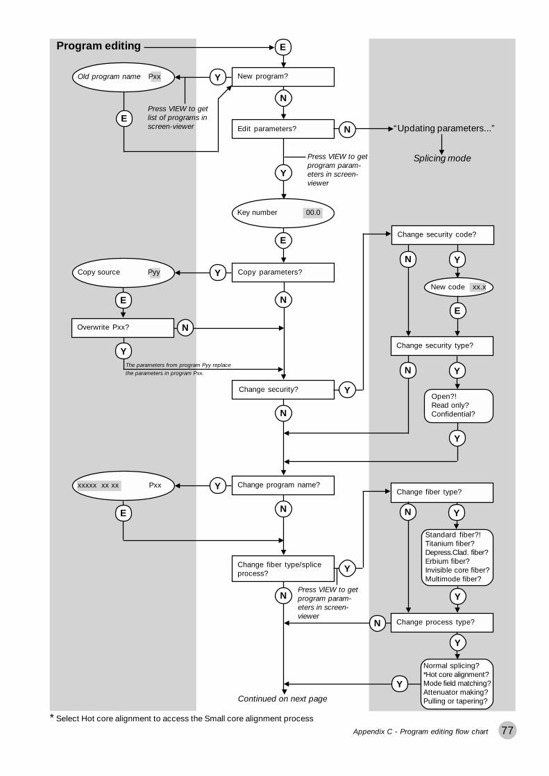
77
Program editing E
New program?Old program name Pxx Y
EPress VIEW to getlist of programs inscreen-viewer Edit parameters?
N
Y
Press VIEW to getprogram param-eters in screen-viewer
N “Updating parameters...”
Splicing mode
Key number 00.0
E
Copy source Pyy Y
E
Overwrite Pxx?
Y
N
N
The parameters from program Pyy replace
the parameters in program Pxx.
Copy parameters?
Change security code?
New code xx.x
Y
Y
Change security type?
E
N
YN
Open?!Read only?Confidential?
Y
N
Change program name?xxxxx xx xx Pxx Y
E
Change fiber type?
Y
Change process type?
N
Y
Normal splicing?*Hot core alignment?Mode field matching?Attenuator making?Pulling or tapering?
Change fiber type/spliceprocess?
N
Standard fiber?!Titanium fiber?Depress.Clad. fiber?Erbium fiber?Invisible core fiber?Multimode fiber?
YN
N
Y
Y
Continued on next page
Press VIEW to getprogram param-eters in screen-viewer
Change security?
Appendix C - Program editing flow chart
* Select Hot core alignment to access the Small core alignment process

78
Continued from previous page
Edit control parameters?Control parameter 1 Y
E Press VIEW to getprogram parametersin screen-viewer
This question doesnot appear if you areusing the normalsplicing process
Depending on the process“Control parameter 1” is:Max eccentricity,Index limit,Desired attenuation, orPull 1
Control parameter 2
E
Depending on the process“Control parameter 2” is:RTC current,Threshold type,Offset adjustment, orPull 2
Control parameter 3
E
Depending on the process“Control parameter 3” is:Acceptable offset,Loss factor,ECF factor, orPull 3
Edit splicing parameters?
N
Y
Press VIEW to getprogram param-eters in screen-viewer
Prefuse time 0.2 s
N
Re-edit program?
Change security?
Y
Press VIEW to getprogram parametersin screen-viewer
Follow from same question inthe middle of the previous page
N
“Updating parameters...”
Splicing mode
Appendix C - Program editing flow chart
E
E
Prefuse current 10.0 mA
Gap 50.0 �m
Overlap 10.0 �m
Fusion time 1 0.3 s
Fusion current 1 10.5 mA
Fusion time 2 2.0 s
Fusion current 2 16.3 mA
Fusion time 3 2.0 s
Fusion current 3 12.5 mA
Left MFD 9.8 �m
Right MFD 9.8 �m
Set center position 255
AOA current 0.0 mA
Early prefusion No
Align accuracy 0.15 �m
Loss shift 0 db
Auto Arc Center No
E
E
E
E
E
E
E
E
E
E
E
E
E
E
E
E

79Appendix C - Service functions flow chart
Service functions
Current test?
N
The current test isavailable only if youare using hot corealignment process.Other wise thequestion does notappear.
Clean electrodes?
Y
The current test willnot run until after
you have gonethrough the otherservice functions.
Y Electrodes cleaning program runs
Splicing mode
N
Splicelist handling? Y Splice list OnChange splice list on/off? Y
N
Operator Number 00Change list codes? Y
E
List code 1 00
List code 2 00
E
E
N
E
Enter service mode?
N
N
Splicing mode
FuseIf you chose the current test, youstart it at this point by pressing FUSE.
Current test runs
#
If you have sufficient splice-listdata, you can print. Print splicelist?
YN
Clear splicelist?
Y Nor
Skip last splice?
Y Nor

80 Index
A
Acceptable offset 29, 37, 38Align accuracy 40, 56Alignment
fine 17, 19rough 18
Altitude, compensation for 61, 64AOA current 40, 56Arrow buttons 7, 18, 47Attenuator making. See Splicing
processes: attenuator makingAutomatic arc re-centering 40, 56Automode 12, 14Autoxct offset 55, 56, 62AUX-connector 74
B
Base line tilting 60Battery 8
charging 66checking voltage 66low level warning 66
Binary parameter values 54Buttons (overview) 7
C
Carrying case 5, 6Character selection 47. See also
Quick character selectionCleaning
electrodes 68fiber clamps 67fiber during preparation 10V-grooves 10, 67
Cleave angle. See Gap angleCleaving 11
cleaving lengths 11Cold image 21Control parameters 37, 49Core 22
eccentricity 22, 28, 29, 37, 38CPU settings 62Current test 57
D
Date/time 62Desired attentuation 34, 38Display gap angle 61, 63
E
Early prefusion 40, 56ECF factor 30, 34, 38Electrode brush 6Electrode warning 62Electrodes 6
changing 69cleaning program 5, 58, 68maintenance 5, 68safety 5
Enter button 53Erbium splicing. See Splicing
processes: erbium splicingEscape button 7External monitor 74
F
Fault messages 17, 71Faults, observable 73Fiber clamps 6, 12, 23
maintenance 67Fiber fixtures 6, 23Fiber insertion 12Fiber preparation 10
defects 13Fiber types 26, 36, 48
depressed cladding 27dispersion shifted 27erbium 26invisible core 27multimode 26silica core 27
Focusing monitor 7Fuse button 7, 17, 20Fuses 7
replacing 66Fusion current parameters 39Fusion time parameters 39
G
Gap 39Gap angle 63Gap button 7, 19Gap close intensity 30, 38Global parameters 61Global xct 55, 62
H
Heat oven 6, 23Heat-shrinkable sleeve 10, 23Hot core alignment. See Splicing
processes: hot core alignmentHot fiber index profile 31Hot images 4, 21, 22, 60
button 7Humidity 5
I
Index limit 31, 33, 37Using the ... 33
Index profile. See Hot fiber indexprofile
K
Key number. See Security
L
Language, changing 61Left MFD 34, 40, 55Light intensity curves 60Loss estimation level 62Loss factor 31, 37Loss shift 40, 56
M
Macrobending 62Maintenance 5, 66
battery 66electrodes 68fiber clamps 67fuses 66mirror one 70time table 70V-grooves 67
Manual mode 14Matchsticking 27. See also Splic-
ing defectsMax eccentricity 29, 37, 38Max gap angle 61Max view angle 61Message field 7, 43
Index

81
MFD matching point 33Mirror one 70Mode button 7, 14Mode coupling theory 4Mode field 7, 43Mode field diameters 31, 34, 55Monitor
controls 7description 7
Multiple value parameters 54
N
Navigation 53No button 53Number buttons 53
O
Offset adjustment 34, 38On/Off button 7Overlap 39
P
Parameter editing review 53Power
connecting 8input 7, 8supply 8
Pre-defined programs. See Splicingprograms: Programs 01-10
Prefuse current 39Prefuse time 39Prefusion 17, 19Printer connection 74Printing splice-lists 59Program editing mode 44Program parameters 36
general 36control. See Control parameterssplicing. See Splicing parameters
Programming buttons 7Programs 01-10. See Splicing
programs: Programs 01-10Programs 11-50. See Splicing
programs: editablePull parameters 35, 38Pulling distance 30, 38
Q
Quantitative parameter values 54Quick character selection 61
R
Real time control (RTC) 29Rear panel 7Right MFD 34, 40, 55Rough alignment 18RSR 232 7, 74RTC 28RTC current 29, 37, 38, 57
RTC current high 62RTC current low 62
RTC cycle 28
S
Safety 5Safety shield 5, 6, 12, 13Screen viewer 15, 16Security 44, 46
code 36, 46type 36, 46
Service functions 57Service mode 59Set center position 40, 55Set-up checklist 8Show loss to 62Small core alignment. See Splicing
processes: small core alignmentSource program 45Splice counter 62, 68Splice evaluation 21Splice loss 4, 21
estimation 21Splice loss estimation 4
parameters 62Splice protection 23Splice-list handling 58
list codes 58operator number 58printing out 59
Splicing mode (definition) 16Splicing mode selection 14Splicing parameters 39, 51splicing position 55Splicing processes 4, 28, 36, 49
attenuator making 4, 16, 34, 38erbium splicing 4, 26, 31hot core alignment 16, 29, 37
Index
mode field matching 16, 31, 37normal 16, 28pulling or tapering 4, 16, 35, 38small core alignment 30, 38
Splicing programseditable 4, 43naming 26, 36, 47Programs 01-10 4, 16, 26, 41selection 14
Splicing quick guide 9Stop at fusion 61Stripping 10Surface tension 29, 34, 38
T
Tapering. See Splicing processes:pulling or tapering
Target offset 34, 38Threshold type 31, 37
difference 32higher index 32higher start 32left index 32right index 32
Threshold type test 31, 32Tool set 6Turn off 9, 62
U
Upload / download software 65
V
V-grooves 6, 8, 12black 6, 8, 11blue 6, 8, 11changing 67maintenance 5, 67numbers 67
Video output 7View angle 63View button 53Viewing fibers 7
W
Wait time 62Weight factor 62
Y
Yes button 53

82 Ericsson representatives
Ericsson representatives
ArgentinaReycom electrónica S.A.Bernardo de Irigoyen 972 Piso 6°1304 Buenos Airestel: (54-1) 307-2185
BelgiumPhase-Optic S.A.Z. A. de Vaubesnard7 chemin de VaubesnardF-91410 Dourdan Francetel: +33 1 645512 00
BrazilASGA Microelectrónica S.A.Rodovia Dr. Roberto MoreiraKm 4-CP 13213140-000 Paulínia, SPtel: 55 19 8442020
CanadaAmherst Fiber OpticsBrentwood Commons Two,Suite 205750 Old Hickory Blvd.Brentwood, TN 37027 USAtel: +1 (615) 376-4396
ChinaWall International GroupVantone Plaza, Room B1606No. 2 Fu Cheng Men WaiStreetBeijing 100037tel: 86 10 68579091
Czech RepublicHKE, spol. s.r.o.Na Cikorce 3CZ-143 00 Prague 4tel: 420 2 402 6889
DenmarkEricsson Components Dist.Sluseholmen 8DK-1790 Copenhagen Vtel: +45 33883101
FinlandViikinkikaapeli OySierakiventie 8SF-02780 Espootel: +358 9 299 65 00
FrancePhase-Optic S.A.Z. A. de Vaubesnard7 chemin de VaubesnardF-91410 Dourdantel: +33 1 64551200
GermanyMacrotron SystemsAmmerthalstrasse 7D-85551 Kirchheimtel: +49 8 945 111 283
Hong KongComtecFar East Reg OfficeRm. 607, Austin Tower, 22-26AAustin Ave.Tsim shatsui, Kowloontel: +852 23 112 263
IndiaSubex Systems Ltd.721, 7th MainMahalaxmi LayoutBangalore – 560 086tel: +91 80 3327581
Ericsson Comm. Pvt. Ltd.The Great Eastern Plaza2-A Bhikaji Cama PlaceNew Dehli 110 066tel: +91 11 6180808
IndonesiaEricsson Indonesia P.T.Wasma Pondok Indah, 10th Fl.JL Sultan IskandarMuda V. TAJakarta 12310tel: 62 21 7693555
ItalyAdvance Italia SrlVia F. lli Cernuschi 22I-22055 Merate (LC)tel: +39 039 990 7612
JapanSeiko Instruments Inc.8, Nakase 1-chomeMihama-kuChiba-shiChiba 261-8507tel: +81 043-211-1337
MalaysiaCommunication Techn. SdnBhdNo 6, Lot 291, Jalan TP5Taman Perindustrian UEP47600 Petaling JayaSelangor Darul Ehsantel: 6 037 047 888
MexicoAmherst Fiber OpticsBrentwood Commons Two,Suite 205750 Old Hickory Blvd.Brentwood, TN 37027 USAtel: +1 (615) 376-4396
The NetherlandsRexcom Holland B.V.Patroonstraat 11NL-3860 BC Nijerktel: +31 33 246 12 44
NorwayFOSS ASKobbervikdalen 93BPostboks 3614N-3007 Drammentel: +47 32 21 08 15
PhilippinesEricsson Telecomm. Inc.7th Floor Octagon Bldg.San Miguel AvenueOrtigas CenterPO Box 136 43Pasig City 1600tel: 63 2 6371600
PolandP.U.H. Interlab s.c.ul. Potocka 14Pawilon 3PL-01-641 Warsawtel: +48 22 8333956
SingaporeTele Dynamics Pte LtdBLK 9010, Tampines St 93#03 - 107Singapore 52 884tel: 6 578 628 888
South AfricaLambda Test Equipment c.c.PO Box 113Pespsequor TechnoparkPretoria 0020tel: +27 12 3491341
South KoreaATC Electronics99-1 Nackwon-DongChongro-GuSeoultel: +82 27651177
SwedenInterscandinavia Telecom ABJakobs Westins gatan 1BS-104 22 Stockholmtel: +46 8 441 1995
SwitzerlandEricsson AGStationstrasse 5CH-8306 Bruttisellentel: +41 1 8053314
TaiwanRock & Brothers Ent. Ltd.No19-1, Lane 1Alley 176Fu Ten One (1) RoadHsichin ChewTaipei Hsiewtel: 866226931888
ThailandEricsson Thailand Ltd21st floor, The Suntowers Bldg B123 Vibhavadee Rangsit Rd.Chatuchak 109 00Bangkoktel: +66 2 2997000
TurkeyEricsson Telekommunikasjon ASBranch OfficeCinnah CaddesiNo. 41/10-1306680 CankayaAnkaratel: +90 3126151500
Tele SiteTelekommunikasjon Ltd.Nenehatun Caddesi 28/2Gaziosmanpasa067 00 Ankaratel: +90 3124472500
United KingdomComtec Cable Accessories LtdNorman Way Ind. EstateOver, Cambridge CB4 5QEtel: +44 1 954 232 056
United StatesAmherst Fiber OpticsBrentwood Commons Two,Suite 205750 Old Hickory Blvd.Brentwood, TN 37027tel: +1 (615) 376-4396
UruguayReycom electrónica S.A.Bernardo de Irigoyen 972 Piso 6°1304 Buenos AiresArgentinatel: (54-1) 307-2185

83

84
Ericsson Cables ABNetwork ProductsLandsvägen 66S-172 87 Sundbyberg, SWEDENTel:+46 8 764 0900Telex: 14723 ERINET STelefax:+46 8 98 5503
133ST010133TB001R1
Ericsson Cables ABc