SF-CHAMP 5 - FROGGER - San Francisco's Newly-updated Travel Model

EE307
Frogger Project #2
Zach Miller & John Tooker
Lab Work: 11/11/2008 - 11/23/2008
Report: 11/25/2008
This document details the work completed on the Frogger project from its conception and design, through its implementation and societal impact. The Frogger project is a recreation of the Frogger arcade game, implemented in hardware on an FPGA. The user interacts with the system via a keyboard; the game is displayed on a VGA monitor.

Page ii
Table of Contents Abstract ......................................................................................................................................................... 1
Introduction .................................................................................................................................................. 1
Terms and Acronyms ................................................................................................................................ 2
Background and Theory ................................................................................................................................ 3
Frogger Game Mechanics ......................................................................................................................... 3
Standard Game Mechanics ................................................................................................................... 3
FPGA Implementation ............................................................................................................................... 4
Design ............................................................................................................................................................ 4
Requirements ............................................................................................................................................ 4
Interfaces .................................................................................................................................................. 5
Keyboard Input...................................................................................................................................... 6
VGA Video ............................................................................................................................................. 6
Components .............................................................................................................................................. 9
Controller ............................................................................................................................................ 11
Procedure and Implementation .................................................................................................................. 12
Results and Discussion ................................................................................................................................ 15
Had We More Time ................................................................................................................................. 15
Standards and Society Impact ..................................................................................................................... 15
Conclusions ................................................................................................................................................. 16
References .................................................................................................................................................. 17

Page 1
Abstract
This document details the work completed on the Frogger project from its conception and design,
through its implementation and societal impact. The Frogger project is a recreation of the Frogger
arcade game, implemented in hardware on an FPGA. The user interacts with the system via a keyboard;
the game is displayed on a VGA monitor.
Introduction
The purpose of the Frogger project was to recreate an old game in a recognizable form. The project
offers intrigue due to the nature of the game as well as the challenge of working at the hardware level
with not only the FPGA itself but also a VGA monitor and keyboard. The project was successfully
completed and the team was able to capture the feel of the Frogger game.
The project offered several challenges that the team felt gave this project extra merit, besides the
obvious difficulty of interfacing with the VGA output and keyboard input. One such challenge was
moving the frog left and right based both on the keyboard (sampled at one rate) as well as based on
which log the frog was on (each row generating a different clock rate). Reconstructing the drivers for
the VGA output also gave the team many challenges. By rewriting the VGA output drivers, the team was
able to tightly couple the logic for the Frogger game with the display logic. While traditionally tight
coupling should be avoided, in this case it allowed the project to use a smaller percentage of the FGPA’s
logic elements as well as increases the efficiency of the project and remove screen ‘blips’. Due to the
tight coupling of the VGA output and the forced refresh rate of 60 Hz, the team was forced to optimize
various circuit components using redundancy techniques learned in ELEC 370. The details of this as well
as other challenges will be discussed later in the design section.

Page 2
Terms and Acronyms
Please see Table 1 on the next page for terms and acronyms used throughout this report.
Table 1: Terms and Acronyms
Term Definition
FPGA (Field Programmable Gate Array) A generic hardware
device capable of implementing a wide array of logical
functions.
LFSR (Wikipedia, 2008) (Linear Feedback Shift Register) A common hardware
implementation for a pseudo-random number
generator.
Quartus II A software package that, among other things, can
compile VHDL and program the resulting logic to an
FPGA.
RAM (Random Access Memory) A common volatile storage
device that allows access to write or read from different
addresses in any order.
ROM (Read Only Memory) like RAM, but read only.
VGA Video Graphics Array: “standard” screen size of 640 by
480 pixels.
VHDL (VHSIC Hardware Description Language) A language
used to concisely express logical functions that can be
compiled and programmed on an FPGA.
VHSIC (Very High Speed Integrated Circuit) For example, an
FPGA.

Page 3
Background and Theory
This section presents any prior knowledge necessary for the reader to understand the implementation
of the project.
Frogger Game Mechanics
The typical Frogger game consists of a fixed overhead view of a street and a river. A typical game can be
seen in Figure 1 below.
Figure 1: Frogger Game
Standard Game Mechanics
The game begins at level zero; this level is easiest due to the relatively slow speed of traffic and the
river. The user attempts to “jump” the frog to the other end of the screen while navigating multiple
obstacles. If the frog touches a car or falls into the water (i.e. missed a jump to the next log) the level is

Page 4
restart and a life is subtracted. If the user is able to successfully reach the other side, the game
progresses to the next level, which means faster traffic and water.
The game progresses through a set number of levels, when the user completes the last level, they win
the game. On the other hand, if the user depletes their store of extra lives, the game will be lost. Other
basic game information is a life counter, current level display, and the user’s score.
FPGA Implementation
The team decided to implement Frogger on an Altera Flex 10k (EPF10k70) FPGA. This FPGA was selected
due to the fact that John Tooker already owned the FPGA which contained a keyboard connection and
VGA output.
Design
This section discusses the design of the Frogger project, starting with high level descriptions and working
down to the lower level implementation details.
Requirements
The primary requirements for the project are listed below. Most of these requirements are implicit in
the implementation of a game mimicking the traditional Frogger game.
1. Game contains a start lane, middle safe lane, and finish lane.
2. Four lanes of traffic
3. Four lanes of logs (in water)
4. As each level is passed, the speed of the traffic and logs are increased
5. If the user’s frog comes into direct contact with water or a vehicle a life is lost (start with more
than one live)

Page 5
6. Cars and logs appear randomly and with random length (additionally, minimum and maximum
lengths are enforced both for empty spaces as well as lengths of logs and cars)
7. If the user is able to successfully complete the 7th level the game is won.
8. The user receives a score for each level based on the length of time spent to complete it
9. Special display for frogs no longer living (smashed on the road or drowned in the water)
10. Indication of either victory or defeat.
11. Logic should not interfere with the 60 Hz frame rate display.
Interfaces
Frogger requires a responsive interface between the user and the game logic. A standard keyboard and
VGA enabled monitor satisfy these conditions because of the speed of the programmable hardware (the
FPGA).
Figure 2: Altera FPGA
The keyboard and VGA hardware was provided, but needed alteration.

Page 6
Keyboard Input
The keyboard ‘drivers’ that were provided gave a registered (clocked) keyboard code, a pulse when a
new key is pressed and another signal that tells when the keyboard logic is ready for another key to be
pressed. This registered code remains unchanged until another key is pressed. This is not sufficient for
this project’s purposes because the user may need to press the same key down multiple times in a row.
So, as shown in Figure 3, the character code is reregistered again on consecutive inputs and cleared
after each key code is ‘read’.
Figure 3: Keyboard Logic
VGA Video
The VGA drivers required some additional changes in logic. The model displays a character array on the
screen, each character is 8 pixels wide by 8 pixels high, and the given resolution is 20 characters across
the screen by 15 characters down. This given model takes ASCII values from a RAM block, whose
address is fed by the character address that is currently being displayed. To change what is being
displayed, you need to either over write the current address (which makes ‘random’ pixels on the screen
flash) or only write to a certain address when the VGA adapter logic is reading from that address.
The team threw out the RAM memory, and fed the display adapter ASCII codes depending directly on
the hardware. This can be roughly seen in Figure 4 where the rightmost MUX selects a different ASCII
value (which also depends on other logic) to display on the screen.

Page 7
Figure 4: Display Logic

Page 8
The project does use a ROM memory for the static display elements (i.e. the menu boarder), and
this blinks when the game ends. The score, lives, and level are translated from binary arrays to
ASCII values (4 bits for every ASCII character).
The river and the road areas use a MUX to select whether this particular character should be a
log or river (road or bus) which is driven by other logic not shown in Figure 4, but consists of
choosing which shift register corresponds to the row that is displayed and then applying the
current address modulo 20 (the number of columns in each row) as the select line to the MUX
that chooses whether or not a log or river character is displayed. This worked up until address
256 (there are 300 addresses on a 20x15 display). After this address, the display logic became
too slow to refresh the screen accurately, so the team added other simpler logic (but more of it)
in place of the modulo 20 logic. And if it is at an address over 256, a shorter, though more
verbose, logic is selected.
The frog position takes precedence on the display and uses similar logic to determine whether
the frog is alive or not, as well as how it should look when it is alive and dead (depending if it is
on a log or ground, or gets squished by a bus or drowned in the river).

Page 9
Components
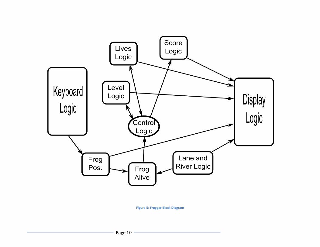
The implementation of the Frogger project is split into the following basic components. Refer to Figure
5: Frogger Block Diagram, next page, for a block diagram showing how the modules are connected
together.
1. Control Logic – dictates when to reset, start new levels, subtract lives, add score, etc.
2. Score Logic – keeps track of score for each level (decrements ever microsecond) and adds this to
the total score when told to.
3. Lives and Level Logic – These are very similar, one decreases and one increases. The lives logic
dictates when the end of the game is reached due to deaths and the level logic determines the
difficulty of the game as well when the game is won.
4. Input and Display – see Interfaces section above.
5. Frog Position – works with the keyboard logic to move the frog left or right (by shifting a
register) or moving it up or down while keeping the frog on the screen.
6. Log and Car positions – LFSR random logic produces pseudo-random numbers independently
into multiple shift registers which correspond to where the logs/cars are on the screen. This
logic is hooked up to the display as well as additional circuitry to determine if the frog has been
killed or not.
7. Frog livelihood – logic that compares frog position to that of the busses and river to determine
when the frog has been killed or not.
8. Clock – The hardware uses multiple clocks, all derived from the 25.175MHz clock included on
the board. This clock is slowed down to various frequencies to control the score, lane speed,
etc.
Page 10
Figure 5: Frogger Block Diagram

Page 11
Controller
Figure 6: Controller State Diagram, below, shows the high-level state transition diagram for the
Controller component. The state transitions match the basic game flow as described in the Introduction.
Figure 6: Controller State Diagram
Page 12
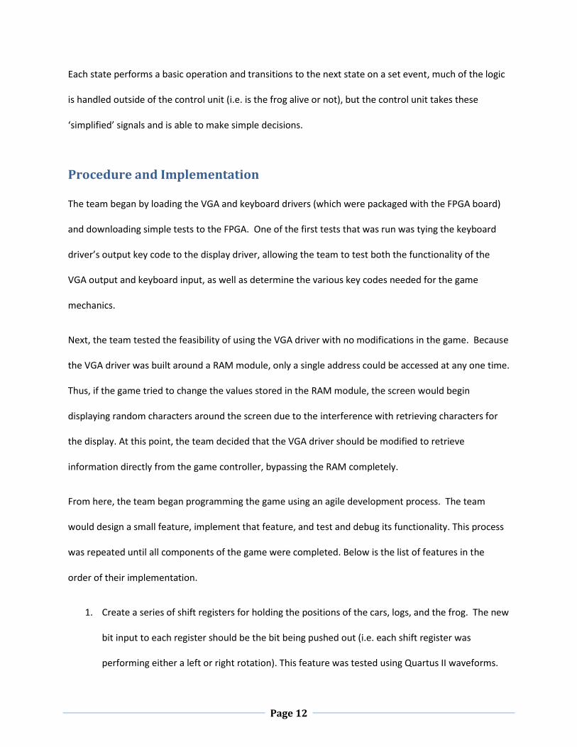
Each state performs a basic operation and transitions to the next state on a set event, much of the logic
is handled outside of the control unit (i.e. is the frog alive or not), but the control unit takes these
‘simplified’ signals and is able to make simple decisions.
Procedure and Implementation
The team began by loading the VGA and keyboard drivers (which were packaged with the FPGA board)
and downloading simple tests to the FPGA. One of the first tests that was run was tying the keyboard
driver’s output key code to the display driver, allowing the team to test both the functionality of the
VGA output and keyboard input, as well as determine the various key codes needed for the game
mechanics.
Next, the team tested the feasibility of using the VGA driver with no modifications in the game. Because
the VGA driver was built around a RAM module, only a single address could be accessed at any one time.
Thus, if the game tried to change the values stored in the RAM module, the screen would begin
displaying random characters around the screen due to the interference with retrieving characters for
the display. At this point, the team decided that the VGA driver should be modified to retrieve
information directly from the game controller, bypassing the RAM completely.
From here, the team began programming the game using an agile development process. The team
would design a small feature, implement that feature, and test and debug its functionality. This process
was repeated until all components of the game were completed. Below is the list of features in the
order of their implementation.
1. Create a series of shift registers for holding the positions of the cars, logs, and the frog. The new
bit input to each register should be the bit being pushed out (i.e. each shift register was
performing either a left or right rotation). This feature was tested using Quartus II waveforms.
Page 13
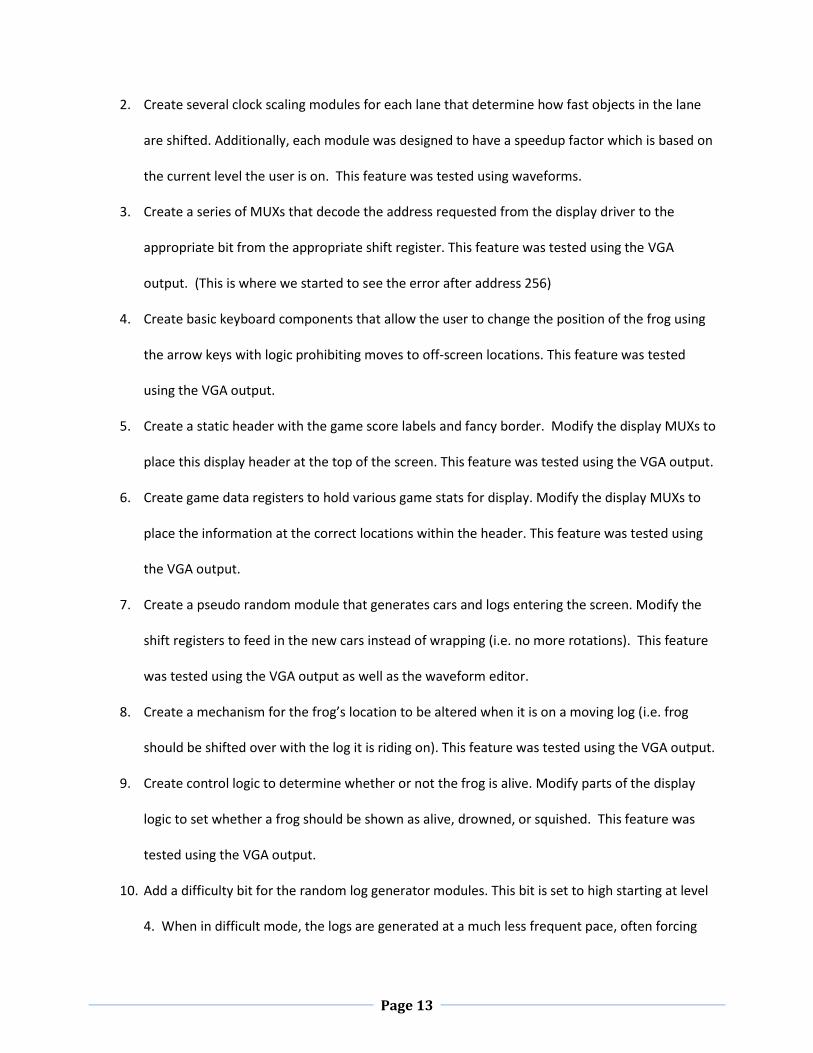
2. Create several clock scaling modules for each lane that determine how fast objects in the lane
are shifted. Additionally, each module was designed to have a speedup factor which is based on
the current level the user is on. This feature was tested using waveforms.
3. Create a series of MUXs that decode the address requested from the display driver to the
appropriate bit from the appropriate shift register. This feature was tested using the VGA
output. (This is where we started to see the error after address 256)
4. Create basic keyboard components that allow the user to change the position of the frog using
the arrow keys with logic prohibiting moves to off-screen locations. This feature was tested
using the VGA output.
5. Create a static header with the game score labels and fancy border. Modify the display MUXs to
place this display header at the top of the screen. This feature was tested using the VGA output.
6. Create game data registers to hold various game stats for display. Modify the display MUXs to
place the information at the correct locations within the header. This feature was tested using
the VGA output.
7. Create a pseudo random module that generates cars and logs entering the screen. Modify the
shift registers to feed in the new cars instead of wrapping (i.e. no more rotations). This feature
was tested using the VGA output as well as the waveform editor.
8. Create a mechanism for the frog’s location to be altered when it is on a moving log (i.e. frog
should be shifted over with the log it is riding on). This feature was tested using the VGA output.
9. Create control logic to determine whether or not the frog is alive. Modify parts of the display
logic to set whether a frog should be shown as alive, drowned, or squished. This feature was
tested using the VGA output.
10. Add a difficulty bit for the random log generator modules. This bit is set to high starting at level
4. When in difficult mode, the logs are generated at a much less frequent pace, often forcing

Page 14
the user to jump backwards to avoid being pushed off the end of the screen when no logs are
available in the next water lane. This feature was tested using the VGA output.
11. Implement actual logic for lives counter, score, and current level (instead of just displaying the
default register values). This feature was tested using the VGA output.
12. Implement end of game logic for either running out of lives or completing the last level. This
feature was tested using the VGA output.
13. Create an end of game notification. Notification is based on flashing the static header content
at a rate based on the highest level reached. This feature was tested using the VGA output.
14. Link the Esc key to reset (as so the user does not have to hit the reset button on the actual
FPGA). This feature was tested using the VGA output.
Finally, two major bugs were resolved near the end of the development.
15. Frog would die when riding at the very end of a log. This was due to the fact that propagation
delays for the frog’s movement with the log were delayed long enough for the game controller
to see the frog as being off of the log. To avoid this, the team implemented a “de-bouncer” for
the frog dead wire. The frog would only be shown as dead if the wire was high two clock cycles
in a row. This modification was tested using the VGA output.
16. Display squares near the bottom of the screen appeared to be completely wrong. After some
testing, it was determined that each square was showing up as being shifted over by six
positions (give or take). The team determined that this error occurred when the display address
was at values over 255. To avoid this, the team implemented two separate display logic
sections, one for values including and below 255 and one for values above 255. Which value
shown was then selected by the most significant bit of the address line (bit ). This
modification was tested using the VGA output.
Page 15
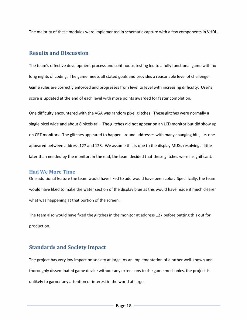
The majority of these modules were implemented in schematic capture with a few components in VHDL.
Results and Discussion
The team’s effective development process and continuous testing led to a fully functional game with no
long nights of coding. The game meets all stated goals and provides a reasonable level of challenge.
Game rules are correctly enforced and progresses from level to level with increasing difficulty. User’s
score is updated at the end of each level with more points awarded for faster completion.
One difficulty encountered with the VGA was random pixel glitches. These glitches were normally a
single pixel wide and about 8 pixels tall. The glitches did not appear on an LCD monitor but did show up
on CRT monitors. The glitches appeared to happen around addresses with many changing bits, i.e. one
appeared between address 127 and 128. We assume this is due to the display MUXs resolving a little
later than needed by the monitor. In the end, the team decided that these glitches were insignificant.
Had We More Time One additional feature the team would have liked to add would have been color. Specifically, the team
would have liked to make the water section of the display blue as this would have made it much clearer
what was happening at that portion of the screen.
The team also would have fixed the glitches in the monitor at address 127 before putting this out for
production.
Standards and Society Impact
The project has very low impact on society at large. As an implementation of a rather well-known and
thoroughly disseminated game device without any extensions to the game mechanics, the project is
unlikely to garner any attention or interest in the world at large.

Page 16
The team kept the standards of the arcade Frogger game. The keyboard hardware is PS\2 compliant and
the display logic is VGA compatible.
Conclusions
The team was able to successfully recreate the Frogger game which is playable and challenging. Through
the implementation of the various components in schematic capture, the team was able to strengthen
their skills as various challenges were solved. Finally, the team was very pleased with the final results of
the project and felt that the simple agile development process used was a great help in the success of
the project.
Figure 7: Screenshot of Final Project

Page 17
References
Wikipedia. (2008, November 3). Linear Feedback Shift Register. Retrieved November 3, 2008, from
Wikipedia: http://en.wikipedia.org/wiki/LFSR