Friction Experiment of Linear Motion Roller Guide...
7
INTERNATIONAL JOURNAL OF PRECISION ENGINEERING AND MANUFACTURING Vol. 15, No. 3, pp. 545-551 MARCH 2014 / 545 © KSPE and Springer 2014 Friction Experiment of Linear Motion Roller Guide THK SRG25 De-Jun Cheng 1 , Wan-Suk Yang 1 , Je-Hong Park 1 , Tae-Jo Park 1 , Su-Jin Kim 1,# , Gyung-Ho Kim 2 , and Chun-Hong Park 2 1 Department of Mechanical Engineering, Gyeongsang National University, Jinju, Korea 2 Korea Institute of Machinery & Materials, Daejeon, Korea # Corresponding Author / E-mail: [email protected], TEL: +825-5772-1636, FAX: +825-5772-1577 KEYWORDS: LM roller guide, External load, Dynamic friction, Stribeck effect, Coulomb friction, Viscous friction Friction is a characteristic that can be found in machine elements in common engineering use, and it has great effect on the machining performance of a machine tool. Linear motion (LM) guides supported by rolling elements are used for accurate positioning of precision machine. For accurate positioning, the frictional behavior of the LM guide must be understood. In this investigation, a new experiment is conducted to measure friction, and the behavior of LM roller guide friction is measured under various external loads, preloads, velocities, and lubricants. The results obtained from experiment are compared with reference data, and the experimental friction equation of LM roller guide THK SRG25 is achieved from experiment, which can be used to calculate LM roller guide friction and control positioning accuracy. Manuscript received: September 6, 2013 / Revised: December 10, 2013 / Accepted: January 12, 2014 1. Introduction Linear motion (LM) guides have been widely used for precise positioning devices to transport machine parts through a linear path in machining centers and X-Y tables etc. As machine parts becoming smaller and finer, the required order of precision has been increased. 1 LM guides using roller bearing have many advantages such as high stiffness, smooth motion. Linear motion guides also have a low friction coefficient compared with sliding contact bearings. Usually, the static friction is small and almost the same as dynamic friction. However, high static friction with lower kinematic viscosity results in stick slip, wherein the coefficient is separated and the difference between them increases with increasing preload. 2 Therefore, the study of LM guide friction plays a crucial role in the machining center. Andersson et al. 3 deals with different friction models for sliding contacts running under different conditions, friction models which have been studied are: Coulomb friction model, Viscous friction model, Stribeck effect model, Combined Coulomb and Viscous friction model. The friction was observed by several authors 4-9 that the variation of friction depends on interfacial conditions such as sliding speed, the normal load, temperature, stick slip and vibration. When using an LM system, it is necessary to provide effective lubrication, where the main function of lubricant is the reduction of both friction and wear of the rolling elements. There has been a great deal of research conducted in relation to the influence of lubrication on journal bearing friction. However, only few studies have been proposed to learn the influence of lubrication on the LM guide friction. NOMENCLATURE F = Friction force (N) f 0 = Base friction force (N) k 1 = Factor dependent on the type of bearing k 2 = Factor dependent on the type of bearing (1/µm) P = External load (N) 1.5 for Normal p c = Preload class (µm) 2.5 for C 1 preload 3.5 for C 0 preload V St = Sliding speed coefficient in the Stribeck force (m/s) V = Sliding speed (m/s) ν = Kinematic viscosity (mm 2 /s) µ St = Stribeck effect force coefficient (kNmm/s) µ v = Viscous friction coefficient (Ns 2 /mm 4 ) DOI: 10.1007/s12541-014-0369-y
-
Upload
vuongtuong -
Category
Documents
-
view
226 -
download
1
Transcript of Friction Experiment of Linear Motion Roller Guide...

INTERNATIONAL JOURNAL OF PRECISION ENGINEERING AND MANUFACTURING Vol. 15, No. 3, pp. 545-551 MARCH 2014 / 545
© KSPE and Springer 2014
Friction Experiment of Linear Motion Roller Guide THK
SRG25
De-Jun Cheng1, Wan-Suk Yang1, Je-Hong Park1, Tae-Jo Park1, Su-Jin Kim1,#, Gyung-Ho Kim2, and Chun-Hong Park2
1 Department of Mechanical Engineering, Gyeongsang National University, Jinju, Korea2 Korea Institute of Machinery & Materials, Daejeon, Korea
# Corresponding Author / E-mail: [email protected], TEL: +825-5772-1636, FAX: +825-5772-1577
KEYWORDS: LM roller guide, External load, Dynamic friction, Stribeck effect, Coulomb friction, Viscous friction
Friction is a characteristic that can be found in machine elements in common engineering use, and it has great effect on the machining
performance of a machine tool. Linear motion (LM) guides supported by rolling elements are used for accurate positioning of
precision machine. For accurate positioning, the frictional behavior of the LM guide must be understood. In this investigation, a new
experiment is conducted to measure friction, and the behavior of LM roller guide friction is measured under various external loads,
preloads, velocities, and lubricants. The results obtained from experiment are compared with reference data, and the experimental
friction equation of LM roller guide THK SRG25 is achieved from experiment, which can be used to calculate LM roller guide friction
and control positioning accuracy.
Manuscript received: September 6, 2013 / Revised: December 10, 2013 / Accepted: January 12, 2014
1. Introduction
Linear motion (LM) guides have been widely used for precise
positioning devices to transport machine parts through a linear path in
machining centers and X-Y tables etc. As machine parts becoming
smaller and finer, the required order of precision has been increased.1
LM guides using roller bearing have many advantages such as high
stiffness, smooth motion. Linear motion guides also have a low friction
coefficient compared with sliding contact bearings. Usually, the static
friction is small and almost the same as dynamic friction. However,
high static friction with lower kinematic viscosity results in stick slip,
wherein the coefficient is separated and the difference between them
increases with increasing preload.2 Therefore, the study of LM guide
friction plays a crucial role in the machining center.
Andersson et al.3 deals with different friction models for sliding
contacts running under different conditions, friction models which have
been studied are: Coulomb friction model, Viscous friction model,
Stribeck effect model, Combined Coulomb and Viscous friction model.
The friction was observed by several authors4-9 that the variation of
friction depends on interfacial conditions such as sliding speed, the
normal load, temperature, stick slip and vibration.
When using an LM system, it is necessary to provide effective
lubrication, where the main function of lubricant is the reduction of
both friction and wear of the rolling elements. There has been a great
deal of research conducted in relation to the influence of lubrication on
journal bearing friction. However, only few studies have been proposed
to learn the influence of lubrication on the LM guide friction.
NOMENCLATURE
F = Friction force (N)
f0 = Base friction force (N)
k1 = Factor dependent on the type of bearing
k2 = Factor dependent on the type of bearing (1/µm)
P = External load (N)
1.5 for Normal
pc = Preload class (µm) 2.5 for C1 preload
3.5 for C0 preload
VSt = Sliding speed coefficient in the Stribeck force (m/s)
V = Sliding speed (m/s)
ν = Kinematic viscosity (mm2/s)
µSt = Stribeck effect force coefficient (kNmm/s)
µv = Viscous friction coefficient (Ns2/mm4)
DOI: 10.1007/s12541-014-0369-y
546 / MARCH 2014 INTERNATIONAL JOURNAL OF PRECISION ENGINEERING AND MANUFACTURING Vol. 15, No. 3
The purpose of this research is to characterize the friction force of
LM Roller guide. A series of experiments are carried out to measure
friction, which consider the effects of external load, preload, velocity
and lubricant on LM roller guide friction. To characterize these
components, a new experimental method in which external load can be
applied easier is suggested to measure friction. Finally the experimental
equation achieved from experimental results can be used to calculate
LM Roller guide (THK SRG25) friction and the relationship among
friction characteristic, external load, preload, velocity and lubrication
can be analyzed using this empirical equation.
2. Experiment Method and Equipment
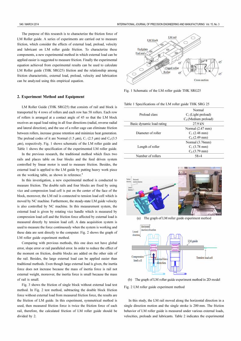
LM Roller Guide (THK SRG25) that consists of rail and block is
transported by 4 rows of rollers and each row has 58 rollers. Each row
of rollers is arranged at a contact angle of 45 so that the LM block
receives an equal load rating in all four directions (radial, reverse radial
and lateral direction), and the use of a roller cage can eliminate friction
between rollers, increase grease retention and minimize heat generation.
The preload codes of it are Normal (1.5 µm), C1 (2.5 µm) and C0 (3.5
µm), respectively. Fig. 1 shows schematic of the LM roller guide and
Table 1 shows the specification of the experimented LM roller guide.
In the previous research, the traditional method which fixes two
rails and places table on four blocks and the feed driven system
controlled by linear motor is used to measure friction. Besides, the
external load is applied to the LM guide by putting heavy work piece
on the working table, as shown in reference.4
In this investigation, a new experimental method is conducted to
measure friction. The double rails and four blocks are fixed by using
vice and compression load cell is put on the center of the face of the
block, moreover, the LM rail is connected to tension load cell which is
moved by NC machine. Furthermore, the steady-state LM guide velocity
is also controlled by NC machine. In this measurement system, the
external load is given by rotating vice handle which is measured by
compression load cell and the friction force affected by external load is
measured directly by tension load cell. A data acquisition system is
used to measure the force continuously when the system is working and
these data are sent directly to the computer. Fig. 2 shows the graph of
LM roller guide experiment method.
Comparing with previous methods, this one does not have global
error, slope error or rail paralleled error. In order to reduce the effect of
the moment on friction, double blocks are added on the other side of
the rail. Besides, the large external load can be applied easier than
traditional methods. Even though large external load is given, the inertia
force does not increase because the mass of inertia force is rail not
external weight, moreover, the inertia force is small because the mass
of rail is small.
Fig. 3 shows the friction of single block without external load test
method. In Fig. 2 test method, subtracting the double block friction
force without external load from measured friction force, the results are
the friction of LM guide. In this experiment, symmetrical method is
used, then measured friction force is twice the friction force of each
rail, therefore, the calculated friction of LM roller guide should be
divided by 2.
In this study, the LM rail moved along the horizontal direction in a
single direction motion and the single stroke is 200 mm. The friction
behavior of LM roller guide is measured under various external loads,
velocities, preloads and lubricants. Table 2 indicates the experimental
Fig. 1 Schematic of the LM roller guide THK SRG25
Table 1 Specifications of the LM roller guide THK SRG 25
Preload class
Normal
C1 (Light preload)
C0 (Medium preload)
Basic dynamic load rating 27.9 kN
Diameter of roller
Normal (2.47 mm)
C1 (2.48 mm)
C0 (2.49 mm)
Length of roller
Normal (3.76mm)
C1 (3.78 mm)
C0 (3.79 mm)
Number of rollers 58×4
Fig. 2 LM roller guide experiment method

INTERNATIONAL JOURNAL OF PRECISION ENGINEERING AND MANUFACTURING Vol. 15, No. 3 MARCH 2014 / 547
conditions and equipments.
3. Experimental Results
3.1 Relationship among external load, preload and friction
In order to study the effects of the load and preload on the friction
force, the friction force is measured for various loads. The external load
is changed from 1.5 kN to 10 kN, which is 5.3~35.8% of the basic
dynamic load rating. In this experiment, the velocity is 0.11 m/s,
kinematic viscosity is 99 mm2/s and three different preloads are used.
Fig. 4 shows how the friction force varied with respect to the external
load and preload. Selected experimental points are used to demonstrate
the effect; the results for combinations of different preloads are
indicated. It is noticed that the friction force increases as external load
increases, and friction force also increases as preload increases. The
slope of friction curve from Normal, C1 to C0 is decreasing, because the
deflection of LM bearing guide with a preload under a given load is
smaller, and the rigidity is much greater than that without a preload.10
Since an LM system makes rolling motion via its rolling elements
such as rollers between the raceways, its frictional coefficient is much
smaller than a sliding guide. The THK Company suggests the different
friction coefficients for different LM Roller Guides, and from THK
company catalog, the average coefficient of LM roller guide SRG
friction range is from 0.001 to 0.002.10
Friction coefficient, in general, has been determined as a function
normal force and friction force. Using this method, the average
coefficient of LM roller guide friction is calculated from Normal, C1
and C0. In Fig. 5, the results concerning the friction coefficient are
compared with friction coefficient reference diagram from THK
catalog. The reference diagram is drawn by calculating the average of
different types of the LM systems, preloads, velocities, temperatures
and so on.
As shown in Fig. 5, the friction coefficient has values between
0.001 and 0.0177. When the applied load ratio is smaller than 0.18, the
friction coefficient is decreasing large as the applied load ratio
increases. However, when the applied load ratio is larger than 0.18, the
friction coefficient decreases between 0.001 and 0.002. The value of
friction coefficient calculated from experiment results is the same as
the value of THK Company catalog.
Fig. 3 The graph of single block test method
Table 2 Experiment conditions and equipments
Travel distance 200 mm
External load From 1.5 to 10 kN
Velocity From 0.0017 to 0.13 m/s
AFE-CA Grease Kinematic
viscosity at 40oC99 mm2/s
AFA grease Kinematic
viscosity at 40oC25 mm2/s
Compression load cell CAS-Korea C1E-2TS 2000 kg
Tension load cell CAS-Korea CSBA-10LS 10 kg
Data logger Radian INC. SDL-350R
NC machine HYUNDAI-KIA machine KV 25
Fig. 4 Relationship among external load, preload and friction force
Fig. 5 Comparison of the calculated and friction coefficient reference
diagram from THK catalog

548 / MARCH 2014 INTERNATIONAL JOURNAL OF PRECISION ENGINEERING AND MANUFACTURING Vol. 15, No. 3
3.2 Relationship between velocity and friction
In order to investigate the effect of the velocity on the friction force,
the friction is measured at various constant velocities and different
preloads. In this experiment the single block test method is used which
has its velocities from 0.0017 m/s to 0.13 m/s and the kinematic viscosity
is 99 mm2/s.
In Fig. 6, a comparison of the results from different velocities and
preloads are illustrated. The results for this graph indicate that the
friction force takes a maximum value at very low velocity in three kinds
of preload. When the velocity is smaller than 0.005 m/s, the friction
force decreases exponentially with the increasing of velocity, which is
due to mixed lubrication.
The mixed lubrication can be defined as a friction contribution at
low velocities, which is decreasing exponentially, as shown in Fig. 7.
The Stribeck curve presents the relationship among friction coefficient,
kinematic viscosity, velocity and normal load. Regions I, II and III in
the Stribeck curve correspond to boundary lubrication, mixed lubrication
and hydrodynamic lubrication respectively. The mixed lubrication regime
refers to a combination of boundary lubrication with hydrodynamic
lubrication. Generally, the minimum friction coefficient appears in the
mixed lubrication regime (region II).11,12
In this regime, the two surfaces are partly separated, partly in contact.
As the speed increases, the metal-to-metal contact surface is reduced,
then, the friction force decreases. When the preload increases, the fluid
film thickness is further reduced and metal-to-metal contact become
stronger, and then friction force increases. Besides, the slope of friction
curve also becomes larger as the preload increases.
For velocities above 0.005 m/s, the friction force linearly increases
with increasing velocity due to hydrodynamic lubrication. In the
hydrodynamic lubrication friction regime where the viscous friction is
dominant, the dynamic viscosity of the fluid, the velocity and contact
area of the moving object determine the friction force to be overcome,
and the viscous friction force is assumed to be proportional to the
velocity.11 In addition, for three different preloads, the friction forces
increase as preload increases because the fluid film thickness becomes
thinner as the preload increases.
3.3 Relationship between lubricant and friction
In order to investigate the effect of lubricant on the friction force,
the friction force is measured under C1 preload without external load,
and the dynamic friction characteristics are studied under two viscosities
of grease (99 mm2/s and 25 mm2/s).
In Fig. 8, a comparison of the results from different greases is
illustrated. It can be seen from this graph that the friction force with high
kinematic viscosity is smaller than friction force with low kinematic
Fig. 6 Relationship between velocity and friction forceFig. 8 Relationship between lubricant and friction force
Fig. 7 Stribeck curve and regimes of lubrication (η: Kinematic
viscosity, P: Normal load and V: Velocity)
INTERNATIONAL JOURNAL OF PRECISION ENGINEERING AND MANUFACTURING Vol. 15, No. 3 MARCH 2014 / 549
viscosity when the velocity is smaller than 0.005 m/s. The drop-off in
friction is called the mixed lubrication, for low value of kinematic
viscosity fluid, fluid film thickness is reduced, then the friction force
with low viscosity makes metal-to-metal contact stronger, therefore, the
friction force with low kinematic viscosity is higher than friction force
with high kinematic viscosity. This phenomenon is also shown at mixed
lubrication curve in Fig. 7.
For velocities above 0.005 m/s, the friction force with low kinematic
viscosity is smaller than friction force with high kinematic viscosity
because of viscous friction. In viscous friction regime, a lower viscosity
decreases the fluid film thickness which will also decrease the friction
force, then for small value of kinematic viscosity, friction force is
small.
3.4 Relationship between velocity and friction vibration
The friction force is measured under Normal preload at various
velocities (0.0017, 0.003, 0.025 and 0.042 m/s) along horizontal motion
direction and the external load is zero.
Fig. 9 shows the friction force variations with time. It can be seen
that the magnitude of friction vibration decreases with the increase of
velocity, which is due to stick-slip behavior. The stick-slip phenomenon
is the spontaneous jerky motion that can occur while two objects are
sliding each other. However, the steady sliding motion is achieved,
without stick-slip behavior, as the velocity increases.14,15
In this experiment, the value of friction force is calculated from the
mean value of the kinematic friction curve.
4. Discussion
4.1 Experimental equation
In this experiment, the effects of velocity, external load, lubricant
and preload on the friction force are taken into account. The empirical
equation is composed of Coulomb friction, Stribeck effect and Viscous
friction which is to estimate the friction of LM roller guide, and the
factors include the external load, preload, velocity and lubricant.
Coulomb and Viscous friction are modeled as shown in Eqs. (1) and
(2).
(1)
(2)
The Stribeck effect force is considered using an exponential model
similar to the model proposed by Jeong:13
(3)
A Stribeck curve11 presenting the relationship among velocity,
kinematic viscosity and normal load can be obtained by summing up
the Coulomb friction, Viscous friction and Stribeck effect force.
Therefore, the frictional equation of LM roller guide THK SRG25
can be expressed as Eq. (4):
(4)
The values of k1, k2, µν, VSt, µSt and f0 cannot be known before an
experiment is carried out. Therefore, their values are determined by
experiment results. The values of k1, k2 are achieved from Fig. 4, and
the values of µν, VSt, µSt and f0 are achieved from Figs. 6 and 8. The
fCoulomb
k1
k2pc
–( )P 103–×=
fViscous
µνpcνV f
0+=
fStribeck
µSt
pc
ν----e
V
VSt
-------–
=
F k1
k2pc
–( )P 103–× p
cµννV
µSt
ν------e
V
VSt
-------–
+⎝ ⎠⎜ ⎟⎛ ⎞
f0
+ +=
Fig. 9 Friction vibration for different constant velocities
Fig. 10 Friction force simulations

550 / MARCH 2014 INTERNATIONAL JOURNAL OF PRECISION ENGINEERING AND MANUFACTURING Vol. 15, No. 3
experimental friction equation of LM roller guide THK SRG25 can be
changed as Eq. (5):
(5)
For three kinds of preload Normal, C1 and C0, the friction force F
in response to the external load, velocity and lubricant can be calculated
by Eq. (5), respectively. Fig. 10 shows the simulation results for different
velocities and external loads. In this case, kinematic viscosity is 99
mm2/s and Normal, C1 and C0 are calculated. As shown in Fig. 10, the
friction graph calculated from experimental friction equation is similar
trend to the graph of experiment results. If kinematic viscosity, external
load and velocity are changed, the value of friction force will be
changed.
4.2 Validation of the experimental equation
To validate the developed experimental equation in this paper, the
predictions from experimental equation are compared with experimental
data. The friction forces are measured at various velocities (0.008,
0.025, 0.042 and 0.075 m/s) along horizontal motion direction, external
loads (2, 4, 6 and 8 kN) and three different preloads (Normal, C1 and C0).
Fig. 11 plots the comparison between the friction force from
experimental Eq. (5) and those from experimental data. The maximum
difference between experiment values and prediction values are about
18.3%, 17.8% and 14% with respect to Normal, C1 and C0 preload,
respectively. Although the predicted values of friction force are
different from experimental friction force, the agreement is reasonable.
And the same trend that friction force increases with increasing
external load and velocity is observed.
5. Conclusion
In this paper, a new experiment method is conducted to measure
LM guide friction force. And the friction behavior of LM roller guide
THK SRG25 in response to the external load, velocity, preload and
lubrication is examined experimentally. The experimental result proves
that the friction force increases as the external load increases and the
value of friction coefficient decrease with the increase of external load.
When the velocity is smaller than 0.005 m/s, the friction force with high
kinematic viscosity is smaller than friction force with low kinematic
viscosity. However, for velocities above 0.005 m/s, the friction force
with high kinematic viscosity is higher than friction force with low
kinematic viscosity. Furthermore, when a preload is applied to increase
rigidity, the friction force also increases. Therefore, the friction force
increases as the preload increases.
The experimental friction equation of LM roller guide is achieved
for the calculation of friction force. For verification, the friction forces
predicted from the equation are compared with those from the additional
experiment data. It is found from comparison that there is a good
agreement between friction forces predicted from derived equation and
those from the experiment.
Therefore, the experimental friction equation can express the behavior
of LM roller guide THK SRG25, and the relationship among friction
characteristic, external load, preload, velocity and lubrication can be
analyzed using this empirical equation.
REFERENCES
1. Yi, Y. S., Kim, Y. Y., Choi, J. S., Yoo, J. H., Lee, D. J., and et al.,
“Dynamic Analysis of a Linear Motion Guide Having Rolling
Elements for Precision Positioning Devices,” Journal of Mechanical
Science and Technology, Vol. 22, No. 1, pp. 50-60, 2008.
2. Oiwa, T., “Friction Control using Ultrasonic Oscillation for Rolling-
Element Linear-Motion Guide,” Review of Scientific Instruments,
Vol. 77, No. 1, Page No. 016107, 2006.
F 0.315 0.03pc
–( )P 103–× p
c0.244νV
30
ν------e
V
0.01----------–
+⎝ ⎠⎜ ⎟⎛ ⎞
3+ +=
Fig. 11 Predicted and experimental friction forces for different
preloads

INTERNATIONAL JOURNAL OF PRECISION ENGINEERING AND MANUFACTURING Vol. 15, No. 3 MARCH 2014 / 551
3. Andersson, S., Soderberg, A., and Bjorklund S., “Friction models for
Sliding Dry, Boundary and Mixed Lubricated Contacts,” Tribology
International, Vol. 40, No. 4, pp. 580-587, 2007.
4. Fujita, T., Matsubara, A., and Yamazaki, K, “Experimental
Characterization of Disturbance Force in a Linear Drive System
with High-Precision Rolling Guideways,” International Journal of
Machine Tools and Manufacture, Vol. 51, No. 2, pp. 104-111, 2011.
5. Chen, J. S., Chen, K. C., Lai, Z. C., and Huang, Y. K., “Friction
Characterization and Compensation of a Linear-Motor Rolling Guide
Stage,” International Journal of Machine Tools and Manufacture,
Vol. 43, No. 9, pp. 905-915, 2003.
6. Kaneko, S., Sato, R., And Tsutsumi, M., “Mathematical Model of
Linear Motor Stage with Non-Linear Friction Characteristics,” Journal
of Advanced Mechanical Design, Systems, and Manufacturing, Vol.
2, No. 4, pp. 675-684, 2008.
7. Al-Bender, F. and Symens, W., “Characterization of Frictional
Hysteresis in Ball-Bearing Guideways,” Wear, Vol. 258, No. 11-12,
pp. 1630-1642, 2005.
8. Lin, T. W. and Modafe, A., “Characterization of Dynamic Friction in
MEMS-Based Microball Bearings,” IEEE Transactions on
Instrumentation and Measurement, Vol. 53, No. 3, pp. 839-846,
2004.
9. Khim, G. H., Park, C. H., Shamoto, E., and Kim, S. W., “Prediction
and Compensation of Motion Accuracy in a Linear Motion Bearing
Table,” Precision Engineering, Vol. 35, No. 3, pp. 393-399, 2011.
10. THK Co., Ltd., THK Linear Motion System Catalog, 2008.
11. Maru, M. M. and Tanaka, D. K., “Consideration of Stribeck Diagram
Parameters in the Investigation on Wear and Friction Behavior in
Lubricated Sliding,” Journal of the Brazilian Society of Mechanical
Sciences and Engineering, Vol. 29, No. 1, pp. 55-62, 2007.
12. Lee, C. G., Hwang, Y. J., Choi, Y. M., Lee, J. K., Choi, C., and Oh,
J. W., “A Study on the Tribological Characteristics of Graphite Nano
Lubricants,” Int. J. Precis. Eng. Manuf., Vol. 10, No. 1, pp. 85-90,
2009.
13. Jeong, Y. H., Min, B. K., Cho, D. W., and Lee, S. J., “Motor Current
Prediction of a Machine Tool Feed Drive Using a Component-based
Simulation Model,” Int. J. Precis. Eng. Manuf., Vol. 11, No.4, pp.
597-606, 2010.
14. Kang, J. Y., Krousgrill, C. M., and Sadeghi, F., “Oscillation Pattern
of Stick-Slip Vibrations,” International Journal of Non-Linear
Mechanics, Vol. 44, No. 7, pp. 820-828, 2009.
15. Neis, P. D., Baets, P. D., Ost, W., Delgado, Y. P., Loccufier, M., and
et al., “Investigation of the Dynamic Response in a Dry Friction
Process using a Rotating Stick-Slip Tester,” Wear, Vol. 271, No. 9-
10, pp. 2640-2650, 2011.