
FREQUENCY RECONFIGURABLE TAPERED SLOT...
36
FREQUENCY RECONFIGURABLE TAPERED SLOT ANTENNAS FOR WIDEBAND NARROWBAND AND MULTIBAND APPLICATIONS SAHAR CHAGHARVAND UNIVERSITI TEKNOLOGI MALAYSIA
Transcript of FREQUENCY RECONFIGURABLE TAPERED SLOT...

FREQUENCY RECONFIGURABLE TAPERED SLOT ANTENNAS FOR
WIDEBAND NARROWBAND AND MULTIBAND APPLICATIONS
SAHAR CHAGHARVAND
UNIVERSITI TEKNOLOGI MALAYSIA

FREQUENCY RECONFIGURABLE TAPERED SLOT ANTENNAS FOR
WIDEBAND NARROWBAND AND MULTIBAND APPLICATIONS
SAHAR CHAGHARVAND
A thesis submitted in fulfilment of the
requirements for the award of the degree of
Doctor of Philosophy (Electrical Engineering)
Faculty of Electrical Engineering
Universiti Teknologi Malaysia
MARCH, 2016

iii
To my beloved parents: “Shamsedin Chagharvand & Farah Heidari” and my beloved brothers “Ali & Amin and Farshad”

iv
ACKNOWLEDGEMENT
First of all, praise to Allah for his kindness to let complete this thesis. In the
course of this research, I was in contact with many people, researchers,
academicians, and practitioners. They have contributed towards my understanding
and thoughts throughout my research. In particular, I would like to express my
gratitude to my supervisor, Dr. Mohamad Rijal Bin Hamid for his guidance, advices,
patients, encouragements and supports to complete this work. I would also like to
thank my co-supervisor, Assoc. Prof. Dr. Muhammad Ramlee Bin Kamarudin for his
precious advices, valuable comments and support.
I am extremely grateful to my family for their generous support throughout
my PhD, and indeed the whole of my life. Their wisdom, kindness and excellent
advice have made me who I am today and I hope that I have made them proud.
Thanks Dad for believing in me and thanks Mom for your infinite love. Thanks to
my brothers for all the fun and laughter they bring to my life. I would also like to
thank to Microwave Advanced Laboratory and the people in P18, FKE who had
helped me for measurement and fabrication of my designs during my study.
Finally, I would like to thank all the persons who are not mentioned here, but
have been a great help during my period of study.
v
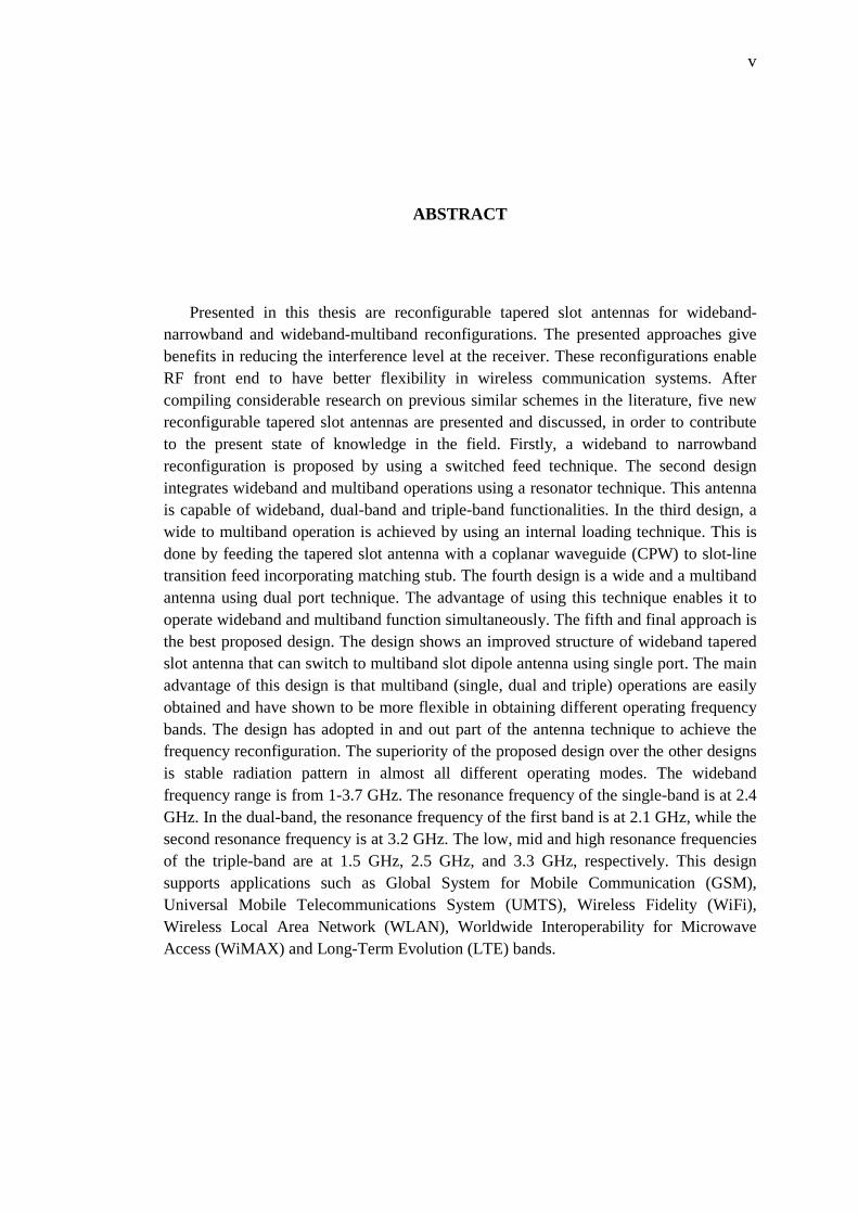
ABSTRACT
Presented in this thesis are reconfigurable tapered slot antennas for wideband-narrowband and wideband-multiband reconfigurations. The presented approaches give benefits in reducing the interference level at the receiver. These reconfigurations enable RF front end to have better flexibility in wireless communication systems. After compiling considerable research on previous similar schemes in the literature, five new reconfigurable tapered slot antennas are presented and discussed, in order to contribute to the present state of knowledge in the field. Firstly, a wideband to narrowband reconfiguration is proposed by using a switched feed technique. The second design integrates wideband and multiband operations using a resonator technique. This antenna is capable of wideband, dual-band and triple-band functionalities. In the third design, a wide to multiband operation is achieved by using an internal loading technique. This is done by feeding the tapered slot antenna with a coplanar waveguide (CPW) to slot-line transition feed incorporating matching stub. The fourth design is a wide and a multiband antenna using dual port technique. The advantage of using this technique enables it to operate wideband and multiband function simultaneously. The fifth and final approach is the best proposed design. The design shows an improved structure of wideband tapered slot antenna that can switch to multiband slot dipole antenna using single port. The main advantage of this design is that multiband (single, dual and triple) operations are easily obtained and have shown to be more flexible in obtaining different operating frequency bands. The design has adopted in and out part of the antenna technique to achieve the frequency reconfiguration. The superiority of the proposed design over the other designs is stable radiation pattern in almost all different operating modes. The wideband frequency range is from 1-3.7 GHz. The resonance frequency of the single-band is at 2.4 GHz. In the dual-band, the resonance frequency of the first band is at 2.1 GHz, while the second resonance frequency is at 3.2 GHz. The low, mid and high resonance frequencies of the triple-band are at 1.5 GHz, 2.5 GHz, and 3.3 GHz, respectively. This design supports applications such as Global System for Mobile Communication (GSM), Universal Mobile Telecommunications System (UMTS), Wireless Fidelity (WiFi), Wireless Local Area Network (WLAN), Worldwide Interoperability for Microwave Access (WiMAX) and Long-Term Evolution (LTE) bands.
vi
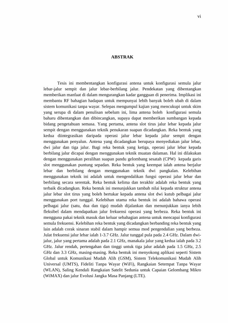
ABSTRAK
Tesis ini membentangkan konfigurasi antena untuk konfigurasi semula jalur lebar-jalur sempit dan jalur lebar-berbilang jalur. Pendekatan yang dibentangkan memberikan manfaat di dalam mengurangkan kadar gangguan di penerima. Implikasi ini membantu RF bahagian hadapan untuk mempunyai lebih banyak boleh ubah di dalam sistem komunikasi tanpa wayar. Selepas mengumpul kajian yang mencukupi untuk skim yang serupa di dalam penulisan sebelum ini, lima antena boleh konfigurasi semula baharu dibentangkan dan dibincangkan, supaya dapat memberikan sumbangan kepada bidang pengetahuan semasa. Yang pertama, antena slot tirus jalur lebar kepada jalur sempit dengan menggunakan teknik penukaran suapan dicadangkan. Reka bentuk yang kedua diintegrasikan daripada operasi jalur lebar kepada jalur sempit dengan menggunakan penyalun. Antena yang dicadangkan berupaya menyediakan jalur lebar, dwi jalur dan tiga jalur. Bagi reka bentuk yang ketiga, operasi jalur lebar kepada berbilang jalur dicapai dengan menggunakan teknik muatan dalaman. Hal ini dilakukan dengan menggunakan peralihan suapan pandu gelombang sesatah (CPW) kepada garis slot menggunakan puntung sepadan. Reka bentuk yang keempat ialah antena berjalur lebar dan berbilang dengan menggunakan teknik dwi pangkalan. Kelebihan menggunakan teknik ini adalah untuk mengendalikan fungsi operasi jalur lebar dan berbilang secara serentak. Reka bentuk kelima dan terakhir adalah reka bentuk yang terbaik dicadangkan. Reka bentuk ini menunjukkan tambah nilai kepada struktur antena jalur lebar slot tirus yang boleh bertukar kepada antena slot dwi kutub pelbagai jalur menggunakan port tunggal. Kelebihan utama reka bentuk ini adalah bahawa operasi pelbagai jalur (satu, dua dan tiga) mudah dijalankan dan menunjukkan ianya lebih fleksibel dalam mendapatkan jalur frekuensi operasi yang berbeza. Reka bentuk ini mengguna pakai teknik masuk dan keluar sebahagian antena untuk mencapai konfigurasi semula frekuensi. Kelebihan reka bentuk yang dicadangkan berbanding reka bentuk yang lain adalah corak sinaran stabil dalam hampir semua mod pengendalian yang berbeza. Julat frekuensi jalur lebar ialah 1-3.7 GHz. Jalur tunggal pula pada 2.4 GHz. Dalam dwi-jalur, jalur yang pertama adalah pada 2.1 GHz, manakala jalur yang kedua ialah pada 3.2 GHz. Jalur rendah, pertengahan dan tinggi untuk tiga jalur adalah pada 1.5 GHz, 2.5 GHz dan 3.3 GHz, masing-masing. Reka bentuk ini menyokong aplikasi seperti Sistem Global untuk Komunikasi Mudah Alih (GSM), Sistem Telekomunikasi Mudah Alih Universal (UMTS), Fideliti Tanpa Wayar (WiFi), Rangkaian Setempat Tanpa Wayar (WLAN), Saling Kendali Rangkaian Satelit Sedunia untuk Capaian Gelombang Mikro (WiMAX) dan jalur Evolusi Jangka Masa Panjang (LTE).

vii
TABLE OF CONTENTS
CHAPTER TITLE PAGE
DECLARATION ii
DEDICATION iii
ACKNOWLEDGEMENT iv
ABSTRACT v
ABSTRAK vi
TABLE OF CONTENTS vii
LIST OF TABLES xi
LIST OF FIGURES xiii
LIST OF SYMBOLS xx
LIST OF ABBREVIATIONS xxi
LIST OF APPENDICES xxii
1 INTRODUCTION 1
1.1 Introduction 1
1.2 Problem Statement 2
1.3 Research Objectives 3
1.4 Scope of Research 3
1.5 Outline of Thesis 4
2 LITERATURE REVIEW 7
2.1 Introduction 7
2.2 Tapered Slot Antenna 8
2.2.1 Microstrip to Slot-line Transition Feed 10
2.2.2 CPW to Slot-line Transition Feed 13

viii
2.2.2.1 Delay Line 13
2.2.2.2 Matching Stub 17
2.2.3 Antipodal Feed 24
2.3 Frequency Reconfigurable Antennas 28
2.3.1 Frequency Reconfigurable Technique 29
2.3.1.1 Switched Feed Technique 29
2.3.1.2 Resonator Technique 31
2.3.1.3 Loading Technique 39
2.3.1.4 Dual Port Technique 45
2.3.1.5 Switching In and Out Part of the Antenna Technique 47
2.3.2 Reconfigurable Tapered Slot Antenna 49
2.4 RF Switches 58
2.4.1 PIN Diode Switches 59
2.4.2 MEMs Switches 61
2.4.3 FET Switches 62
2.5 Summary 63
3 RESEARCH METHODOLOGY 64
3.1 Introduction 64
3.2 Methodology 66
3.2.1 Design and Simulation (Stage 2) 66 3.2.2 Fabrication and Measurement (Stage 3) 70
3.3 Summary 75
4 FREQUENCY RECONFIGURABLE ANTENNA USING A SWITCHED FEED TECHNIQUE 76
4.1 Introduction 76
4.2 Bandwidth Reconfigurable Tapered Slot Antenna 76
4.2.1 Wideband Antenna Design 77
4.2.2 Narrowband Antenna Design 80
4.2.3 Bandwidth Control Antenna Design 84
4.2.4 Measurement and Validation of Bandwidth Control Antenna 87

ix
4.3 Frequency Switchable Tapered Slot Antenna 95
4.3.1 Narrowband Antenna Design 95
4.3.1.1 Technique 1 95
4.3.1.2 Technique 2 96
4.3.2 Wideband-Narrowband Reconfigurable Tapered Slot Antenna 100
4.3.3 Measurement and Validation 104
4.4 Summary 113
5 FREQUENCY RECONFIGURABLE ANTENNA USING STOP- BAND FILTERING TECHNIQUE 114
5.1 Introduction 114
5.2 Antenna Design 115
5.3 Parametric Study on Resonators 119
5.4 Measurement and Validation 126
5.5 Summary 133
6 FREQUENCY RECONFIGURABLE ANTENNA USING INTERNAL LOADING TECHNIQUE 134
6.1 Introduction 134
6.2 Wide and Multi-band Reconfigurable Tapered
Slot Antenna with CPW to Slot-line transition Feed Incorporating Matching Stub 135
6.3 Antenna Design 135
6.3.1 Wideband Antenna Design 135
6.3.2 Narrowband Antenna Design 139
6.3.3 Proposed Design 141
6.4 Measurement and Validation 148
6.5 Summary 157
7 AN INTEGRATED WIDEBAND TAPERED SLOT ANTENNA AND NARROWBAND SLOT DIPOLE ANTENNA 159
7.1 Introduction 159
7.2 A dual Port Antenna for Wide and Narrowband Applications 160

x
7.2.1 Wideband Antenna Design 160
7.2.2 Narrowband Antenna Design 161
7.2.3 Combination of Wideband and Narrowband Operations 168
7.3 Measurement and Validation 171
7.4 Switchable Slot Dipole to Tapered Slot Antenna Design and Configuration 180
7.4.1 Narrowband Antenna Design 181
7.4.2 Wideband Antenna Design 186
7.4.3 Wide to Narrowband Operation Switching 188
7.5 Measurement and Validation 190
7.6 Critical Analysis 200
7.7 Summary 202
8 CONCLUSIONS AND FUTURE WORK 204
8.1 Conclusions 204
8.1.1 Switched Feed Technique (Technique 1) 204
8.1.2 Band-Stop Resonator Technique (Technique 2) 205
8.1.3 Combined Band-Stop Resonator and
Internal Loading Technique (Technique 3) 206
8.1.4 Combined Wideband and Narrowband
Antennas Using Dual Port Technique (Technique 4) 206
8.1.5 Switching In and Out Part of the Antenna Technique (Technique 5) 207
8.2 Contribution to Existing Knowledge From the Research 207
8.3 Future Work 208
8.3.1 Introducing Band-Notch Operation 208
8.3.2 Improving Simulation Results 209
8.3.3 Application of MEMS Switches for High Frequency 210
8.3.4 Improving the Fabrication Accuracy 210

xi
REFERENCES 211
Appendices A-E 218-233

xii
LIST OF TABLES
TABLE NO. TITLE PAGE
2.1 Comparison between Tapered Slot Antennas 57
3.1 Material specification of the proposed antennas 69
3.2 Design specification of the proposed antennas 69
3.3 Radiation pattern measurement steps 74
4.1 Optimized design parameters and values of proposed antenna 86
4.2 Switches state and different modes 88
4.3 Simulated and measured gains 94
4.4 Optimized design parameters and values of proposed antenna
103
4.5 Switch states of the proposed antenna 104
4.6 Simulated and measured gains of mode 1 112 4.7 Simulated and measured gains 112
5.1 Parameters values of proposed antenna 115
5.2 Different states of the switches and corresponding bands 119
5.3 Measured gain of the proposed antenna 129
6.1 Optimized design parameters and values of proposed antenna 163
6.2 Switches state and different modes 147
6.3 Measured antenna gain in mode1 157
6.4 Simulated and measured antenna gain in all modes 157
7.1 Antenna dimensions 170 7.2 Different states of the PIN diodes and corresponding
bands 171
7.3 Gain of single-band mode 180

xiii
7.4 Configuration of PIN diode switches 190
7.5 Gain in wideband mode 200
7.6 Gain in dual-band mode 200
7.7 Gain in triple-band mode 200
7.8 Comparision between proposed designs 201
xiv
LIST OF FIGURES
FIGURE NO. TITLE PAGE
2.1 Antenna geometry 11
2.2 Antenna geometry 11
2.3 Antenna geometry 12
2.4 The simulated and measured responses of VSWR of the antenna 13
2.5 Configuration of tapered slot antenna 14
2.6 Simulated and measured return loss 15
2.7 Electric field distribution near wide slot transition 16
2.8 Configuration of the antenna 16
2.9 Simulated and measured VSWR of the presented structure 17
2.10 Antenna geometry 18
2.11 Simulated and measured return losses 19
2.12 The CPW to slot-line transition 20
2.13 Simulated and measured VSWR for three modes 21
2.14 Antenna structures 22
2.15 Simulated axial ratio and return losses 23
2.16 Antenna structure 24
2.17 Return loss of the antenna 25
2.18 Configuration of the presented design 25
2.19 Simulated return loss of different modes 26
2.20 Configuration of the antenna 27
2.21 Configuration of the antenna 30
2.22 Simulated and measured return loss 31
2.23 Geometry of the designed antenna 32

xv
2.24 Geometry of the designed antenna 33
2.25 Geometry of the antenna 33
2.26 Geometry of the antenna 34
2.27 Geometry of the antenna 36
2.28 Geometry of the antenna 37
2.29 Geometry of the antenna 37
2.30 Geometry of the antenna 38
2.31 a) Geometry of the antenna b) Tuning circuitry 40
2.32 Measured return loss 40
2.33 Simulated input impedance 41
2.34 a) MEMS switched PIFA and PCB b) MEMS switched PIFA circuit 42
2.35 Measured S11 43
2.36 Geometry of the antenna 44
2.37 Geometry of the antenna 44
2.38 Antenna geometry 45
2.39 Antenna structure 46
2.40 Integrated wide and narrowband monopole 47
2.41 Configuration of the antenna based on mm 48
2.42 Configuration of the antenna 49
2.43 Measured return loss of the antenna 50
2.44 Antenna geometry 50
2.45 Simulated and measured return loss of the antenna 51
2.46 Antenna geometry 51
2.47 Simulated and measured return losses of the presented antenna 52
2.48 Structure of the reconfigured antenna 53
2.49 Simulated and measured reflection coefficient 54
2.50 Reconfigured antenna 55
2.51 Configuration of the antenna 56
2.52 Simulated S11 and realized gain of the presented design 56
2.53 PIN diode circuit diagram when: a) forward biased b) reverse biased 59
2.54 PIN diode BAR50-02V 60
xvi
2.55 Frequency reconfigurable circularly polarized patch antenna by integrating MEMS switches 61
2.56 Simulated and measured reflection coefficients of the antenna 62
3.1 Research methodology flow chart 65
3.2 Copper strip performance 66
3.3 Structure of the proposed antenna 67
3.4 Discrete port 68
3.5 Circuit simulation of PIN diode using CST software 68
3.6 Return loss measurement 71
3.7 Radiation pattern and gain measurement layout 72
3.8 Radiation pattern measurement system 72
3.9 a) DC power supply b) biasing to the antenna 73
3.10 DC blocker 75
4.1 Antenna structure 80
4.2 Simulated S11 of wideband operation 80
4.3 Analysis of the proposed antenna 82
4.4 S11 of the antenna 83
4.5 Structure of the proposed tapered slot antenna 85
4.6 a) Structure of the feed-line tapered slot antenna b) Topology of the CPW to slot-line 85
4.7 Photograph of the proposed tapered slot antenna 88
4.8 Simulated and measured reflection coefficients for mode 1 89
4.9 Simulated and measured reflection coefficient for mode 2 89
4.10 Simulated and measured reflection coefficient for mode 3 90
4.11 Simulated and measured reflection coefficient for mode 2 in ideal case 90
4.12 Simulated reflection coefficients for all modes 91
4.13 Measured reflection coefficients for all modes 91
4.14 Simulated and measured radiation patterns 93
4.15 3D simulated radiation patterns: a) mode 1 b) mode 2 c) mode 3 94
4.16 Simulated results of the analysis of the delay line, L2=18 mm, varying L1 96

xvii
4.17 Structure of the feed-line 97
4.18 Simulated results of the analysis of the delay line when the rectangular is decoupled 99
4.19 Superimposed simulated radiation patterns for techniques 1 and 2 99
4.20 Structure of the proposed tapered slot antenna 101
4.21 a) topology of the switches b) wideband (CPW to slot-line transition feed) C) narrowband mode 3 (slot-line feed) d) narrowband mode 5 (slot-line feed) 101
4.22 The fabricated antenna structure 102
4.23 Simulated and measured reflection coefficient magnitudes of mode 1 104
4.24 Simulated and measured reflection coefficient magnitudes for mode 2 106
4.25 Simulated and measured reflection coefficient magnitudes for mode 3 106
4.26 Simulated and measured reflection coefficient magnitudes for mode 4 107
4.27 Simulated and measured reflection coefficient magnitudes for mode 5 107
4.28 Simulated reflection coefficient magnitudes for all modes 108
4.29 Measured reflection coefficient magnitudes for all modes 108
4.30 Simulated and measured radiation patterns of mode 1 109
4.31 Simulated and measured radiation patterns 110
5.1 Geometry of proposed TSA 112
5.2 Presented quarter wavelength resonator 115
5.3 Current distributions of the proposed antenna at wideband operation 116
5.4 S-parameters 118
5.5 S-parameter of T-shaped resonator 122
5.6 S-parameters of varying rectangular resonator at different locations 123
5.7 S-parameters of varying T-shaped at same location 123
5.8 Simulated reflection coefficient magnitude of dual-band 124
5.9 S-parameters of: a) longer rectangular b) shorter
rectangular 125

xviii
5.10 Simulated reflection coefficient magnitude a) dual-band b) triple-band 125
5.11 Photograph of the proposed TSA 126
5.12 Simulated and measured reflection coefficient magnitudes of wideband operation 127
5.13 Simulated and measured reflection coefficient magnitudes of dual-band operation 127
5.14 Simulated and measured reflection coefficient magnitudes of triple-band operation 128
5.15 Simulated and measured radiation patterns at 2 GHz 130
5.16 Simulated and measured radiation patterns of wideband 131
5.17 Simulated and measured radiation patterns 132
5.18 3D simulated radiation patterns at 2 GHz 133
6.1 Antenna Structure 136
6.2 Simulated return loss of wideband operation 136
6.3 Geometry of a shunt connected matching stub 137
6.4 Antenna structure 139
6.5 Simulated reflection coefficient, with and without radial stub 140
6.6 Geometry and simulated S21 resonator slits 141
6.7 a) Structure of proposed tapered slot antenna, b) a zoom-in on the feed area 142
6.8 Simulated and measured reflection coefficient for mode 2 143
6.9 Simulated and measured reflection coefficient for mode 3 143
6.10 Simulated and measured reflection coefficient for mode 4 144
6.11 Simulated and measured reflection coefficient for mode 5 144
6.12 Simulated S11 of varying rectangular slits 145
6.13 The input impedance of single-band operation, mode 2 146
6.14 The superimposed radiation patterns of single-band operation, mode 2 147
6.15 Photograph of the proposed tapered slot antenna 149
6.16 Simulated and measured reflection coefficient for mode1 149
6.17 Simulated reflection coefficient for all modes 149

xix
6.18 Measured reflection coefficient for all modes 150
6.19 Simulated and measured radiation patterns 152
6.20 Simulated and measured radiation patterns of wideband operation of mode 1 153
6.21 Simulated and measured radiation patterns of dual-band operations 154
6.22 Simulated and measured radiation patterns of triple-band operation 155
6.23 3D simulated radiation patterns 156
6.24 Measured gain of wideband mode 157
7.1 Antenna structure 161
7.2 Simulated return loss of wideband operation 161
7.3 Slot dipole configurations with simulated reflection coefficient of narrowband antenna 164
7.4 a) Voltage distribution in a dipole antenna b) Current
distribution in a slot dipole antenna 165
7.5 Current distributions of (a) without slit (b) with slit and their corresponding S11 165
7.6 Current distributions of varying the slit position and their corresponding S11 167
7.7 The input impedances 168
7.8 Configuration of the proposed antenna 169
7.9 Prototype of the proposed antenna 170
7.10 Simulated and measured S11 of port 1 171
7.11 Simulated and measured S11 of port 2 172
7.12 Simulated and measured S21 174
7.13 Simulated and measured radiation patterns of port 1 176
7.14 Simulated and measured radiation patterns of port 2 178
7.15 3D simulated radiation patterns of port 1 180
7.16 Different types of opening slot 182
7.17 Simulated radiation pattern of dual-band mode at φ = 90 183
7.18 Current distributions of dual-band mode at 2.1 GHz 184
7.19 Simulated S11 186
7.20 Geometry of the proposed antenna 187
7.21 Simulated reflection coefficient of wideband mode 187
7.22 Geometry of the proposed antenna 189

xx
7.23 Structure of the antenna feed line: P1 to P5 show the diodes location 189
7.24 Structure of the PIN diode switches biasing 190
7.25 Simulated and measured reflection coefficient of wideband 191
7.26 Photograph of the proposed antenna 192
7.27 Simulated and measured reflection coefficient of single-band 192
7.28 Simulated and measured reflection coefficient of dual-band 193
7.29 Simulated and measured reflection coefficient of triple-band 193
7.30 Simulated and measured reflection coefficient of narrowband modes using s2p file for ON state and ideal case for OFF state 194
7.31 Simulated and measured co and cross-polar radiation patterns 197
7.32 Simulated and measured radiation patterns of wideband 198
7.33 Simulated and measured radiation patterns 199
8.1 Configuration of the antenna 209
8.2 Simulation of reflection coefficient magnitude 209
xxi
LIST OF ABBREVIATIONS
CPW - Coplanar Waveguide
CST - Computer Simulation Technology
DC - Direct Current
EM - Electromagnetic
FR4 - Fire Retardant Type 4
FIT - Finite Integration Technique
GPS - Global Positioning System
GSM - Global System for Mobile Communication
Gas FET - Gallium Arsenide Field Effect Transistor
LTE - Long-Term Evolution
MEMS - Micro Electro Mechanical System
PIN Diode - Positive Intrinsic Negative Diode
PIFA - Planar Inverted F Antenna
Q-factor - Quality factor
RMTSA - Reconfigurable Multiband Tapered Slot Antenna
SMA - Sub Miniture Version A
SMD - Surface Mounted Devices
TSA - Tapered Slot Antenna
UV - Ultra Violet
UMTS - Universal Mobile Telecommunications System
VNA - Vector Network Analyzer
WiFi - Wireless Fidelity
WiMAX - Worldwide Interoperability for Microwave Access
WLAN - Wireless Local Area Network

xxii
LIST OF SYMBOLS
K - Ratio
ji - Bessel Ni - Neumann
BW - Bandwidth
fr - Reference frequency
Q - Q-factor
C - Capacitance
Ɛ0 - Permittivity of free space
A - Surface area d - Distance between the capacitance plates λg - Guide wavelength λ0 - Free space wavelength Ɛr - Relative permittivity ɵu - Upper angular width ɵl - Lower angular width HPBW - Half power beam width L - Total length of slot arm f - Frequency

xxiii
APPENDICES
APPENDIX TITLE PAGE
A List of Publications 218
B Fabrication Process 219
C BAR 50-0V Data Sheet 220
D Radiation Patterns of Dipole Antenna in Single Port 231
E Calculations of Wavelength in C- and T-shaped Resonators 233
CHAPTER 1
INTRODUCTION
1.1 Introduction
The rapid expansion of electronics and wireless communication systems has
created multiple wireless applications and standards. Reconfigurable antenna is
proposed in order to provide multi-functionality for wireless communication
systems. The fundamental characteristics such as operating frequency, radiation
pattern and polarization are reconfigured to accommodate modifications in the
operating arrangement. The most important advantages of reconfigurable antenna
over typical antenna are: a) the ability to tune the antenna operating frequency over a
band, b) filtering capability to remove interfering signals and c) their ability to tune
the antenna in a new operating environment [1].
After the introduction of cognitive radio systems, interest in reconfigurable
antennas, wideband and multiband antennas has considerably increased. Two types
of architecture have been proposed in cognitive radio systems. The first one uses a
single wideband antenna for both sensing of the spectrum and communication link.
The second uses a wideband antenna for spectrum sensing and a reconfigurable
antenna for the communication link [2]. Reconfigurable antennas offer significant
advantages for wireless communication systems compared to wideband and
multiband antennas, such as compactness and flexibility. A considerable number of
reconfigurable antennas with narrowband switching capabilities have been discussed
2
in [3-15]. Wideband-to-narrowband reconfigurable antennas [16-18], providing
multi-functionality, have great potential to be used in cognitive radio systems. In [19-
21], wideband-to-multiband reconfigurable antennas were presented. In cognitive
radio systems, a reconfigurable antenna is required for the communication link [22-
24].
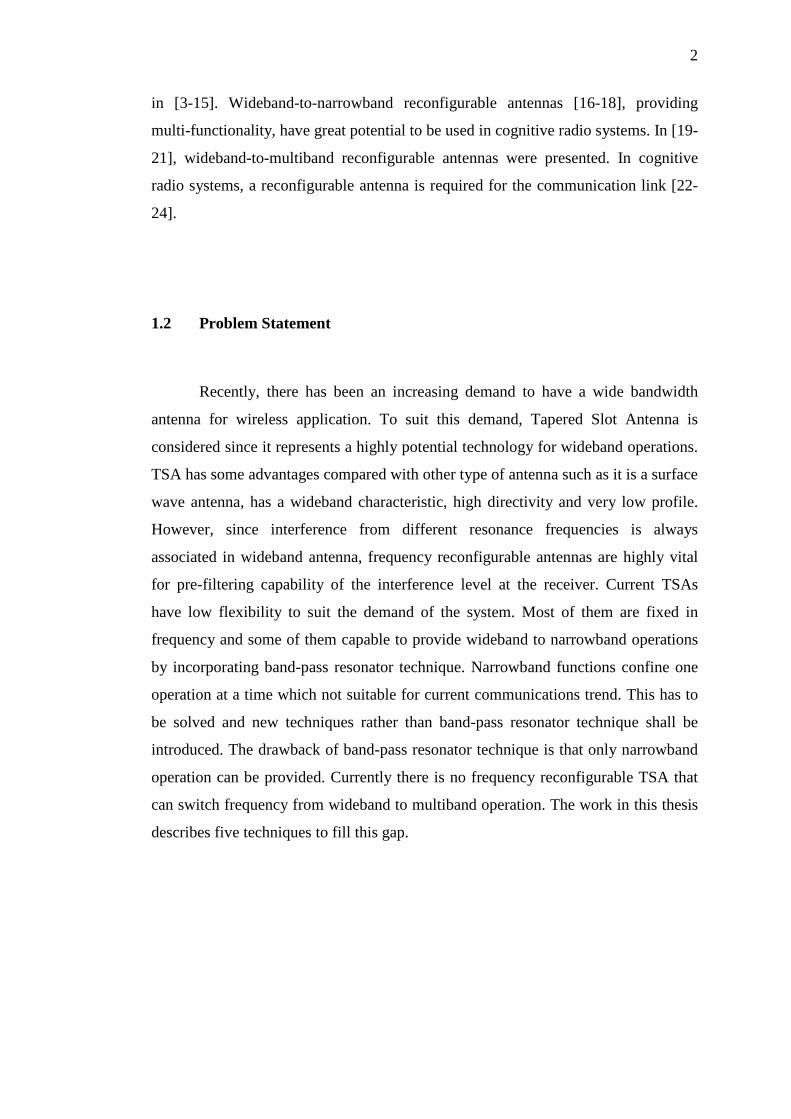
1.2 Problem Statement
Recently, there has been an increasing demand to have a wide bandwidth
antenna for wireless application. To suit this demand, Tapered Slot Antenna is
considered since it represents a highly potential technology for wideband operations.
TSA has some advantages compared with other type of antenna such as it is a surface
wave antenna, has a wideband characteristic, high directivity and very low profile.
However, since interference from different resonance frequencies is always
associated in wideband antenna, frequency reconfigurable antennas are highly vital
for pre-filtering capability of the interference level at the receiver. Current TSAs
have low flexibility to suit the demand of the system. Most of them are fixed in
frequency and some of them capable to provide wideband to narrowband operations
by incorporating band-pass resonator technique. Narrowband functions confine one
operation at a time which not suitable for current communications trend. This has to
be solved and new techniques rather than band-pass resonator technique shall be
introduced. The drawback of band-pass resonator technique is that only narrowband
operation can be provided. Currently there is no frequency reconfigurable TSA that
can switch frequency from wideband to multiband operation. The work in this thesis
describes five techniques to fill this gap.

3
1.3 Research Objectives
The main objectives of this research are as follows:
i. To incorporate a narrowband function and control the bandwidth of a
wideband tapered slot antenna
ii. To add the multiband function into a wideband tapered slot antenna
iii. To employ several reconfiguration techniques; namely switched feed, band-
stop resonator, internal loading, and switching in and out part of the antenna
iv. To combine wideband tapered slot antenna and slot dipole antenna using
single and dual ports
1.4 Scope of Research
The scope for each objective is presented below, within anticipated border
lines to support the aim of this research.
The aim of this work is to incorporate narrowband and multiband functions
into a wideband tapered slot antenna. Therefore, it is necessary to study and
understand the fundamental behavior of the tapered slot antenna. There are several
types of tapered slot antenna which are categorized based on their feeding technique:
namely microstrip to slot-line transition feed, CPW to slot-line transition feed
incorporating delay line, CPW to slot-line transition feed incorporating matching
stub and antipodal feed network. However, this work will only focus on CPW to slot-
line transition feeding structures due to the ease of fabrication and simple
manipulation of the delay line and matching stub so that wideband to multiband
operation is achieved.
There are several techniques which can be adopted to achieve frequency
reconfigurability. However, the most common technique (and possibly the only
4
technique used so far in a tapered slot antenna) employs band-pass resonators. To fill
this gap therefore, various techniques will be proposed and used as follows: switched
feed, band-stop resonator, internal loading, dual port and switching in and out part of
the antenna. In addition, a dual ports structure - with a combination of slot dipole and
tapered slot antennas - will also be developed. Therefore, it is also necessary to study
and understand the fundamental behavior of the slot dipole antenna.
To achieve frequency reconfiguration electronically, RF switches are used.
There are various types of RF switches; such as PIN diodes, MEMS and FETs. In
this work, all proposed antennas were developed using PIN diode switches, since
they have strategic advantages over MEMS and FETs - such as fast switching
speeds, and are easy to fabricate. Moreover, they are readily available on the market.
Since the PIN diode switches used in this work cover the range of frequencies up to 6
GHz, all the proposed antennas operating frequencies are therefore designed within
this limit. All numerical solutions are obtained using CST's 3D simulator.
1.5 Outline of Thesis
In Chapter 1, a brief introduction is given on frequency reconfigurable
antenna. This is followed by motivation for the work, the scope of the research and
the research objectives.
Chapter 2 presents the backgrounds of the frequency reconfigurable antenna
and tapered slot antenna. Previous studies on frequency reconfigurable antennas,
including narrowband-to-narrowband, wideband-to-narrowband and wideband-to-
multiband are then discussed and summarized.
Chapter 3 describes the methodology of the research. The flow of the studies
is presented, and the main two phases of the study are reported. The designs and
5
simulations are explained in the first phase of study in detail. The fabrication and
measurement of the antenna are fully discussed in the second phase of the study.
Chapter 4 presents a wide-to-narrowband frequency reconfigurable antenna.
A frequency reconfigurable tapered slot antenna, with a bandwidth control and a
switchable frequency band characteristic, is discussed. A switched feed technique is
then introduced, and the placement of switches on the delay line is discussed.
Chapter 5 presents a reconfigurable multiband tapered slot antenna using a
band-stop resonator technique. The antenna consists of a T and C-shaped resonator to
produce frequency reconfiguration. Switches are placed on the edge of the V opening
slot to produce three different operations. The designed antenna is suitable to be used
as a base station antenna for cognitive radio systems.
Chapter 6 describes a wide-to-multiband frequency reconfigurable slot-line
feed tapered slot antenna. The proposed antenna consists of two rectangular slits and
a cone shaped matching stub. An internal loading technique is used in designing this
antenna.
Chapter 7 initiates the combination of two antennas into a single antenna, in
order to improve the system space. A dual port antenna for both wide and
narrowband applications is discussed. The proposed antenna system consists of two
antennas; a tapered slot and a dipole antenna. The tapered slot antenna has a
wideband width, while the dipole antenna is able to reconfigure multibands. The dual
port technique is used in this design to obtain the wide and narrowband operations. In
the final design, the two configurations discussed above are merged to produce a
single port design. Wide-to-multiband operation is achieved by using switching in
and out part of the antenna technique. This design is a merger of the previous design
using single port, and possesses strong potential for applications in reconfigurable
mobile terminals and base stations.

6
Chapter 8 concludes the thesis and suggests areas for future work. It includes
the achievements accomplished and reviews the basic objectives of this work.
Moreover, the challenges those are still to be addressed in the future are highlighted
in this chapter. These could be potential areas of research for the upcoming wireless
technologies.
REFERENCES
[1] J. T. Bernhard, "Reconfigurable antennas," Synthesis lectures on antennas,
vol. 2, pp. 1-66, 2007.
[2] S. Arivazhagan, R. Ahila Priyadharishini, and D. Shermiln Reena, "Design
and simulation of reconfigurable Yagi-Uda antenna for Cognitive Radio," in
Circuits, Power and Computing Technologies (ICCPCT), 2013 International
Conference on, pp. 793-797, 2013.
[3] N. Ramli, M. T. Ali, A. L. Yusof, S. Muhamud-Kayat, and H. Alias,
"Aperture-coupled frequency-reconfigurable stacked patch microstrip
antenna (FRSPMA) integrated with PIN diode switch," Progress In
Electromagnetics Research C, vol. 39, pp. 237-254, 2013.
[4] Z. Ren, W.-T. Li, L. Xu, and X.-W. Shi, "A compact frequency
reconfigurable unequal U-slot antenna with a wide tunability range,"
Progress In Electromagnetics Research Letters, vol. 39, pp. 9-16, 2013.
[5] P. Y. Qin, A. R. Weily, Y. J. Guo, and C. H. Liang, "A reconfigurable quasi-
Yagi folded dipole antenna," in Antennas and Propagation Society
International Symposium, 2009. APSURSI'09. IEEE, pp. 1-4, 2009.
[6] G. Singh and M. Kumar, "Design of frequency reconfigurable microstrip
patch antenna," in Industrial and Information Systems (ICIIS), 2011 6th IEEE
International Conference on, pp. 18-22, 2011.
[7] J.-S. Row and T.-Y. Lin, "Frequency-reconfigurable coplanar patch antenna
with conical radiation," Antennas and Wireless Propagation Letters, IEEE,
vol. 9, pp. 1088-1091, 2010.
[8] C. Yoon, S. H. Choi, H. C. Lee, and H. D. Park, "Small microstrip patch
antennas with short‐pin using a dual‐band operation," Microwave and Optical
Technology Letters, vol. 50, pp. 367-371, 2008.
212
[9] R. Al‐Dahleh, C. Shafai, and L. Shafai, "Frequency‐agile microstrip patch
antenna using a reconfigurable mems ground plane," Microwave and optical
technology letters, vol. 43, pp. 64-67, 2004.
[10] Z. Hu, C. Song, J. Kelly, P. S. Hall, and P. Gardner, "Wide tunable dual-band
reconfigurable antenna," Electronics letters, vol. 45, pp. 1109-1110, 2009.
[11] L. Liu and R. Langley, "Electrically small antenna tuning techniques," in
Antennas & Propagation Conference, 2009. LAPC 2009. Loughborough, pp.
313-316, 2009.
[12] T. Korošec and P. Ritoša, "Varactor-loaded microstrip patch antenna with
frequency-tuning capability and complete polarization diversity," in
EUROCON 2009, EUROCON'09. IEEE, pp. 80-85, 2009.
[13] C. Jung, M.-J. Lee, and F. De Flaviis, "Reconfigurable dual-band antenna
with high frequency ratio (1.6: 1) using MEMS switches," Electronics
Letters, vol. 44, pp. 76-78, 2008.
[14] C. Jung, Y. Kim, Y. Kim, and F. De Flaviis, "Macro-micro frequency tuning
antenna for reconfigurable wireless communication systems," Electronics
Letters, vol. 43, pp. 201-202, 2007.
[15] N. Behdad and K. Sarabandi, "Dual-band reconfigurable antenna with a very
wide tunability range," Antennas and Propagation, IEEE Transactions on,
vol. 54, pp. 409-416, 2006.
[16] J. R. Kelly, P. Song, P. S. Hall, and A. L. Borja, "Reconfigurable 460 MHz to
12 GHz antenna with integrated narrowband slot," Progress In
Electromagnetics Research C, vol. 24, pp. 137-145, 2011.
[17] M. F. Ismail, M. K. A. Rahim, and H. A. Majid, "Wideband to narrowband
frequency reconfiguration using PIN diode," Microwave and Optical
Technology Letters, vol. 54, pp. 1407-1412, 2012.
[18] H. Boudaghi, M. Azarmanesh, and M. Mehranpour, "A frequency-
reconfigurable monopole antenna using switchable slotted ground structure,"
Antennas and Wireless Propagation Letters, IEEE, vol. 11, pp. 655-658,
2012.
[19] P. Lotfi, M. Azarmanesh, and S. Soltani, "Rotatable dual band-notched
UWB/triple-band WLAN reconfigurable antenna," Antennas and Wireless
Propagation Letters, IEEE, vol. 12, pp. 104-107, 2013.

213
[20] T. Wu, H. Bai, P. Li, and X. W. Shi, "A simple planar monopole UWB slot
antenna with dual independently and reconfigurable band‐notched
characteristics," International Journal of RF and Microwave Computer‐Aided
Engineering, vol. 24, pp. 706-712, 2014.
[21] H. F. Abutarboush, R. Nilavalan, S. Cheung, K. M. Nasr, T. Peter, D.
Budimir, et al., "A reconfigurable wideband and multiband antenna using
dual-patch elements for compact wireless devices," Antennas and
Propagation, IEEE Transactions on, vol. 60, pp. 36-43, 2012.
[22] C. Cordeiro, K. Challapali, D. Birru, and N. Sai Shankar, "IEEE 802.22: the
first worldwide wireless standard based on cognitive radios," in New
Frontiers in Dynamic Spectrum Access Networks, 2005. DySPAN 2005. 2005
First IEEE International Symposium on, pp. 328-337, 2005.
[23] J. Laskar, R. Mukhopadhyay, Y. Hur, C.-H. Lee, and K. Lim,
"Reconfigurable RFICs and modules for cognitive radio," in Silicon
Monolithic Integrated Circuits in RF Systems, 2006. Digest of Papers.
Topical Meeting on, pp. 4, 2006.
[24] B. A. Fette, Cognitive radio technology: Academic Press, 2009.
[25] P. Hall, P. Gardner, J. Kelly, E. Ebrahimi, M. Hamid, F. Ghanem, et al.,
"Reconfigurable antenna challenges for future radio systems," in Antennas
and Propagation,EuCAP 2009. 3rd European Conference on, pp. 949-955,
2009.
[26] H. Harada, "A software defined cognitive radio prototype," in Personal,
Indoor and Mobile Radio Communications, 2007. PIMRC 2007. IEEE 18th
International Symposium on, pp. 1-5, 2007.
[27] C. Alexander, C. K. Alexander, and M. N. Sadiku, Fundamentals of electric
circuits: Urban Media Comics, 2006.
[28] M. Zinieris, R. Sloan, and L. Davis, "A broadband microstrip-to-slot-line
transition," Microwave and Optical technology letters, vol. 18, pp. 339-342,
1998.
[29] N. Seman and M. E. Bialkowski, Microstrip-Slot transition and its
applications in multilayer microwave circuits: InTech, 2010.
[30] J. Wu, Z. Zhao, J. Liu, Z.-P. Nie, and Q. H. Liu, "A compact linear tapered
slot antenna with integrated balun for UWB applications," Progress in
Electromagnetics Research C, vol. 29, pp. 163-176, 2012.
214
[31] M. D. Wu, Sh. M. Deng, R. B. Wu, and P. Hsu, "Full-wave characterization
of the mode conversion in a coplanar waveguide right-angled bend,"
Antennas and Propagation, IEEE Transactions on, vol. 43, pp. 2532-2538,
1995.
[32] H. Kim and C. W. Jung, "Ultra-wideband endfire directional tapered slot
antenna using CPW to wide-slot transition," Electronics letters, vol. 46, pp.
1183-1185, 2010.
[33] F. Zhu and S. Gao, "Compact Elliptically Tapered Slot Antenna with Non-
uniform Corrugations for Ultra-wideband Applications," Radioengineering,
vol. 22, pp. 276-280, 2013.
[34] S.-J. Wu and T.-G. Ma, "A wideband slotted bow-tie antenna with
reconfigurable CPW-to-slotline transition for pattern diversity," Antennas and
Propagation, IEEE Transactions on, vol. 56, pp. 327-334, 2008.
[35] Y. Chen, F.-S. Zhang, M.-Z. Wang, J. Li, and Y. Chen, "A spiral slot antenna
with reconfigurable CPW-to-slotline transition for polarization diversity,"
Progress In Electromagnetics Research C, vol. 45, pp. 73-85, 2013.
[36] M. H. Ho, M. T. Wu, C. I. G. Hsu, and J. Y. Sze, "An RHCP/LHCP
switchable slotline‐fed slot‐ring antenna," Microwave and Optical
Technology Letters, vol. 46, pp. 30-33, 2005.
[37] U. Dey and A. Singhal, "Design of antipodal Vivaldi antenna in a matching
medium for microwave medical imaging," in International Journal of
Engineering Research and Technology, 2014.
[38] F. Ghanem and M. Bitchikh, "An UWB to seven sub-bands frequency
reconfigurable antipodal Vivaldi antenna," in Antennas and Propagation
Society International Symposium (APSURSI), pp. 672-673, 2013.
[39] L. Safatly, M. Al-Husseini, A. El-Hajj, and K. Kabalan, "A reduced-size
antipodal Vivaldi antenna with a reconfigurable band notch." pp. 19-23,
2012.
[40] Y. Yashchyshyn, "Reconfigurable antennas by RF switches technology," in
2009 5th International Conference on Perspective Technologies and Methods
in MEMS Design, 2009.
[41] P. Gardner, M. Hamid, P. S. Hall, J. Kelly, F. Ghanem, and E. Ebrahimi,
"Reconfigurable antennas for cognitive radio: Requirements and potential
design approaches," in 2008 Institution of Engineering and Technology
215
Seminar on Wideband, Multiband Antennas and Arrays for Defence or Civil
Applications, 2008.
[42] G. M. Rebeiz and J. B. Muldavin, "RF MEMS switches and switch circuits,"
Microwave Magazine, IEEE, vol. 2, pp. 59-71, 2001.
[43] A. C. Mak, C. R. Rowell, R. D. Murch, and C.-L. Mak, "Reconfigurable
multiband antenna designs for wireless communication devices," Antennas
and Propagation, IEEE Transactions on, vol. 55, pp. 1919-1928, 2007.
[44] M. Bemani and S. Nikmehr, "A novel reconfigurable multiband slot antenna
fed by a coplanar waveguide using radio frequency microelectro‐mechanical
system switches," Microwave and Optical Technology Letters, vol. 53, pp.
751-757, 2011.
[45] M. Ali, N. Ramli, M. Salleh, and M. M. Tan, "A design of reconfigurable
rectangular microstrip slot patch antennas," in System Engineering and
Technology (ICSET), 2011 IEEE International Conference on, pp. 111-115,
2011.
[46] A. Mansoul, F. Ghanem, M. R. Hamid, and M. Trabelsi, "A Selective
Frequency-Reconfigurable Antenna for Cognitive Radio Applications,"
Antennas and Wireless Propagation Letters, IEEE, vol. 13, pp. 515-518,
2014.
[47] A. Tariq and H. Ghafouri-Shiraz, "Frequency-reconfigurable monopole
antennas," Antennas and Propagation, IEEE Transactions on, vol. 60, pp. 44-
50, 2012.
[48] H. A. Majid, M. K. A. Rahim, M. R. Hamid and M. F. Ismail, "A compact
frequency-reconfigurable narrowband microstrip slot antenna," Antennas and
Wireless Propagation Letters, IEEE, vol. 11, pp. 616-619, 2012.
[49] M. I. Hossain, M. R. I. Faruque, M. T. Islam and M. T. Ali, "Design and
analysis of coupled-resonator reconfigurable antenna," Applied Physics A
Materials Science & Processing,Springer, pp. 616-619, 2015.
[50] I. H. Idris, M. R. Hamid, M. H. Jamaluddin, M. K. A. Rahim, N. M. Kassim,
H. A. Majid and H. Mohamad, "Multi-narrowband-reconfigurable slot dipole
antenna," microwave and optical technology letters, vol. 56, pp. 735-740,
2014.
[51] H. A. Majid, M. K. A. Rahim, M. R. Hamid and M. F. Ismail, " Frequency
reconfigurable microstrip patch-slot antenna with directional radiation
216
pattern," Progress In Electromagnetics Research, IEEE, vol. 144, pp. 319-
328, 2014.
[52] S.-L. S. Yang, A. Kishk, and K.-F. Lee, "Frequency reconfigurable U-slot
microstrip patch antenna," Antennas and Wireless Propagation Letters, IEEE,
vol. 7, pp. 127-129, 2008.
[53] K. R. Boyle and P. G. Steeneken, "A five-band reconfigurable PIFA for
mobile phones," IEEE Transactions on Antennas and Propagation, vol. 55,
pp. 3300, 2007.
[54] N. Behdad and K. Sarabandi, "Dual-band reconfigurable antenna with a very
wide tunability range," IEEE Transactions on Antennas and Propagation,
vol. 54, pp. 409-415, 2006.
[55] K. A. Obeidat, B. D. Raines, R. G. Rojas, and B. T. Strojny, "Design of
frequency reconfigurable antennas using the theory of network characteristic
modes," IEEE Transactions on Antennas and Propagation, vol. 58, pp. 3106-
3113, 2010.
[56] E. Ebrahimi, J. R. Kelly, and P. S. Hall, "Integrated wide-narrowband
antenna for multi-standard radio," Antennas and Propagation, IEEE
Transactions on, vol. 59, pp. 2628-2635, 2011.
[57] F. Ghanem, P. Hall, and J. Kelly, "Two port frequency reconfigurable
antenna for cognitive radios," Electronics Letters, vol. 45, pp. 534-536, 2009.
[58] M. Al-Husseini, A. El-Hajj, Y. Tawk, K. Y. Kabalan, and C. G.
Christodoulou, "A simple dual-port antenna system for cognitive radio
applications," in High Performance Computing and Simulation (HPCS),
International Conference on, pp. 549-552, 2010.
[59] J. R. Kelly and P. S. Hall, "Integrated wide‐narrow band antenna for switched
operation," microwave and optical technology letters, vol. 52, pp. 1705-1707,
2010.
[60] M. Hamid, P. S. Hall, P. Gardner, and F. Ghanem, "Switched WLAN-
wideband tapered slot antenna," Electronics letters, vol. 46, pp. 23-24, 2010.
[61] G. Augustin, B. P. Chacko, and T. Denidni, "Electronically reconfigurable
uni-planar antenna for cognitive radio applications," Microwaves, Antennas
& Propagation, IET, vol. 8, pp. 367-376, 2014.
217
[62] M. R. Hamid, P. Gardner, P. S. Hall, and F. Ghanem, "Switched-band vivaldi
antenna," Antennas and Propagation, IEEE Transactions on, vol. 59, pp.
1472-1480, 2011.
[63] T. Aboufoul, A. Alomainy, and C. Parini, "Reconfigured and notched tapered
slot UWB antenna for cognitive radio applications," International Journal of
Antennas and Propagation, 2012.
[64] M. Hamid, P. Gardner, P. S. Hall, and F. Ghanem, "Vivaldi antenna with
integrated switchable band pass resonator," Antennas and Propagation, IEEE
Transactions on, vol. 59, pp. 4008-4015, 2011.
[65] C. Borda Fortuny, K. F. Tong, K. Chetty, and D. M. Benton, "High-gain
frequency reconfigurable Vivaldi antenna," in Antennas and Propagation
Society International Symposium (APSURSI), 2014 IEEE, pp. 1252-1253,
2014.
[66] S. Liu, M. Lee, C. Jung, G. Li, and F. De Flaviis, "A frequency-
reconfigurable circularly polarized patch antenna by integrating MEMS
switches," in IEEE Antennas and Propagation Society International
Symposium, vol. 2A, pp. 413-416, 2005.
[67] A. Zohur, H. Mopidevi, D. Rodrigo, M. Unlu, L. Jofre, and B. A. Cetiner,
"RF MEMS reconfigurable two-band antenna," Antennas and Wireless
Propagation Letters, IEEE, vol. 12, pp. 72-75, 2013.
[68] P. Delay, "Best materials for 3-6 GHz design,"Printed Circuit Design &
Manufacture, pp. 34-39, 2004.
[69] R. Garg, I. Bahl, and M. Bozzi, Microstrip lines and slotlines: Artech house,
2013.
[70] C. TA, "Balanis, book,“," Antenna Theory Analysis and Design”, 2005.
[71] G. N. Satish, K. Srivastava, A. Biswas, and D. Kettle, "A via-free left-handed
Transmission Line with Radial Stubs," in Microwave Conference, Asia
Pacific, pp. 2501-2504, 2009.
[72] R. Sorrentino, and L. Roselli, "A new simple and accurate formula for
microstrip radial stub," Microwave and Guided Wave Letters, IEEE, vol. 2,
pp. 480-482, 1992.
[73] Brian C Wadell "Transmission Line Design Handbook", page 79, Artech
House, 1991.