
FRANÇAIS MULTI SPLIT DCI ENGLISH MULTI SPLIT...
18
FRANÇAIS ENGLISH DEUTSCH E S P A Ñ O L I T A L I A N O INSTRUCTIONS DE MONTAGE INSTALLATION INSTRUCTIONS AUFSTELLUNGSANLEITUNG INSTRUCCIONES DE INSTALACIÓN MANUALE PER L'INSTALLAZIONE ИНСТРУКЦИИ ПО УСТАНОВКЕ MULTI SPLIT DCI MULTI SPLIT DCI MULTI-SPLITGERÄT DCI DCI MULTI SPLIT DCI MULTI SPLIT МУЛЬТИСПЛИТ DCI
-
Upload
duongtuyen -
Category
Documents
-
view
223 -
download
6
Transcript of FRANÇAIS MULTI SPLIT DCI ENGLISH MULTI SPLIT...

F R A N Ç A I S
E N G L I S H
D E U T S C H
E S P A Ñ O L
I T A L I A N O
INSTRUCTIONS DE MONTAGE
INSTALLATION INSTRUCTIONS
AUFSTELLUNGSANLEITUNG
INSTRUCCIONES DE INSTALACIÓN
MANUALE PER L'INSTALLAZIONE
ИНСТРУКЦИИ ПО УСТАНОВКЕ
MULTI SPLIT DCI
MULTI SPLIT DCI
MULTI-SPLITGERÄT DCI
DCI MULTI SPLIT
DCI MULTI SPLIT
МУЛЬТИСПЛИТ DCI


INSTALLATION INSTRUCTIONS
MULTI SPLIT SYSTEM DCI
2 0 0 9

Getting started...Required tools list1. Screw driver
2. Electric drill, hole core drill (60 mm)
3. Hexagonal wrench4. Spanner5. Pipe cutter6. Reamer7. Knife
8. Gas leak detector9. Measuring tape10. Thermometer11. Megameter12. Multimeter13. Vacuum pump14. Gauge manifold
(for R-410A)
15. Torque wrench
18 Nm (1.8 kgf.m)
45 Nm (4.5 kgf.m)
65 Nm (6.5 kgf.m)
75 Nm (7.5 kgf.m)
85 Nm (8.5 kgf.m)
ATTENTION1. Selection of the units location. Select a location which is
rigid and strong enough to support or hold the unit and select a location for easy maintenance.
2. Do not release refrigerant during piping work for installation, reinstallation and during repairing a refrigeration parts. Take care of the liquid refrigerant, it may cause frostbite.
3. Installation work. It may need two people to carry out the installation work.
4. Do not install this appliance in a laundry room or other location where water may drip from the ceiling, etc.
SAFETY PRECAUTIONS
Read the following "SAFETY PRECAUTIONS" carefully be foreinstallation.Electrical work must be installed by a licensed electrician. Be sure to use the correct rating of the power plug and main circuit for the model to be installed.The caution items stated here must be followed because these important contents are related to safety. The meaning of each indication used is as below. Incorrect installation due to ignoring of the instruction will cause harm or damage, and the seriousness is classified by the following indications.
Carry out test running to confirm that no abnormality occurs after the installation. Then, explain to user the operation, care and maintenance as stated in instructions. Please remind the customer to keep the operating instructions for future reference.The items to be followed are classified by the symbols:
WARNINGThis indication shows the possibility of causing death or serious injury.
Symbol with background white denotes item that in PROHIBITED from doing.
WARNING
CONTENTS
1. Use qualified installer and follow careful this instructions, otherwise it will cause electrical shock, water leakage, or aesthetic problem.
2. Install at a strong and firm location which is able to withstand the set’s weight. If the strength is not enough or installation is not properly done, the set will drop and cause injury.
3. For electrical work, follow the local national wiring standard, regulation and this installation instruction. An independent circuit and single outlet must be used. If electrical circuit capacity is not enough it will cause electrical shock or fire.
4. Use the specified cable and connecting tightly for indoor/outdoor connection. Connect tightly and clamp the cable so that no external force will be acted on the terminal. If connection or fixing is not perfect, it will cause heat-up or fire at the connection.
5. Wire routing must be properly arranged so that control board cover is fixed properly. If control board cover is not fixed perfectly, it will cause heat-up at connection point of terminal, fire or electrical shock.
6. Before obtaining access to terminals, all supply circuits must be disconnected
7. When carrying out piping connection, take care not to let air substance other than the specified refrigerant go into refrigeration cycle, otherwise, it will cause lower capacity, abnormal high pressure in the refrigeration cycle, explosion or injury.
8. Do not damage or use unspecified power supply cord. Otherwise, it will cause fire or electrical shock.
9. Do not modify the length of the power supply cord or use of the extension cord, and do not share the single outlet with other electrical appliances. Otherwise, it will cause fire or electrical shock.
10. This equipment must be earthed. It may cause electrical shock if grounding is not perfect.
11. Do not install the unit at place where leakage of flammable gas may occur. In case of leaks and accumulates at sur rounding of the unit, it may cause fire.
12. Carry out drainage piping as mentioned in installation instructions. If drainage is not perfect, water may enter the room and damage the furniture.
13. If supply cord is damaged, it must be replaced by the manufacturer, its service agent or similarly qualified persons in order to avoid a hazard.
This appliance is not intended for use by persons (including children) with reduced physical, sensory or mental capabilities or lack of experience and knowledge, unless they have been given supervision or instruction concerning use of the appliance by a personresponsible for they safety. Children should be supervised to ensure that their do not play with the appliance
3
Installation/Service Tooling ..................................................... 4 Attached Accessories ............................................................ 4General precautions ............................................................. 5Outdoor unit .......................................................................... 6Unit dimensionsDisposal of outdoor unitSeveral outdoor installation
Pipes connections ................................................................ 8 Cutting and flaring Pipe insulation Pipe connections to unit Evacuation of pipes and indoot unitElectrical connection ......................................................... 10Feature setup .......................................................................11Installation test ................................................................... 14
16
Please refer to indoor unit installation manual supplied with the indoor unit!
Check list before operation ...............................................

w’
ATTACHED ACCESSORIES
INSTALLATION / SERVICE TOOLING FOR R410A ChangesGauge manifold As the working pressure is high, it is impossible to measure the working pres-
sure using conventional gauges. In order to prevent any other refrigerant from being charged, the port diameters have been changed.
Charge hose In order to increase pressure resisting strength, hose materials and port sizes have been changed (to 1/2 UNF 20 threads per inch). When purchasing a charge hose, be sure to confirm the port size.
Electronic scale forrefrigerant charging
As working pressure is high and gasification speed is fast, it is difficult to read the indicated value by means of charging cylinder, as air bubbles occur.
Torque wrench (nominal dia. 1/2, 5/8)
The size of opposing flare nuts have been increased. Incidentally, a common wrench is used for nominal diameters 1/4 and 3/8.
Flare tool (clutch type) By increasing the clamp bar's receiving hole size, strength of spring in the tool has been improved.
Gauge for projection adjustment Used when flare is made by conventional flare tool.
Vacuum pump adapter& check valve
Connected to a conventional vacuum pump. It is necessary to use an adapter to prevent vacuum pump oil from flowing back into the charge hose. The charge hose connecting part has two ports -- one for conventional refrigerant (7/16 UNF 20 threads per inch) and one for R410A. If the vacuum pump oil (mineral) mixes with R410A a sludge may occur and damage the equipment.
Gas leakage detector Exclusive for HFC refrigerant.
Incidentally, the “refrigerant cylinder” comes with the refrigerant designation (R410A) and protector coating in the U.S’s ARI specified rose colour (ARI colour code: PMS 507). Also, the “charge port and packing for refrigerant cylinder” requires 1/2 UNF 20 threads per inch corresponding to the charge hose’s port size.
CAUTION R410A Air Conditioner Installation ______________________________________________________THIS AIR CONDITIONER ADOPTS THE NEW HFC REFRIGERANT (R410A) WHICH DOES NOT DESTROY OZONE LAYER. R410A refrigerant is apt to be affected by impurities such as water, oxidizing membrane, and oils because the working pressure of R410A refrig erant is approx. 1.6 times of refrigerant R22. Accompanied with the adoption of the new refrigerant, the refrigeration machine oil has also been changed. Therefore, during installation work, be sure that water, dust, former refrigerant, or refrigeration machine oil does not enter into the new type refrigerant R410A air conditioner circuit. To prevent mixing of refrigerant or refrigerating machine oil, the sizes of connecting sections of charging port on main unit and installation tools are different from those used for the conventional refrigerant units. Accordingly, special tools are required for the new refrigerant (R410A) units. For connecting pipes, use new and clean piping materials with high pressure fittings made for R410A only.Moreover, do not use the existing piping because there are some problems with pressure fittings and possible impurities in existing piping.
Changes in the product and componentsIn air conditioners using R410A, in order to prevent any other refrigerant from being accidentally charged, the service port diameter size of the outdoor unit control valve (3 way valve) has been changed. (1/2 UNF 20 threads per inch).In order to increase the pressure resisting strength of the refrigerant piping, flare processing diameter and opposing flare nuts sizes have been changed. (for copper pipes with nominal dimensions 1/2 and 5/8).In case of pipes welding please make sure to use dry Nitrogen inside the pipes.Use copper tube of special thickness for R410A: 1/4”-1/2” 0.8 mm
5/8”-3/4” 1 mm7/8” 1.1 mm
Description Amount Name Use
1 Technician’s installation manual Installation instructions
4 Rubber mounting pads Padding of the outdoor unit
1 Drain elbow Connecting drain hose to outdoor
2 Transition unions 1/2” - 3/8” Flare connection transitions in outdoor unit
2 T Flare connection transitions in outdoor unit
2 Transition unions 3/8” - 1/4” Flare connection transitions in outdoor unit
4
ransition unions 1/2" - 5/8"
5
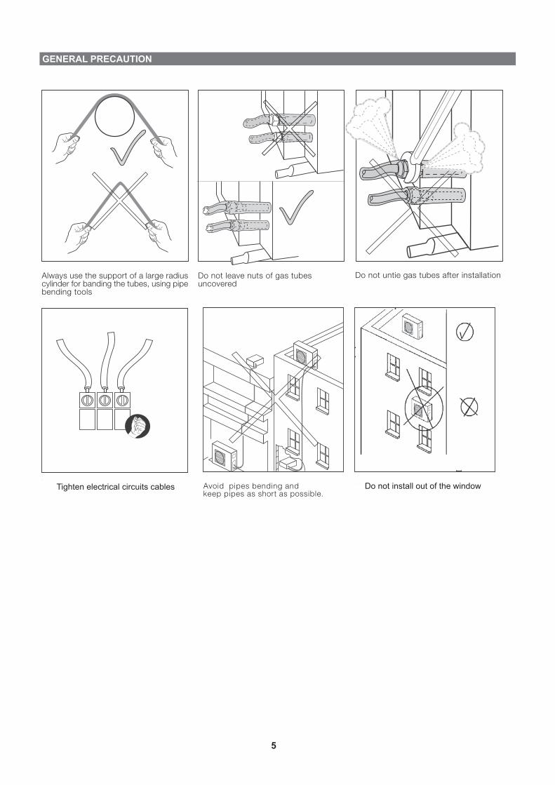
GENERAL PRECAUTION
Always use the support of a large radiuscylinder for banding the tubes, using pipebending tools
Do not leave nuts of gas tubesuncovered
Do not untie gas tubes after installation
Making of a water trap (Siphon)will prevent bad odors and assureproper drainage.
Avoid pipes bending andkeep pipes as short as possible.
Tighten electrical circuits cables Do not install out of the windowTighten electrical circuits cables

6
OUTDOOR UNIT
UNIT DIMENSIONS CLEARANCE AROUND THE UNIT
SEVERAL OUTDOORS INSTALLATION
When installing several outdoors units please take into account the air flow around the units and follow the minimum distance suggestions as shown in the diagrams below.
Row Installation
Air intake side
5 cm or
more25 cm
or more
20 cm or
more
1 m or
more
Back to Back Front to Front
Front to Back
0.5 m or
more
Air intake side
5 m or more
5 m or more
Air intake side
DISPOSAL OF OUTDOOR UNIT DRAIN WATER
In case of using a drain elbow, the unit should be placed on a stand at least 3 cm high.Install the hose with a downward to allow smooth flow of draining water.Use 16mm I.D. tube for drainage.
5 CM
5 CM
100 CM
100 CM
70598380
340350
357
950
970
900

7
PIPING LENGHT
L2
L3
L4 H4
H3
H2
H
L5 H5
L5
L1
H1
L1, L2, L3, L4, L5 � 25 mL1+L2+L3+L4+L5 � 80 mH1, H2, H3, H4, H5, H � 25 m

PIPES CONNECTION
AND FLARRING THE PIPES
PIPE INSULATION
PIPES CONNECTIONS TO THE UNIT
EVACUATION OF PIPES AND INDOOR UNIT
Please use the pipe cutter for cutting the pipes.1.
Remove all burrs by using reamer. Gas leakage might 2.happen If burrs are not removed! Turn pipes edge down to avoid metal powder from entering down the pipes.
After inserting the flare nut into the cooper pipes, 3.please make a flare.
0.0-0.5mmBar
Coppet pipe
Coppet pipe
Reamer
To cut
Inclined
Surfacedamaged
Cracked
Uneventhickness
Please carry out insulation at pipe connection portion 1.as mentioned in Indoor/ Outdoor Unit Installation Diagram. Please wrap the insulated piping end to prevent water from going inside the piping.
If drain hose or connecting pipes is in the room (where 2.dew may form). Please increase the insulation by using POLY-E FOAM with thickness of 9 mm or more.
Vinyl tape
Connecting to the indoor unitAlign the center of the pipes and finger tight the flare 1.nut.Use the torque wranch to tighten the nut firmely.2.
Connecting to the outdoor unitAlign the center of the pipes to the valves.1.Use the torque wranch to tighten the valves firmely 2.according to table:
Flare NutsValve CapService Port Cap
1/413-1813-2011-13
TUBE (Inch)
Torque(N.m) 3/840-4513-2011-13
1/260-6518-2511-13
5/870-7518-2511-13
3/480-8540-5011-13
After connection the unions of the indoor and outdoor units, evacuate the air from the tubes and from the indoor unit is follow:
Connect the charging hoses with a push pin to the low and high 1.sides of the charging set and the service port of the suction and liquid valves. Be sure to connect the end of the charging hose with the push pin to the service port.Connect the center hose of the charging set to a vacuum pump.2.Turn on the power switch of the vacuum pump and make sure 3.that the needle in the gauge moves from 0MPa (0cm Hg) to - 0.1 MPa (-76cm Hg). Let the pump run for fifteen minutes.Close the valves of both the low and high sides of the charging 4.set and turn off the vacuum pump. Note that the needle in the gauge should not move after approximattely five minutes.Disconnect the charging hose from the vacuum pump and from 5.the service ports of the suction and liquid valves.Tighten the service port caps from both valves, and open them 6.using a hexagonal Allen wrench.Remove the valve caps from both valves, and open them using 7.a hexagonal Allen wrench.Remount valve caps onto both of the valves.8.Check for gas leaks from the four unions and from the valve caps. 9.Test with electronic leak detector or with a sponge immersed in soapy water for bubbles.
1. Charging set2. Vacuum pump3. OUTDOOR UNIT4. Service valve5. Cap6. Suction valve7. Service valve*8. Cap9. Liquid valve10. INDOOR UNIT11. Suction flare connection12. Liquid flare connection
1
2
3
45
6
7 8
9
10
11 12
NOTE: For additional charge of various tubinglengths, refer to outdoor unit table.
Sample
8
CUTTING

9
PIPES CONNECTION
Liquid Flare nut – ¼” �Suction Flare nut – 3/8” � (9.53�mm)
UNIT A
Liquid Flare nut – ¼” �Suction Flare nut – 3/8” � (9.53�mm)
UNIT B
Liquid Flare nut – ¼” �Suction Flare nut – 3/8” � (9.53�mm)
UNIT C
Liquid Flare nut – ¼” �Suction Flare nut – 1/2” � (12.7�mm)
UNIT D
Liquid Flare nut – ¼” �Suction Flare nut – 1/2” � (12.7�mm)
UNIT E
For large indoor units of 5.0(18); 6.0(21); 7.0(24) kW – Always use the lower connection points “Unit D” and “Unit E”.

ELECTRICAL CONNECTIONS
1. Electrical wiring and connections should be made by qualified electricians in accordance with local
electrical codes and regulation. The air conditioner units must be grounded.
2. The air conditioner units must be connected to an adequate power outlet from a separate branch circuit
protected by a time delay circuit breaker, as specified on unit's nameplate.
3. Voltage should not vary beyond ± 10% of the rated voltage.
4. For all power supply connections to the outdoor unit, also for the connecting cable between indoor and
outdoor unit, only H05RN-F (60245 IEC 57) cable is to be used. For the optional power supply on the
indoor unit at least H05W-F (60227 IEC 53) is to be used.
5. Prepare the multiple wire cable ends for connection.
6. Take away the Indoor/outdoor cover and open the terminals, take away the cable clamp screw and turn
over the cable clamp.
7. Connect the cable ends to the terminals of the indoor and outdoor units.
8. Connect the other end of the twin wire cable to the outdoor unit twin wire terminal.
9. Secure the multiple wire power cable with the cable clamps.
POWER SUPPLY TO OUTDOOR UNIT POWER SUPPLY TO INDOOR UNIT
SUPPLY NOMINAL CAPACITY
CIRCUIT BRAKER
POWERSUPPLYCABLE
ELECTRICAL CONNECTION SCHEME
LN C LN C LN C LN C
CL N N1L1
(Caseette)
Indoor unit type:CK/CN
Indoor unit B
NC L4
N5 L3
ducted)
Indoor unit type:DLF/LSN
(Low silhouette
Indoor unit C
L CN 5
multi flow)
Indoor unit type:XLF/TOP
(Wall mounted
Indoor unit D
5CN3 L4N 6L
(Ducted)
Indoor unit type:DLS, DNG
Indoor unit E
6 5 N LC4
L
(Wall mounted)
Indoor unit type:LEX, DELTA
Indoor unit A
3x4.0230/1/50
LN
CNL
4x1.5
CNL
4x1.5
CNL
4x1.5
CNL
4x1.5
CNL
4x1.5
LN C
To unit A To unit B To unit C To unit D
1
2
To unit E unit
OUTDOOR UNIT
N
Power supplyto outdoor
L
Main power breaker.1.Power breaker (*by installer).2.
10
POWER SUPPLY O INDOOR UNITS IS NOT ALLOVED!

11
FEATURES SETUP Display Board general description
The display board serves as interface between the installer/technician and the A/C unit. Buttons description: Up & Down - used to scroll between options (up and down) Select - used to select an option Escape - Will go up one level in the menu
THERMAL MODE SETTING
If an indoor unit is defined as the priority unit, the operational mode (Cool/Heat) will be than defined according to this unit. If no unit is selected the default is the first unit to be turned ON defines the mode of operation.
a. No unit priority – Display shows “IdU” (Default value).
b. Unit A is in priority – Display shows “A-p”
c. Unit B is in priority – Display shows “b-p”
d. Unit C is in priority – Display shows “c-p”
e. Unit D is in priority – Display shows “d-p”
f. Unit E is in priority – Display shows “E-p”
g. Forced mode is impied - Display shows “FrC”
Scroll down the "Down" button until setup is displayed
(StP) and than press the "Select" button.
. Scroll down the "Down" button to choose the option
required and press the "Select" button.
Mode (CL/Ht/Sb)
Technician Test (tt)���������������� Technician Test Cool (ttC)
��� Technician Test Heat (ttH)Installation Test (It)
���������������� Number of IDUs (nid)��� Begin test (bgn)��� Test Result (PF)��� Matrix Table Test Result (tbL)��� Problem Correction (Crt)
Diagnostics (diA)���������������� Outdoor Unit (o)
��� Indoor Unit A (a)��� Indoor Unit B (b)
��� Indoor Unit C (c)��� Indoor Unit D (d)��� Indoor Unit E (E)
Set Up (StP)��������������� First IDU Wins (idu)
��� IDU A is master (A-p)��� IDU B is master (b-p)��� IDU C is master (c-p)��� IDU D is master (d-p)��� IDU E is master (E-p)��� ‘Forced mode’ input (Frc)
Up
Down
Esc Select

12
Feature set up with dry contacts (Input)
The input dry contacts are used for controlling an external circuitry which may include a switch or a relay should be used for closing the internal circuit to indicate that some change is required. A wire of up to 1.5mm2 is recommended to be used. Note: NO external power should be used in this case! Night Mode quiet operation
When “Night” dry contact is shorted, the unit will enter to a special mode and reduce the compressor and outdoor fans speed to allow quiet operation.
Stand-By
When “SB” dry contact is shorted, the unit will stop and go to stand by mode.
Power Shedding
When “PWS” dry contact is shorted, the unit will limits its maximum power consumption according to a pre defined value. This value can be changed via the display board (see above procedure).
Feature set up with dry contacts (Output)
Alarm
The alarm dry contacts is used to indicate a problem or any malefunction of the system. An internal relay is used to close an external circuit which may include an external power supply. The external circuit should include some kind of a load (lightening bulb, LED, etc).
Open – Normal Operation Shorted – Quiet operation
Open – Normal Operation Shorted – Stand by
Open – Normal Operation Shorted – Power Shedding
13
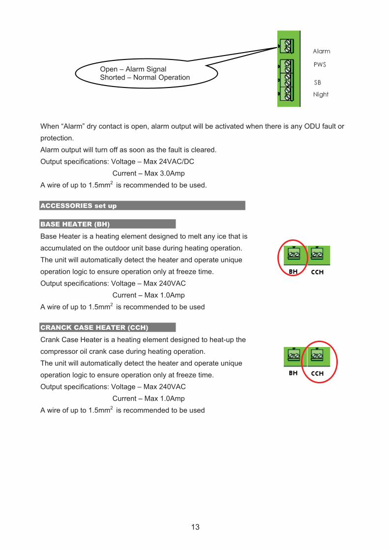
When “Alarm” dry contact is open, alarm output will be activated when there is any ODU fault or protection. Alarm output will turn off as soon as the fault is cleared. Output specifications: Voltage – Max 24VAC/DC Current – Max 3.0Amp A wire of up to 1.5mm2 is recommended to be used. ACCESSORIES set up
BASE HEATER (BH)
Base Heater is a heating element designed to melt any ice that is accumulated on the outdoor unit base during heating operation. The unit will automatically detect the heater and operate unique operation logic to ensure operation only at freeze time. Output specifications: Voltage – Max 240VAC Current – Max 1.0Amp A wire of up to 1.5mm2 is recommended to be used
CRANCK CASE HEATER (CCH)
Crank Case Heater is a heating element designed to heat-up the compressor oil crank case during heating operation. The unit will automatically detect the heater and operate unique operation logic to ensure operation only at freeze time. Output specifications: Voltage – Max 240VAC Current – Max 1.0Amp A wire of up to 1.5mm2 is recommended to be used
Open – Alarm Signal Shorted – Normal Operation

14
INSTALLATION TEST
For proper system operation, each communication cable has to be connected to the corresponding indoor
unit, following the refrigerant tubes. This means that the communication lines Ca. Cb, Cc, Cd and Ce has to
be connected to the indoor units A, B, C, D and E respectively.
To serve this purpose the system is designed to have “installation Test Mode”. When this mode is set, the
unit verifies whether the correct connections were made or not.
Notes:
1. The miswiring check cannot be performed while outdoor temperature is below 5�C. in this case the
display will show “OAT”.
2. The miswiring check cannot be performed if some components in the unit are out of operation. In
this case the display will show the error code “xxx”.
3. The indoor units are turned automatically to installation test mode, no need to turn them ON.
Please follow the steps below:
1. Make sure all wiring and piping to indoor units are
properly connected.
2. Turn ON the power breaker.
3. Enter the number of connected indoor units. (1, 2…5).
Installation Test (It) ������������Number of IDUs (nId)
����������� 1��� 2��� 3��� 4��� 5
4. Enter installation test (It)
a. Entering at first time
Is installation test done before?
Electrical Power Up
Blink “it”
Enter or ESC is pressed? Present Normal HMI Start Installation
test
No
ESCEnter
Yes

15
b. Entering by scrolling the menu (any time)
Enter the test by scrolling down to installation test (It)
1. Press the “Down” button until “It” is shown on
the display.
2. Press “Select”.
3. Scroll down until the display shows “bgn”.
4. Press “Select”.
Mode (CL/Ht/Sb)
Technician Test (tt)
���������������� Technician Test Cool (ttC) ��� Technician Test Heat (ttH)
Installation Test (It) ���������������� Number of IDUs (nid)
��� Begin test (bgn) ��� Test Result (PF) ��� Matrix Table Test Result (tbL) ��� Problem Correction (Crt)
Diagnostics (diA) ���������������� Outdoor Unit (o)
��� Indoor Unit A (a)
��� Indoor Unit B (b) ��� Indoor Unit C (c)
��� Indoor Unit D (d) ��� Indoor Unit E (E)
Set Up (StP) ��������������� First IDU Wins (idu)
��� IDU A is master (A-p)
��� IDU B is master (b-p)
��� IDU C is master (c-p) ��� IDU D is master (d-p) ��� IDU E is master (E-p) ��� ‘Forced mode’ input (Frc)
5. During installation test the system works without the installer interference. It can be observed that the
compressor, outdoor fan, indoor fans are stopped and starts according to preset procedure.
6. The system exits installation test either by continuous press on the escape button for 5 seconds or
when the system finishes installation test by itself after 15 to 19 minutes. During the installation test the
system will count down the remaining time in minutes.
7. After installation test the system stops for 5 minutes and than resumes its normal operation. The
Installation test passed with sucess Installation test failed
8. Upon the judgment code, if required, the installer should correct the communication wiring.
Up
Down
Esc Select
1. Scroll Down
2. Select
Up
Down
Esc Select 3. Scroll Down
4. Select
judgment code is shown on the display – either ‘pass’ or ‘fail’.

16
CHECK LIST BEFORE OPERATION
CHECK THE DRAINAGE EVALUATION OF THE PERFORMANCE
Pour water into the drain tray-styrofoam.
Ensure that water flows out from drain hose of the indoor unit.
Operate the unit at cooling mode and high fan speed for fifteen
minutes or more
Measure the temperature of the intake and discharge air. Ensure
the difference between the intake temperature
and the discharge is more than 8°C.
CHECK ITEMS � Is there any gas leakage at flare nut connections?
� Has the heat insulation been carried out at flare nut connection?
� Is the connecting cable being fixed to terminal board firmly?
� Is the connecting cable being clamped firmly?
� Is the drainage OK?
(Refer to "Check the drainage" section)
� Is the earth wire connection properly done?
�
� Is the power supply voltage complied with rated value?
� Is there any abnormal sound?
� Is the cooling operation normal?
� Is the thermostat operation normal?
� Is the remote control's LCD operation normal?
Is the indoor unit properly mounted to the wall/ceiling?