Framo Connection Philosophy - Eberl Iron Works, Inc. USA Assembly Guideline... · Framo footplate...
31
-
Upload
truongquynh -
Category
Documents
-
view
220 -
download
1
Transcript of Framo Connection Philosophy - Eberl Iron Works, Inc. USA Assembly Guideline... · Framo footplate...


ContentsFramo Connection Philosophy.......................................................................................... - Plate to face / internal connection......................................................................... - Screws and positioning........................................................................................... - Adjustability / connection type............................................................................... - Connection types.................................................................................................... - Connection to primary steel................................................................................... - Adapter plates........................................................................................................ - Welding adapters....................................................................................................Economy of structures......................................................................................................Pipe shoes......................................................................................................................... - Main variants.......................................................................................................... - Anatomy of a pipe shoe.......................................................................................... - Pipe shoe details..................................................................................................... - Framo interfaces..................................................................................................... - I-beam interfaces.................................................................................................... - Double baseplate shoe...........................................................................................U bolts / U clamps.............................................................................................................System assembly details................................................................................................... - Standard connections............................................................................................. - Standard connections.............................................................................................System selection................................................................................................................ - Beam properties..................................................................................................... - Simply supported beam......................................................................................... - L-construction........................................................................................................ - T-construction........................................................................................................ - Cantilever construction.......................................................................................... - H-construction....................................................................................................... - Beam bracket connections.....................................................................................
11234567899
1011
12,1314,15
161718
18,19,20,21,22,23,24
2525252627272829

Plate to Face connection
Internal Connection
1

Self Forming Screw - FLS
Assembly using Self Forming Screws FLS can be made using a hand-held impact driver.Maximum torque applied must not exceed 44 lb-ft
Self Forming Screw - FLS
Screw Positioning
FLS screws used to fasten internal components should be spaced as far apart as possible.The maximum allowable distance between the end face of the Framo section and the component plateshould be 3/8".
2
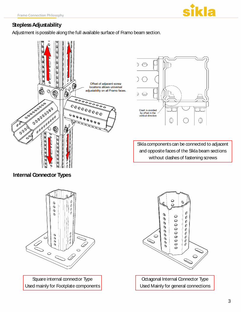
Stepless Adjustability
Sikla components can be connected to adjacentand opposite faces of the Sikla beam sections
without clashes of fastening screws
Internal Connector Types
Square internal connector TypeUsed mainly for Footplate components
Octagonal Internal Connector TypeUsed Mainly for general connections
3
Adjustment is possible along the full available surface of Framo beam section.

Framo face connections can be made over theoctagonal internal connector without clash
Internal Connector Types
The square internal connector will clash withscrews used by Framo face connections
Standard Footplates (WBD) have asquare internal connector
The WBD - T Footplates have anoctagonal internal connector
4
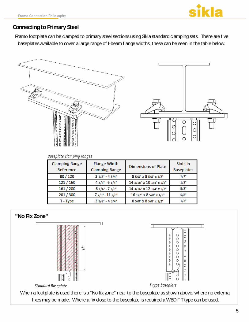
Connecting to Primary SteelFramo footplate can be clamped to primary steel sections using Sikla standard clamping sets. There are five
baseplates available to cover a large range of I-beam flange widths, these can be seen in the table below.
Baseplate clamping ranges
"No Fix Zone"
When a footplate is used there is a "No fix zone" near to the baseplate as shown above, where no externalfixes may be made. Where a fix close to the baseplate is required a WBD F T type can be used.
Standard Baseplate T type baseplate
115

Where a WBD T type or welded cantilever TKO is used, beam connections can be made using aJoining Plate AP.
Joining Plate AP
6

Welding Adapters
Welding adapter component has aweldable corrosion resistant coat-ing, that conforms with health andsafety requirements.
Once the weld is complete, all sur-
faces that exposed to debris from
the weld must be checked for
damage and re-coated if necessary
"No Fix Zone"
Like the range of footplates, there is two types of internal connection available, the square adapter hasthe same "no fix zone". The octagonal type can be used to extend the fix zone up to the beam, how-ever there is some reduction in load capacity as a results
4kt (square adapter) 8kt (octagonal adapter)
7
recommended 1/4"
perimeter fillet weld.
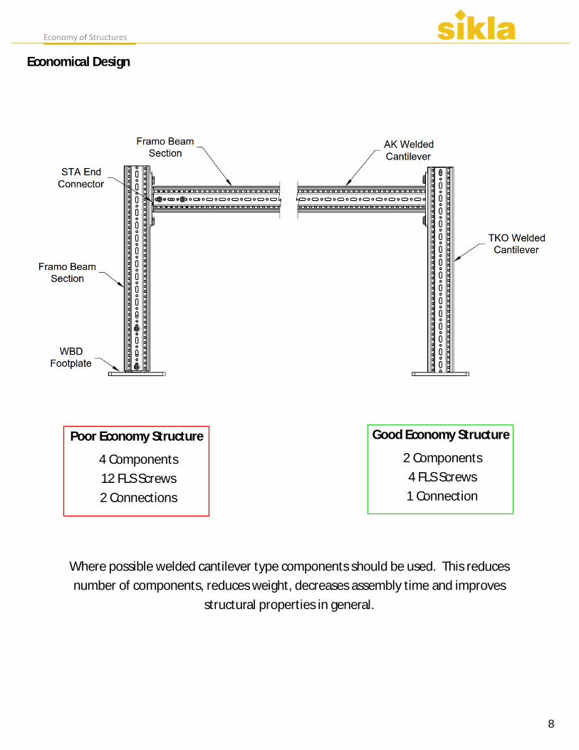
Economical Design
Poor Economy Structure
4 Components 12 FLS Screws 2 Connections
Good Economy Structure
2 Components 4 FLS Screws 1 Connection
Where possible welded cantilever type components should be used. This reducesnumber of components, reduces weight, decreases assembly time and improves
structural properties in general.
8

Main Variants
LA-HV - Single clamp, Single baseplate - Clamping range 1/2" - 6" - Height adjustable - For pipe diameters 1/2" - 6"
LC-HV - Double clamp, Single baseplate - Clamping range 1/2" - 12" - Height adjustable - For pipe diameters 1/2" - 12"
LD-HV - Double clamp, Double baseplate - Clamping range 8" - 24" - Height adjustable - For pipe diameters 8" - 24"
9

Anatomy of a pipe shoe
10

The three main variants (LA,LC,LD)have three height options HV90,
HV150 and HV200.
Pipe shoe details
Bolts for height adjustability.Tightening torque 59 lb-ft
11

Pipe shoe Framo Interfaces
Sliding Support
Guiding Support
- Pipe shoe can be rested on Framosecondary steelwork beam. Recom-mended minimum bearing surface ofsupporting steelwork is 3 1/8"
- Allowable forces for pipe shoe andinterface published at the end of thisguide. These should be used in com-bination with the allowable loads forthe supporting Framo system.
- A guided support can be achieved us-ing the "Guiding Bracket FW F" thatmatches the Framo section size
- Allowable forces for pipe shoe andinterface published at the end of thisguide. These should be used in com-bination with the allowable loads forthe supporting Framo system.
12

Pipe shoe Framo Interfaces
- A Fixed Point or "Line Stop" supportcan be achieved using the "Fixed PointBracket XW F" that matches the Framobeam section size.
- The Nylon slide plate is removedfrom the pipe shoe revealing the fixedpoint notches in the shoe base plate.
- The plate on the "Fixed Point BracketXW F" locks into the shoe platenotches to create the fixed point.
- Allowable forces for pipe shoe andinterface published at the end of thisguide. These should be used in com-bination with the allowable loads forthe supporting Framo system.
Fixed Point Support
Fixed Point Support - (Plan View)
13

Pipe shoe I-Beam Interfaces
Sliding Support
Guiding Support
Pipe shoe I-Beam Interfaces
- Pipe shoe can be rested on a second-ary steelwork beam.
- Recommended minimum bearingsurface of 3 1/8"
- Allowable forces for pipe shoe andinterface published at the end of thisguide.
- A guiding support can be achievedusing the "Guiding Set FS F" thatmatches the steel beam flange width.
- Allowable forces for pipe shoe andinterface published at the end of thisguide.
14

- A Fixed Point or "Line Stop" supportcan be achieved using the "Guiding SetFS F" that matches the steel beamflange width.
- The Slide plate on the pipe shoe isremoved revealing the fixed pointnotches in the shoe base plate.
- The plate on the "Fixed Point Set XFS" locks into the revealed notches tocreate the fixed point.
- Allowable forces for pipe shoe andinterface published at the end of thisguide.
Fixed Point Support
Fixed Point Support - (Plan View)
Pipe shoe I-Beam Interfaces
15

Pipe shoe interfaces
LD-HV (Double Baseplate)
LD-HV type shoes (Double Baseplate) require 2 connections per single pipe shoe unit, whenrequired either as a guided support or fixed point support
16

U-Bolt Framo Interfaces
1/2" - 1 1/2" Pipes
2" - 3" Pipes
4" - 6" / 8" - 12" / 14" - 20" Pipes
- U-bolts 1/2" - 1 1/2" can be attached toFramo beam section using the single bracket(UBF 1/2" - 1 1/2") using 2 FLS screws.
- A Nylon slidepad can be clipped on to theFramo surface to act an insulator and toprovide surface protection if required (Pad U-UB F)
- U-bolts 2" - 3" can be attached to Framoprofiles using the single bracket (UBF 2" - 1 3")using 2 FLS screws.
- A Nylon slide pad can be clipped on to theFramo surface to act an insulator and toprovide surface protection if required (Pad U-UB F)
- U-bolts 4" - 6", 8" - 12" or 14" - 20" can beattached to Framo profiles using two brackets(UBF 4" - 6", UBF 8" - 12" or UBF 14" - 20") us-ing 2 FLS screws.
- A Nylon slide pad can be clipped on to theFramo surface to act an insulator and toprovide surface protection if required (Pad U-UB F)
17

Standard ConnectionsSTA F80 / F100
STA F80 / F100 E
1018

STA F100 - 100/160
STA F100 - 100/160 E
19

STA F80-30
WD 140/140
20

Pivot Joint GE
Pivot Joint GE F (with baseplate)
21

Beam Section Holder TPH-C
U Holder SB
22

Bracing Arm SKO F100
Beam Section Holder TPH
23

WBD F80 / F100
WBD F100/160
24

Working Loads for the Framo systemBeam Properties
Simply Supported Beam
Fz as a dead load at L/2Max. Deflection L/200
25

L-Construction
F80 Construction;1x End Support WBD F80 121/1601x Beam Section TP F 801x Cantilever Arm AK F808 Self forming screws FLS
F100 Construction;1x End Support WBD F100 121/1601x Beam Section TP F 1001x Cantilever Arm AK F1008 Self forming screws FLS
F100/160 (1) Construction:1x End Support WBD F100/160 121/1601x Beam Section TP F 100/1601x Cantilever Arm AK F10012 Self forming screws FLS
F100/160 (2) Construction:1x End Support WBD F100/160 121/1602x Beam Section TP F 100/1602x Corner bracket WD 140/14024 Self forming screws FLS
Fz as a dead load at distance L; Fx as a variable load distance L.Friction coefficient µ0 = 0.2 in longitudinal direction.Max deflection H/100; L/100End Support WBD may be exchanged with welding adapters to achieve the same load rating.
26

Framo F80 Construction:1x End Support WBD F80-121/1602x Beam Section TP F 802x End Connector STA F 8012x Self Forming Screw FLS
Framo F100 Construction:1x End Support WBD F100-121/1602x Beam Section TP F 1002x End Connector STA F 10012x Self Forming Screw FLS
Framo F160/100 Construction:1x End Support WBD 100/160-121/1602x Beam Section TP F 100/1602x Corner Bracket WD F 10024x Self Forming Screw FLS
Fz as a dead load; Fx as a variable load.Values allow for a Load placement ±2” from the centre of thestructure.Assumed friction coefficient µ0 = 0.2 in longitudinal direction.Max deflection H/150End Support WBD may be exchanged with welding adapters toachieve the same load rating.
T-Construction
Cantilever Construction
Variant 1 Framo F100Clamped to Primary Structure1 x Cantilever TKO F1001 x Assembly Set P21 x Joining Plate 121/160
Variant 2 Framo F100Clamped to Primary Structure1 x Cantilever TKO F100Anchor bolts to concrete structure.
Variant 1 Framo F100/160Clamped to Primary Structure1 x Cantilever TKO F1001 x Assembly Set P2
Variant 2 Framo F100/160Clamped to Primary Structure1 x Cantilever TKO F100/160Anchor colts to concrete structure
27
End Support WBD may be exchanged with welding adapters to achieve the same load rating.

H - Construction
Framo F80 Construction:2x End Support WBD F80-121/1603x Beam Section TP F 802x End Connector STA F 8024x Self Forming Screw FLS
Framo F100 Construction:2x End Support WBD F100-121/1603x Beam Section TP F 1002x End Connector STA F 10024x Self Forming Screw FLS
Framo F100/160 Type A Construction:2x End Support WBD F100/160-121/1602x Beam Section TP F 100/1601x Beam Section TP F 1002x End Connector STA F 10024x Self Forming Screw FLS
Framo F100/160 Type B Construction:2x End Support WBD F100/160-121/1603x Beam Section TP F 100/1604x WD F100 Corner Bracket48x Self Forming Screw FLS
Fz as a dead load at position L/2; Fx as a variable load in the same position.Assumed friction coefficient µ0 = 0.2 in longitudinal direction.Max deflection L/200.
28

Beam Bracket Connections
Beam Bracket F100 Vertical Installation
1 x Beam Section TP F1002 x U-Holder SB F 100-40
Beam Bracket F100 Horizontal Installation
Beam Bracket F100/160 Horizontal Installation
1 x Beam Section TP F100/1602 x U-Holder SB F 100/160-40
Beam Bracket F100/160 Vertical Installation
Fz as a dead load at position L/2; Fx as a variable load in the same position.Assumed friction coefficient µ0 = 0.2 in longitudinal direction.Max deflection L/100
Fz as a dead load at position L/2; Fx as a variable load in the same position.Assumed friction coefficient µ0 = 0.2 in longitudinal direction.Max deflection L/100
29