frame buckling resistance and structural...
47
2/18/2010 1 Buckling Resistance of Frames Buckling Resistance of Frames and and Requirements for elastic and Requirements for elastic and Buckling Resistance of Frames Buckling Resistance of Frames and and Requirements for elastic and Requirements for elastic and advanced structural analysis advanced structural analysis advanced structural analysis advanced structural analysis Prof Dr Prof Dr Shahrin Shahrin Mohammad Mohammad Assoc Prof Dr Ahmad Assoc Prof Dr Ahmad Baharudin Baharudin Abdul Abdul Rahman Rahman 24 24 th th Feb 2010 Feb 2010 Eurocode 3 DESIGN CHECKS MEMBER BEHAVIOUR : bucking CHECKS CROSS- SECTIONAL BEHAVIOUR FRAME BEHAVIOUR : buckling resistance of frames bucking resistance of beams and columns Dr Hafizah Dr Sooi Dr Bahar/Shahrin
Transcript of frame buckling resistance and structural...

2/18/2010
1
Buckling Resistance of Frames Buckling Resistance of Frames and and
Requirements for elastic and Requirements for elastic and
Buckling Resistance of Frames Buckling Resistance of Frames and and
Requirements for elastic and Requirements for elastic and advanced structural analysisadvanced structural analysisadvanced structural analysisadvanced structural analysis
Prof Dr Prof Dr ShahrinShahrin MohammadMohammadAssoc Prof Dr Ahmad Assoc Prof Dr Ahmad BaharudinBaharudin Abdul Abdul RahmanRahman
2424thth Feb 2010Feb 2010
Eurocode 3
DESIGN CHECKS
MEMBER BEHAVIOUR :
bucking
CHECKS
CROSS-SECTIONAL BEHAVIOUR
FRAME BEHAVIOUR :
buckling resistance of
frames
bucking resistance of
beams and columns
Dr Hafizah
Dr Sooi
Dr Bahar/Shahrin

2/18/2010
2
Eurocode 3
Dr HafizahTENSIONcl.6.2.3
CROSS-SECTION
RESISTANCE
COMPRESSIONcl. 6.2.4
BENDINGcl.6.2.5
BENDING SHEAR &
DESIGN CHECKS
BUCKLING RESISTANCE
SHEARcl.6.2.6
TORSIONcl.6.2.7
BENDING & SHEARcl.6.2.8
BENDING & AXIAL LOADcl.6.2.6
BENDING, SHEAR & AXIAL LOAD
cl.6.2.6
Eurocode 3
DESIGN CHECKSDr Sooi
BUCKLING RESISTANCE
Bending and axial compression
cl.6.3.3
Bending
CHECKS
CROSS-SECTION
RESISTANCE
gcl.6.3.2
Compressioncl.6.3.4

2/18/2010
3
(1) Depending on the character of the individual clauses, distinction is made in EN 1990 between Principles and Application Rules.
Distinction between Principles and Application Rules
between Principles and Application Rules.(2) The Principles comprise :
• general statements and definitions for which there is no alternative• requirements and analytical models for which no alternative is permitted unless
specifically stated.(3) The Principles are identified by the letter P following the paragraph number.(4) The Application Rules are generally recognised rules which comply with the Principles
and satisfy their requirements.and satisfy their requirements.(5) It is permissible to use alternative design rules different from the Application Rules
given in EN 1990 for works, provided that it is shown that the alternative rules accord with the relevant Principles and are at least equivalent with regard to the structural safety, serviceability and durability which would be expected when using the Eurocodes.

2/18/2010
4
Section 5 Structural analysis and design assisted by testing• Structural analysis
• Modeling appropriate to limit states • Established engineering theory and to be verified if necessary
• Static actions, dynamic actions, fire design• Design assisted by testing

2/18/2010
5
Introduction to Eurocode 3
• the principles of design, concept and formulation are generally similar to BS5950BS5950
• the main differences of the two design rules are only in the symbols, terms, safety factors and limits adopted
• distinction is made between– principles which must be obeyed– application rules which follow the principles but alternative methods are
9
pp p pallowed
• design capacities in EC3 are categorised under cross-section resistance and member buckling resistance (based on structural behaviour and not based on element/member)
Introduction to Eurocode 3
• based on limit state design principles which require that specific 'failure' g p p q pconditions must be checked for both ultimate and serviceability conditions
• variability, principally of actions and materials, is accounted for by partial safety factors which also incorporate a global margin of safety
• EC3 incorporates theories in the first-order and second order which consider the effects of deformations
10
• EC3 allows us to choose the degree of accuracy of the structural analysis
• allows for the “advanced analysis approach” in analysis and design as an alternative to simplified design method

2/18/2010
6
Introduction to Eurocode 3
• frame imperfection(P D and P d effect ) to be included in the • frame imperfection(P-D and P-d effect ) to be included in the structural modeling of frames
• a comprehensive information on the elastic-perfectly plastic and elasto-plastic methods for continuous and semi-continuous steel framing
• providing classification of the connections based on strength and rigidity
11
and rigidity • the information on frame stability is presented in detailed
whilst the terms sway and non-sway frames are well defined
ff Eurocode 3 : Content
Whole of Chapter 5 is dedicated to Structural Analysis and Frame Behaviour

2/18/2010
7
Eurocode 3 : Content
• Design checks are required and it depends on the type of • Design checks are required and it depends on the type of Design checks are required and it depends on the type of structure
• Frames are checked for • Static equilibrium• Frame stability• Resistance of cross-sections
Design checks are required and it depends on the type of structure
• Frames are checked for • Static equilibrium• Frame stability• Resistance of cross-sections
14
• Resistance of members• Resistance of joints
• Tension members need only checked for resistance of cross-sections
• Resistance of members• Resistance of joints
• Tension members need only checked for resistance of cross-sections

2/18/2010
8
EurocodeEurocode 3 :3 :EurocodeEurocode 3 :3 :EurocodeEurocode 3 : 3 : Design of Steel StructuresDesign of Steel Structures
EurocodeEurocode 3 : 3 : Design of Steel StructuresDesign of Steel Structures
Frame Frame IdealisationIdealisation, Classification and Analysis, Classification and Analysis
General approach in analysing and designing steel frames
• Classification of the frames• Assessment of imperfections• Choice of the method of analysis• Computation of internal member and moments• Ultimate limit states check
resistance of cross sections
16
– resistance of cross-sections– Buckling resistance of members
• Serviceability limit states check– Deflections– Dynamic effects

2/18/2010
9
Braced and unbraced ?
Sway and non-sway?Semi-rigid
and rigid?
drown with terminologies?drown with terminologies?
and rigid?Elastic vs inelastic?
Elastic and plastic ?
Linear and non-linear?
Continuous vsContinuous vs semi-continuous?
Elastic vs elasto plastic? Joints vs
connectionsAdvanced analysis?
Rigid, elastic-plastic, elastic plastic hinged?
FrameFrame IdealisationIdealisation andandFrameFrame IdealisationIdealisation andandFrame Frame IdealisationIdealisation and and ClassificationClassification
Frame Frame IdealisationIdealisation and and ClassificationClassification

2/18/2010
10
FF Id li tiId li tiFF Id li tiId li tiFrame Frame IdealisationIdealisationFrame Frame IdealisationIdealisation
Sway Stability
Consideration whether a frame is sway or non-sway case:• Depends on frame geometry and load cases under consideration• Determined by influenced of PΔ effect
Non-sway frame • Horizontal loads are carried by the bracing or by horizontal support• Change of geometry (2nd-order effect) is negligible
20
g g y ( ) g g
Sway frame • Horizontal loads are carried by the frame• Change of geometry (2nd-order effect) is significant

2/18/2010
11
Multistorey Steel FrameMultistorey Steel Frame
Sway StabilitySway Stability
Horizontal loads are carried by the bracing or by horizontal support
Horizontal loads are carried by the frame
Non-sway SwayDepends on frame geometry and load cases under consideration
Determined by influenced of PΔ effect
Defin
iton
21
Change of geometry (2nd-order effect) significant
Change of geometry (2nd-order effect) is negligible
nSway Stability
A frame is considered to be sway case if:
analysis plasticfor 15
analysis elasticfor 10
≥=
≥=
Ed
crcr
Ed
crcr
FFFF
α
α
where
22
αcr is the factor by which the design loading would have to be increased to cause elastic instability in a global mode
FEd is the design loading on the structureFcr is the elastic critical buckling load for global instability mode based on initial
elastic stiffnesses

2/18/2010
12
Sway Stability
αcr may be calculated using the following approximate formula,
where:
δH ed is the sway at the top of storey i
⎟⎟⎠
⎞⎜⎜⎝
⎛⎟⎟⎠
⎞⎜⎜⎝
⎛==
Ed
Ed
EdHEd
crcr V
HhFF
,δα
φ φh
δH,ed
H1
H2V V
23
H,ed y p yh is the height of storey iHEd the total horizontal reactions
respectively at the bottom of storey IVEd the total vertical reactions respectively
at the bottom of storey i
1 2HEd = H1 + H2VEd = V1 + V2
Allowing Imperfections
N
Φ Φ
L eo,d
always to be allowed foronly for slender members in sway frames, otherwise it is covered in the relevant buckling curve
Frame imperfection Member Imperfection
2/18/2010
13
Allowing frame imperfectionF1
φF1
φ φ
F2φ F2
φ(F1 F2)/2 φ (F1+F2)/2
• Frame imperfection can be replaced by an equivalent closed system of horizontal forces applied at the floor levels (including the foundation level).
φ(F1+F2)/2 φ (F1+F2)/2
Equivalent forces
Frame imperfection
• The frame imperfection is as follows:
115,0
132but 2
200/1 0
⎟⎠⎞
⎜⎝⎛ +=
≤≤⎟⎠
⎞⎜⎝
⎛=
==
m
h
where
m
hh
mho
α
αα
φααφφ
⎠⎝ m
h is the height of the structure in metersm is is the number of columns in a row including only those columns which
carry a vertical load

2/18/2010
14
Number of columns (m)Height of
the structure
(h)1 2 3 4 5 6
1 0.00500 0.00433 0.00408 0.00395 0.00387 0.00382
2 0.00500 0.00433 0.00408 0.00395 0.00387 0.00382
3 0.00500 0.00433 0.00408 0.00395 0.00387 0.00382
Global initial sway imperfections φ,
132but 2
200/1 0
≤≤⎟⎠
⎞⎜⎝
⎛=
==
h
where
hh
mho
αα
φααφφ
4 0.00500 0.00433 0.00408 0.00395 0.00387 0.00382
5 0.00447 0.00387 0.00365 0.00353 0.00346 0.00341
6 0.00408 0.00354 0.00333 0.00323 0.00316 0.00312
7 0.00378 0.00327 0.00309 0.00299 0.00293 0.00289
8 0.00354 0.00306 0.00289 0.00280 0.00274 0.00270
9 0.00333 0.00289 0.00272 0.00264 0.00258 0.00255
10 0.00333 0.00289 0.00272 0.00264 0.00258 0.00255
12 0.00333 0.00289 0.00272 0.00264 0.00258 0.00255
13 0.00333 0.00289 0.00272 0.00264 0.00258 0.00255
14 0.00333 0.00289 0.00272 0.00264 0.00258 0.00255
115,0
3
⎟⎠⎞
⎜⎝⎛ +=
⎠⎝
m
h
mα
F2
φF2
φF1
F1
14 0.00333 0.00289 0.00272 0.00264 0.00258 0.00255
15 0.00333 0.00289 0.00272 0.00264 0.00258 0.00255
16 0.00333 0.00289 0.00272 0.00264 0.00258 0.00255
17 0.00333 0.00289 0.00272 0.00264 0.00258 0.00255
18 0.00333 0.00289 0.00272 0.00264 0.00258 0.00255
19 0.00333 0.00289 0.00272 0.00264 0.00258 0.00255
20 0.00333 0.00289 0.00272 0.00264 0.00258 0.00255
22 0.00333 0.00289 0.00272 0.00264 0.00258 0.00255
24 0.00333 0.00289 0.00272 0.00264 0.00258 0.00255
25 0.00333 0.00289 0.00272 0.00264 0.00258 0.00255
φ φ
Equivalent forces
Δ2
Δ1φF1
φF2
h1
h2h
F1
F2
h1
h2
21
11 Δ−Δ
=h
Hedδ
32
22 Δ−Δ
=h
Hedδ
Δ4
Δ3φF3
φF4
H1 H2 H3
h3
h4
F3
F4
h3
h4
43
33 Δ−Δ
=h
Hedδ
4
44 Δ
=h
Hedδ
⎟⎟⎠
⎞⎜⎜⎝
⎛ hmaxδ
Elastic Analysis
αcr < 10 Sway Frame
Non-Sway Frame
Plastic Analysis
αcr ≥10
Sway Frame
Non-Sway Frame
αcr < 15
αcr ≥15
⎟⎟⎠
⎞⎜⎜⎝
⎛⎟⎟⎠
⎞⎜⎜⎝
⎛==
Ed
Ed
EdHEd
crcr V
HhFF
,
maxδ
α
⎟⎠
⎜⎝ EdH ,δ

2/18/2010
15
Example: Check if the frame is a sway frame
3 5m
F1φF1
F2
F1
F2 3.5m
3.5m
3.5m
3.5m7m 7m 7m
F2
F3
F4
φF2
φF3
φF4
7m 7m 7m
F2
F3
F4
F1=850 kNF2= F3=F4 = 3750 kN
From slide 13, m=3 and h=14m, thereforeφ = 0.00272

2/18/2010
16
3.5m
850 kN2.31kN
3750 kN10.2 kN
Say absolute deflections from frame analysis7.5 mm
6 mm h ⎟⎞
⎜⎛
Example: Check if the frame is a sway frame
3.5m
3.5m
3.5m
3750 kN
3750 kN10.2 kN
10.2 kN
⎟⎞
⎜⎛⎟⎞
⎜⎛
Edcr HhF
4 mm
2 mm
mmh
EdH
17502/3500max,
==⎟⎟⎠
⎞⎜⎜⎝
⎛
δ
3025 kN 3025 kN 3025 kN 3025 kN
8.228 kN 8.228 kN 8.228 kN 8.228 kN
Elastic Analysisαcr < 10 Sway Frame
αcr ≥10 Non-Sway Frame
⎟⎟⎠
⎜⎜⎝⎟⎟⎠
⎜⎜⎝
==Ed
Ed
EdHEd
crcr VF ,
maxδ
α
where:
δH,ed is the sway at the top of storey ih is the height of storey iHEd the total horizontal reactions
respectively at the bottom of storey IVEd the total vertical reactions respectively
at the bottom of storey i
8.412100
91.321750 =⎟⎠⎞
⎜⎝⎛=crα
Plastic Analysisαcr < 15
αcr ≥15
Sway Frame
Non-Sway Frame
Therefore it is a sway frame
MultistoreyMultistorey Steel FrameSteel Frame
Sway StabilitySway Stability
Horizontal loads are carried by the bracing or by horizontal support
Horizontal loads are carried by the frame
Non-sway SwayDepends on frame geometry and load cases under consideration
Determined by influenced of PΔ effect
Definiton
Change of geometry (2nd-order effect) significant
Change of geometry (2nd-order effect) is negligible
Analysis and design ?

2/18/2010
17
F l ifi tiF l ifi tiF l ifi tiF l ifi tiFrame classificationFrame classificationFrame classificationFrame classification
Joints in frameJoints in frame
The effects of the behaviour of the joints in analysing frame structure, may generally be neglected, however if such effects are significant. they should be g y g , g ytaken into account.
To know whether the joint behaviour is significant or not, joint are classified into:
• Simple- joint may be assumed not to transmit bending moments;
• Continuous the behaviour of the joint may be assumed to have no effect on the analysis;
34
- the behaviour of the joint may be assumed to have no effect on the analysis;• Semi-continuous
- the behaviour of the joint needs to be taken into account in the analysis

2/18/2010
18
Types of constructionTypes of construction
Simple Semi-continuous Continuous
- connections between members are assumed not to develop moments
- joint pin connected
- connections between members capable to develop full strength/stiffness
- joint rigidly connected
- some degree of connection stiffness is assumed
- joint semi-rigidly connected
35
- necessary to maintain stability against sway
- elastic analysis
j g y
- elastic analysis or plastic analysis
- Limitation in the design specifications
- elastic or plastic analysis- elastic-plastic analysis- elasto-plastic analysis

2/18/2010
19
38

2/18/2010
20
39

2/18/2010
21
42

2/18/2010
22
43
Typical Joints Expressed In Term of M-φ Curves
T-Stub
Simple construction Double angle web cleats
Mom
ent,
M
top and seating cleat
end-plate Flexible end platesFin plates
Semi-continuous constructionFlushed end platesExtended end plates
44Rotation, θ
single web angle
double web angle
header plateContinuous Construction
WeldedMini-haunch

2/18/2010
23
Joints in frame Joints in frame –– EC3EC3
Connections can be classified according to:
1) Moment Resistance full strength (continuous design) partial strength (semi-continuous design) nominally pinned (simple construction design).
2) Rotational Stiffness
45
2) Rotational Stiffness rigid, semi-rigid, and nominally pinned
3) Rotation Capacity - ductility
1. Moment Resistance• Full strength - a
connection with moment resistance at least equal to that of the memberto that of the member.
• Partial strength - a connection with moment resistance, which is less than that of the member.
N i ll i d
46
• Nominally pinned - a connection, which is sufficiently flexible with moment resistance not greater than 25% of Mcx.

2/18/2010
24
1. Moment Resistance
• Continuous design is a design of frame where connections are considered as rigid joints for elasticconnections are considered as rigid joints for elastic analysis and full strength joints for plastic analysis.
• Semi-continuous design is a design of frame where semi-rigid connections are modelled as rotational springs and partial strength connections are modelled as plastic hinges.
47
p g
• Simple construction design is a design of frame where the connections are assumed not to develop moments that affect the connected members.
2. Rotational Stiffness • Rigid - a connection which is
stiff enough for the effect of its flexibility on the frame bending moment diagram to be neglected and with minimum deformation and rotation.
• Semi-rigid - a connection, hi h i t fl ibl twhich is too flexible to
quantify as rigid but is not a pin.

2/18/2010
25
3. Rotation Capacity
Ductile connection - a connection, which has a capacity to rotate sufficiently to form a plastic hinge.
49
Type of Multistorey
Relationship between type of frame and constructionyp y
Steel Frame
Non Sway Frame Sway FrameTypes of frame
Simple Semi-continuous
Continuous
Types of construction
ContinuousSemi-continuous

2/18/2010
26
Summary
• The frame has first to be idealised• The frame has first to be idealised
• Then a frame classification is carried out– sway-non sway– type of construction - connections
51
• then the method of analysis is will be selected … (refer next section)
F l ifi tiF l ifi tiF l ifi tiF l ifi tiFrame classificationFrame classificationFrame classificationFrame classification

2/18/2010
27
Global frame analysis
• Aims of global frame analysisg y– Determine the distribution of the internal forces– Determine the corresponding deformations
• Means– Adequate models incorporating assumptions about the
53
Adequate models incorporating assumptions about the behaviour of the structure and its component:members and joints
Requirements for analysis
• Basic principles to be satisfied:Basic principles to be satisfied:– Equilibrium throughout the structure– Compatibility of deformation between the frame components– Constitutive laws for the frame components
54
• Frame model - element model– must satisfy the basic principles

2/18/2010
28
Frame behaviour
• Actual response of the frame is non linear
– Linear behaviour limited
– Non-linear behaviour due to: • Geometrical influence of the actual deformed shape
(second order effects)• Joint behaviour
55
Joint behaviour• Material yielding
Frame behaviour
DisplacementLoadL d t
Full elastic Load parameter
Elastic limit
Peak load
responseλ
Frame
Displacement parameter
Elastic limit

2/18/2010
29
Δ3
Δ2
Δ1φF1
φF2
φF3
h1
h2
21
11 Δ−Δ
=h
Hedδ
32
22 Δ−Δ
=h
Hedδ
33 Δ−Δ
=h
Hedδ
Δ4
φ
φF4
H1 H2 H3
h3
h4
43 Δ−Δ
4
44 Δ
=h
Hedδ
Factors affecting the deformation values;1.Material properties2.Geometry of the structure3.Boundary condition4.Loadings
P ΔP
Loa
d, P
PE
First Order Elastic
S d O d El ti
Elastic Buckling Load(a)
(b)
PP
Second Order Elastic
First Order Rigid-Plastic
First Order Elastic-Plastic (Hinged)
Second Order Rigid-Plastic
(e)
(c)
(d)
(b)
Choice of Choice of analysisanalysis
Displacement δ
Rigid PlasticAccounting P-δ and P-ΔSecond Order
Elastic-Plastic(Hinged)
Second Order Elasto-Plastic(spread of yield)
TRUE BEHAVIOUR
(f)
(g)

2/18/2010
30
Decisions related to the analysis approach – EC3
Choice between – an elastic and a plastic global analysis– 1st order and 2nd order analysis– a traditional approach and a modern
approach to connection representation
59
approach to connection representation– Combination of the above
Implications for design of the choice of the global analysis
Sophistication in the method of analysis
effort required
Global analysis
ULS design checks
60
Overall Design Task= Analysis + Design Checks
Simplification in the method of analysis

2/18/2010
31
Relationship between type of frame, construction and analysisType of Multistorey Steel Frame
Non Sway Frame Sway Frame
stabiy y
Simple Semi-continuous Continuous
Fi t d
ContinuousSemi-continuous
ilityConnection
geo
61
First order analysis 2nd order analysis
Simple or Pin analysis
First order analysis
Elastic global analysis
Plastic global analysis
Elastic global analysis
Plastic global analysis
Elastic-Plastic analysis
Nonlinear Plastic analysis
Rigid Plastic analysis
ometry
material
Sway Stability
A frame is considered to be sway case if:
stabilitygeo
analysis plasticfor 15
analysis elasticfor 10
≥=
≥=
Ed
crcr
Ed
crcr
FFFF
α
α
where
ometry
62
αcr is the factor by which the design loading would have to be increased to cause elastic instability in a global mode
FEd is the design loading on the structureFcr is the elastic critical buckling load for global instability mode based on initial
elastic stiffnesses

2/18/2010
32
1st and 2nd order analysisgeom
etry
1st order analysis - Indefinite linear• elastic response of member sections
• 2ND order analysis– Indefinite linear- elastic
response of member sections and joints
sections• geometry and • connections
1st order analysisLoad parameter
2nd order elastic analysis
λcr
63
and joints
– Equilibrium established for the deformed structure
– Allows for P-D effect and, if necessary, for P-d effect
2nd order elastic analysis
Displacement parameter
Multistorey Steel FrameMultistorey Steel Frame
Non-sway SwayDepends on frame geometry and load cases under consideration
Determined by influenced of PΔ effect
De
geometry
material
MethGeom
Horizontal loads are carried by the bracing or by horizontal support
Horizontal loads are carried by the frame
Change of geometry (2nd-order effect) significant
Change of geometry (2nd-order effect) is negligible
Determined by influenced of PΔ effect
First-order elastic analysis with indirect allowance for second order effect
(P-Δ and P-δ effect)First-order elastic analysis
(stifness analysis, moment distribution)
efinitonhod of analysis
metry and m
aterial
First-order rigid-plastic analysisFirst-order rigid-plastic analysis with
indirect allowance for second order effect(P-Δ and P-δ effect)
Second-order elastic analysis
Second-order elastic plastic hinged analysisSecond-order elasto-plastic analysis

2/18/2010
33
Connection modelling in frame analysis
• Framing and joints
C ti f i i id j i t
Connection
– Continuous framing: rigid joint– Simple framing: pinned joint– Semi-continuous framing: semi-rigid joint
The main approaches are:the traditional approach in which the joints are considered as
65
(nominally) pinned or rigid the semi-rigid approach in which a more realistic model representing the joint behaviour is used. It is usually introduced as a spiral spring at the extremity of the member it attaches (usually the beam).
Steel FrameSteel Frame
Non-sway SwayDepends on frame geometry and load cases under consideration
M
Horizontal loads are carried by the bracing or by horizontal support
Horizontal loads are carried by the frame
Change of geometry (2nd-order effect) significant
Change of geometry (2nd-order effect) is negligible
Determined by influenced of PΔ effect
First-order elastic analysis with indirect allowance for second order effect
(P-Δ and P-δ effect)
First-order elastic analysis(stifness analysis, moment distribution)
Definiton
Elastanaly
66
Method of analysis
(P-Δ and P-δ effect)
First-order rigid-plastic analysisFirst-order rigid-plastic analysis with indirect
allowance for second order effect(P-Δ and P-δ effect)
Second-order elastic analysis
Second-order elastic plastic hinged analysis
Second-order elasto-plastic analysis
tic ysis
Plastic analysis

2/18/2010
34
Summary
• The frame has first to be idealised
• Then a frame classification is carried out⇒ sway-non sway / braced-unbraced
• On the basis of the frame class (and the type of steel and profiles), the type of frame analysis is finally selected
Choice of type analysis/design: depends on type of structure,
67
Choice of type analysis/design: depends on type of structure, available tools , EC3 requirements, etc. The more sophisticated the analysis tool used, the lesser the design ULS checks
Frame DesignFrame DesignFrame DesignFrame Design
2/18/2010
35
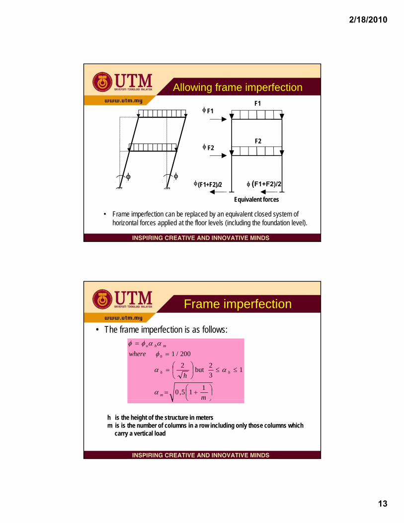
Conception to final design
Environmental considerations
Architecturalrequirements
Execution considerationsConception
Structural solutions:sound and economic Fabricator
Preliminarydesign Analysis Final design
Decisions related to the analysis approach – EC3
• Choice between • Choice between – an elastic and a plastic global analysis– 1st order and 2nd order analysis– a traditional approach and a modern approach to
connection representation
70
– Combination of the above

2/18/2010
36
Implications for design of the choice of the global analysis
Sophistication in the method of analysis
effort required
Global analysis
ULS design checks
71
Overall Design Task= Analysis + Design Checks
Simplification in the method of analysis
Steel FrameSteel Frame
Non-sway SwayDepends on frame geometry and load cases under consideration
M
Horizontal loads are carried by the bracing or by horizontal support
Horizontal loads are carried by the frame
Change of geometry (2nd-order effect) significant
Change of geometry (2nd-order effect) is negligible
Determined by influenced of PΔ effect
First-order elastic analysis with indirect allowance for second order effect
(P-Δ and P-δ effect)
First-order elastic analysis(stifness analysis, moment distribution)
Definiton
Elastanaly
72
Method of analysis
(P-Δ and P-δ effect)
First-order rigid-plastic analysisFirst-order rigid-plastic analysis with indirect
allowance for second order effect(P-Δ and P-δ effect)
Second-order elastic analysis
Second-order elastic plastic hinged analysis
Second-order elasto-plastic analysis
tic ysis
Plastic analysis

2/18/2010
37
Relationship between type of frame, construction and analysisType of Multistorey
Steel Frame
Non Sway Frame Sway Frame
stability
Non Sway Frame Sway Frame
Simple Semi-continuous Continuous
First order
ContinuousSemi-continuous
Connectiongeo
73
First order analysis 2nd order analysis
Simple or Pin
analysis
First order analysis
Elastic global
analysis
Plastic global analysis
Elastic global
analysis
Plastic global analysis
Elastic-Plastic analysis
Nonlinear Plastic analysis
Rigid Plastic analysis
ometry
material
Type of Multistorey Steel Frame(simple construction-pin)
Relationship between type of frame, analysis and design
Non Sway Frame
First order analysis
Simple analysis
Beam l
Column bj t d t
Horizontal
74
Non sway mode buckling length used in member design
analyse as simply
supported
subjected to beam reactions
and nominal moment
load carried by bracing
2/18/2010
38
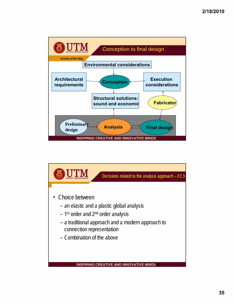
Type of Multistorey Steel Frame(semi-continuous and continuous)
Relationship between type of frame, analysis and design
Non Sway Frame Sway Frame (next page)First order
analysis
Elastic analysis Rigid-Plastic analysis
2nd order elastic or plastic analysis
75
Non sway mode buckling length used in member design
No internal moment and forces
redistribution
Internal forces and moment of up to 15% in the peak value can be
redistributed for class 1 or 2
Restrictions at all plastic hinge locations
λ ≤ 0.4[Afy/Nsd]0.5 in all columns containing plastic hinges
Type of Multistorey Steel Frame(semi-continuous and continuous)
Non Sway Frame (previous page)Sway Frame
Relationship between type of frame, analysis and design
2nd order analysis
Non-sway mode buckling lengths used in member
No internal moment and forces
redistribution
Internal forces and moment of up to 15% in the peak value can be redistributed for class
1 or 2
First order analysis
Elastic Global Analysis
Plastic Global Analysis
Next page
used in member design
Sway moments amplified by
Moment amplification of 1.2 in beams and beams-to-column connections
Non-sway mode buckling lengths used in member
design
Sway mode buckling lengths used in member design
( )[ ] 1crSd VV1 −−
Only if Vsd/Vcr ≤ 0.25

2/18/2010
39
Type of Multistorey Steel Frame(semi-continuous and continuous)
Non Sway Frame Sway Frame
Relationship between type of frame, analysis and design
(previous page) Sway Frame
Elastic Global Analysis Plastic Global Analysis
First order Rigid-Plastic analysis
Restrictions at all plastic hinge locations
Previous page
cross-section resistance checks
Second order analysis
λ ≤ 0.4[Afy/Nsd]0.5 in all columns containing plastic hinges
Internal moment and forces amplified by
Non-sway mode buckling lengths used in member design
( )[ ] 1crSd VV1 −−
resistance checks may not be needed.
Member resistance
Cross section resistance
Resistance of frame members subjected to a combination of compression, shear and bending moment
Buckling resistance
Laterally restrained
compression shear bending
Bending and compression
Bending and shear
Bending and shear
Laterally unrestrained
Flexural buckling
Flexural buckling and bending
78
g
Flexural buckling
Flexural buckling and bending
Lateral torsional buckling
Flexural buckling and Lateral torsional buckling
2/18/2010
40
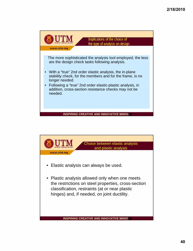
Implications of the choice of the type of analysis on design
The more sophisticated the analysis tool employed, the lessThe more sophisticated the analysis tool employed, the less are the design check tasks following analysis.
• With a “true” 2nd order elastic analysis, the in-plane stability check, for the members and for the frame, is no longer needed.
• Following a “true” 2nd order elastic-plastic analysis, in
79
addition, cross-section resistance checks may not be needed.
Choice between elastic analysis and plastic analysis
• Elastic analysis can always be used.
• Plastic analysis allowed only when one meets the restrictions on steel properties, cross-section classification, restraints (at or near plastic
80
hinges) and, if needed, on joint ductility.

2/18/2010
41
Choice of method of analysis/design
Factors which orient the choice:Factors which orient the choice:• type of structure : conception meeting architectural,
environmental and execution considerations and needs• availability of class 1 and 2 sections for plastic
analysis/design• other Eurocode requirements: 1st or 2nd order analysis?,
81
seismic design needed?• available software/designer’s experience
Frame classification
• Decision on the use of bracing or not influences sway classificationclassification
• Preliminary member sizing and estimates of column vertical loads: use to provide an indication of the sway classification using:
analysisorder 1st usecan :sway -Non : 1,0≤cr
Sd
VV
V
82
• Industrial portal frame: EC3 not suitable
effectsorder 2ndfor allowmust :Sway : 1,0>cr
SdV
V

2/18/2010
42
Sway frame : 2nd order effects
Alternatives to a “true” 2nd order analysis:1 t d l i “A lifi d S M t” th d • 1st order analysis + “Amplified Sway Moment” method when:
( )
( )crSdcr
Sd
crSdcr
Sd
VVVV
VVVV
−⇒≤
−⇒≤
11by forces allAmplify 20,0:design Plastic
11by MAmplify 25,0:design Elastic sway
83
• 1st order analysis + “Sway Mode Buckling Length” method (20% sway moment increase) - use not advised
1st order elastic analysis and relevant design checks
• Member sections and joints: ultimate design resistance:Member sections and joints: ultimate design resistance: redistribution possible
• In-plane and out-of plane beam-column stability check -usually with in-plane buckling lengths
• In-plane frame stability : accounted for by including 2nd order effects (when needed)B L t l t i l b kli• Beams: Lateral torsional buckling
• Others:Local buckling, Fire resistance etc.

2/18/2010
43
1st order plastic analysis and design
• Restrictions: (steel properties, section class etc.)• Rigid-plastic analysis and design:
braced non-sway frames, or unbraced of no more than 2 storeys (but see exception)
• Elastic-plastic analysis and design• Relevant design checks usually as for 1st order elastic design
85
Relevant design checks usually as for 1st order elastic design
2nd order plastic analysis and design
• Elastic plastic analysis and design• Elastic-plastic analysis and design• Rigid-plastic analysis and design with amplified forces -based on Merchant-
Rankine formula (use restricted)• Merchant-Rankine approach - not explicitly mentioned in EC3• Design checks depend on analysis tool, mostly as for 2nd order elastic
analysis
86

2/18/2010
44
Traditional approaches to design
• Pinned-Rigid Joints + elastic analysis• Rigid- plastic analysis/design : in some countries only:
Industrial portal frames and other frames of no more than 2 storeys
• “Wind-moment” + elastic analysis- no moment in joints for vertical loads only
87
j y- joints transmit moments due to wind
• Partial strength non-sway frames: plastic hinges at joints and in beam span
Traditional design approach
PRELIMINARY DESIGN OF MEMBERSJOINTS ASSUMED RIGID/PINNED
FRAME DESIGN O K ?
FRAME ANALYSISAND DESIGN
JOINTS ASSUMED RIGID/PINNED
NO
STOP
JOINT DESIGN
FRAME DESIGN O.K.?
YES

2/18/2010
45
Modern design approach
PRELIMINARY DESIGN OF MEMBERS
NOFRAME ANALYSIS
JOINT CHARACTERISATIONrigid/semi-rigid/pinned
AND JOINTS
YESSTOP
FRAME AND JOINT DESIGN O.K.?
AND DESIGN
Modern approach = consistent design : include joint response
• Joint response allowed for from the outset i.e. from the preliminary design tstage– Member sizing allows for joint response
• Better appreciation of structural behaviour• Can optimise overall costs, noting that
– a significant part of fabrication and erection costs is related to joints – the least weight frame solution is not necessarily the cheapest
90
– the least weight frame solution is not necessarily the cheapest
Note: If sway, advised to use “true” 2nd order analysis

2/18/2010
46
Design practice and its implications
R o le C a s e A C a s e B 1 C a s e B 2M e m b e rd i
E n g in e e r E n g in e e r F a b r ic a to rd e s ig nJ o in td e s ig n
F a b r ic a to r E n g in e e r F a b r ic a to r
F a b r ic a tio n F a b r ic a to r F a b r ic a to r F a b r ic a to r
• Case A sometimes leads to costly joint reinforcement if rigid joints have b d t d
Roles of the parties in the design and fabrication processes
91
been adopted• Case B1 requires the designer to be aware of the implications of joint
assumption on costs• Case B2 is ideal for a consistent design approach which aims at global
economy
Practical application of modern design approaches
Approaches easily integrated into current design practices:
• “Good guess stiffness” for semi-rigid joint + elastic analysis• “Fixity factor” approach in the traditional approach using elastic
analysis• Rigid-plastic analysis of non-sway frames using partial strength
92
Rigid plastic analysis of non sway frames using partial strength joints

2/18/2010
47
Summary
• Choice of type analysis/design: depends on type of structure, available tools , EC3 requirements, etc.
• The more sophisticated the analysis tool used, the lesser the design ULS checks
• Joint representation: a consistent approach can permit optimisation of costs
93
• Simple aids exist for integrating the « consistent approach » into traditional practice/breakdown of design tasks
Thank youThank you24 Feb 201024 Feb 2010