Fractography of Tire Tread Separations - Daws...
19
Paper No. 67 Fractography of Tire Tread Separations By: J. W. Daws, Ph.D., P.E. * Exponent Failure Analysis Associates Phoenix, AZ Presented at a meeting of the Rubber Division, American Chemical Society San Francisco, CA April 28-30, 2003 *Speaker
Transcript of Fractography of Tire Tread Separations - Daws...
Paper No. 67
Fractography of Tire Tread Separations
By: J. W. Daws, Ph.D., P.E. * Exponent Failure Analysis Associates
Phoenix, AZ
Presented at a meeting of the
Rubber Division, American Chemical Society
San Francisco, CA
April 28-30, 2003
*Speaker
FRACTOGRAPHY OF TIRE TREAD SEPARATION
John W. Daws, Ph.D., P.E.
Sr. Managing Engineer, Exponent Failure Analysis Associates 1850 W. Pinnacle Peak Rd., Phoenix, AZ 85027
ABSTRACT
In-service catastrophic radial tire failure is often a separation of the tread and outer steel belt from the tire casing and inner steel belt. These separations generally occur in the field at high temperature and high speed. In this study, tire belt-leaving-belt failures were created on a flat-track machine at high speed. The actual separations were captured on high-speed video to locate the origin of the belt-leaving-belt failure. Surfaces corresponding to the gradual cracking of the skim rubber along the edges of the belts, initiation of a belt-leaving-belt separation, high-speed tearing, and termination of the separation were described. The resulting fracture surfaces were then compared with surfaces found on tires that had failed in field service.
INTRODUCTION Tire failure analysis is usually focused on the mechanism of the separation of the outer steel belt from the tire casing and inner steel belt. The analyst must determine the point of origin of the separation from the appearance of the fracture surfaces. Smith1 described the microscopy of tire tread pieces gathered from roadsides in Arizona, California, and New Mexico. However, it is often the case in actual forensic investigation that the tire tread pieces are not recovered, leaving the analyst to deal with examining the inner steel belt’s exposed outer surface. This situation makes an understanding of the tire casing fracture surface important. In field tread separation events, the fracture surfaces can often be confounded by pre-tear polishing, post-separation skidding, and impact damage. The objective of this paper is to document the appearance of the outer skim surface of the inner steel belt resulting from a tread separation. Reference samples were created by cutting tires along the shoulders between the two steel belts and monitoring the tearing progression and belt-leaving-belt separation on a flat track machine at high speed and temperature. The resulting fracture surface starting and ending points were documented based on high-speed video data. The various fracture surfaces produced were then compared to surfaces from tires that had experienced a tread separation in actual use.
EXPERIMENTAL The tires used in this study were all P235/75R15 passenger car tires of the same construction. A number of tires were cut circumferentially about both shoulders to a depth of approximately 50 mm between the two steel belts that make up the crown reinforcement of the tire. The tread was then cut parallel to the wires of the outer steel belt in one location to generate a weak spot for the initiation of the belt-leaving-belt separation. This method of creating a belt-leaving-belt separation “on demand” was outlined by Fay et al.2 for use in vehicle testing.
Each tire was mounted in order to simulate a right side tire on a vehicle, assuming that the serial side of the tire would normally be mounted facing in. Each tire was inflated to 1.8 bar and loaded to 6670 N. Each tire was then accelerated on a flat track machine to a speed of 112 km/hour in 10 seconds [s] and run at that speed until the tread and outer steel belt separated from the tire casing. The belt-leaving-belt separation event was recorded on digital high-speed video at 1000 frames/s in order to capture the point of initiation of the separation as well as the direction of propagation. Separation initiation, separation propagation direction, and separation termination were all captured. The fracture surfaces on the outer skim of the casing inner steel belt from the resulting tread separations were examined and photographed. Fracture surfaces found on the inner skim surface of the tread and outer steel belt were obviously corresponding images of the tire casing surfaces. These tire casing fracture surfaces were compared to corresponding fracture surfaces from tires that had experienced field failures. In this study, the radial direction was taken to lie along the body ply cords of the casing. The circumferential direction was taken to lie perpendicular to the radial direction, also in the plane of the casing. All photographs are oriented so that the circumferential direction is horizontal and the radial direction is vertical. Also, for all photos, the serial side of the tire is at the bottom of the photograph and the opposite serial side is at the top.
OBSERVATIONS AND DISCUSSION
GENERAL FLAT TRACK TEST OBSERVATIONS During the course of the testing on the flat track machine, the resulting tread separations exhibited several consistent characteristics. First, the tire casing never lost pressure during the separation event. In general, the belt-leaving-belt separations occurred in less than 30 s for these tearing tests. The separated tread and outer steel belt pieces were always hot to the touch, and in some cases, there was heat-related discoloration of the rubber. Second, the tread separation always generated two triangular flaps at the region of initiation. This flap pair consisted of one flap, formed by a triangular piece of tread and outer steel belt bounded by a wire of the outer steel belt, that opened in a direction opposite to the direction of rotation of the tire. The second of the flaps was adjacent to the first along the same outer steel belt wire and opened in the
2
tire’s direction of rotation. The first of these has been called a “leading edge flap” because its triangular end at the tire shoulder points in the direction of tire rotation. The second flap is normally called a “trailing edge flap” for similar reasons. Another observation from the machine tests is that the leading edge flap propagates most of the way around the circumference of the tire while the trailing edge flap experiences only a small amount of tear propagation. This result is reasonable since the leading edge flap tends to be torn open on contact with the machine frame (or the vehicle body, for a field tire) at each revolution of the tire, while the trailing edge flap is pushed closed, and, in the case of the machine test tires, both types of flaps were equally likely. This is because the cuts used to generate the initiation of flaps resulted in a situation wherein both flaps were created simultaneously. During the initiation of the flaps, centrifugal force and stresses associated with the change of curvature of the tread while in contact with the road surface cause the tearing of the skim rubber between the two steel belts. When the flaps reach a certain size, however, the leading edge flap is also torn open by forces resulting from contact with the machine frame. The trailing edge flap is pushed closed by those same forces. The tearing of the flaps from the tire casing normally begins when the flap widths approach the width of the attached tread.
FRACTURE SURFACE OBSERVATIONS General. – Four main types of fracture surfaces were observed. The first of these was found circumferentially on both edges of the uncut regions of skim rubber between the two steel belts. The second type of crack surface observed was associated with the centrifugal force generation of the flaps at the initiation of the belt-leaving-belt separation. The third crack region observed was associated with the rapid tearing of the tread and outer steel belt away from the inner steel belt. The fourth crack region observed was associated with the final separation. Each of these is shown in the accompanying figures and described in the following sections. Edge crack generation. – Smith1 called the circumferential cracks “ring tears”, and associated them with small-scale cyclic deformations of the belt edges. These edge cracks propagate radially into the skim rubber. Since the ends of the steel belt wires are recognized to be the initiation points for these cracks, they develop simultaneously around the circumference of the steel belt edge on both sides of the tire (Huang and Yeoh3). Crack growth rates depend upon the tire design and materials used, but initial radial growth rates in new tires are assumed to be very small, probably much less than 0.1 nm/rev. As the cracks grow in the radial direction, the crack growth rate is thought to evolve to a nearly constant level for the first 5-20 mm of depth (Lake4). As the crack depth progresses beyond this level, the growth rate accelerates. These edge cracks are normally observed in belt-leaving-belt field separations, but they are often polished smooth as tire operation continues because of the slow growth very near the edge of the steel belt.
3
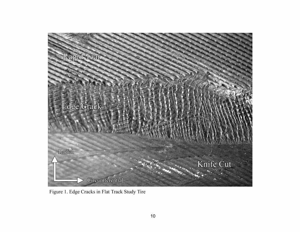
Figure 1 shows a close up view of the edge cracks that were typical of those generated on the flat track tests. Figure 1 shows clearly, in the lower part of the photograph, the knife cut region that was introduced in the skim rubber between the two steel belts in order to facilitate the tread separation. The edge cracks grew from the edge of the knife cut into the skim rubber between the two steel belts. Because an artificial crack of 50-mm depth had been introduced between the belts on both sides of the tire, these edge cracks developed and progressed very quickly in the presence of high strain energy density. Edge crack growth rates as high as 0.1 mm/rev were observed. The rapid tear zone is situated above the edge crack region and fills the top third of Figure 1.
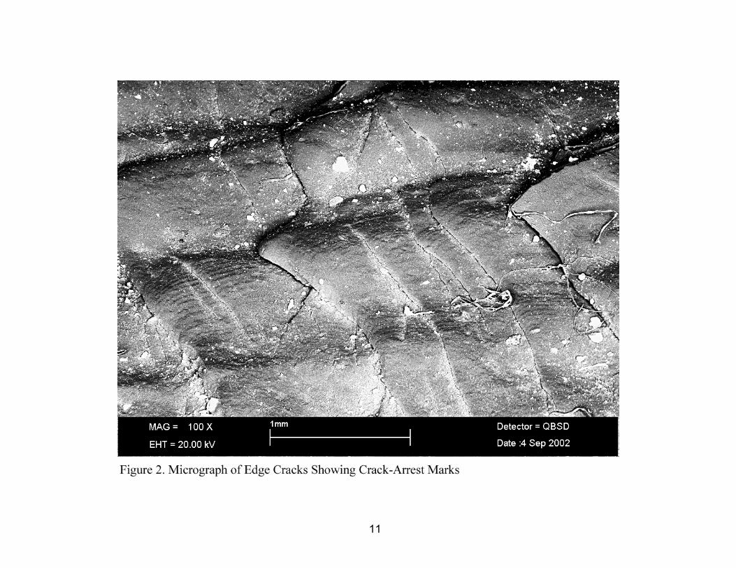
Figure 2 shows a micrograph of the edge cracks. Crack-arrest marks, or beach marks, can be clearly seen running perpendicular to the direction of crack growth. These beach marks denote the crack tip front at a particular time. Note that the crack-arrest marks terminate at what appear to be ridges or radially-oriented steps. These ridges separate regions where the crack growth from each initiation point occurs on a slightly different path within the bulk of the skim rubber. In the case of field tires, these edge cracks grow from the ends of the wire strands that make up the steel belt reinforcement because the steel wire is not brass-plated at the cut ends. In this experiment, the edge cracks grew from points where the overlap of inner and outer belt wires created stress concentrations in the skim rubber at the cut edge.
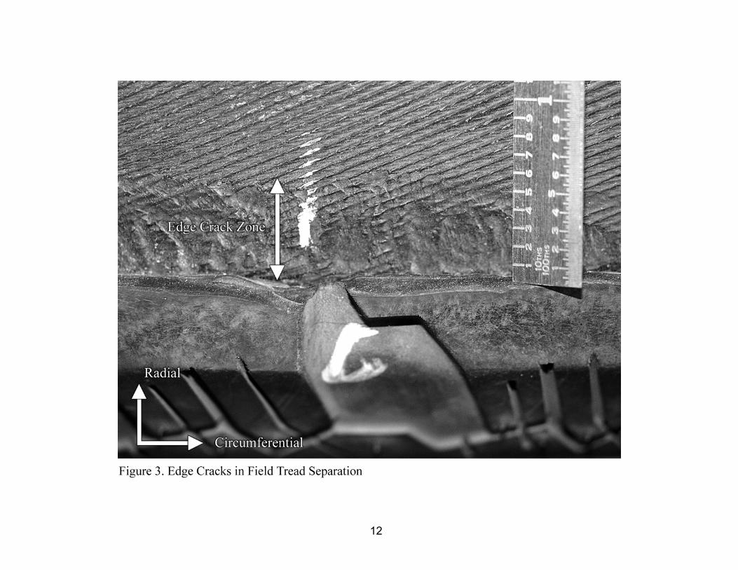
Figure 3 shows the zone of edge cracking in a tire that experienced a field-service tread separation. In this case, the edge cracks grow in fatigue from the edge of the outer steel belt into the skim rubber between the two steel belts. Since the initial fatigue crack growth rate is very low in field tires, it is normal to have polishing of the edge crack surfaces and a corresponding reduction in the sharpness of the radially-oriented tear ridges that characterize these cracks. The relative movement of the crack surfaces is caused by the strains generated when the tread is in road contact during each rotation.
The depth of these cracks in both the flat track samples and in field tires varies around the circumference of the tire. As noted by Smith1, the cracks are generally deeper on the shoulder of the tire where the top steel wires point into the road contact. Also, circumferential variation in crack depth on a given side of the tire is caused by stress state variations in the tire resulting from variations in the rubber dimensions that occur naturally in the tire building process and by the statistical variation in crack initiation and early crack development. As the cracks progress more deeply into the skim rubber in the radial direction, the crack growth per revolution accelerates. The normal outcome of this characteristic is the generation of one or two large thumbnail-shaped pockets between the two steel belts. These large pockets are generally the location at which the tread separation can initiate in field tires. The current experiment shows that the development of these pockets can be extremely rapid in field tires once the crack depth moves beyond the approximate 5-20 mm boundary of constant growth rate. For crack depths beyond 50 mm, the current experiment showed cracks propagating at rates approaching 0.1 mm/rev, which would be on the order of 35 mm/km of vehicle travel.
4
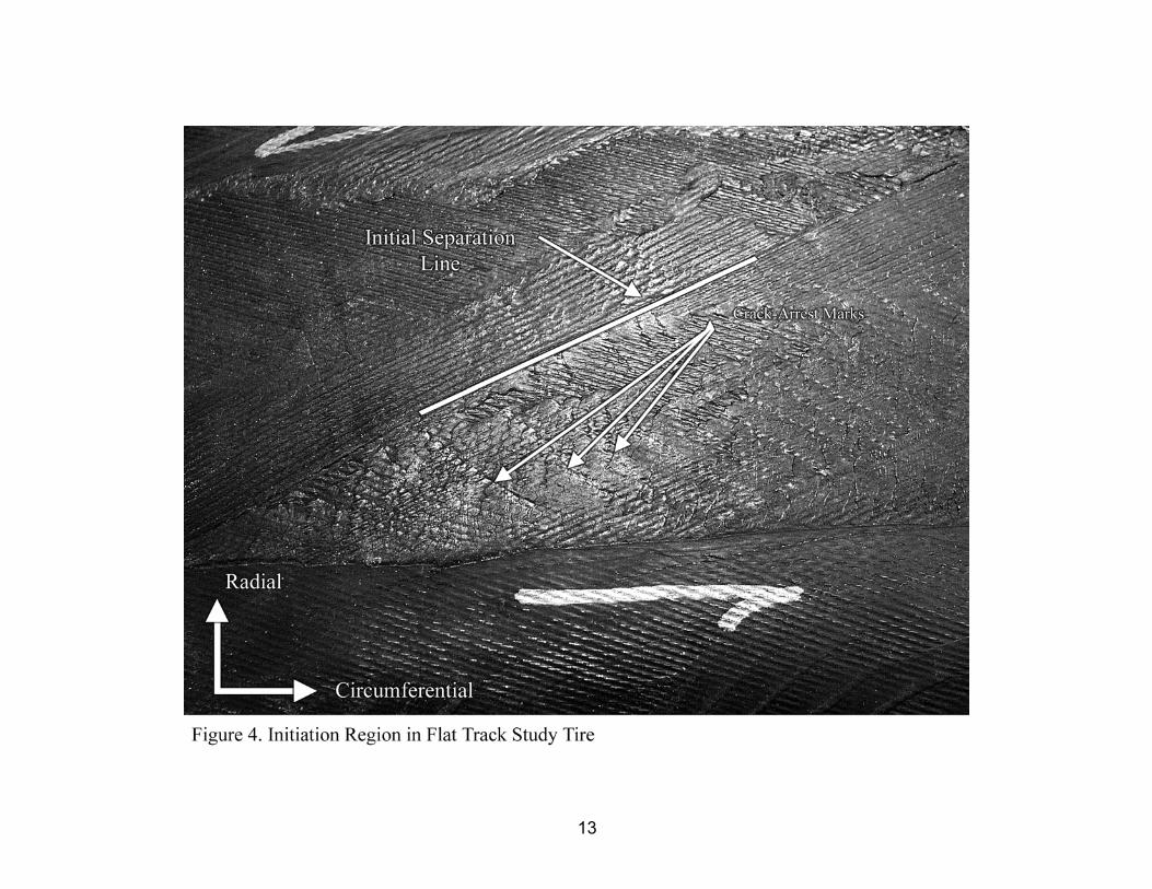
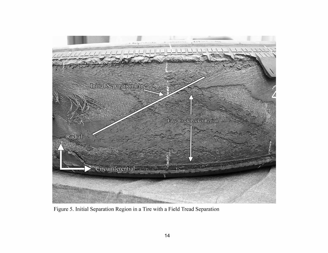
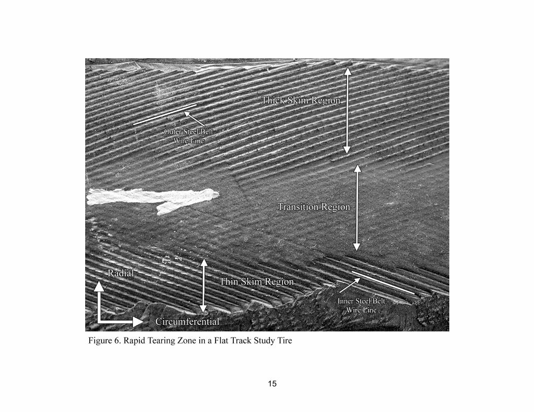
Flap initiation. – The region at the point of initiation of the flap tips is torn during operation by centrifugal and contact patch stresses. In this region, distinct beach marks are observed. These marks go from the separation line to the belt edges at the shoulders of the tire. Relative to the tip of the flap, the beach marks produce arcs, showing that the flap edge along the tire’s shoulder is being pulled further during each tear than is the flap edge along the separation line, which is consistent with the tire having curvature across the tread area. The tear propagation rate of these cracks along the tire’s circumference was on the order of 10 mm/rev in the current experiment. Figure 4 shows one of the flap initiation zones from flat track test sample. The knife cut region can be clearly seen in the lower portion of the photograph. The initial separation line, which follows the wire line of the outer steel belt, is highlighted for clarity. The horizontal arrow in the photograph shows the direction of propagation of the crack for the flap tip below the separation line. The beach marks are well-defined in one of the triangular regions under the flaps in this example. Figure 5 shows the initial separation line for flap formation from a tire that had experienced a field tread separation. Below and to the right of the separation line is the thumbnail pocket that was developed by the edge cracks growing and linking together under fatigue loading. In this particular case, the edge crack pocket extended about 85 percent of the way across the tire’s tread area before the flaps formed and the tread and outer steel belt separated. As would be expected, there was a significant amount of polishing at the tire shoulder due to the large interfacial movement that occurs in a pocket of this size, as well as other distortion of the crack surfaces near the tire centerline. In fact, the flap tips in this case did not generate the characteristic beach marks, because once the tread and outer steel belt broke at the tire shoulder, the flap was already separated for nearly the full width of the tire. As seen in the flat track studies, rapid tearing of the flap normally begins at the point where the flap width is approximately equal to the tread width. Rapid tearing. – Once the flaps have separated across the entire tread width at one location, the tear crack propagation in the skim rubber between the two belts occurs rapidly. When the leading edge flap experiences contact with external surfaces, the tear propagates at rates on the order of 100 mm/rev or higher. The skim rubber in this region will normally peel close to the inner steel belt on one half of the separation region and close to the outer steel belt on the other half. The resulting thick-thin aspect of the skim rubber remaining on the outer surface of the inner steel belt is very distinctive. Figure 6 shows this type of surface from one of the flat track study tires. The dividing line between the thick and thin skim is a transition region that normally follows the centerline of the tread. The width of the transition region was highly variable in this study.
The direction of propagation of the tear and the tire’s rotational direction determine whether the skim remaining on the outer surface of the inner belt will be thick or thin on the serial and opposite serial sides. As seen in Figure 6, the region of thin skim is the one showing wire lines from the inner steel belt in the lower portion of the photograph, while the region of thick skim in the upper portion of the photograph shows wire lines from the outer steel belt. The
5
horizontal arrow in the photograph shows the direction of propagation of the crack. In the flat track study, the thick skim zone on the inner steel belt surface of the casing is on the opposite serial side of the tire for the leading edge flap. The trailing edge flap produces the thick skim on the serial side of the tire. Since the flat track study tires were run as right side tires, it follows that the locations of the thick and thin skim zones are reversed in relation to the serial and opposite serial sides if the tires are run on the left side.
The locations of the thick and thin skim arise due to the compound curvature of the tire’s surface. When the tread and outer steel belt are pulled off the inflated casing, the edge of the crack forms an arc in the direction of propagation of the tear. This arc has the appearance of a “C” with the open end toward the direction of crack propagation. In the case of the leading edge flap on a right side tire, the outer steel wires pull out of the skim rubber on the opposite serial side of the tire where they align with the edge of the arc of the crack front. On the serial side of the tire, the arc of the crack front aligns with the inner steel belt wires, causing the skim rubber to be pulled out of the wires in that belt. For the trailing edge flap, the propagation direction is opposite to that of the leading edge flap and therefore the crack front arc and the thick and thin skim locations are reversed.
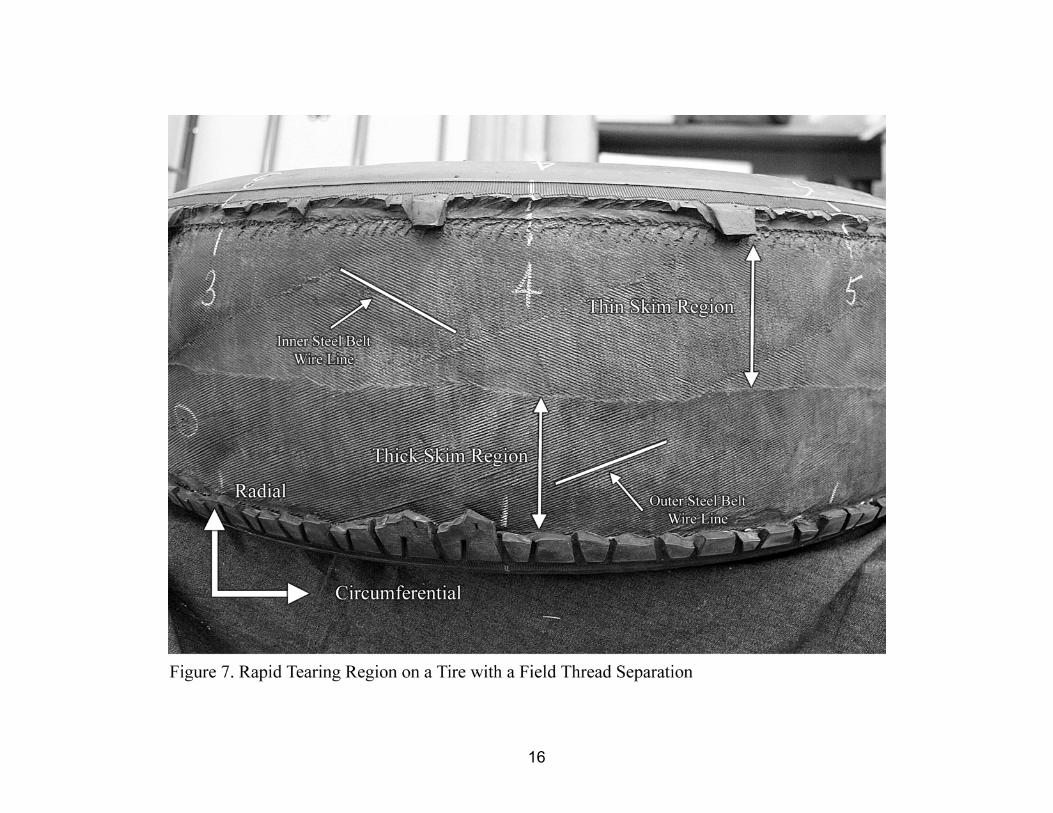
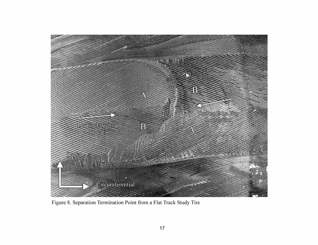
Figure 7 shows the rapid tear region on a tire that experienced a field tread separation. This particular tire was from the left side of a vehicle, so the thick and thin skim regions are reversed from that of the flat track study tires. Note that the transition region is nonexistent in this particular tire. One would also expect that, for tires built for right-hand drive countries, the skim patterns would be reversed from those found in left-hand drive countries since the steel belt wire angles are normally reversed for the inner and outer steel belts. Termination/Separation. – The tread and outer steel belt separate completely from the tire casing when the leading and trailing edge flaps meet. The point is marked by a distinctive reversal of the skim thicknesses in the rapid tearing region. This characteristic pattern follows naturally from the patterns observed in the rapid tearing region previously discussed. Figure 8 shows the separation termination pattern from one of the flat track study tires. The flap propagation directions are indicated on the photograph. As previously noted, the skim patterns for the two flaps will be opposite. This is shown clearly in Figure 8, where the pattern noted “A” is on the opposite serial side for the leading edge flap and on the serial side for the trailing edge flap. Figure 9 shows the separation region on a tire that experienced a field tread separation. The distinctive pattern indicating the separation termination point is found in the middle of the matching patterns shown by “A” and “B”. In the case of this tire, the leading edge flap originated at the lower right extremity of the photograph. The trailing edge flap experienced very little growth as the leading edge flap progressed completely around the tire.
6
CONCLUSIONS
The following conclusions are drawn from the analysis of tire tread belt separations created on a flat track machine and comparison of those fracture surfaces with those found in field tires:
1. Edge cracks in the skim rubber between the two steel belts of a radial tire leave characteristic radial tear ridges.
2. The depth of the edge cracks between the two steel belts is variable around the circumference of the tire.
3. The propagation rate of the edge cracks in the radial direction starts out at a very low level and becomes very high as the final separation becomes imminent. Propagation rates in the radial direction at 50 mm of crack depth as high as 0.1 mm/rev were observed in this experiment.
4. The tread separation initiation region is characterized by a line along the outer steel belt wires bounding two triangular regions that were created by the generation of flaps. There are often beach marks present in one or both of the triangular regions.
5. The leading edge flap normally propagates circumferentially at a higher rate than the trailing edge flap due to contact with stationary surfaces.
6. The rapid tearing of the skim between the two steel belts begins when the flaps attain a width close to the full tread width.
7. The rapid tearing region is characterized by distinct patterns of thick and thin skim that depend on the rotation of the tire and the flap propagation direction.
8. The separation termination point is characterized by a distinctive reversal of the skim thickness pattern in the rapid tear region.
SUMMARY
Fracture surfaces were evaluated from tire belt-leaving-belt separations that were created, monitored, and photographed while running on a flat track machine. High-speed video data from each flat track separation test was used to identify the location of the start point, end point, and the propagation direction of the resulting flaps. Close visual inspection was used to identify four characteristic regions on the fracture surfaces. The four regions were identified as edge cracks (ring tears, as previously identified by Smith1), the initial separation line at flap formation, the rapid tearing region, and the tread separation termination point. The characteristics of these features were cataloged and compared to fracture surfaces observed on field tires. This analysis shows that the fractography of the skim rubber surface on the tire casing in a belt-leaving-belt separation can be used to determine the origin and termination points of the separation.
7
REFERENCES
1R.W. Smith, Rubber Chem. Technol., 70, 283 (1997). 2Fay, et al., SAE Paper No. 1999-01-0447. 3Y.S. Huang and O.H. Yeoh, Rubber Chem. Technol., 62, 709 (1989). 4G.J. Lake, Rubber Chem. Technol., 74, 509 (2001).
8
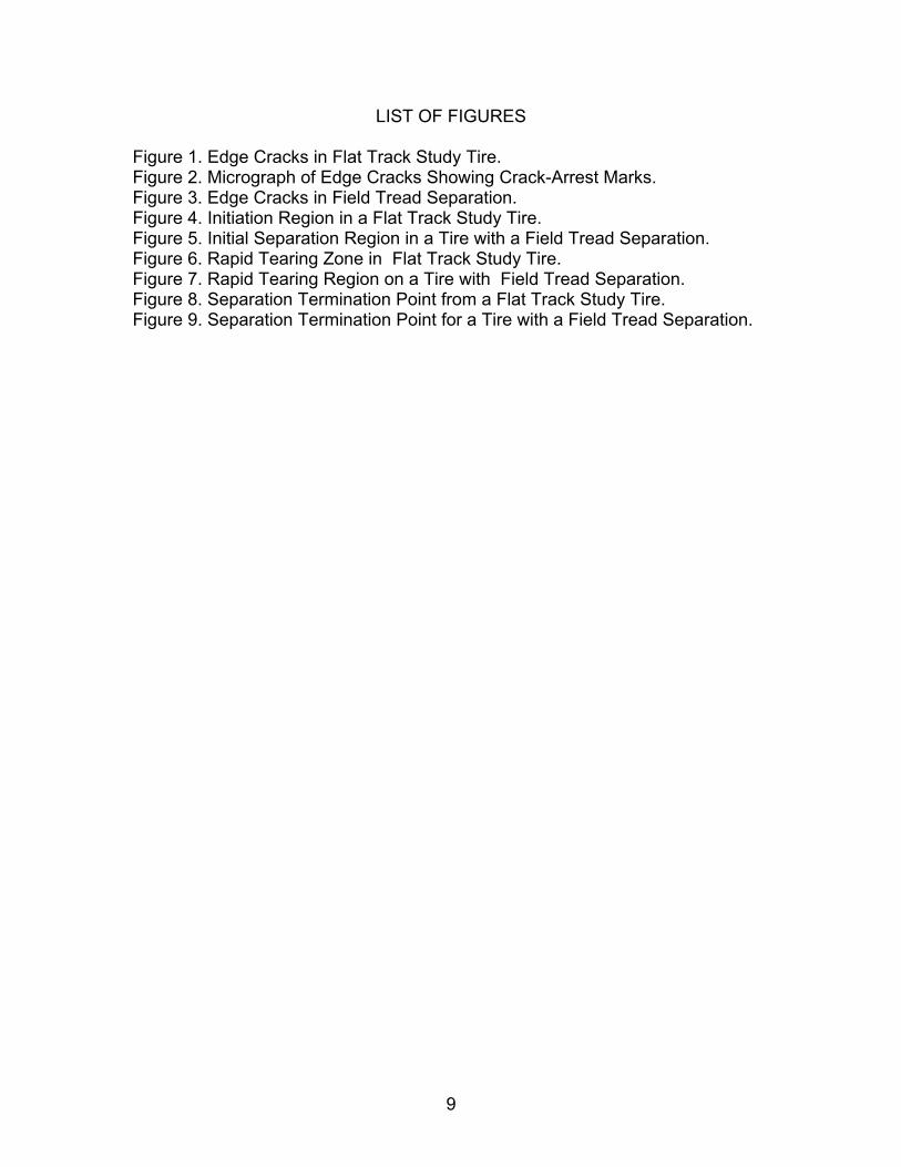
LIST OF FIGURES Figure 1. Edge Cracks in Flat Track Study Tire. Figure 2. Micrograph of Edge Cracks Showing Crack-Arrest Marks. Figure 3. Edge Cracks in Field Tread Separation. Figure 4. Initiation Region in a Flat Track Study Tire. Figure 5. Initial Separation Region in a Tire with a Field Tread Separation. Figure 6. Rapid Tearing Zone in Flat Track Study Tire. Figure 7. Rapid Tearing Region on a Tire with Field Tread Separation. Figure 8. Separation Termination Point from a Flat Track Study Tire. Figure 9. Separation Termination Point for a Tire with a Field Tread Separation.
9
10
11
12
13
14
15
16
17

18