FPGA Technology Mapping Dr. Philip Brisk Department of Computer Science and Engineering University...
46
FPGA Technology Mapping Dr. Philip Brisk Department of Computer Science and Engineering University of California, Riverside CS 223
-
Upload
hayden-tapley -
Category
Documents
-
view
214 -
download
0
Transcript of FPGA Technology Mapping Dr. Philip Brisk Department of Computer Science and Engineering University...

FPGA Technology Mapping
Dr. Philip BriskDepartment of Computer Science and Engineering
University of California, Riverside
CS 223

Example

Theoretical Results
• Minimize Number of Logic Stages– Polynomial-time
• Minimize Total Number of LUTs (Area)– NP-Complete
• Minimize Power Consumption– NP-Complete
DAG Representation
• Since LUTs are reconfigurable, we don’t need to worry about the logic function of each gate during mapping

K-Feasible Cuts and LUT Mapping

Example: Node Duplication

FlowMap: An Optimal Technology Mapping Algorithm for Delay Optimization in Lookup-
Table Based FPGA Designs
Jason Cong and Yuzheng DingIEEE Trans. CAD 13(1): 1-12, Jan. 1994

Cuts in a Directed Acyclic Graph (DAG)
A cut is K-feasible if:
This cut is 3-feasible
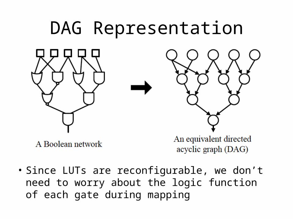
Edge Cut Size
• Each edge has non-negative capacity
• The edge cut size is the sum of the capacities of the forward edges that cross the cut
• All edge capacities are assumed to be 1

Example: Edge-cut size is 10

Volume and Height
• The volume of a cut is the number of vertices in X:
• Given an assignment of labels to vertices, the height of a cut is the largest label in X

Example: Volume=9, Height=2

FlowMap Algorithm (Overview)
• Labeling Phase– Computes a label for each node reflecting the
level of the K-LUT that implements that node in a depth-optimal mapping solution
• Mapping Phase– Generates the K-LUT mapping solution based on
node labels computed in the first phase

Subnetwork of a Node
• For node t, let Nt denote the subnetwork consisting of every vertex s, such that there is a path from s to t

Conversion to a Network Nt
• For node t, let Nt denote the subnetwork consisting of every vertex s, such that there is a path from s to t
• We can ignore the logic function of each gate

Intuition
• Let LUT(t) represent a K-LUT that produces an output at node t
• Define a K-feasible cut where– denotes the set of nodes in LUT(t)– denotes the remaining nodes in– K-feasibility is ensured since LUT(t) has < K inputs
• If u has the maximum label in , then in the optimal mapping,

Minimizing the Level of LUT(t)
• There may be many K-feasible cuts in • Lemma 1. Find the one that minimizes height!
• Note: This definition enumerates all K-feasible cuts at t– Key contribution: This can be done in O(Km) time,
where m is the number of edges in

Example
• You get the existence of the 3-feasible cut in part (c) for free. • Figuring out how to compute it is the hard part!

Lemma 2
• Proof Strategy1. Prove2. Prove
Consult the paper for details

Algorithmic Strategy
• Check if there is a K-feasible cut of height in – If so, pack along with the nodes in in the
second phase of the algorithm. • Otherwise, the minimum height among all K-
feasible cuts in is is ,, and is one such cut.– If so, use a new K-LUT for in the next phase.

How to efficiently test if has a K-feasible cut of height p – 1?
• Let p be the maximum label among all nodes of input(t)
• Equivalently, p is the maximum label of all nodes that belong to
• Collapse all nodes in with label > p along with t into a single sink t’; call the new network

More Theory
• Construct another network from – Details to follow…
• has a cut whose edge cut-size is no more than K if the max. flow in is at most K

Example
…
…

Algorithmic Strategy (Recap)
• Check if there is a K-feasible cut of height in – If so, pack along with the nodes in in the
second phase of the algorithm. • Otherwise, the minimum height among all K-
feasible cuts in is is ,, and is one such cut.– If so, use a new K-LUT for in the next phase.

Labeling Algorithm for K-LUTs
• For each node t in the DAG, taken in topological order– Let p be the max. label among all nodes of – Build networks , , and – Compute the maximum flow in – If the maximum flow is less than K, then:– Otherwise
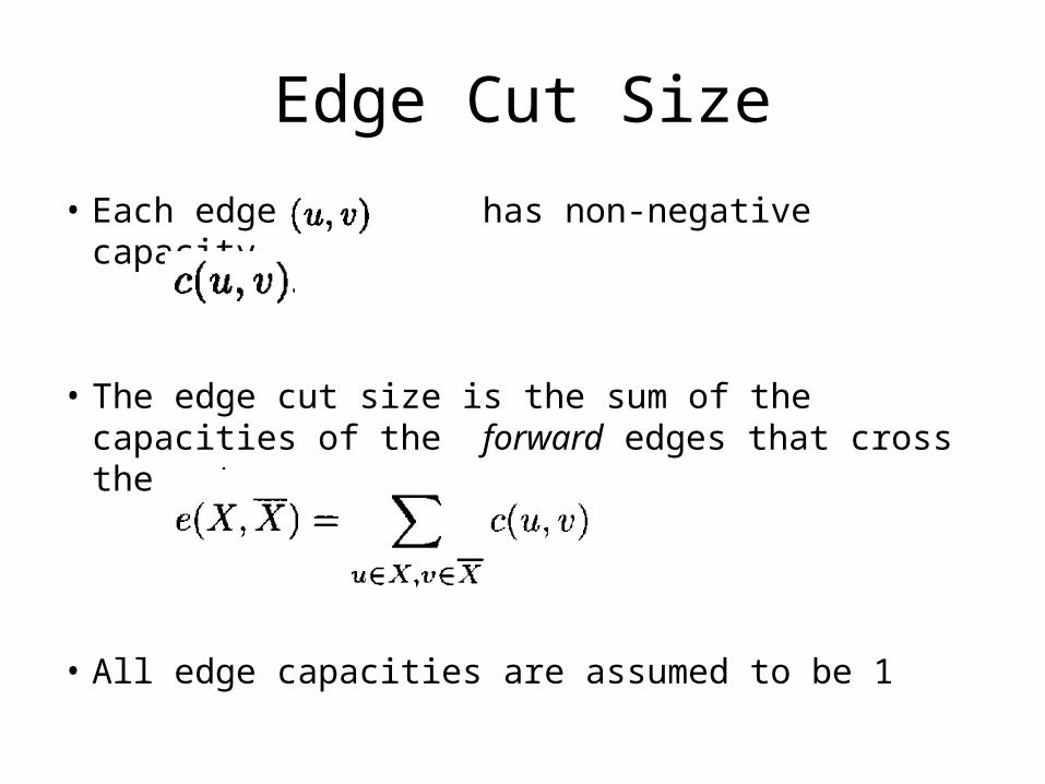
Summary of Theoretical Results

FlowMap Algorithm

Post-processing for Area Reduction

Post-processing for Area Reduction

Post-processing for Area Reduction

WireMap: FPGA Technology Mapping for Improved Routability and Enhanced LUT
Merging
S. Jang, B. Chan, K. Chung, and A. MishchenkoACM TRETS 2(2): article #14, June, 2009

And-Inverter Graph (AIG)
https://en.wikipedia.org/wiki/And-inverter_graph
ANDANDAND
ANDAND
INV
INVINV
INV
INVINV

Generic FPGA Technology Mapping

Cut Enumeration
• The set of K-feasible cuts for an AND node n with predecessor nodes n1 and n2
• Let A and B be two sets of cuts
Cut Enumeration
• Process vertices in topological order to ensure that cut sets for n1 and n2 are known before computing the cut set for n– The CUT set of an AND node is computed by
merging the CUT sets of its predecessors and adding the trivial cut (containing just n) while keeping only the K-feasible cuts
– Remove dominated cuts– Each AIG node is a 2-input AND

Depth-Oriented Mapping• Keep the node at each level that minimizes
depth (e.g., FlowMap)

Area Recovery
• Depth minimization may cause area duplication– Multiple cuts cover an AIG node– Increases LUT count
// Area Flow• Global View• Selects cuts with more shared logic
// Exact Local Area• Local View• Minimizes area exactly at each node
Area Flow
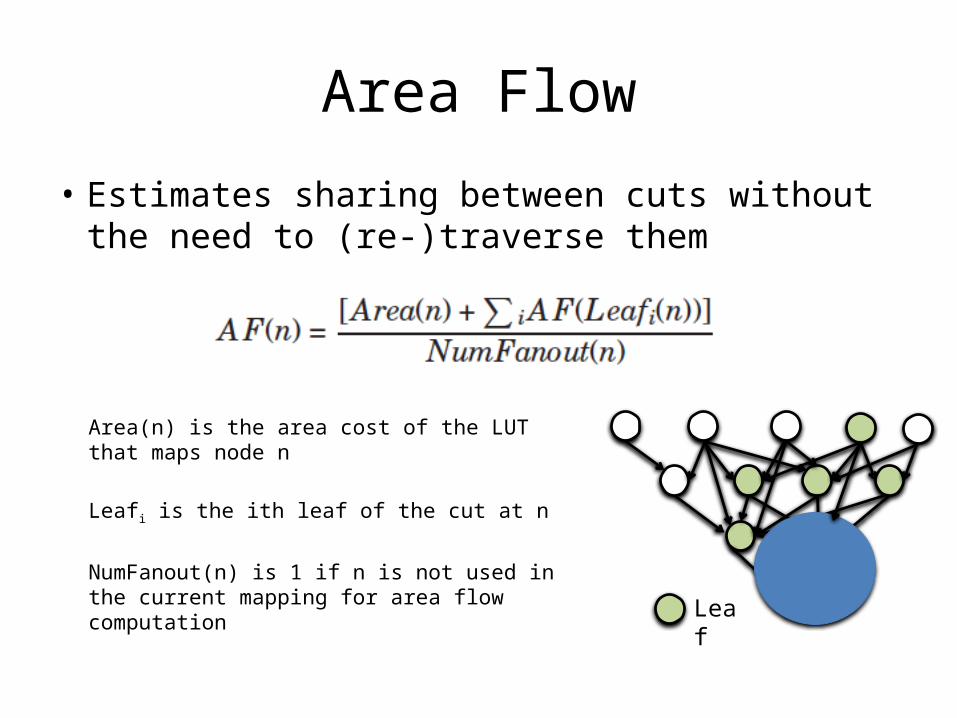
• Estimates sharing between cuts without the need to (re-)traverse them
Area(n) is the area cost of the LUT that maps node n
Leafi is the ith leaf of the cut at n
NumFanout(n) is 1 if n is not used in the current mapping for area flow computation
nLeaf

Local View
• The exact local area of the current node is the area added to the mapping by using the current node
• Recursively compute the number of LUTs in the max. fanout free cone (MFFC) of the current node– Use a fast local DFS traversal
Recursive Calls
n

Producing a Mapped Network
• Assume one K-feasible representative cut is computed for each node

WireMap
• Objective– Reduce the number of LUT-to-LUT connections in
addition to area reduction
• Rationale– Fewer nets will help the placer to generate a
solution with reduced wirelength

Global View Heuristic
• Area Flow (from previous slide)
• Edge Flow (new idea)
Area(n) is the area cost of the LUT that maps node n
Edge(n) is the number of fanin edges to the LUT that maps node n

Global Edge/Area Recovery Alg.
Find all cuts with min. area
Use edge flow as tiebreaker
No recursion; use the saved edgeflow computed at each predecessor node
nLeaf

Local View
• The exact local area (edge count) of the current node is the area (edge count) added to the mapping by using the current node
• Recursively compute the number (edge count) of LUTs in the max. fanout free cone (MFFC) of the current node– Use a fast local DFS traversal
Recursive Calls
n

Local View Algorithm
Find all cuts that minimize the exact area; use the exact edge count as a tiebreaker
Edge count of a cut depends if the cut is representative of the node in the mapping• If so, reference the node and the leaves
of its representative cut
Pointer manipulation in function calls (not shown)

WireMap Algorithm
Xilinx Virtex-5Dual Output LUT