FPGA Implementation of a Flexible and Synthesizable …ijrece.com/Pdfs/V1-I2-P8.pdf · FFT Fast...
5
ISSN: 2321-5593 (Online) IJRECE Vol–1, Issue-2, Oct - Nov, 2013 ISSN: 2321-032X(Print) 58 International Journal of Research in Electronics & Communication Engineering www.ijrece.com FPGA Implementation of a Flexible and Synthesizable FFT Processor 1 Syed Hussain Basha, 2 B.Rajkumar 1 M.Tech Student, 2 Asst.professor 1,2 Dept. Of Electronics &Communication Engineering 1,2 Shaddan College Of Engineering Abstract: This paper presents the current stage development of a Fast Fourier Transform (FFT) processor in FPGA. This processor uses fixed point numeric representation. It`s main use is to develop an fully parameterizable processor. It is also used in several applications such as classification of algorithms and communication system. An open source prototype core has been developed and it can perform a complete FFT transform using radix-2 and radix-4 as it is an parameterizable processor in a way that the number of bits, fixed point position and number of points computed in the FFT can be easily changed. Hence with the implementation of radix-4 DIT- FFT of 64 points with an data length of 256 bits the time consumption is very low. Results and details of implementation for both radix-2 32 bit DIF-FFT and radix-4 64 point DIT- FFT are shown. Keywords: FFT,VHDL Language, Implementation, Synthesis, Comparison. 1. INTRODUCTION The Fast Fourier Transform (FFT) is simply a fast computational efficient way to calculate DFT. The most popular tool for the analysis of Fourier is called Discrete Fourier Transform (DFT).Hence a lot of computational complexity is found in this DFT hence which proposed to an efficient algorithm for the calculation of DFT i.e.; FFT Fast Fourier Transform. Using traditional programming languages they are designed by focusing on implementation in dedicated hardware. The design of FFT processor is done using the VHDL(VHSIC Hardware Description Language) language. The FFT processor developed in this article is more flexible and hence the fixed point numerical point representation of data such as number of bits and number of points can e changed, hence allowing this the same FFT processor can be used in a variety of applications. FFT`s are composed by several elementary operations carried out with all the samples of a signal. This operation is called butterfly and is composed of Multiplications and summations. The butterfly is normally performed with 2 or 4 samples of a signal at a time, and is called radix-2 or radix-4, respectively. In this Article we have been implemented the 2. FFT IMPLEMENTATION The algorithm language used in the implementation of FFT is the VHDL language. The term Decimation in Frequency DIF-FFT indicates that the samples are in normal order and the output will be in bit reversal order. Hence in the Decimation in time DIT-FFT the inputs will be given in bit reversal order and the output will be in normal order. Already the term radix-2 indicates that the DFT was
Transcript of FPGA Implementation of a Flexible and Synthesizable …ijrece.com/Pdfs/V1-I2-P8.pdf · FFT Fast...

ISSN: 2321-5593 (Online) IJRECE Vol–1, Issue-2, Oct - Nov, 2013 ISSN: 2321-032X(Print)
58 International Journal of Research in Electronics & Communication Engineering www.ijrece.com
FPGA Implementation of a Flexible and Synthesizable FFT Processor
1Syed Hussain Basha, 2B.Rajkumar 1M.Tech Student, 2Asst.professor
1,2Dept. Of Electronics &Communication Engineering 1,2Shaddan College Of Engineering
Abstract: This paper presents the current stage development of a Fast Fourier Transform (FFT) processor in FPGA. This processor uses fixed point numeric representation. It`s main use is to develop an fully parameterizable processor. It is also used in several applications such as classification of algorithms and communication system. An open source prototype core has been developed and it can perform a complete FFT transform using radix-2 and radix-4 as it is an parameterizable processor in a way that the number of bits, fixed point position and number of points computed in the FFT can be easily changed. Hence with the implementation of radix-4 DIT- FFT of 64 points with an data length of 256 bits the time consumption is very low. Results and details of implementation for both radix-2 32 bit DIF-FFT and radix-4 64 point DIT-FFT are shown. Keywords: FFT,VHDL Language, Implementation, Synthesis, Comparison. 1. INTRODUCTION The Fast Fourier Transform (FFT) is simply a fast computational efficient way to calculate DFT. The most popular tool for the analysis of Fourier is called Discrete Fourier Transform (DFT).Hence a lot of computational complexity is found in this DFT hence which proposed to an efficient
algorithm for the calculation of DFT i.e.; FFT Fast Fourier Transform. Using traditional programming languages they are designed by focusing on implementation in dedicated hardware. The design of FFT processor is done using the VHDL(VHSIC Hardware Description Language) language. The FFT processor developed in this article is more flexible and hence the fixed point numerical point representation of data such as number of bits and number of points can e changed, hence allowing this the same FFT processor can be used in a variety of applications. FFT`s are composed by several elementary operations carried out with all the samples of a signal. This operation is called butterfly and is composed of Multiplications and summations. The butterfly is normally performed with 2 or 4 samples of a signal at a time, and is called radix-2 or radix-4, respectively. In this Article we have been implemented the 2. FFT IMPLEMENTATION The algorithm language used in the implementation of FFT is the VHDL language. The term Decimation in Frequency DIF-FFT indicates that the samples are in normal order and the output will be in bit reversal order. Hence in the Decimation in time DIT-FFT the inputs will be given in bit reversal order and the output will be in normal order. Already the term radix-2 indicates that the DFT was

ISSN: 2321-5593 (Online) IJRECE Vol–1, Issue-2, Oct - Nov, 2013 ISSN: 2321-032X(Print)
www.ijrece.com International Journal of Research in Electronics & Communication Engineering 59
decomposed into two operations that are performed in parallel; the butterflies of FFT will be performed using two samples of each time. The processor description of FFT in VHDL has embraced the organization of internal components, shown in Fig 1. The following subsections describe the functions of each of these components.
Figure 1. Internal Organization of the
FFT processor. A. Input and output Signals CLK: is the input pin that serves as synchronizer, or time base for the processor. RST: is an input pin that restarts the FFT algorithm with radix-2 32bits DIF-FFT and radix-4 64 point DIT-FFT with a data length of 256 bits is shown operation at any time. When this pin is at a high level (logic level 1) registers are assume their initial values and the machinery of states that make up the components go to their initial states. START: it is an input pin used to signal the Processor when to start its operation. RE_DATA and IM_DATA: is a set of input pins that represent the real and imaginary part of the input data. The number of pins is corresponding to the number of bits of data and can be changed before the compilation. Before you start the transfer of the data there is a startup period of internal components. After this period, a sample is read and stored in the internal memory of the processor to
each clock cycle.X RE_OUT and IM_OUT: is a set of output pins by where the real and imaginary part of the resulting data are transferred. The data from the internal memory of the processor are transferred to each clock cycle. B. Internal Blocks These blocks were designed as machines of states, because this technique allows good predictability of issues found in hardware design (10). INPUT: is the block responsible for storing the input data in the internal memory. The beginning of the operation the block ARBITER signals for this block start their operation. He receives the data and generates the correct address to store in memory, i.e. this block performs the decimation in time. In future this block will be implemented with a protocol, to improve the portability of the project. BUTTERFLY: this block is the processor core, he is able to make processed in any size. More details on this block are given in Section III. OUTPUT: after the implementation of the algorithm for FFT this block starts the process of transfer of the resulting data, transferring a given per clock cycle. MEMORY: Is Composed By Two Block s Storage, one for the real part and another for the imaginary part of the data. He was implemented so that the synthesis tool automatically maps the code to the internal memory of the FPGA. For this reason, it was used the tool of Quartus II synthesis call Changes (11). ARBITER: only one block must be in operation for each time. In This way, this block is responsible for managing the other
ISSN: 2321-5593 (Online) IJRECE Vol–1, Issue-2, Oct - Nov, 2013 ISSN: 2321-032X(Print)
60 International Journal of Research in Electronics & Communication Engineering www.ijrece.com
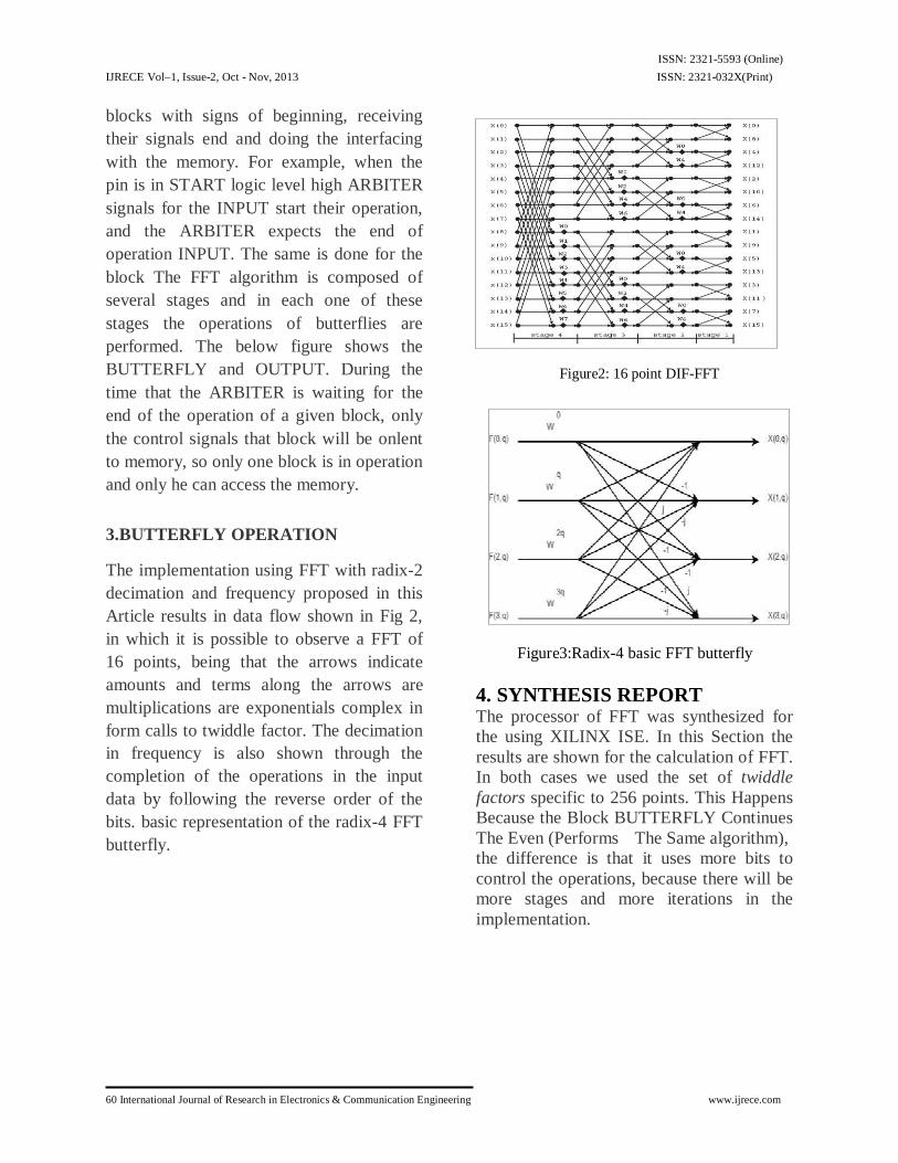
blocks with signs of beginning, receiving their signals end and doing the interfacing with the memory. For example, when the pin is in START logic level high ARBITER signals for the INPUT start their operation, and the ARBITER expects the end of operation INPUT. The same is done for the block The FFT algorithm is composed of several stages and in each one of these stages the operations of butterflies are performed. The below figure shows the BUTTERFLY and OUTPUT. During the time that the ARBITER is waiting for the end of the operation of a given block, only the control signals that block will be onlent to memory, so only one block is in operation and only he can access the memory. 3.BUTTERFLY OPERATION The implementation using FFT with radix-2 decimation and frequency proposed in this Article results in data flow shown in Fig 2, in which it is possible to observe a FFT of 16 points, being that the arrows indicate amounts and terms along the arrows are multiplications are exponentials complex in form calls to twiddle factor. The decimation in frequency is also shown through the completion of the operations in the input data by following the reverse order of the bits. basic representation of the radix-4 FFT butterfly.
Figure2: 16 point DIF-FFT
Figure3:Radix-4 basic FFT butterfly
4. SYNTHESIS REPORT The processor of FFT was synthesized for the using XILINX ISE. In this Section the results are shown for the calculation of FFT. In both cases we used the set of twiddle factors specific to 256 points. This Happens Because the Block BUTTERFLY Continues The Even (Performs The Same algorithm), the difference is that it uses more bits to control the operations, because there will be more stages and more iterations in the implementation.

ISSN: 2321-5593 (Online) IJRECE Vol–1, Issue-2, Oct - Nov, 2013 ISSN: 2321-032X(Print)
www.ijrece.com International Journal of Research in Electronics & Communication Engineering 61
Simulation results:The RTL view of the butterfly structure obtained after the simulation of the 64-point FFT block, Decimation in time domain is shown next and also the internal architecture of the butterfly block is shown.
Fig 3.1: RTL View Of A Butterfly Component Used In 32-Point FFT
Fig 3.2: Internal Architecture of The Butterfly Component
Fig 3.3: Simulation result of 64 FFT
Fig 3.4: Simulation result of 64 FFT
Fig 3.5: Synthesis report
Fig 3.6: Timing Report Of 64FFT
6.CONCLUSION This Article presented the implementation, the results of synthesis and details regarding the internal operations of a processor of FFT.This Project proposes a novel radix-2 FFT processor

ISSN: 2321-5593 (Online) IJRECE Vol–1, Issue-2, Oct - Nov, 2013 ISSN: 2321-032X(Print)
62 International Journal of Research in Electronics & Communication Engineering www.ijrece.com
based on FPGA using Verilog HDL as hardware description language and XILINX design and synthesis tool.The dedicated parallel-pipelined FFT processor architecture can process input data at high speed, and the whole system performance can be greatly improved due to adopting a novel simple address mapping scheme. Improvements in this implementation are done as to reduce the execution time and to achieve high through output for this we have proposed the radix-4 FFT algorithm with DIT. REFERENCES
1. Alan V. Oppenheim, Ronald W. Schafer and John R. Buck, Discrete-Time Signal Processing, Prentice Hal, second edition, 1999.
2. Mandeep Singh Balwinder Singh Pawan Verma, Harpreet Kaur, "VHDL implementation of FFT/IFFT blocks is OFDM", International Conference on Advances in Recent Technologies in Communication and Computing, 2009.
3. James W. Cooley and John W. Tukey, "An algorithm for the machine calculation of complex fourier series," Math Comput., pp. 297 - 301, 1965.
4. Volnei A. Pedroni, Circuit Design with VDHL, MIT Press, ISBN 0- 262-16224-5, 2004.
5. T. Starr, M. Sorbara, J. M. Cioffi and P. J. Silveramn, DSL Advances, Prentice Hall, 2003.
6. Rd. J. ; Ordaz-Moreno A. ; Vite-Frias , J. A. ; Romero-Troncoso , "VHDL core is 1024-point radix-4 fft computation", International Conference on Reconfigurable Computing and FPGAs 2005, ReConFig 2005, pp. 4 - 24, 9 2005.
7. Alvarez-Marquina E. Martinez of Icaya C. Gonzalez- Consejero, V.Rodellar and P. Gonzalez-Vilda , "The portable hardware
design of the FFT Algorithm", Latin American Applied Research, 2007