Fp7 - LEADER Slide 1 ALFRED C&S rods mechanical design C&S_Rods_20121120.ppt Task 3.3 - Primary...
18
Fp7 - LEADER Slide 1 ALFRED C&S rods mechanical design C&S_Rods_20121120.ppt Task 3.3 - Primary system conceptual design of ALFRED Control rods & Safety rods (mech. Design) The LEADER project • ALFRED core layout • Basic concepts • C/R design • S/R concept • Status TOC F. Manni (S.R.S.) D. Vitale Di Maio (S.R.S.) LEADER Technical Meeting November 20 - 23, 2012 Karlsruhe Institut of Technology
-
Upload
amberlynn-golden -
Category
Documents
-
view
217 -
download
0
Transcript of Fp7 - LEADER Slide 1 ALFRED C&S rods mechanical design C&S_Rods_20121120.ppt Task 3.3 - Primary...

Fp7 - LEADER
Slide 1
ALFRED C&S rods mechanical design
C&S_Rods_20121120.ppt
Task 3.3 - Primary system conceptual design of ALFRED
Control rods & Safety rods
(mech. Design)
The LEADER project
• ALFRED core layout• Basic concepts• C/R design• S/R concept• Status
TOC
F. Manni (S.R.S.)D. Vitale Di Maio (S.R.S.)
LEADER Technical MeetingNovember 20 - 23, 2012Karlsruhe Institut of Technology

Fp7 - LEADER
Slide 2
ALFRED C&S rods mechanical design
C&S_Rods_20121120.ppt
171 Fuel Assembly
12 Control Rods
4 Safety Rods
108 Dummy Element
ALFRED Core Layout
171
5
Ø 158

Fp7 - LEADER
Slide 3
ALFRED C&S rods mechanical design
C&S_Rods_20121120.ppt
600
Fully extracted
Fully inserted
680
Lead free level (in operation)
373
0
Basic Concepts
Fully extracted
Fully inserted
Diagrid top plane
Control Rod Safety Rod
Core middle plane 40
40
120
120
840
Scram: buoyancyTuning: stepper motor
Scram: gravity + booster
F/A

Fp7 - LEADER
Slide 4
ALFRED C&S rods mechanical design
C&S_Rods_20121120.ppt
Lead Free Level (during operation)
CoreActive zone
C/R S/R
Diagrid
F/ADra
g
Bal
last
Wei
ght
Buo
yan
cy
±20%
Ref
uel
ing
Op
erat
ion
Pre
load
ed
Spr
ing
counteracting buoyancy effects..
±20%
Ballast
Preloaded Springs
Top GridBasic Concepts

Fp7 - LEADER
Slide 5
ALFRED C&S rods mechanical design
C&S_Rods_20121120.ppt
Control Rod design
• Both Control and Scram purposes• Control: absorber pin bundle actuated by stepper motor driven worm gear• Scram: buoyancy driven (upward insertion)• Only electrical connections required
features:
notes:
•The very large gas plenum implies a big buoyancy force and the need for additional ballast which does not fit in the "standard" ballast housing (room found anyway on the top)• Spring press re-designed in order to host worm gear (for actuation) and additional ballast (unification of F/A spring presses required)

Fp7 - LEADER
Slide 6
ALFRED C&S rods mechanical design
C&S_Rods_20121120.ppt
Gas plenum
Reflector
Absorber
C/R design
Lower half
Reflector
Float
Spike
Absorber pin bundle

Fp7 - LEADER
Slide 7
ALFRED C&S rods mechanical design
C&S_Rods_20121120.ppt
Absorber
680
700
275
0
Reflector
Gas plenum(very large!)
134
0
Reflector30
166
158
33
R14,9
6
C/R design
Absorber Bundle layout
33
33
31
166158
1
(from MYRRAH to ALFRED)
Increased peripheral gap

Fp7 - LEADER
Slide 8
ALFRED C&S rods mechanical design
C&S_Rods_20121120.ppt
nut
solenoid
worm
Control ScramC/R design
Stepper Motor
Float
Actuation

Fp7 - LEADER
Slide 9
ALFRED C&S rods mechanical design
C&S_Rods_20121120.ppt
Ballast
Standard(282 kg)
Additional(83 kg)
C/R: 623 kg
C/R design Due to the very large gas plenum additional ballast is needed to counteract buoyancy
Total mass365 kg

Fp7 - LEADER
Slide 10
ALFRED C&S rods mechanical design
C&S_Rods_20121120.ppt
C/R design
Spring PressTop Grid
Bellevillewashers
Stepper Motor

Fp7 - LEADER
Slide 11
ALFRED C&S rods mechanical design
C&S_Rods_20121120.ppt
Preliminary evaluation of the insertion transient
0,0
0,5
1,0
1,5
2,0
2,5
3,0
3,5
4,0
4,5
5,0
0,000 0,200 0,400 0,600 0,800 1,000 1,200
Acce
lera
tion
[m |
s2 ]
Time [ s ]
Acceleration vs Time
0,00
0,10
0,20
0,30
0,40
0,50
0,60
0,70
0,80
0,000 0,200 0,400 0,600 0,800 1,000 1,200
Spac
e [m
]
Time [s]
Space vs Time
•Lead flow and stopping time impacts on the insertion time are not considered in the preliminary evaluation. •A preliminary insertion time of about 0.85 s has been estimated; considering the negative acceleration for the arrest, the insertion time is longer but should be shorter than 1 s.
C/R design

Fp7 - LEADER
Slide 12
ALFRED C&S rods mechanical design
C&S_Rods_20121120.ppt
Safety Rod concept
• Just scram, not regulation• Scram: gravity driven (downward insertion)• pneumatic booster system needed to speed up insertion• Electrical and Pneumatic connections (Hi and Lo pressure lines) required
features:
notes:
• Very small gas plenum (reduced buoyancy problems)• Structural design and interfaces similar to C/R and F/A

Fp7 - LEADER
Slide 13
ALFRED C&S rods mechanical design
C&S_Rods_20121120.ppt
Absorber
6084
0
1080
Reflector
6060 Reflector
S/R Concept
Very small Gas plenum (not necessary)
Reduced buoyancy
Provisional Layout!

Fp7 - LEADER
Slide 14
ALFRED C&S rods mechanical design
C&S_Rods_20121120.ppt
A1 A2<< >
A1' A2
D
d
F1 < F2 (P1 • A1 < P2 • A1)
F1 >> F2 (P1 • A1 >> P2 • A1)
P1
P2F1
F2
F1
F2
Low pressure chamber
High pressure chamber
Metering pin
Thrust piston
Thrust column
Housing
Orifice
Booster
Adaptation of a proven concept used for automotive safety tests (HyGe sled)
Fp7 - LEADER
Slide 15
ALFRED C&S rods mechanical design
C&S_Rods_20121120.ppt
P1P2
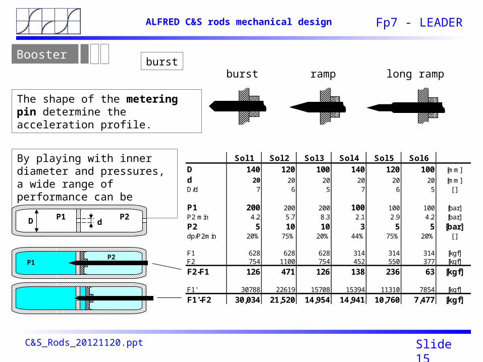
Sol 1 Sol 2 Sol 3 Sol 4 Sol 5 Sol 6D 140 120 100 140 120 100 [mm]
d 20 20 20 20 20 20 [mm]D/d 7 6 5 7 6 5 [ ]
P1 200 200 200 100 100 100 [bar]P2 min 4.2 5.7 8.3 2.1 2.9 4.2 [bar]
P2 5 10 10 3 5 5 [bar]dp/P2min 20% 75% 20% 44% 75% 20% [ ]
F1 628 628 628 314 314 314 [kgf]F2 754 1100 754 452 550 377 [kgf]
F2-F1 126 471 126 138 236 63 [kgf]
F1' 30788 22619 15708 15394 11310 7854 [kgf]
F1'-F2 30,034 21,520 14,954 14,941 10,760 7,477 [kgf]
By playing with inner diameter and pressures, a wide range of performance can be attained.
D dP1 P2
The shape of the metering pin determine the acceleration profile.
burstburst ramp long ramp
Booster

Fp7 - LEADER
Slide 16
ALFRED C&S rods mechanical design
C&S_Rods_20121120.ppt
P1P2
B C
D
A
Active mode:
Solenoid "A", valves "A" and "B" (both normally open) are electrically actuated.De-energizing any (or all) of them will cause depressurization (i.e. "shot" initiation)
Passive mode:
•Loss of electrical supply see above•Low pressure line break see above•High pressure line break causes the mechanical actuation of the Valve "C"
low chamber depressurization is the basic event (but not the only one) which can trigger the device
•The system does not relay on the efficiency of the gas reservoirs or of the feeding lines.•due to the small diameter of the high pressure line, in case of rupture, a significant depressurization of the high pressure chamber occurs after a very long time, therefore enough boosting force is available for scram (caused by automatic actuation of valve "C")
Low pressure line
High pressure line
Booster

Fp7 - LEADER
Slide 17
ALFRED C&S rods mechanical design
C&S_Rods_20121120.ppt
www.hyge.com
Booster

Fp7 - LEADER
Slide 18
ALFRED C&S rods mechanical design
C&S_Rods_20121120.ppt
Status
• C/R mechanical design reports (some amendments needed)• S/R concept
• Unification of F/A, C/R and S/R interfaces • C/R drawings• S/R mechanical design & drawings
done
to do
• 1 month completion time