FP14K & FP14KA - Tuxedo · PDF fileFP14K & FP14KA 14,000 lb Capacity ... Power pack 2hp...
16
FP14K & FP14KA 14,000 lb Capacity Four Post Lifts Installation and Operation Manual REV A-090413
-
Upload
trannguyet -
Category
Documents
-
view
218 -
download
3
Transcript of FP14K & FP14KA - Tuxedo · PDF fileFP14K & FP14KA 14,000 lb Capacity ... Power pack 2hp...

FP14K & FP14KA
14,000 lb CapacityFour Post Lifts
Installation and Operation Manual
REV A-090413

14,000 LB.
FOUR POST LIFTS
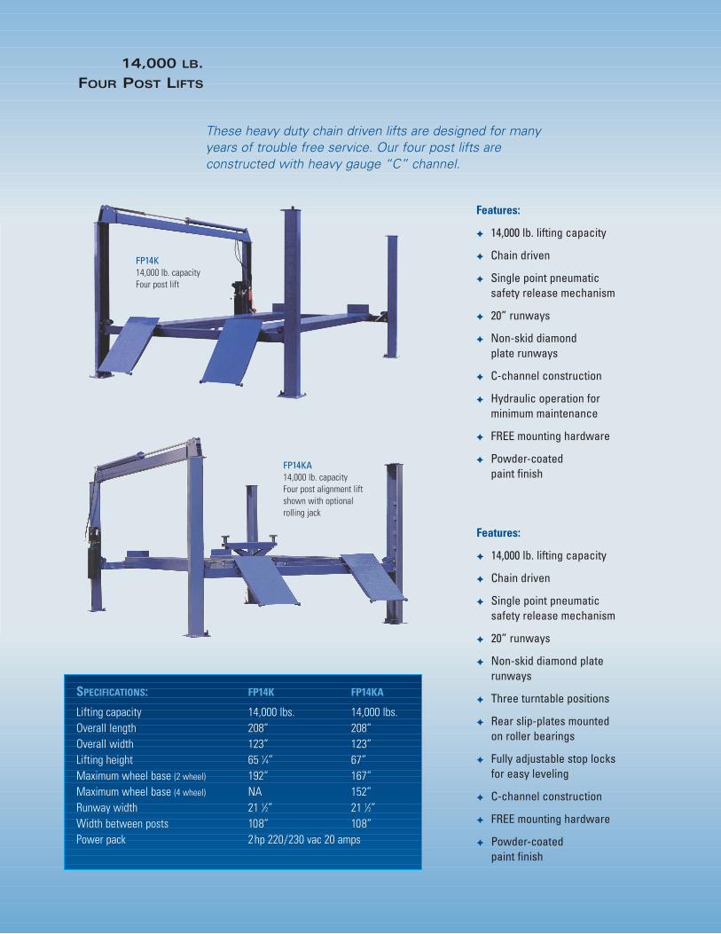
These heavy duty chain driven lifts are designed for manyyears of trouble free service. Our four post lifts are constructed with heavy gauge “C” channel.
Features:
✦ 14,000 lb. lifting capacity
✦ Chain driven
✦ Single point pneumatic safety release mechanism
✦ 20” runways
✦ Non-skid diamond plate runways
✦ Three turntable positions
✦ Rear slip-plates mounted on roller bearings
✦ Fully adjustable stop locks for easy leveling
✦ C-channel construction
✦ FREE mounting hardware
✦ Powder-coated paint finish
SPECIFICATIONS: FP14K FP14KA
Lifting capacity 14,000 lbs. 14,000 lbs.Overall length 208” 208”Overall width 123” 123”Lifting height 65 1⁄4” 67”Maximum wheel base (2 wheel) 192” 167”Maximum wheel base (4 wheel) NA 152”Runway width 21 1⁄2” 21 1⁄2”Width between posts 108” 108”Power pack 2hp 220/230 vac 20 amps
Features:
✦ 14,000 lb. lifting capacity
✦ Chain driven
✦ Single point pneumatic safety release mechanism
✦ 20” runways
✦ Non-skid diamond plate runways
✦ C-channel construction
✦ Hydraulic operation for minimum maintenance
✦ FREE mounting hardware
✦ Powder-coated paint finish
FP14K14,000 lb. capacityFour post lift
FP14KA14,000 lb. capacityFour post alignment liftshown with optionalrolling jack
1905 N Main St Suite C, Cleburne, TX 76033 Ph 817-558-9337 Fax 817-558-9740
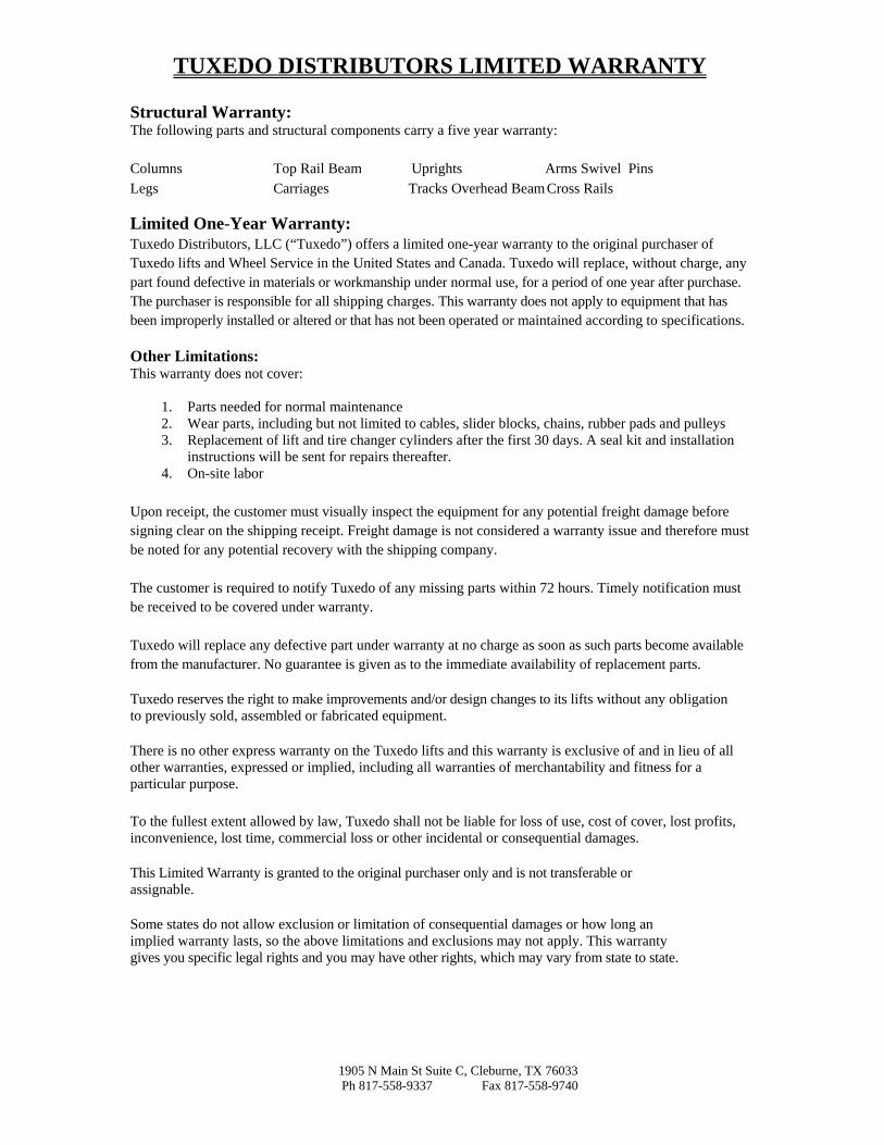
TUXEDO DISTRIBUTORS LIMITED WARRANTY
Structural Warranty: The following parts and structural components carry a five year warranty:
Columns Top Rail Beam Uprights Arms Swivel Pins Legs Carriages Tracks Overhead Beam Cross Rails
Limited One-Year Warranty: Tuxedo Distributors, LLC (“Tuxedo”) offers a limited one-year warranty to the original purchaser of Tuxedo lifts and Wheel Service in the United States and Canada. Tuxedo will replace, without charge, any part found defective in materials or workmanship under normal use, for a period of one year after purchase. The purchaser is responsible for all shipping charges. This warranty does not apply to equipment that has been improperly installed or altered or that has not been operated or maintained according to specifications.
Other Limitations: This warranty does not cover:
1. Parts needed for normal maintenance2. Wear parts, including but not limited to cables, slider blocks, chains, rubber pads and pulleys3. Replacement of lift and tire changer cylinders after the first 30 days. A seal kit and installation
instructions will be sent for repairs thereafter.4. On-site labor
Upon receipt, the customer must visually inspect the equipment for any potential freight damage before signing clear on the shipping receipt. Freight damage is not considered a warranty issue and therefore must be noted for any potential recovery with the shipping company.
The customer is required to notify Tuxedo of any missing parts within 72 hours. Timely notification must be received to be covered under warranty.
Tuxedo will replace any defective part under warranty at no charge as soon as such parts become available from the manufacturer. No guarantee is given as to the immediate availability of replacement parts.
Tuxedo reserves the right to make improvements and/or design changes to its lifts without any obligation to previously sold, assembled or fabricated equipment.
There is no other express warranty on the Tuxedo lifts and this warranty is exclusive of and in lieu of all other warranties, expressed or implied, including all warranties of merchantability and fitness for a particular purpose.
To the fullest extent allowed by law, Tuxedo shall not be liable for loss of use, cost of cover, lost profits, inconvenience, lost time, commercial loss or other incidental or consequential damages.
This Limited Warranty is granted to the original purchaser only and is not transferable or assignable.
Some states do not allow exclusion or limitation of consequential damages or how long an implied warranty lasts, so the above limitations and exclusions may not apply. This warranty gives you specific legal rights and you may have other rights, which may vary from state to state.
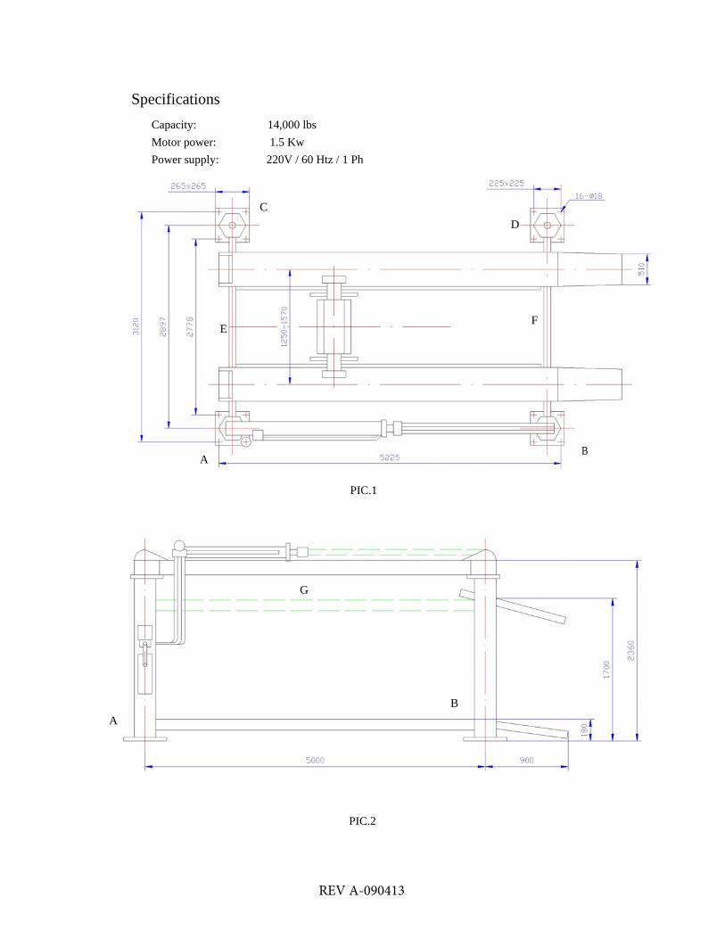
Specifications
Capacity: 14,000 lbs Motor power: 1.5 Kw Power supply: 220V / 60 Htz / 1 Ph
C D
F E
BA
PIC.1
G
B A
PIC.2
REV A-090413

Step1
1. Select a right place for the new lift installation.
PIC.3
2. This lift must be installed on a solid level concrete floor with no more than 0.15 degree ofslope. Or, the four points under the posts should be in level within 10mm.
3. The thickness of the concrete should be at least 4”. The intensity of the concrete should be3,000 PSI.
4. Draw a chalk line layout.
REV A-090413

Step2
1. Locate the main pump column A and main column B on their positions. 2. Anchor the main pump column A. If shimming is required, insert the shims as necessary to
plumb the column.3. Locate the other two columns C and D on their positions. 4. Insert the front and rear cross tubes E and F into the columns. Raise them up to
approximately 18" and place on safety locks.5. Connect the balancing chain LH1234 inside the main column A and column C. 6. Connect another balancing chain LH1234 inside the main column B and column C. 7. Raise up the top cylinder beam G, put it on the main columns A and B. Use M12*50 bolts to
fix the beam to the columns.8. Pull out the piston of the main cylinder for 1750mm. Connect the two chains LH1246 to the
cross tubes.9. Check the positions of the unfixed 3 columns. Adjust the gaps between the tube and column.
Then anchor them. Use shims to plumb the columns.10. Put the runways onto the cross tubes. Fix them by bolts. Take care to place the rolling jack
rails toward the middle of the lift.11. Put on all the accessories such as front wheel stops and ramps. 12. Adjust all the chains enough to level the runways.
Step3 1. Put the electro-hydraulic pump onto the main pump column. 2. Connect all the pipes to pump and cylinders. 3. Connect the wires for the pump motor. 4. Connect the air pipe for the safety locks. (Pic.5) 5. Fill up the pump tank with hydraulic oil for 2/3 capacity. 6. Press the start button for first time raise. Check all the bolts, moving parts, etc. 7. Run up and down several times to see if the lift is OK. 8. Adjust the nuts on the chain ends to level the runways again. 9. Adjust the height of the safety bar inside the column to ensure crosstubes lock properly.
REV A-090413

1. Chain LH1246Main column A Main column B 2. Chain Lh1246
3. Chain LH12344. Main Cylinder
Locking
Column
Air cylinder Unlocking
Cross tube
Safety system
PIC. 4
REV A-090413

1. Air cylinder on column B2. Air cylinder on column A3. Air cylinder on column D4. Air cylinder on column C5. Switch6. Air supply7. Air pipe
Column C / D
1. pressure gauge2. Main cylinder3. Inlet oil pipe4. Outlet oil pipe
1 3
5
4 2 6
7 Main column side
1. Chain LH12462. Safety lock3. Balancing chain LH1234
Main column A / B
PIC. 5
REV A-090413
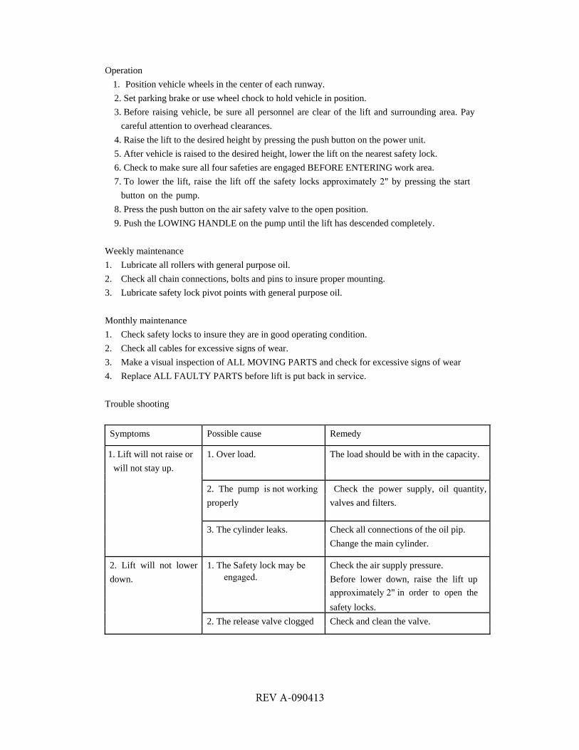
Operation 1. Position vehicle wheels in the center of each runway.2. Set parking brake or use wheel chock to hold vehicle in position.3. Before raising vehicle, be sure all personnel are clear of the lift and surrounding area. Pay
careful attention to overhead clearances.4. Raise the lift to the desired height by pressing the push button on the power unit.5. After vehicle is raised to the desired height, lower the lift on the nearest safety lock.6. Check to make sure all four safeties are engaged BEFORE ENTERING work area.7. To lower the lift, raise the lift off the safety locks approximately 2" by pressing the start
button on the pump.8. Press the push button on the air safety valve to the open position.9. Push the LOWING HANDLE on the pump until the lift has descended completely.
Weekly maintenance 1. Lubricate all rollers with general purpose oil. 2. Check all chain connections, bolts and pins to insure proper mounting. 3. Lubricate safety lock pivot points with general purpose oil.
Monthly maintenance 1. Check safety locks to insure they are in good operating condition. 2. Check all cables for excessive signs of wear. 3. Make a visual inspection of ALL MOVING PARTS and check for excessive signs of wear 4. Replace ALL FAULTY PARTS before lift is put back in service.
Trouble shooting
Symptoms Possible cause Remedy
1. Lift will not raise or 1. Over load. The load should be with in the capacity. will not stay up.
2. The pump is not working Check the power supply, oil quantity,properly valves and filters.
3. The cylinder leaks. Check all connections of the oil pip. Change the main cylinder.
2. Lift will not lower 1. The Safety lock may be engaged.down.
Check the air supply pressure. Before lower down, raise the lift up approximately 2" in order to open the safety locks.
2. The release valve clogged Check and clean the valve.
REV A-090413
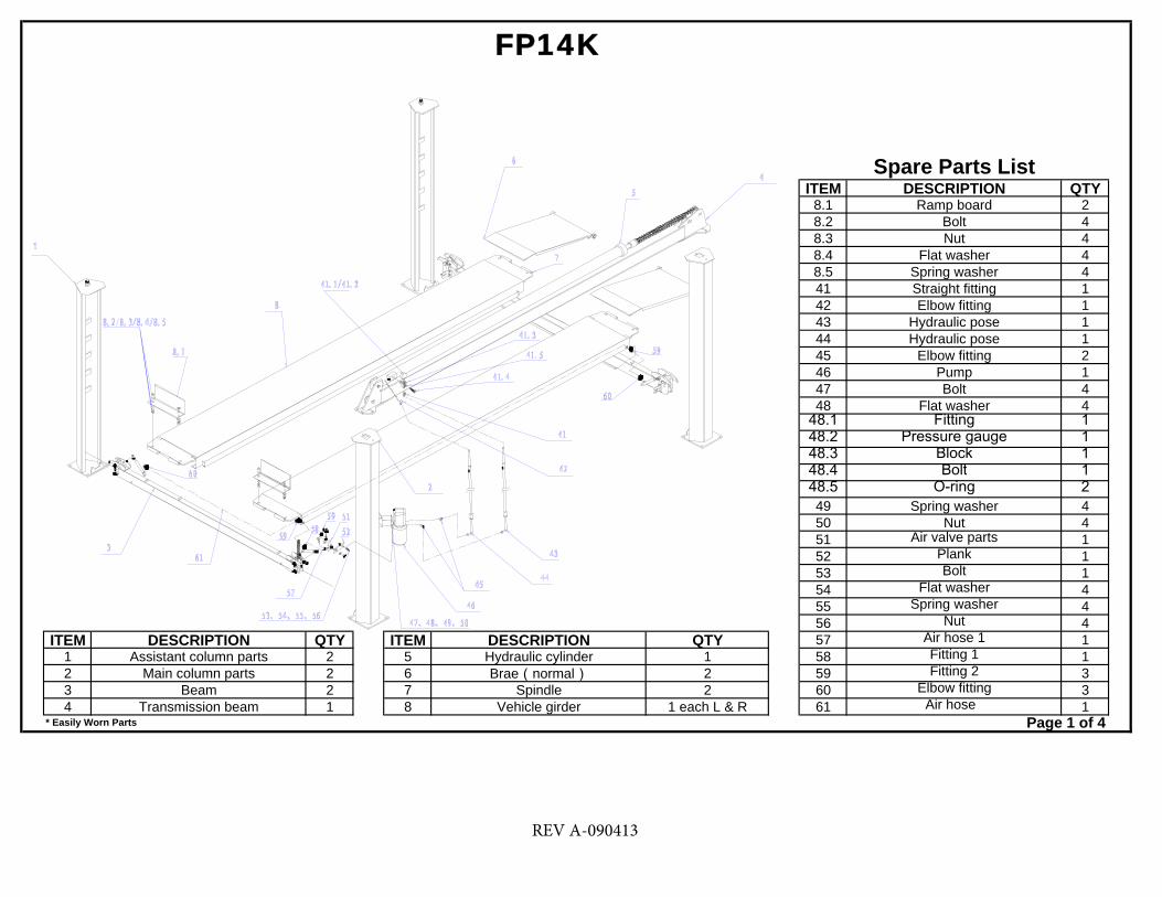
ITEM DESCRIPTION QTY8.1 Ramp board 28.2 Bolt 48.3 Nut 48.4 Flat washer 48.5 Spring washer 441 Straight fitting 142 Elbow fitting 143 Hydraulic pose 144 Hydraulic pose 145 Elbow fitting 246 Pump 147 Bolt 448 Flat washer 4
48.1 Fitting 148.2 Pressure gauge 148.3 Block 148.4 Bolt 148.5 O-ring 249 Spring washer 450 Nut 451 Air valve parts 152 Plank 153 Bolt 154 Flat washer 455 Spring washer 456 Nut 4
ITEM DESCRIPTION QTY ITEM DESCRIPTION QTY 57 Air hose 1 11 Assistant column parts 2 5 Hydraulic cylinder 1 58 Fitting 1 12 Main column parts 2 6 Brae(normal) 2 59 Fitting 2 33 Beam 2 7 Spindle 2 60 Elbow fitting 34 Transmission beam 1 8 Vehicle girder 1 each L & R 61 Air hose 1
FP14K
Spare Parts List
* Easily Worn Parts Page 1 of 4
REV A-090413
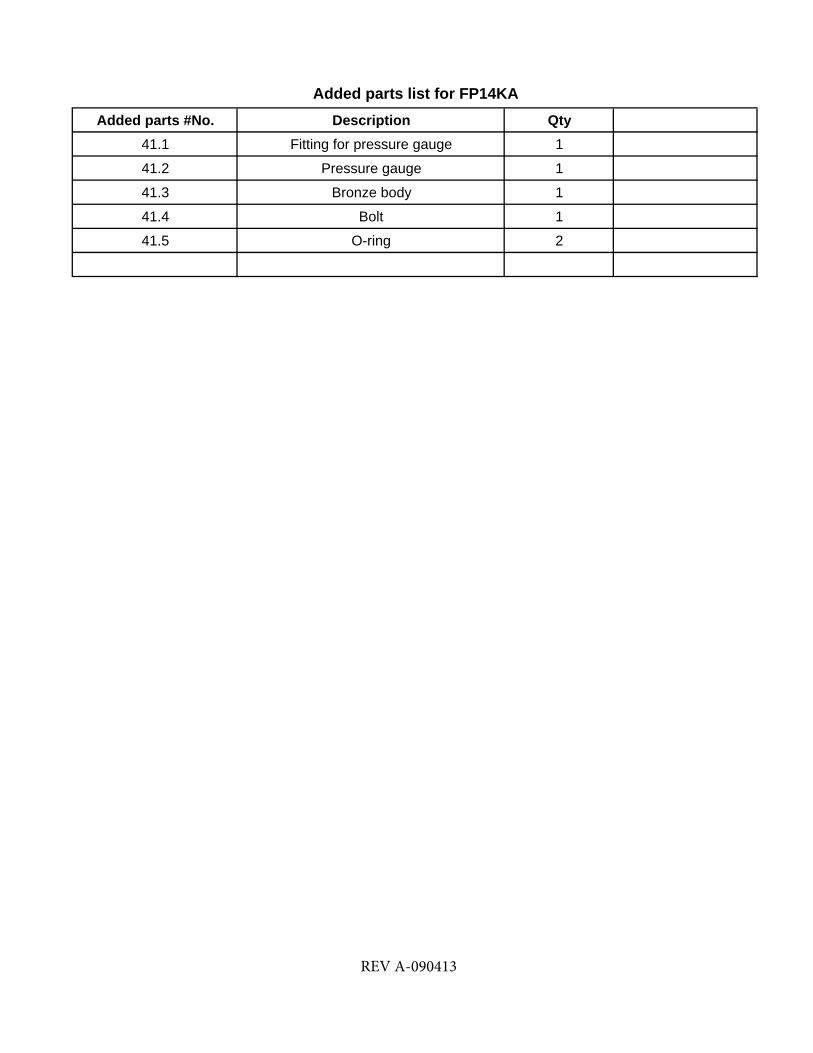
Added parts #No. Description Qty41.1 Fitting for pressure gauge 1
41.2 Pressure gauge 1
41.3 Bronze body 1
41.4 Bolt 1
41.5 O-ring 2
Added parts list for FP14KA
REV A-090413

ITEM QTY4 1
12 112.1 212.2 213 3
13.1 313.2 314 315 616 1
* Easily Worn Parts
Chain seat
Snap ringGalvanized flat washer
Chain wheelMultiple bush
FP14K
Page 2 of 4
Spare Parts ListDESCRIPTION
Transmission beamSpindle
Snap ringFlat washer
Spindle
REV A-090413

ITEM QTY15 617 4
17.1 218 219 220 121 129 4
* Easily Worn Parts
Spare Parts List
FP14K
Chain wheelPage 3 of 4
Chain A(LH1246)Chain B(LH1246)
Flex boltChain
DESCRIPTIONMultiple bush
NutFlat washer
REV A-090413

ITEM QTY22 223 424 825 426 227 828 429 430 431 832 8
32.1 833 834 4
34.1 435 8
35.1 835.2 836 437 8
37.1 837.2 838 4
38.1 838.2 839 240 2
40.1 2
BoltGalvanized nut
Galvanized flat washer
CoverCotter pin
Top bracket(A)Multiple bush
Orientation boardChain wheel
Inner haxangular screwInner haxangular screw
Spring washerGalvanized nut
Spare Parts ListDESCRIPTION
FP14K
* Easily Worn Parts Page 4 of 4
Top bracket(B)Small cylinder
Snap ringBolt
Flat washerOrientation block
Inner haxangular screwSpring washer
Chain seatRight claspLeft clasp
Flat washerWasher
Haxangular nutCross screw
REV A-090413

IMPORTANT
POWER UNIT PRIMING PROCEDURE
THE PROBLEM: Power unit runs fine but will not pump any fluid.
Step 1 – Locate the check valve, the flush plug to the left of the lowering valve.
(See drawing below.)
Step 2 – Using an Allen wrench and shop towel – with shop towel in place to catch
fluid – loosen the check valve plug 2 ½ turns to allow it to leak.
Step 3 – Push the START button for one second, then release for three seconds.
Repeat these steps until unit starts pumping fluid.
Step 4 – Tighten the check valve plug.
YOUR POWER UNIT SHOULD BE PRIMED