
FP-CTR-500 and cFP-CTR-500 Operating …download.ni.com/support/daq/manuals/373323d.pdfFIELDPOINT...
26
FIELDPOINT OPERATING INSTRUCTIONS AND SPECIFICATIONS FP-CTR-500 and cFP-CTR-500 Eight-Channel, 16-Bit Counter Module These operating instructions describe how to install and use the National Instruments FP-CTR-500 and cFP-CTR-500 counter modules (referred to inclusively as the [c]FP-CTR-500). For information about configuring and accessing the [c]FP-CTR-500 over a network, refer to the user manual for the FieldPoint network module you are using. Features The [c]FP-CTR-500 is a FieldPoint counter module with the following features: • Eight 16-bit counters with individual count-input terminals • Four gate-input channels configurable as either gates or digital inputs • Four output channels configurable as either generic digital outputs or associated outputs for the count-input channels • Sinking inputs and sourcing outputs, compatible with 12 and 24 VDC devices • Internal frequency references of 1 kHz and 32 kHz • Internally cascadable counters • Software-enabled 50 kHz or 200 Hz lowpass filter on count-input channels • On/Off LED indicators • 250 V rms CAT II continuous channel-to-ground isolation, verified by 2,300 V rms , 5 s dielectric withstand test • Hot swappable
Transcript of FP-CTR-500 and cFP-CTR-500 Operating …download.ni.com/support/daq/manuals/373323d.pdfFIELDPOINT...
FIELDPOINT OPERATING INSTRUCTIONSAND SPECIFICATIONS
FP-CTR-500 and cFP-CTR-500Eight-Channel, 16-Bit Counter Module
These operating instructions describe how to install and use the National Instruments FP-CTR-500 and cFP-CTR-500 counter modules (referred to inclusively as the [c]FP-CTR-500). For information about configuring and accessing the [c]FP-CTR-500 over a network, refer to the user manual for the FieldPoint network module you are using.
FeaturesThe [c]FP-CTR-500 is a FieldPoint counter module with the following features:
• Eight 16-bit counters with individual count-input terminals
• Four gate-input channels configurable as either gates or digital inputs
• Four output channels configurable as either generic digital outputs or associated outputs for the count-input channels
• Sinking inputs and sourcing outputs, compatible with 12 and 24 VDC devices
• Internal frequency references of 1 kHz and 32 kHz
• Internally cascadable counters
• Software-enabled 50 kHz or 200 Hz lowpass filter on count-input channels
• On/Off LED indicators
• 250 Vrms CAT II continuous channel-to-ground isolation, verified by 2,300 Vrms, 5 s dielectric withstand test
• Hot swappable

FP-CTR-500 and cFP-CTR-500 2 ni.com
Installing the FP-CTR-500The FP-CTR-500 mounts on a FieldPoint terminal base (FP-TB-x), which provides operating power to the module. Installing the FP-CTR-500 onto a powered terminal base does not disrupt the operation of the FieldPoint bank.
To install the FP-CTR-500, refer to Figure 1 and complete the following steps:
1. Slide the terminal base key to either position X, used for any module, or position 8, used for the FP-CTR-500 module.
2. Align the FP-CTR-500 alignment slots with the guide rails on the terminal base.
3. Press firmly to seat the FP-CTR-500 on the terminal base. When the module is firmly seated, the terminal base latch locks it into place.
Figure 1. Installing the FP-CTR-500
Installing the cFP-CTR-500The cFP-CTR-500 mounts on a Compact FieldPoint backplane (cFP-BP-x or cFP-180x), which provides operating power to the module. Installing the cFP-CTR-500 onto a powered backplane does not disrupt the operation of the FieldPoint bank.
1 I/O Module2 Terminal Base
3 Alignment Slot4 Key
5 Latch6 Guide Rails
1
3
2
4
5
6

© National Instruments Corp. 3 FP-CTR-500 and cFP-CTR-500
To install the cFP-CTR-500, refer to Figure 2 and complete the following steps:
1. Align the captive screws on the cFP-CTR-500 with the holes on the backplane. The alignment keys on the cFP-CTR-500 prevent backward insertion.
2. Press firmly to seat the cFP-CTR-500 on the backplane.
3. Using a number 2 Phillips screwdriver with a shank of at least 64 mm (2.5 in.) length, tighten the captive screws to 1.1 N ⋅ m (10 lb ⋅ in.) of torque. The nylon coating on the screws prevents them from loosening.
Figure 2. Installing the cFP-CTR-500
Wiring the [c]FP-CTR-500The FP-TB-x terminal base has connections for each FP-CTR-500 channel and for an external power supply to power the output channels and field devices. The cFP-CB-x connector block
1 cFP I/O Module2 Captive Screws3 cFP Controller
4 Screw Holes5 cFP Backplane
2
2
1
3 54
4
FP-CTR-500 and cFP-CTR-500 4 ni.com
provides the same connections for the cFP-CTR-500. The V and VSUP terminals are all internally connected, as are the C and COM terminals.
Use a 10–30 VDC external power supply for the output channels. The power supply must provide enough current to power all of the loads on the output channels, up to 1 A per channel. Connect the external power supply to multiple V and VSUP terminals and to multiple C and COM terminals as needed to ensure that the maximum current through any terminal is 2 A or less.
Install a 2 A maximum, fast-acting fuse between the external power supply and the V or VSUP terminal on each channel. Install a 1 A maximum, fast-acting fuse suitable for the load at the VOUT terminal. The detailed wiring diagrams in this document show fuses where appropriate.
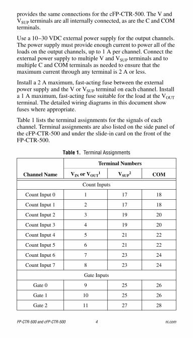
Table 1 lists the terminal assignments for the signals of each channel. Terminal assignments are also listed on the side panel of the cFP-CTR-500 and under the slide-in card on the front of the FP-CTR-500.
Table 1. Terminal Assignments
Channel Name
Terminal Numbers
VIN or VOUT1 VSUP
2 COM
Count Inputs
Count Input 0 1 17 18
Count Input 1 2 17 18
Count Input 2 3 19 20
Count Input 3 4 19 20
Count Input 4 5 21 22
Count Input 5 6 21 22
Count Input 6 7 23 24
Count Input 7 8 23 24
Gate Inputs
Gate 0 9 25 26
Gate 1 10 25 26
Gate 2 11 27 28
© National Instruments Corp. 5 FP-CTR-500 and cFP-CTR-500
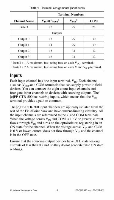
InputsEach input channel has one input terminal, VIN. Each channel also has VSUP and COM terminals that can supply power to field devices. You can connect the eight count-input channels and four gate-input channels to devices with sourcing outputs. The [c]FP-CTR-500 has sinking inputs, which means that the VIN terminal provides a path to common.
The [c]FP-CTR-500 input channels are optically isolated from the rest of the FieldPoint bank and have current-limiting circuitry. All the input channels are referenced to the C and COM terminals. When the voltage across VIN and COM is 10 V or greater, current flows through VIN and turns on the optoisolator, registering in an ON state for the channel. When the voltage across VIN and COM is 6 V or lower, current does not flow through VIN and the channel is in the OFF state.
Ensure that the sourcing-output devices have OFF state leakage currents of less than 0.2 mA so they do not generate false ON state readings.
Gate 3 12 27 28
Outputs
Output 0 13 29 30
Output 1 14 29 30
Output 2 15 31 32
Output 3 16 31 32
1 Install a 1 A maximum, fast-acting fuse on each VOUT terminal.2 Install a 2 A maximum, fast-acting fuse on each V and VSUP terminal.
Table 1. Terminal Assignments (Continued)
Channel Name
Terminal Numbers
VIN or VOUT1 VSUP
2 COM

FP-CTR-500 and cFP-CTR-500 6 ni.com
Figure 3. Wiring a Count-Input or Gate-Input Channel to aSourcing-Output Device
Figure 4. Wiring a Count-Input or Gate-Input Channel to an Externally Powered Sourcing-Output Device
OutputsEach output channel has one output terminal, VOUT. Each channel also has VSUP and COM terminals that you can use to supply power to field devices. You can connect the four output channels to
To next channel [c]FP-CTR-500
V C
+ –
COM
VSUP
VIN Input Circuitry
Sourcing- Output Device
2 A Max User-Supplied
Fuse
10–30 VDC External Power Supply
(Optional)
To next channel
[c]FP-CTR-500
V C
+ –
COM
VSUP
VIN Input Circuitry
Sourcing- Output Device
10–30 VDC External Power Supply
(Optional)
2 A Max User-Supplied
Fuse
© National Instruments Corp. 7 FP-CTR-500 and cFP-CTR-500
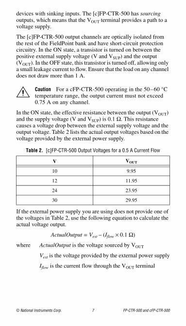
devices with sinking inputs. The [c]FP-CTR-500 has sourcing outputs, which means that the VOUT terminal provides a path to a voltage supply.
The [c]FP-CTR-500 output channels are optically isolated from the rest of the FieldPoint bank and have short-circuit protection circuitry. In the ON state, a transistor is turned on between the positive external supply voltage (V and VSUP) and the output (VOUT). In the OFF state, this transistor is turned off, allowing only a small leakage current to flow. Ensure that the load on any channel does not draw more than 1 A.
Caution For a cFP-CTR-500 operating in the 50–60 °C temperature range, the output current must not exceed 0.75 A on any channel.
In the ON state, the effective resistance between the output (VOUT) and the supply voltage (V and VSUP) is 0.1 Ω. This resistance causes a voltage drop between the external supply voltage and the output voltage. Table 2 lists the actual output voltages based on the voltage provided by the external power supply.
If the external power supply you are using does not provide one of the voltages in Table 2, use the following equation to calculate the actual voltage output.
ActualOutput = Vext – (Iflow × 0.1 Ω)
where ActualOutput is the voltage sourced by VOUT
Vext is the voltage provided by the external power supply
Iflow is the current flow through the VOUT terminal
Table 2. [c]FP-CTR-500 Output Voltages for a 0.5 A Current Flow
V VOUT
10 9.95
12 11.95
24 23.95
30 29.95

FP-CTR-500 and cFP-CTR-500 8 ni.com
Figure 5. Wiring an Output Channel to a Sinking-Input Device
Configuring Count-Input ChannelsChannels 0–7 are count-input channels. In FieldPoint software, you can configure each count-input channel to operate with attributes and commands. In the Channel Configuration dialog box, select attributes for each channel from the Attributes menu and commands from the Commands menu. The following sections describe the different attributes and commands you can select when you are configuring the count-input channels. For more information about using FieldPoint software, refer to the FieldPoint software help file.
Terminal CountTo set the terminal count, enter a value from 0 to 65,535 in the Value field. The default value is 65,535. When the count-input channel exceeds its terminal count, the count resets to 0 and triggers any outputs associated with it. For more information about associating outputs with a count-input channel, refer to the Configuring Output Channels section. The count-input channel also sends a count trigger to the next count-input channel if that channel is set to use the previous channel as the count source.
Channel StatusIn FieldPoint software, the [c]FP-CTR-500 reports one of the following statuses: Successful or Overflow since last read. The default channel status is Successful. If a count-input
Load
To next channel
[c]FP-CTR-500
V C
COM
VOUT
VSUP
Sourcing- Output
Circuitry
+
–
10–30 VDC External Power Supply
2 A Max User-Supplied
Fuse
1 A Max User-Supplied
Fuse
© National Instruments Corp. 9 FP-CTR-500 and cFP-CTR-500
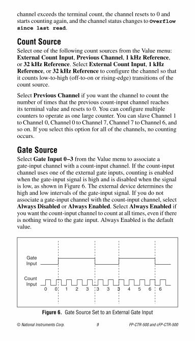
channel exceeds the terminal count, the channel resets to 0 and starts counting again, and the channel status changes to Overflow since last read.
Count SourceSelect one of the following count sources from the Value menu: External Count Input, Previous Channel, 1 kHz Reference, or 32 kHz Reference. Select External Count Input, 1 kHz Reference, or 32 kHz Reference to configure the channel so that it counts low-to-high (off-to-on or rising-edge) transitions of the count source.
Select Previous Channel if you want the channel to count the number of times that the previous count-input channel reaches its terminal value and resets to 0. You can configure multiple counters to operate as one large counter. You can slave Channel 1 to Channel 0, Channel 0 to Channel 7, Channel 7 to Channel 6, and so on. If you select this option for all of the channels, no counting occurs.
Gate SourceSelect Gate Input 0–3 from the Value menu to associate a gate-input channel with a count-input channel. If the count-input channel uses one of the external gate inputs, counting is enabled when the gate-input signal is high and is disabled when the signal is low, as shown in Figure 6. The external device determines the high and low intervals of the gate-input signal. If you do not associate a gate-input channel with the count-input channel, select Always Disabled or Always Enabled. Select Always Enabled if you want the count-input channel to count at all times, even if there is nothing wired to the gate input. Always Enabled is the default value.
Figure 6. Gate Source Set to an External Gate Input
0 0 1 2 3 3 3 3 4 5 6 6
GateInput
CountInput
FP-CTR-500 and cFP-CTR-500 10 ni.com
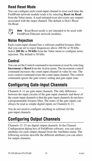
Read Reset ModeYou can configure each count-input channel to reset each time the FieldPoint network module reads it by selecting Reset on Read from the Value menu. A read-initiated reset also resets any outputs associated with the target channel. The default is Don’t Reset On Read.
Note Read Reset mode is not intended to be used with FieldPoint Ethernet network modules.
Noise RejectionEach count-input channel has a software-enabled lowpass filter that you can set to reject frequencies above 200 Hz or 50 kHz. Select 200 Hz or 50 kHz from the Value menu to configure noise rejection. The default is 50 kHz.
ControlYou can set the Control command to increment or reset by selecting Increment or Reset from the Action menu. The increment-control command increases the count-input channel in value by one. The reset-control command resets the count-input channel. The control commands ignore the gate-source setting and gate-input state.
Configuring Gate-Input ChannelsChannels 8–11 are gate-input channels. The only difference between the input circuits of the gate-input channels and those of the count-input channels is that the gate-input channels do not have a programmable lowpass filter. The states of the gate inputs can always be read as simple digital inputs on Channels 8–11.
You do not need to configure anything in software for the gate-input channels.
Configuring Output ChannelsChannels 12–15 are digital output channels. In the Channel Configuration dialog box of FieldPoint software, you can select attributes for each output channel from the Attributes menu. The following sections describe the different attributes you can select for output channels.

© National Instruments Corp. 11 FP-CTR-500 and cFP-CTR-500
Output SourceYou can configure each output channel to operate either as an associated output for one of the eight count-input channels or as a generic digital output. Select Counter Channel 0–7 from the Value menu if you want the digital output channel to operate as an output for a corresponding count-input channel. Select Discrete Data from the Value menu if you want to use this channel as a generic digital output. When you write data to an output channel, you affect the output state only if you configure the Output Source as Discrete Data.
Output ModeFor each output channel, select one of the following output modes from the Value menu: Toggle, Reset Off; Toggle, Reset On; On Pulse; or Off Pulse. The output modes work only if you select Counter Channel 0–7 for the Output Source. The following sections describe the different output modes.
Toggle, Reset OffIn Toggle, Reset Off mode, the output channel starts low and goes high when the terminal count is exceeded. The output channel returns to low the next time the terminal count is exceeded or when you send a reset command to the associated count-input channel. In Figure 7, the terminal count is 4.
Figure 7. Output of a Channel Set to Toggle, Reset Off Mode
0 1 2 3 4 0 1 2 3 4 0 1
Output
CountInput
FP-CTR-500 and cFP-CTR-500 12 ni.com
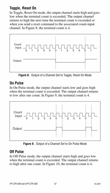
Toggle, Reset OnIn Toggle, Reset On mode, the output channel starts high and goes low when the terminal count is exceeded. The output channel returns to high the next time the terminal count is exceeded or when you send a reset command to the associated count-input channel. In Figure 8, the terminal count is 4.
Figure 8. Output of a Channel Set to Toggle, Reset On Mode
On PulseIn On Pulse mode, the output channel starts low and goes high when the terminal count is exceeded. The output channel returns to low after one count. In Figure 9, the terminal count is 4.
Figure 9. Output of a Channel Set to On Pulse Mode
Off PulseIn Off Pulse mode, the output channel starts high and goes low when the terminal count is exceeded. The output channel returns to high after one count. In Figure 10, the terminal count is 4.
0 1 2 3 4 0 1 2 3 4 0 1
Output
CountInput
0 1 2 3 4 0 1 2 3 4 0 1
Output
CountInput

© National Instruments Corp. 13 FP-CTR-500 and cFP-CTR-500
Figure 10. Output of a Channel Set to Off Pulse Mode
Short-Circuit ProtectionIf the protection circuitry detects a short-circuit condition on an output channel, it disables the output. If the protection circuitry disables an output that would otherwise be in the ON state, the status indicator for that channel remains lit, but the output transistor is turned off.
Detecting a Short-Circuit ConditionTo determine if a channel is in a short-circuit condition, measure the voltage between the VOUT and VSUP terminals. If the voltage is greater than 1 V, the channel is in a short-circuit condition. Correct the problem and reset the circuit.
Resetting a Channel in a Short-Circuit ConditionTo reset a channel in a short-circuit condition, determine the cause of the condition and disconnect the load from the channel. The channel resets automatically when the load is removed.
Alternatively, if completely removing the channel load is not convenient, reset the channel in any of the following ways.
• In FieldPoint software, write a 0 to the channel. The channel resets immediately.
• Disconnect the external power supply from the [c]FP-CTR-500.
• Remove the [c]FP-CTR-500 from the bank.
• Power off the network module connected to the [c]FP-CTR-500.
Normal operation can resume after you correct the short-circuit condition.
0 1 2 3 4 0 1 2 3 4 0 1
Output
CountInput
FP-CTR-500 and cFP-CTR-500 14 ni.com
Overcurrent ProtectionEach output channel on the [c]FP-CTR-500 has circuitry that protects it from current surges resulting from short circuits. Whether the module suffers damage from overcurrent conditions depends on the following factors:
• The amount of current through the channel
• The amount of time the current is above the current limit
• The frequency of the current surges
If the level of current through the output terminal is higher than the guaranteed trip current for the module, the channel trips and goes into an overcurrent state. In an overcurrent state, the channel turns off and the module is not damaged. If the level of current through the output terminal is higher than the minimum possible trip current and lower than the guaranteed trip current, the state of the channel is indeterminate and depends on factors such as the current level, the temperature, and the power supply.
Inrush currents that exist for less than the trip time do not trip the protection circuitry. Refer to the Specifications section for more information about the maximum continuous output current, trip current, and trip time.
Note Because the [c]FP-CTR-500 module includes internal flyback diodes, you do not need to add external diodes when connecting to devices.
Power Supplies and Overcurrent ConditionsIf a short-circuit condition occurs, the current through an output terminal can exceed the current rating for the power supply and the maximum continuous output current for the [c]FP-CTR-500. If the power supply you are using with the [c]FP-CTR-500 cannot supply more than the guaranteed trip current, the module may be damaged if a short-circuit condition occurs.
Application Note: Generating a Continuous Pulse TrainYou can use two [c]FP-CTR-500 count-input channels and one output channel to generate a continuous pulse train with a controllable duty cycle and period. The first count-input channel serves as a clock prescaler and divides the input clock by a fixed

© National Instruments Corp. 15 FP-CTR-500 and cFP-CTR-500
value. This generates a slower clock for the second count-input channel, which serves as the pulse counter. The pulse counter is the output source for the output channel.
Figure 11 shows the components of a continuous pulse train.
Figure 11. Continuous Pulse Train
Step 1. Set Up the Prescaler CounterTo set up the prescaler counter, complete the following steps:
1. If you do not need to scale the frequency of your clock input, you can configure the pulse counter to use the clock input directly instead of the prescaler counter. To set up the pulse counter, skip to Step 2. Set Up the Pulse Counter.
2. Select two count-input channels and one output channel to use. Select count-input channels that are numbered sequentially (for example, Channels 1 and 2, 5 and 6, or 7 and 0). The count-input channel with the lower number is the prescaler counter and the count-input channel with the higher number is the pulse counter.
3. Set the Gate Source attribute of the prescaler counter to Always Enabled, and set Read Reset Mode to Don’t Reset On Read.
4. Set the Count Source of the prescaler counter to the clock on which you want to base your pulse train. This can be the external counter input or one of the [c]FP-CTR-500 internal references.
5. Subtract 1 from the value that you want to divide the input clock by, and set the terminal count of the prescaler counter to the result. For example, a terminal count of 4 divides the input
ClockInput Prescaler
Counter n
PulseCounter
n + 1
InternalConnection
InternalConnection
Output
Pulse Output Terminal

FP-CTR-500 and cFP-CTR-500 16 ni.com
clock by 5. If you use the 1 kHz reference as the prescaler count source, this setting generates a 200 Hz clock for the pulse counter.
To determine the frequency of the prescaler output, use the following formula:
where fpre is the frequency of the prescaler counter output
fsrc is the count input frequency for the prescaler counter
termpre is the terminal count value for the prescaler counter
Step 2. Set Up the Pulse CounterTo set up the pulse counter, complete the following steps:
1. Set the Count Source of the pulse counter (the count-input channel with the higher number) to Previous Channel so that it uses the output from the prescaler counter.
Note If you are not using a prescaler counter, set the Count Source to the clock on which you want to base your pulse train.
2. Set the Read Reset Mode of the pulse counter to Don’t Reset On Read and set the Gate Source to Always Enabled.
3. Subtract 1 from the value that you want to divide the count input by and set the Terminal Count of the pulse counter to the result.
The internal output from the pulse counter triggers the output channel that you selected for the pulse train output.
To determine the frequency of the output from the pulse counter, use the following formula:
where fpulse is the pulse counter output frequency
fpre is the prescaler counter output frequency
termpulse is the terminal count value for the pulse counter
fprefsrc
termpre 1+----------------------------=
fpulsefpre
termpulse 1+--------------------------------=
© National Instruments Corp. 17 FP-CTR-500 and cFP-CTR-500
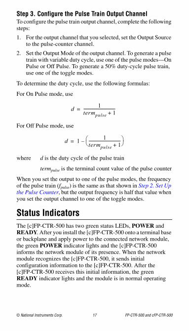
Step 3. Configure the Pulse Train Output ChannelTo configure the pulse train output channel, complete the following steps:
1. For the output channel that you selected, set the Output Source to the pulse-counter channel.
2. Set the Output Mode of the output channel. To generate a pulse train with variable duty cycle, use one of the pulse modes—On Pulse or Off Pulse. To generate a 50% duty-cycle pulse train, use one of the toggle modes.
To determine the duty cycle, use the following formulas:
For On Pulse mode, use
For Off Pulse mode, use
where d is the duty cycle of the pulse train
termpulse is the terminal count value of the pulse counter
When you set the output to one of the pulse modes, the frequency of the pulse train (fpulse) is the same as that shown in Step 2. Set Up the Pulse Counter, but the output frequency is half that value when you set the output channel to one of the toggle modes.
Status IndicatorsThe [c]FP-CTR-500 has two green status LEDs, POWER and READY. After you install the [c]FP-CTR-500 onto a terminal base or backplane and apply power to the connected network module, the green POWER indicator lights and the [c]FP-CTR-500 informs the network module of its presence. When the network module recognizes the [c]FP-CTR-500, it sends initial configuration information to the [c]FP-CTR-500. After the [c]FP-CTR-500 receives this initial information, the green READY indicator lights and the module is in normal operating mode.
d 1termpulse 1+-------------------------------- =
d 1 1termpulse 1+--------------------------------⎝ ⎠⎛ ⎞–=

FP-CTR-500 and cFP-CTR-500 18 ni.com
In addition to the green POWER and READY indicators, each channel has a numbered, green status indicator that lights when the channel is in the ON state.
Upgrading Your FieldPoint FirmwareYou may need to upgrade your FieldPoint firmware when you add new I/O modules to your FieldPoint system. For more information on determining which firmware you need and how to upgrade your firmware, go to ni.com/info and enter fpmatrix.
Isolation and Safety Guidelines
Caution Read the following information before attempting to connect the [c]FP-CTR-500 to any circuits that may contain hazardous voltages.
This section describes the isolation of the [c]FP-CTR-500 and its compliance with international safety standards. The field wiring connections are isolated from the backplane and the inter-module communication bus. The isolation is provided by the module, which has optical and galvanic isolation barriers designed and tested to protect against transient fault voltages of up to 2,300 Vrms.
Follow these guidelines to ensure a safe total system.
• The [c]FP-CTR-500 has a safety isolation barrier between the I/O channels and the inter-module communication bus. There is no isolation between channels unless otherwise noted. If any of the channels on a module are wired at a hazardous potential, make sure that all other devices or circuits connected to that module are properly insulated from human contact.
• Do not share the external supply voltages (the V and C terminals) with other devices (including other FieldPoint devices), unless those devices are isolated from human contact.
• For Compact FieldPoint, you must connect the protective earth (PE) ground terminal on the cFP-BP-x backplane to the system safety ground. The backplane PE ground terminal has the following symbol stamped beside it: . Connect the backplane PE ground terminal to the system safety ground using 14 AWG (1.6 mm) wire with a ring lug. Use the 5/16 in. panhead screw shipped with the backplane to secure the ring lug to the backplane PE ground terminal.

© National Instruments Corp. 19 FP-CTR-500 and cFP-CTR-500
• As with any hazardous voltage wiring, make sure that all wiring and connections meet applicable electrical codes and commonsense practices. Mount terminal bases and backplanes in an area, position, or cabinet that prevents accidental or unauthorized access to wiring that carries hazardous voltages.
• Operate the [c]FP-CTR-500 only at or below Pollution Degree 2. Pollution Degree 2 means that only nonconductive pollution occurs in most cases. Occasionally, however, a temporary conductivity caused by condensation must be expected.
• Refer to the FieldPoint product label for regulatory certification under hazardous location standards. If the FieldPoint product is not certified for operation in hazardous locations, do not operate it in an explosive atmosphere or where there may be flammable gases or fumes.
Safety Guidelines for Hazardous LocationsThe cFP-CTR-500 is suitable for use in Class I, Division 2, Groups A, B, C, D, T4 hazardous locations; Class I, Zone 2, AEx nC IIC T4 and Ex nC IIC T4 hazardous locations; and nonhazardous locations only. Follow these guidelines if you are installing the cFP-CTR-500 in a potentially explosive environment. Not following these guidelines may result in serious injury or death.
Caution Do not disconnect I/O-side wires or connectors unless power has been switched off or the area is known to be nonhazardous.
Caution Do not remove modules unless power has been switched off or the area is known to be nonhazardous.
Caution Substitution of components may impair suitability for Class I, Division 2.
Caution For Zone 2 applications, install the Compact FieldPoint system in an enclosure rated to at least IP 54 as defined by IEC 60529 and EN 60529.
Caution For Zone 2 applications, install a protection device across the external power supply and the COM terminal. The device must prevent the external power supply voltage from exceeding 42 V if there is a transient overvoltage condition.

FP-CTR-500 and cFP-CTR-500 20 ni.com
Special Conditions for Hazardous Locations Use in EuropeThis equipment has been evaluated as EEx nC IIC T4 equipment under DEMKO Certificate No. 03 ATEX 0251502X. Each module is marked II 3G and is suitable for use in Zone 2 hazardous locations.
SpecificationsThe following specifications are typical for the full operating temperature range of the module unless otherwise noted.
Input CharacteristicsNumber of channels.......................... 12 (8 count, 4 gate)
Input type .......................................... 10–30 VDC sinking, compatible with most 12 and 24 VDC devices
Maximum input voltage.................... 30 VDC
Input threshold levelON state...................................... ≥10 VOFF state .................................... ≤6 V
Input current limiting........................ 5 mA maximum
Input bandwidthCount inputs ............................... 50 kHz; 200 Hz with
software-enabled lowpass filter
Gate inputs.................................. 50 kHz
Maximum off-state leakagecurrent for external devices............... 0.2 mA
Output CharacteristicsNumber of channels.......................... 4
Output type ....................................... 10–30 VDC sourcing, compatible with most 12 or 24 VDC devices
Supply voltage .................................. 10–30 VDC, user-provided
Maximum output current per channel........................................ 1 A (0.75 A for
cFP-CTR-500 operating at 50–60 °C)
Output impedance............................. 0.1 Ω
© National Instruments Corp. 21 FP-CTR-500 and cFP-CTR-500
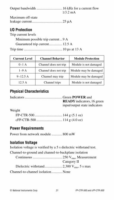
Output bandwidth ............................. 16 kHz for a current flow ≥3.2 mA
Maximum off-stateleakage current.................................. 25 μA
I/O ProtectionTrip current levels
Minimum possible trip current ... 9 AGuaranteed trip current............... 12.5 A
Trip time ........................................... 10 μs at 13 A
Physical CharacteristicsIndicators ..........................................Green POWER and
READY indicators, 16 green input/output state indicators
WeightFP-CTR-500 ............................... 144 g (5.1 oz)cFP-CTR-500 ............................. 114 g (4.0 oz)
Power RequirementsPower from network module ............ 800 mW
Isolation VoltageIsolation voltage is verified by a 5 s dielectric withstand test.
Channel-to-ground and channel-to-backplane isolationContinuous ................................. 250 Vrms, Measurement
Category IIDielectric withstand.................... 2,300 Vrms, 5 s max
Channel-to-channel isolation ............None
Current Level Channel Behavior Module Protection
0–1 A Channel does not trip Module is not damaged
1–9 A Channel does not trip Module may be damaged
9–12.5 A Channel may trip Module may be damaged
12.5 A Channel trips Module is not damaged
FP-CTR-500 and cFP-CTR-500 22 ni.com
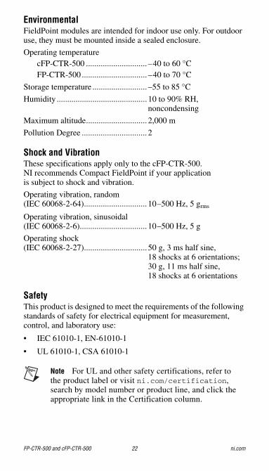
EnvironmentalFieldPoint modules are intended for indoor use only. For outdoor use, they must be mounted inside a sealed enclosure.
Operating temperaturecFP-CTR-500 ............................. –40 to 60 °CFP-CTR-500 ............................... –40 to 70 °C
Storage temperature .......................... –55 to 85 °C
Humidity ........................................... 10 to 90% RH, noncondensing
Maximum altitude............................. 2,000 m
Pollution Degree ............................... 2
Shock and VibrationThese specifications apply only to the cFP-CTR-500. NI recommends Compact FieldPoint if your application is subject to shock and vibration.
Operating vibration, random (IEC 60068-2-64).............................. 10–500 Hz, 5 grms
Operating vibration, sinusoidal (IEC 60068-2-6)................................ 10–500 Hz, 5 g
Operating shock (IEC 60068-2-27).............................. 50 g, 3 ms half sine,
18 shocks at 6 orientations;30 g, 11 ms half sine, 18 shocks at 6 orientations
SafetyThis product is designed to meet the requirements of the following standards of safety for electrical equipment for measurement, control, and laboratory use:
• IEC 61010-1, EN-61010-1
• UL 61010-1, CSA 61010-1
Note For UL and other safety certifications, refer to the product label or visit ni.com/certification, search by model number or product line, and click the appropriate link in the Certification column.

© National Instruments Corp. 23 FP-CTR-500 and cFP-CTR-500
Electromagnetic CompatibilityThis product is designed to meet the requirements of the following standards of EMC for electrical equipment for measurement, control, and laboratory use:
• EN 61326 EMC requirements; Industrial Immunity
• EN 55011 Emissions; Group 1, Class A
• CE, C-Tick, ICES, and FCC Part 15 Emissions; Class A
CE ComplianceThis product meets the essential requirements of applicable European Directives, as amended for CE marking, as follows:
• 73/23/EEC; Low-Voltage Directive (safety)
• 89/336/EEC; Electromagnetic Compatibility Directive (EMC)
Note Refer to the Declaration of Conformity (DoC) for this product for any additional regulatory compliance information. To obtain the DoC for this product, visit ni.com/certification, search by model number or product line, and click the appropriate link in the Certification column.
Waste Electrical and Electronic Equipment (WEEE)
EU Customers At the end of their life cycle, all products must be sent to a WEEE recycling center. For more information about WEEE recycling centers and National Instruments WEEE initiatives, visit ni.com/environment/weee.htm.
FP-CTR-500 and cFP-CTR-500 24 ni.com
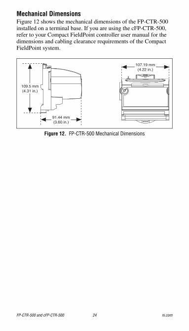
Mechanical DimensionsFigure 12 shows the mechanical dimensions of the FP-CTR-500 installed on a terminal base. If you are using the cFP-CTR-500, refer to your Compact FieldPoint controller user manual for the dimensions and cabling clearance requirements of the Compact FieldPoint system.
Figure 12. FP-CTR-500 Mechanical Dimensions
109.5 mm(4.31 in.)
91.44 mm(3.60 in.)
107.19 mm(4.22 in.)

© National Instruments Corp. 25 FP-CTR-500 and cFP-CTR-500
Where to Go for SupportFor more information about setting up the FieldPoint system, refer to these National Instruments documents:
• FieldPoint network module user manual
• Other FieldPoint I/O module operating instructions
• FieldPoint terminal base and connector block operating instructions
Go to ni.com/support for the most current manuals, examples, and troubleshooting information.
National Instruments corporate headquarters is located at 11500 North Mopac Expressway, Austin, Texas, 78759-3504. National Instruments also has offices located around the world to help address your support needs. For telephone support in the United States, create your service request at ni.com/support and follow the calling instructions or dial 512 795 8248. For telephone support outside the United States, contact your local branch office:
Australia 1800 300 800, Austria 43 662 457990-0, Belgium 32 (0) 2 757 0020, Brazil 55 11 3262 3599, Canada 800 433 3488, China 86 21 5050 9800, Czech Republic 420 224 235 774, Denmark 45 45 76 26 00, Finland 385 (0) 9 725 72511, France 33 (0) 1 48 14 24 24, Germany 49 89 7413130, India 91 80 41190000, Israel 972 3 6393737, Italy 39 02 413091, Japan 81 3 5472 2970, Korea 82 02 3451 3400, Lebanon 961 (0) 1 33 28 28, Malaysia 1800 887710, Mexico 01 800 010 0793, Netherlands 31 (0) 348 433 466, New Zealand 0800 553 322, Norway 47 (0) 66 90 76 60, Poland 48 22 3390150, Portugal 351 210 311 210, Russia 7 495 783 6851, Singapore 1800 226 5886, Slovenia 386 3 425 42 00, South Africa 27 0 11 805 8197, Spain 34 91 640 0085, Sweden 46 (0) 8 587 895 00, Switzerland 41 56 2005151, Taiwan 886 02 2377 2222, Thailand 662 278 6777, Turkey 90 212 279 3031, United Kingdom 44 (0) 1635 523545

© 2002–2007 National Instruments Corp. All rights reserved.
373323D-01 May07
National Instruments, NI, ni.com, and LabVIEW are trademarks of National Instruments Corporation. Refer to the Terms of Use section on ni.com/legal for more information about National Instruments trademarks. Other product and company names mentioned herein are trademarks or trade names of their respective companies. For patents covering National Instruments products, refer to the appropriate location: Help»Patents in your software, the patents.txt file on your CD, or ni.com/patents.