Foundation (2)
69
Choice of the Type of Foundation The choice of the appropriate type of foundation is governed by some important factors such as 1. The nature of the structure 2. The loads exerted by the structure 3. The subsoil characteristics 4. The allotted cost of foundations Therefore to decide about the type of foundation, subsoil exploration must be carried out. Then the soil characteristics within the affected zone below the building should be carefully evaluated. The allowable bearing capacity of the affected soil strata should then be estimated. After this study, one could then decide whether shallow foundations or deep foundations should be used. Shallow foundations, such as footings and rafts, cost less and easier to execute. They could be used if the following two conditions are fulfilled; 1. The superimposed stress (p) caused by the building lies within the allowable bearing capacity diagram of different soil strata as shown in Fig.1. This condition is fulfilled when , in Fig.1, is smaller than and smaller than and smaller than and smaller than and so on.
-
Upload
topukuet -
Category
Engineering
-
view
58 -
download
1
Transcript of Foundation (2)

Choice of the Type of Foundation
The choice of the appropriate type of foundation is governed by some
important factors such as
1. The nature of the structure
2. The loads exerted by the structure
3. The subsoil characteristics
4. The allotted cost of foundations
Therefore to decide about the type of foundation, subsoil exploration must be
carried out. Then the soil characteristics within the affected zone below the
building should be carefully evaluated. The allowable bearing capacity of the
affected soil strata should then be estimated.
After this study, one could then decide whether shallow foundations or deep
foundations should be used.
Shallow foundations, such as footings and rafts, cost less and easier to
execute. They could be used if the following two conditions are fulfilled;
1. The superimposed stress (p) caused by the building lies within
the allowable bearing capacity diagram of different soil strata as
shown in Fig.1.
This condition is fulfilled when , in Fig.1, is smaller than and smaller
than and smaller than and smaller than and so on.

2. The building could withstand the expected settlement estimated for
that type of foundation
If one or both of these two conditions cannot be fulfilled the use of deep
foundations should be considered.
Deep foundations are used when top layers of the soil are soft and there exists
a good bearing stratum at a reasonable depth. Soil strata lying beneath the
bearing stratum should be of ample strength to resist the superimposed
stresses (p) due to the loads transmitted to the bearing stratum, as shown in
Fig.2.

Deep foundations are usually piles or piers which transmits the load of the
building to the good bearing stratum. They usually cost more and require well
trained engineers to execute.
If the explored soil layers are soft for considerable depth and no bearing
stratum is found at a reasonable depth, floating foundations could be used.
To build a floating foundation, a mass of soil, approximately equal to the weight of the proposed building, is to be removed and replaced by the building. In this case, the
bearing stress under the building will be equal to the weight of the removed earth (γD)

which is less than
(qa = γD +2C)
and p will be equal to zero. This means that the bearing capacity under the
building is less than ( qa ) and the expected settlement equals theoretically to
zero.
Finally, the engineer should prepare an estimate of the cost of the most
promising type of foundation which represents the most acceptable
compromise between performance and cost.
Shallow Foundations
Shallow foundations are those executed near the ground surface or at shallow
depths. As mentioned before in the previous chapter, shallow foundations are
used when subsoil exploration proves that all soil strata affected by the building
could resist the superimposed stresses (p) without causing excessive
settlements.
Shallow foundations are either footings or rafts.
Footings
Footing foundation is one of the oldest and most popular type of shallow
foundations. A footing is an enlargement of the base of a column or wall for the
purpose of distributing the load on the supporting soil at a pressure suiting its
properties.
Types of Footings
There are different types of footings to suit the nature of the structure. Footings
could be classified into three main classes
Wall or Strip footing
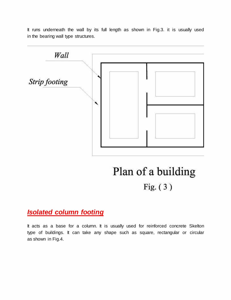
It runs underneath the wall by its full length as shown in Fig.3. it is usually used
in the bearing wall type structures.
Isolated column footing
It acts as a base for a column. It is usually used for reinforced concrete Skelton
type of buildings. It can take any shape such as square, rectangular or circular
as shown in Fig.4.
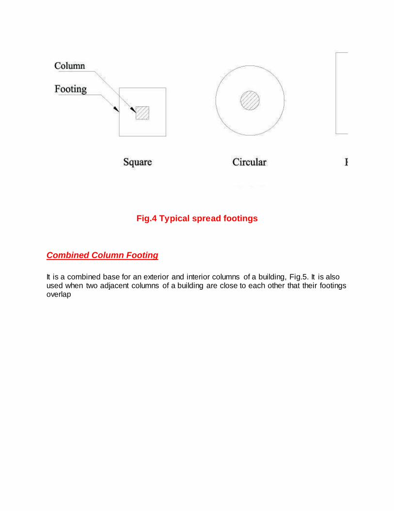
Fig.4 Typical spread footings
Combined Column Footing
It is a combined base for an exterior and interior columns of a building, Fig.5. It is also used when two adjacent columns of a building are close to each other that their footings overlap
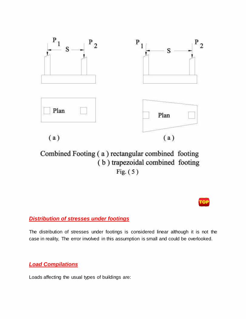
Distribution of stresses under footings
The distribution of stresses under footings is considered linear although it is not the
case in reality, The error involved in this assumption is small and could be overlooked.
Load Compilations
Loads affecting the usual types of buildings are:

1. Dead Load (D.L)
2. Live Load (L.L)
3. Wind Load (W.L)
4. Earthquake Load (E.L)
Dead Load
The full dead load acting on the elements of the structures should be considered in the
design.
Live Load
It is not probable that the full intensity of the live load will be acting at the same
time on all the floors of a multi-storey building. Consequently, the codes of
practice allow a certain reduction in the intensity of live load. According to the
Egyptian Code of practice the following reduction in live load is allowed:
No. of floors Reduction in live load %
Ground floor zero %
1st floor zero %
2nd floor 10.0 %
3rd floor 20.0 %
4th floor 30.0 %
5th floor and above 40.0 %
The live load should not be reduced for ware houses and public buildings such
as schools, cinemas, and hospitals.
Wind and Earthquake Loads
When the buildings are high and narrow the wind pressure and the earthquake
load must be taken into consideration.
Assumption used in the Design of Spread Footings
Theory of elasticity analysis indicates that the stress distribution beneath
footings, symmetrically loaded, is not uniform. The actual stress distribution
depends on the type of material beneath the footing and the rigidity of the
footing. For footings on loose cohesion-less material, the soil grains tend to
displace laterally at the edges from under the load, whereas in the center the
soil is relatively confined. This results in a pressure diagram somewhat as
indicated in Fig.6. For the general case of rigid footings on cohesive and
cohesion-less materials, Fig.6 indicates the probable theoretical pressure
distribution. The high edge pressure may be explained by considering that
edge shear must take place before settlement can take place.
Because the pressure intensities beneath the footing depend on the rigidity of the footing, the soil type and the condition of the soil, the problem is generally
indeterminate. It is common practice to use a linear pressure distribution beneath the footings and this procedure will be followed in this text. In any case little difference in
design results by using a linear pressure distribution

Allowable Bearing Stresses under Footings
The factor of safety in the calculating of the allowable bearing capacity under the
footing should not be less than 3 if the loads considered in the design is equal to the
dead load + the reduced live load. The factor of safety should not be less than 2 when
the severest condition of loading is considered, which is, dead load + full live load +
wind load or earthquake loads.
The loads of the superstructure are usually calculated at ground level. If the net
allowable bearing pressure is given, it should be reduced by the volume of concrete
below ground surface per unit area of the footing multiplied by the difference between
the unit weight of concrete and soil. If we assume equal to the average density of soil
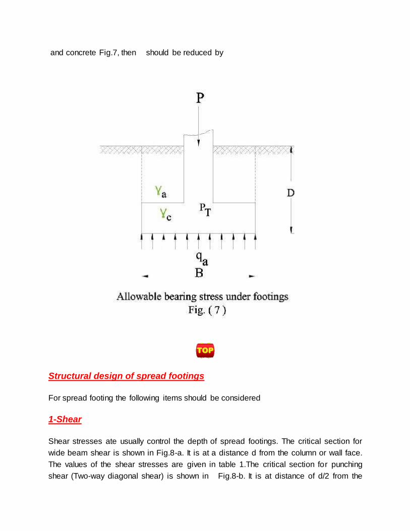
and concrete Fig.7, then should be reduced by
Structural design of spread footings
For spread footing the following items should be considered
1-Shear
Shear stresses ate usually control the depth of spread footings. The critical section for
wide beam shear is shown in Fig.8-a. It is at a distance d from the column or wall face.
The values of the shear stresses are given in table 1.The critical section for punching
shear (Two-way diagonal shear) is shown in Fig.8-b. It is at distance of d/2 from the

face of the column. This assumption is according to the American Concrete Institute
(A.CI) Code.
Table(1): allowable stresses in concrete and reinforcement:-
Types of stresses symbol Allowable stresses in
kg/cm2
Cube strength fcu 180 200 250 300
Axial comp. fco 45 50 60 70
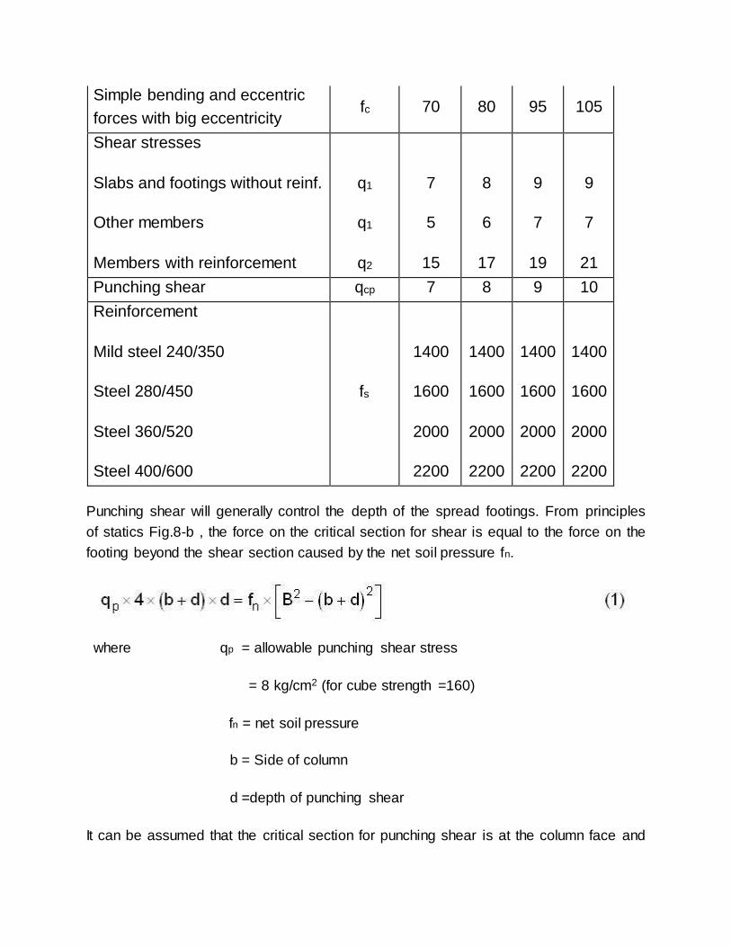
Simple bending and eccentric
forces with big eccentricity fc 70 80 95 105
Shear stresses
Slabs and footings without reinf.
Other members
Members with reinforcement
q1
q1
q2
7
5
15
8
6
17
9
7
19
9
7
21
Punching shear qcp 7 8 9 10
Reinforcement
Mild steel 240/350
Steel 280/450
Steel 360/520
Steel 400/600
fs
1400
1600
2000
2200
1400
1600
2000
2200
1400
1600
2000
2200
1400
1600
2000
2200
Punching shear will generally control the depth of the spread footings. From principles
of statics Fig.8-b , the force on the critical section for shear is equal to the force on the
footing beyond the shear section caused by the net soil pressure fn.
where qp = allowable punching shear stress
= 8 kg/cm2 (for cube strength =160)
fn = net soil pressure
b = Side of column
d =depth of punching shear
It can be assumed that the critical section for punching shear is at the column face and
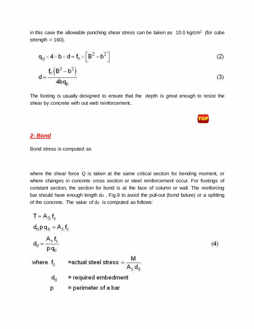
in this case the allowable punching shear stress can be taken as 10.0 kg/cm2 (for cube
strength = 160).
The footing is usually designed to ensure that the depth is great enough to resist the
shear by concrete with out web reinforcement..
2- Bond
Bond stress is computed as
where the shear force Q is taken at the same critical section for bending moment, or
where changes in concrete cross section or steel reinforcement occur. For footings of
constant section, the section for bond is at the face of column or wall. The reinforcing
bar should have enough length dd , Fig.9 to avoid the pull-out (bond failure) or a splitting
of the concrete. The value of dd is computed as follows:

For the first computation take fs equal to allowable working stress. If the calculated
dd is larger than the available dd then recalculate dd by taking fs equal to the
actual steel stress.
The allowable values of bond stress qb are as follows
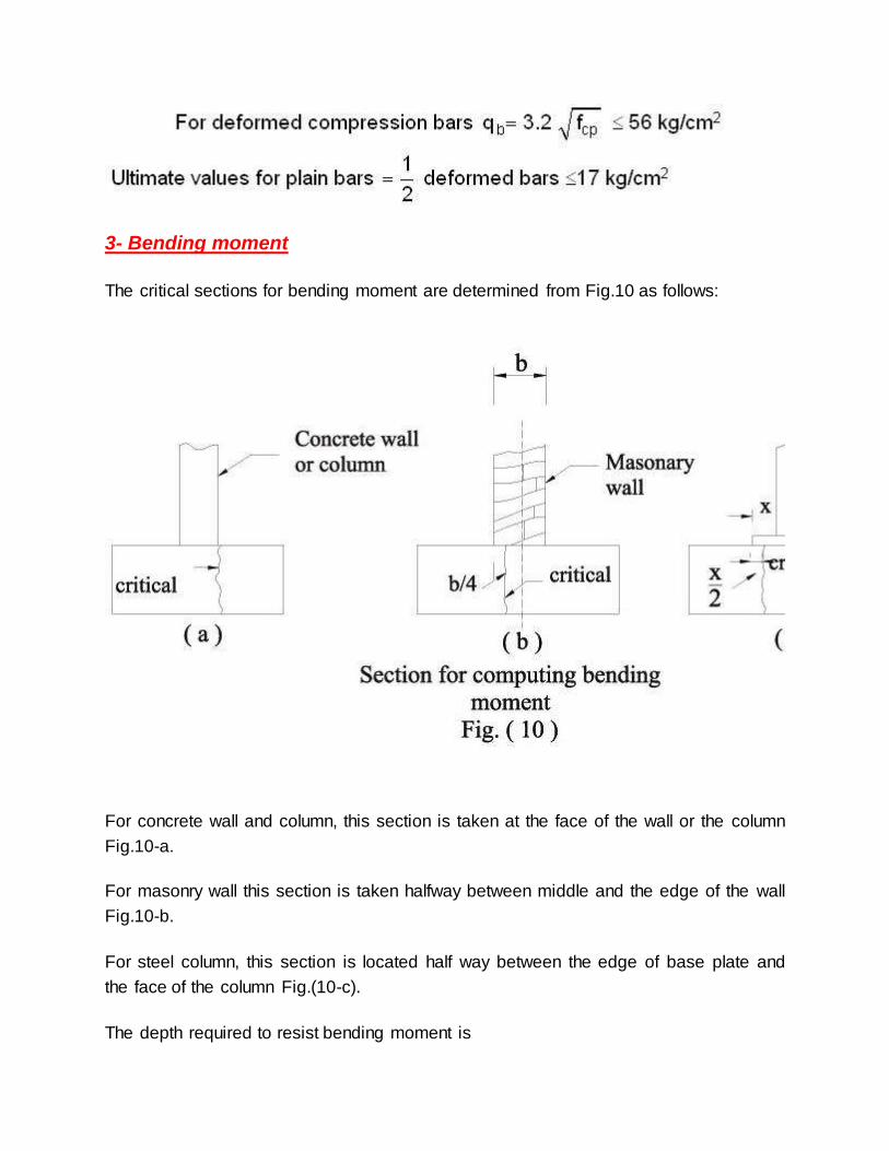
3- Bending moment
The critical sections for bending moment are determined from Fig.10 as follows:
For concrete wall and column, this section is taken at the face of the wall or the column
Fig.10-a.
For masonry wall this section is taken halfway between middle and the edge of the wall
Fig.10-b.
For steel column, this section is located half way between the edge of base plate and
the face of the column Fig.(10-c).
The depth required to resist bending moment is

4- Bearing on top of
footing
When a reinforced concrete column transmits its load to the footing, the steel of the
column, which is carrying a portion of the load, cannot be terminated on top of footing
since this may overstress the concrete in column contact area. Therefore it is necessary
to transmit the portion of load carried by the column steel by bond stress into the footing
by either extending the column steel or by dowels. From Fig.11:
where fs is the actual steel stress

5- Plain Concrete Footing Beneath R.C. Footing
It is common practice to place a plain concrete layer beneath the reinforced concrete
footing. This layer is about 20 cm. to 40 cm. The projection C of the plain concrete layer
depends on its thickness t. Referring to Fig.12 , the maximum bending moment per unit
length at section a-a is given by
Where fn = the net soil pressure.
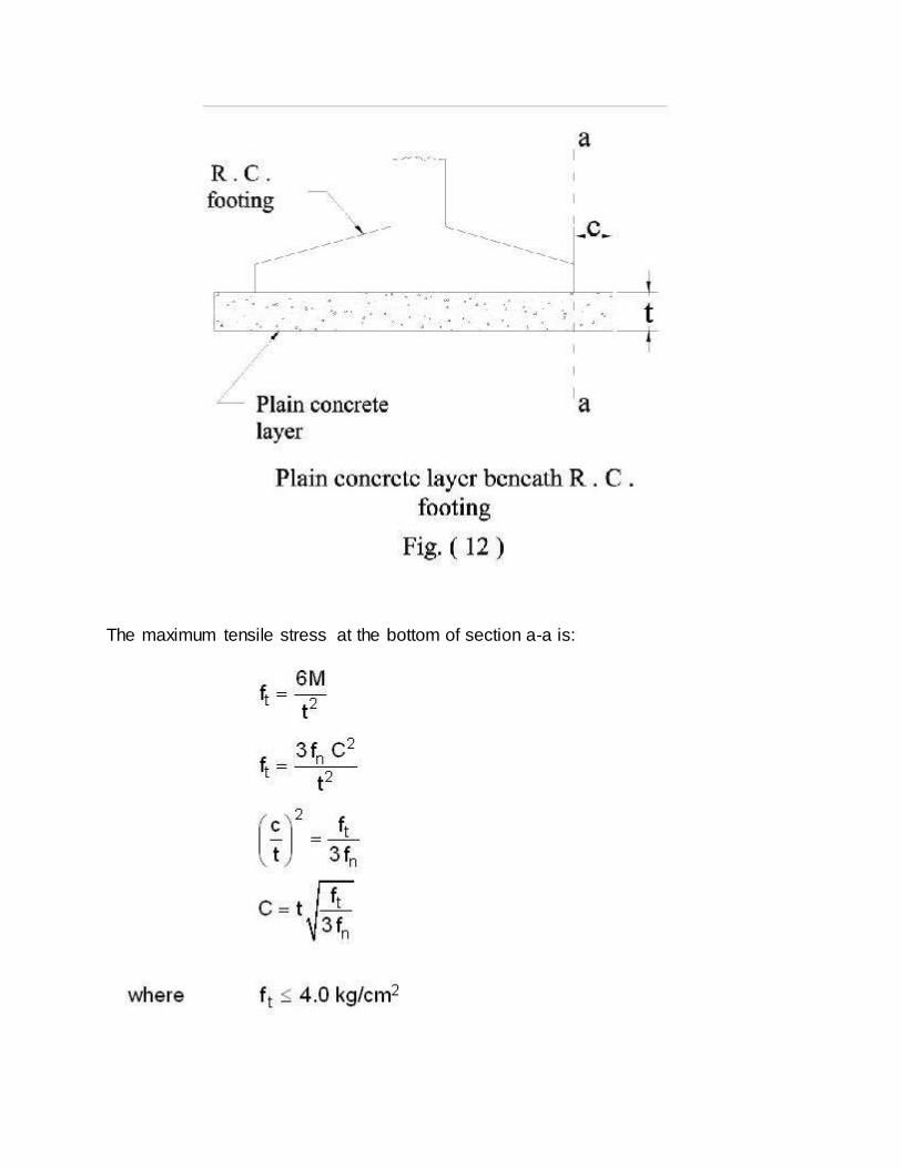
The maximum tensile stress at the bottom of section a-a is:
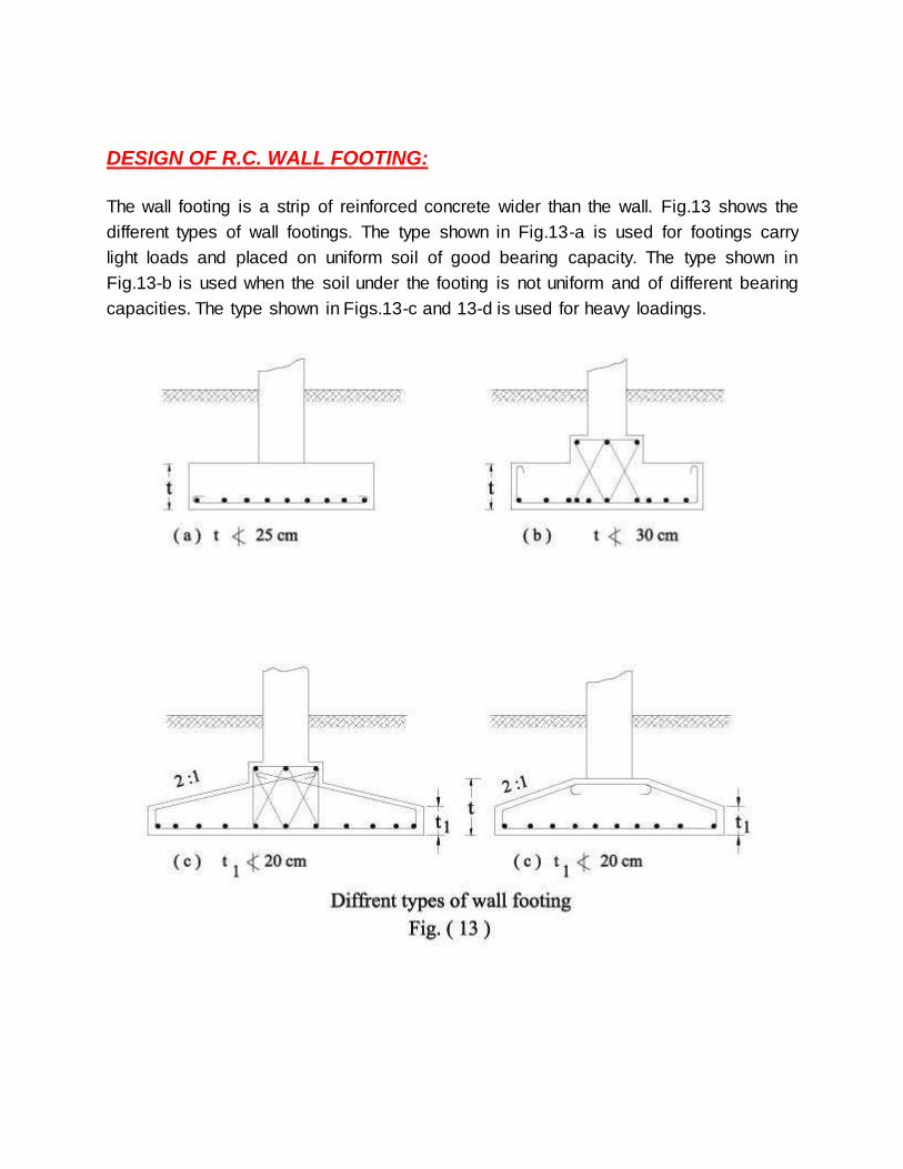
DESIGN OF R.C. WALL FOOTING:
The wall footing is a strip of reinforced concrete wider than the wall. Fig.13 shows the
different types of wall footings. The type shown in Fig.13-a is used for footings carry
light loads and placed on uniform soil of good bearing capacity. The type shown in
Fig.13-b is used when the soil under the footing is not uniform and of different bearing
capacities. The type shown in Figs.13-c and 13-d is used for heavy loadings.
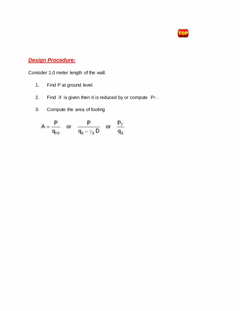
Design Procedure:
Consider 1.0 meter length of the wall.
1. Find P at ground level.
2. Find if is given then it is reduced by or compute PT .
3. Compute the area of footing
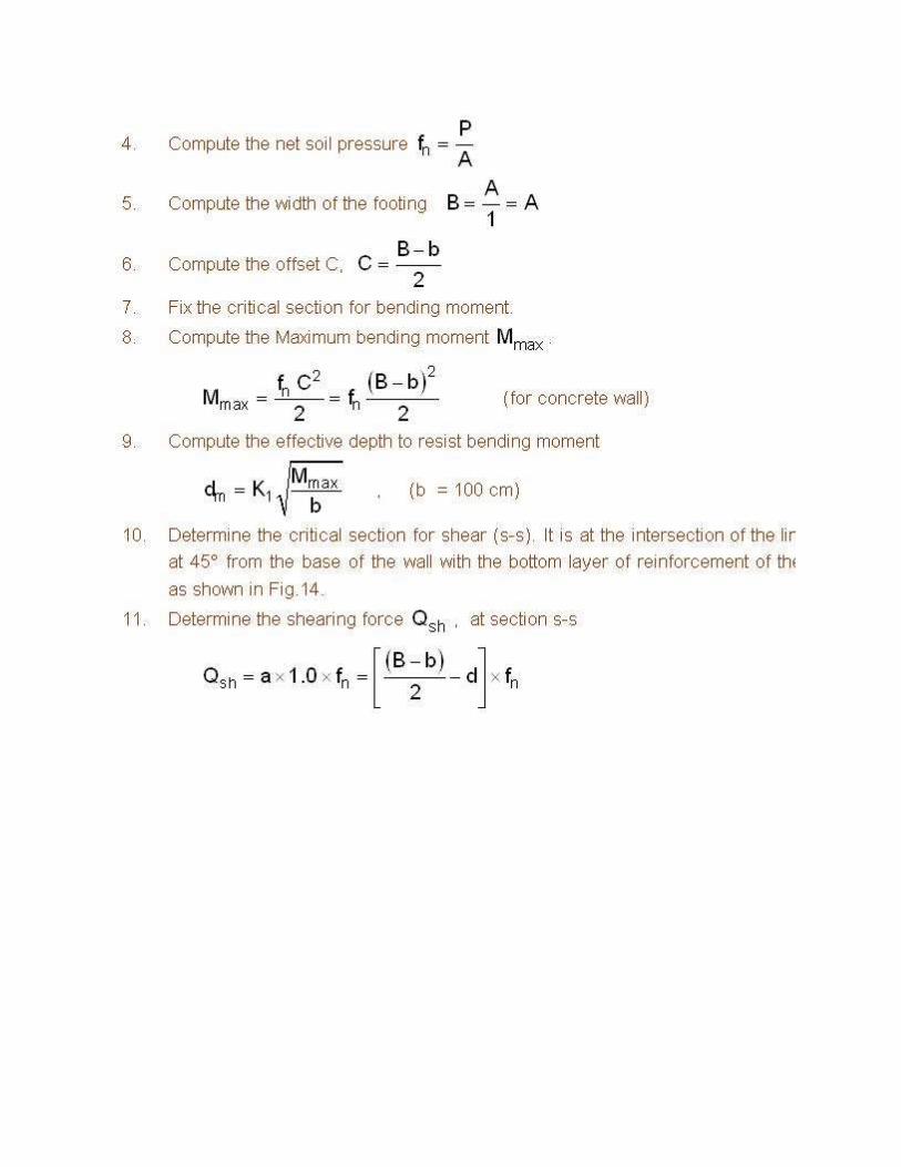
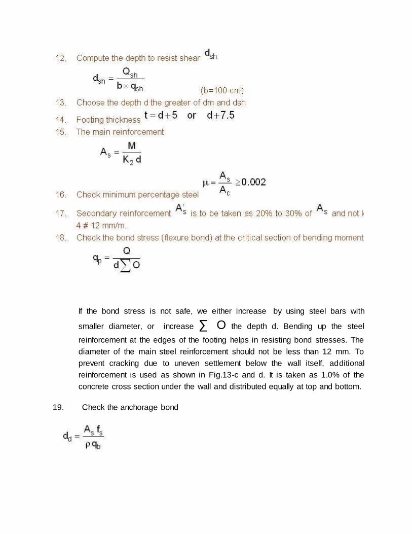
If the bond stress is not safe, we either increase by using steel bars with
smaller diameter, or increase ∑ O the depth d. Bending up the steel
reinforcement at the edges of the footing helps in resisting bond stresses. The
diameter of the main steel reinforcement should not be less than 12 mm. To
prevent cracking due to uneven settlement below the wall itself, additional
reinforcement is used as shown in Fig.13-c and d. It is taken as 1.0% of the
concrete cross section under the wall and distributed equally at top and bottom.
19. Check the anchorage bond

Design of Single Column Footing
The single column footings are usually square in plan, Rectangular footings are used if
there restriction in one direction or If the supported columns are of too elongated .rectangular cross section. In the simplest form, they consist of a single slab FIg.15-a. Fig.15-b shows a pedestaled column footing, the pedestal provides depth for a more
favorable transfer of load and in many cases is
required in order to provide the necessary length for dowels. Sloped footings such as those in Fig.15-c

Design Procedure for Square Column Footing
American Codes of Practice is equal to the moment about the critical section y-y of the net
stress acting on the hatched .area abcd Fig. 16-a. According to the Continental Codes of
practiceMmax. is equal to either; the moment of the net stresses acting on the hatched

area abgh, shown in Fig.16-b, about the critical section y-y or 0.85 the moment of the net
stresses acting on the area abcd in Fig.16-a about y-y.
8. Determine the depth required to resist punching dp.
9. Calculate dm, the depth to resist
b = B, the side of the footing according to the American Codes of Practice
b = (bc + 20) cm where bc is the side of the column according to the
Continental Codes of Practice.
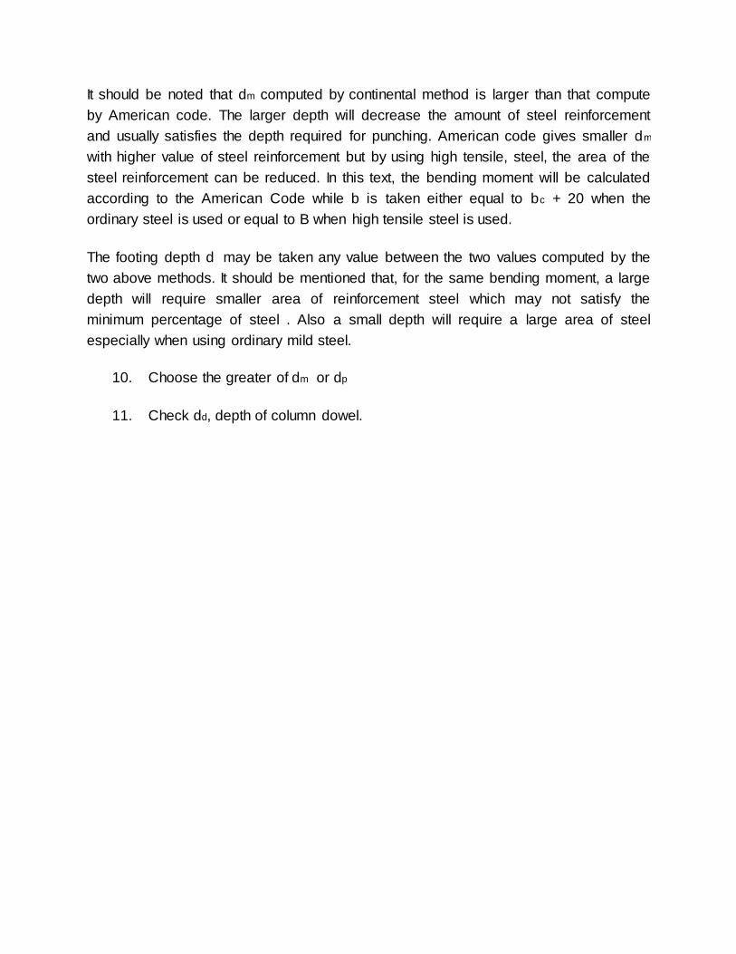
It should be noted that dm computed by continental method is larger than that compute
by American code. The larger depth will decrease the amount of steel reinforcement
and usually satisfies the depth required for punching. American code gives smaller dm
with higher value of steel reinforcement but by using high tensile, steel, the area of the
steel reinforcement can be reduced. In this text, the bending moment will be calculated
according to the American Code while b is taken either equal to bc + 20 when the
ordinary steel is used or equal to B when high tensile steel is used.
The footing depth d may be taken any value between the two values computed by the
two above methods. It should be mentioned that, for the same bending moment, a large
depth will require smaller area of reinforcement steel which may not satisfy the
minimum percentage of steel . Also a small depth will require a large area of steel
especially when using ordinary mild steel.
10. Choose the greater of dm or dp
11. Check dd, depth of column dowel.

Design Procedure for Rectangular Footing
The procedure is the same as square footing. The depth is usually controlled by
punching shear except If the ratio of length to width is large, the wide beam shear may
control the depth. The critical sections for shear are at distance d from both sides of the
column Fig.17-a. The bending moment is calculated for both directions, about 1-1 axis
and about b-b axis as shown in Fig.17.b and c.

The reinforcement in the long direction (Side L) is calculated from the bending moment ,
and is uniformly distributed over the width B. The reinforcement in the short direction
(Side B) is calculated from the bending moment M11. In locating the bars in the short
direction one has to consider that the support provided to the footing by the column is
concentrated near the middle, consequently the area of footing adjacent to the column
is more effective in resisting bending. For this reason an adjustment of steel in the short
direction is made. This adjustment place a percentage of the steel in a zone centered
on the column with a width equal to the length of the short direction of the footing. The
remainder of the reinforcement shall be uniformly distributed in two end zones, Fig.18.
According to the American Concrete Institute, the percentage of steel in the central
zone is given by:

where S = ratio of long side to short side, L/B .
SEMELLES
Single footings should be tied together by beams known as semelles as shown in
Fig.19.a. Their function is to carry the ground floor walls and transfer their loads to the
footings. Semelles can prevent relative settlement if they are of very stiff section and

heavily reinforced.
The semelle is designed as continuous reinforced concrete rectangular beam carrying the weight of the wall. The width of the semelle is equal to the width of the wall plus 5 cm and it should not be less than 25 cm. It should resist the shearing forces and
bending moments to which it is subjected, semelles must
be reinforced at top and bottom to counteract the differential settlements. by the equal
reinforcement As.
The top level of the semelle should be 20 cm below the level of the platform surrounding the building. If the level of the ground floor is higher than that of the platform, the level of the inner semmelle can be taken 20 cm below the ground floor level

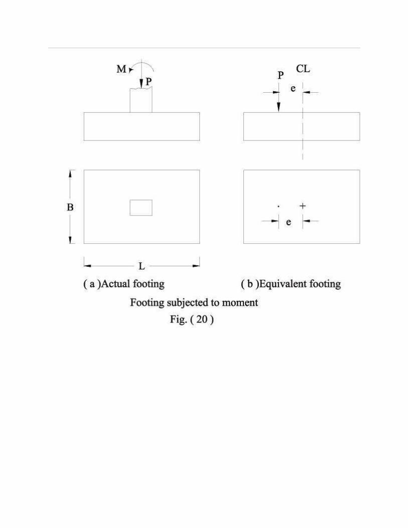
Footings subjected to Moment
Introduction
Many foundations resist, in addition to the concentric vertical load, a moment
about one or both axis of the footing. The moment may result from a load applied off
the centre of the footing . Examples of foundations that must resist moment are those
for retaining walls, abutments , bridge piers, and the columns of the foundations of tall
buildings where wind pressure causes appreciable bending moments at the base of

columns.
The soil-pressure resultant under eccentrically loaded footing is assumed to
coincide with the axial load P, but not with the centroid of the footing, which results in a
linear non-uniform pressure distribution. The maximum pressure must not exceed the
maximum allowable pressure on the soil. Tilting of the footing due to the higher intensity
of soil pressure at the toe is possible to occur . This can be reduced by using a large
safety factor when computing the allowable soil pressure. Chapter 1, Section "Footings
with Eccentric or Inclined Loads" provide for a reduction in allowable soil pressure for
eccentrically loaded footings.
Footings with Moments or Eccentricity about One Axis

where P = vertical load or resultant force
e = eccentricity of vertical load or resultant force
q = intensity of soil pressure (+ = compression)
and should not be greater than the allowable
soil pressure qa
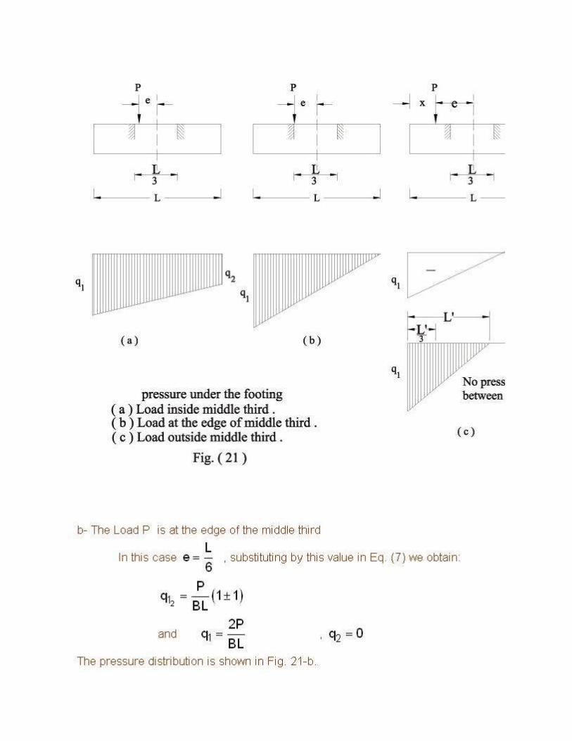
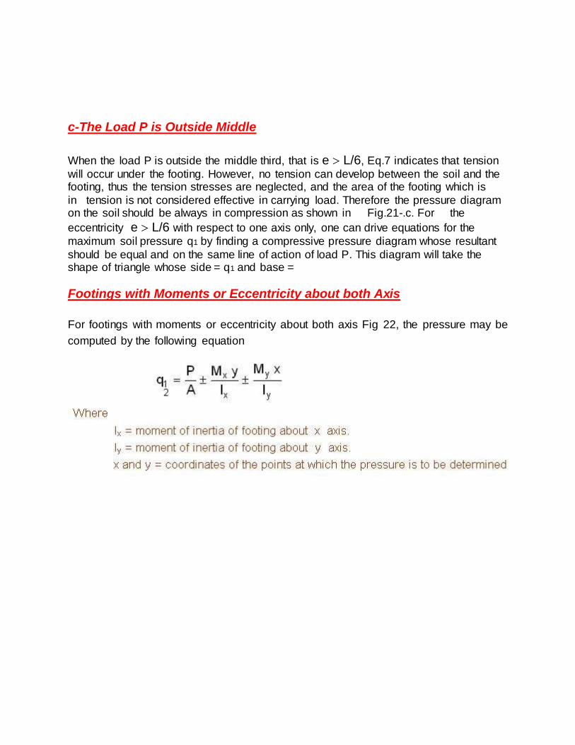
c-The Load P is Outside Middle
When the load P is outside the middle third, that is e L/6, Eq.7 indicates that tension
will occur under the footing. However, no tension can develop between the soil and the footing, thus the tension stresses are neglected, and the area of the footing which is
in tension is not considered effective in carrying load. Therefore the pressure diagram on the soil should be always in compression as shown in Fig.21-.c. For the
eccentricity e L/6 with respect to one axis only, one can drive equations for the
maximum soil pressure q1 by finding a compressive pressure diagram whose resultant
should be equal and on the same line of action of load P. This diagram will take the shape of triangle whose side = q1 and base =
Footings with Moments or Eccentricity about both Axis
For footings with moments or eccentricity about both axis Fig 22, the pressure may be
computed by the following equation

a- The Neutral Axis Outside the Base :
If the neutral axis is outside the base, then all the pressure q is in compression
and equation (9) is valid. The location of the maximum and minimum pressures on soil
may be determined readly by observing the directions of the moments. The maximum
pressure q1 is at point (1)
Fig.22-a and the minimum pressure q2 is at point (3). The pressure q1 and q2 are
determined from Eq.(9).
b- The Neutral Axis Cuts the Base
If the neutral axis cuts the base, then a certain area of the base is subjected to
tension Fig.22. As the soil is not likely to grip the footing to hold it in place , therefore the
diagram shown in Fig.22-b and Eq.(9) cannot be used. The computation of the
maximum pressure on soil must be based on the area actually in compression. The
compressive diagram is to be found in such a way that its resultant should be equal and
on the same line of action of the force P. The simplest way to get this diagram is by trial
and error as follows:
1- Find soil pressure at all corners by applying Eq.(9).
2- Determine the position of the neutral axis N-A (the line of zero pressure). This is
not a straight line, but for the problem it is assumed to be . Therefore it is only
necessary to find two points, one on each adjacent side of the footing.
3- Select another neutral axis (N'-A') parallel to (N-A) but somewhat closer to the
location of the resultant load P acting on the footing.
4- Compute the moment of inertia of the area in compression with respect to the
N'-A' . The simplest procedure is to draw the footing to scale and divide the area into rectangles and triangles
4.4 STRUCTURAL DESIGN OF FOOTINGS SUBJECTED TO MOMENT
The principle problem in the design of eccentrically loaded footings is the determination
of the pressures distribution under the footings. Once they have been determined, the
design procedure will be similar to the concentrically loaded footings, the critical
sections are selected and computations of the stresses due to moment and shear are
made.
Where the bending moments on a column come from any direction, for example from wind loads, a square footing-; is preferable unless the space restrictions dictate the choice of rectangular footing. If the bending moments always act in the same direction,
as in columns supporting rigid framed structures, the footing can be lengthed in the

direction of the eccentricity
The dimensions of the footing B and L are proportioned in such a way that the
maximum pressure at the toe does not exceed the allowable soil pressure .
If a column carries a permanent bending moment, for example a bracket carrying a
sustained load, it may be advantage to place the column off centre on the footing so that the eccentricity of the resultant loading is zero In this case the distribution of the
pressure on the base will be uniform. The long toe section of the footing should be designed as a cantilever about a section through the face of the column, Calculation of the depth to resist punching shear and wide beam shear is the same as in footings
support concentric loads
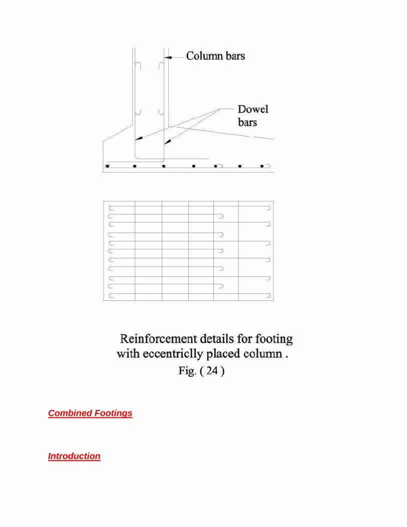
Since the bending moment at the base of the column is likely to be large for this type of
footing, the column reinforcement should be properly tied into the footing.,
Reinforcement details for this type of footings are shown in Fig.24.
For square footing it is generally most convenient to keep bar diameter and spacing the
same in both directions in order to avoid confusion in steel fixing.
Combined Footings
Introduction

The preceding section presented elements of the design of spread and wall footings. This
section considers some of the more complicated shallow-foundation problems. Among
these are footings supporting more than one column in a line (combined footings), which
may be rectangular or trapezoidal in shape, or two pads connected by a beam, as for a
strap footing. Eccentrically loaded footings and un-symmetrically shaped footings will also
be considered.
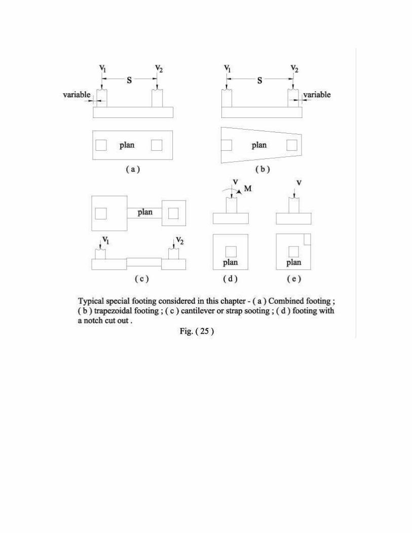
Rectangular Combined Footings
When property lines, equipment locations, column spacing, or other considerations limit
the footing clearance at the column locations, a possible solution is the use of a
rectangular-shaped footing. This type of footing may support two columns, as illustrated in
Fig.25 and 26, or more than two columns with only slight modification of the design
procedure. These footings are commonly designed by assuming a linear stress
distribution on the bottom of the footing, and if the resultant of the soil pressure coincides
with the resultant of the loads (and center of gravity of the footing), the soil pressure is
assumed to be uniformly distributed, The linear pressure distribution implies a rigid footing
on a homogeneous soil. The actual footing is generally not rigid, nor is the pressure
uniform beneath it, but it has been found that solutions using this concept are adequate.
This concept also results in a rather conservative design.

The design of a rigid rectangular footing consists in determining the location of the center of gravity (cg) of the column loads and using length and width dimensions such that the
centroid of the footing and the center of gravity of the column loads coincide. With the dimensions of the footing established, a shear
and moment diagram can be prepared, the depth selected for shear (again it is
conventional to make the depth adequate for shear without using shear reinforcement to
satisfy rigidity requirements implicitly), and reinforcing steel selected for bending
requirements. Critical sections for shear, both diagonal-tension and wide-beam, should
be taken as indicated in the previous section. The maximum positive and negative
moments are used to design the reinforcing steel and will result in steel in both bottom
and top of the beam.
In the short direction, obviously, the entire length is not going to be effective in resisting bending. That zone closest to the column will be most effective for bending, and it is
recommended that this approach be used. This is basically what the ACI Code specifies

in Art. 15.4.4 for rectangular footings
If it is accepted that the zone which includes the columns is most effective, what should
this zone width be? Certainly, it should be something greater than the width of the
column. Probably it should be no greater than the column width plus d to 1.5d, depending
on the column location based on the author's analytical work, lack of Code guidance, and
recognizing that extra steel will "stiffen" the zone and increase the moments in this zone
and reduce the moment out of the zone. An effective width using this method is illustrated
in Fig.27 For the remainder of the footing in the short direction, the ACI Code requirement
for minimum-percentage steel (Art. 10.5 or 7.13) should be used.
In selecting dimensions for the combined footing, the length dimension is somewhat
critical if it is desired to have shear and moment diagrams mathematically close as an
error check. This means that unless the length is exactly the computed value from the
location of the cg of the columns, an eccentricity will be introduced into the footing,

resulting in a nonlinear earth-pressure diagram. The actual as-built length, however,
should be rounded to a practical length, say, to the nearest 0.25 or 0.5 ft (7.5 to 15 cm).
The column loads may be taken as concentrated loads for computing shear and moment
diagrams. For design the shear and moment .values at the edge (face) of the column
should be used. The resulting error, using this approach, is negligible.Fig.(28)

If the footing is loaded by more than two columns, the problem is still statically
determinate; the reactions (column loads) are known as well as the distributed loading,
i.e. the soil pressure.
Design Procedure of rectangular combined footing:-
Referring to Fig.29, the steps of the design can be summarized as follows :
1- Find the line of application of the resultant R. This fix L/2 since y is known and
limited. It should be indicated that unless the length L is exactly the computed
value, an eccentricity will be introduced into the footing, resulting in a nonlinear soil
pressure diagram. The actual as-built length, however, should be rounded to a
practical length, say, to the nearest 5 cm or 10cm.
maximum +ve moment at point K where the shearing force = zero
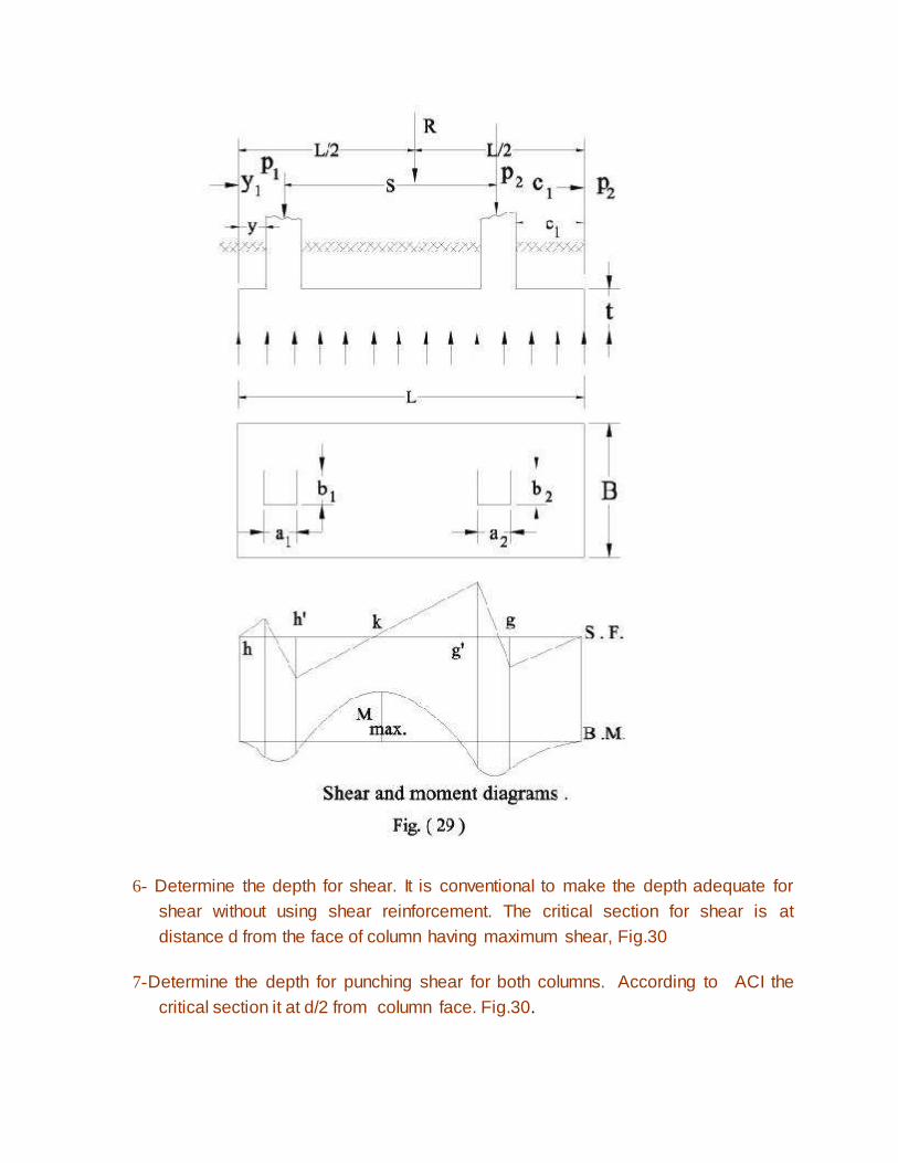
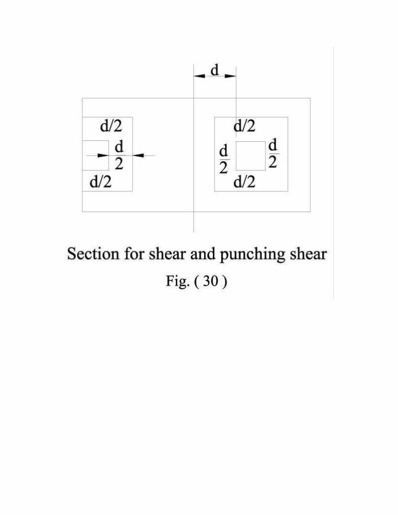
6- Determine the depth for shear. It is conventional to make the depth adequate for
shear without using shear reinforcement. The critical section for shear is at
distance d from the face of column having maximum shear, Fig.30
7-Determine the depth for punching shear for both columns. According to ACI the
critical section it at d/2 from column face. Fig.30.

9-d is chosen the greatest of
t = d + 5 to 8 cm.
11- Check the bond stresses and anchorage length d.
12- Short direction :
The column loads are distributed crosswise by transverse beams (hidden), one
under each column. The length of the beams are equal to the width of the footing
B. The effective width of the transverse beam may be taken the least of the
following:
a- Column width a + 2 d or column width a + d + the projection of the footing
beyond the column y, Fig.31.
b- The width of the footing
It should be noted that ACI code consider that the effective width of the
transverse beam equal to column width a + d or column width a + d/2 + y
The Transverse bending moment MT1 at column (1) is equal to
The transverse reinforcement should be distributed over the effective width
of the transverse beam. For the remainder of the footing, minimum
percentage steel should be used. The bond stresses and anchorage length
dd, should be checked.
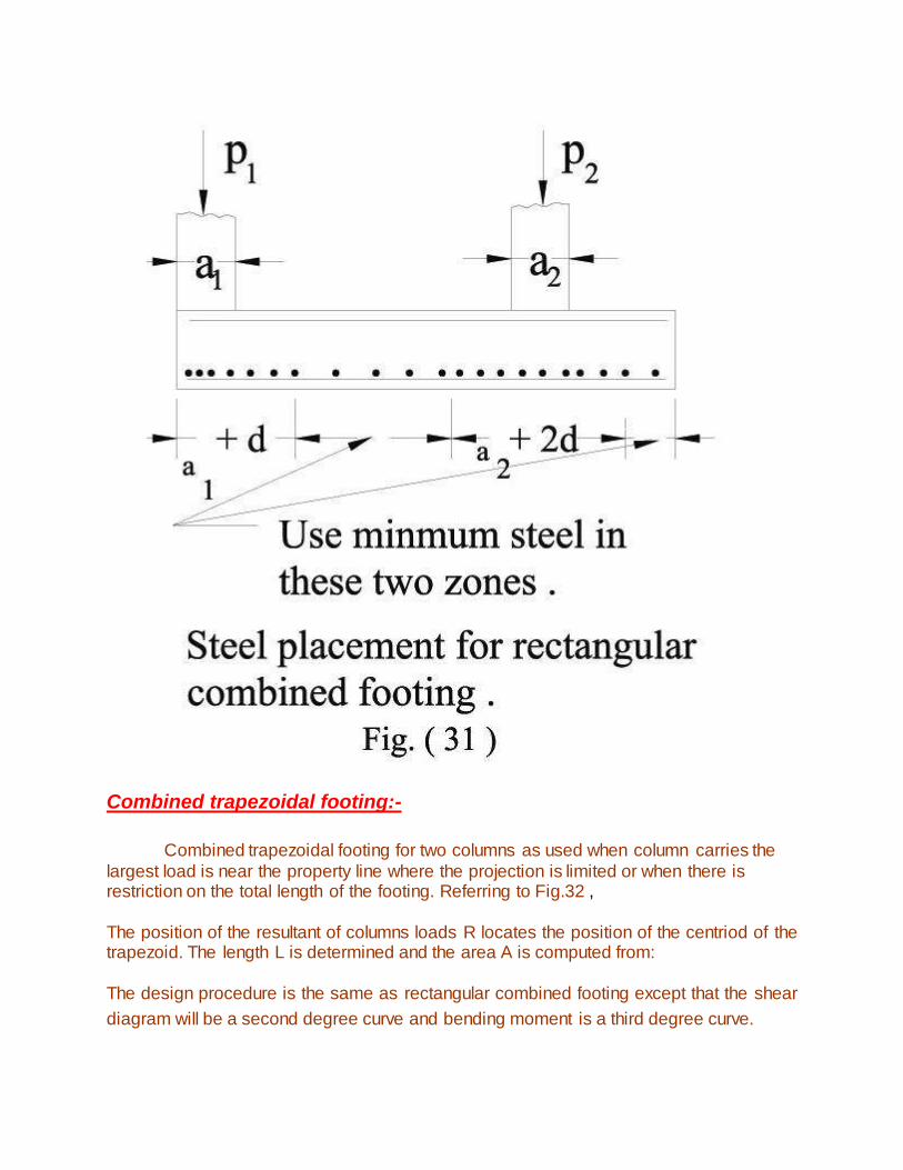
Combined trapezoidal footing:-
Combined trapezoidal footing for two columns as used when column carries the
largest load is near the property line where the projection is limited or when there is restriction on the total length of the footing. Referring to Fig.32 ,
The position of the resultant of columns loads R locates the position of the centriod of the trapezoid. The length L is determined and the area A is computed from:
The design procedure is the same as rectangular combined footing except that the shear
diagram will be a second degree curve and bending moment is a third degree curve.

Design of Strap or Cantilever Footings
A strap footing may be used where the distance between columns is so great that a
combined or trapezoid footing becomes quite narrow, with resulting high bending
moments, or where as in previous section.
A strap footing consists in two column footings connected by a member termed a strap, beam, or cantilever which transmits the moment from the exterior footing. Fig.33 illustrates a strap footing. Since the strap is designed for
moment, either it should be formed out of contact with the soil or the soil should be
loosened for several inches beneath the strap so that the strap has no soil pressure
acting on it. For simplicity of analysis, if the strap is. not very long, the, weight of the
strap may be neglected.
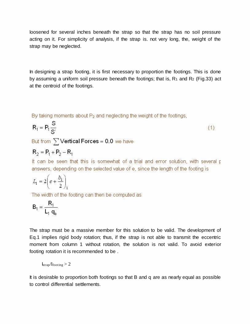
In designing a strap footing, it is first necessary to proportion the footings. This is done
by assuming a uniform soil pressure beneath the footings; that is, R1 and R2 (Fig.33) act
at the centroid of the footings.
The strap must be a massive member for this solution to be valid. The development of
Eq.1 implies rigid body rotation; thus, if the strap is not able to transmit the eccentric
moment from column 1 without rotation, the solution is not valid. To avoid exterior
footing rotation it is recommended to be .
Istrap/Ifooting > 2
It is desirable to proportion both footings so that B and q are as nearly equal as possible
to control differential settlements.

Design Procedure for Strap Footing
reaction under the interior footing will be decreased by the same value, referring to
Fig.33
1- The design begins with trial value of e
6- Check that the centroid of the areas of the two footings coincide with the
resultant of column loads.
7- Calculate the moments and shear at various parts of the strap footing.
8- Design of the strap
The strap represents a single-span beam loaded upward by the loads transferred
to it by the two footings and supported by downward reactions at the centre lines
of the two columns. Thus the upward load over the length L is equal to R1/L t/m'.
The location of the maximum moment is obtained by equating the shear force to
zero. The moment decreases toward the interior column and is zero at the center

line of that column. Hence half the strap reinforcement is discontinued where no
longer needed and the other half is continued through the interior column. Check
shear stresses and use stirrups, and bent bars if necessary.
9- Design of the exterior footing
The exterior footing acts exactly like a wall footing of a length equal to L. Even
though the column is located at the edge the balancing action of the strap is such
as to transmit the reaction R1 uniformly over the length L1 thus resulting in the
desired uniform soil pressure. The design is carried out exactly as for a wall
footing.
10- Design of the interior footing
The interior footing may be designed as a simple single column footing. The main
difference is that the punching shear should be checked along the perimeter fghj,
Fig.33.

RAFT FOUNDATIONS
Introduction
The raft foundation is continuous footing that cover the entire area beneath a structure
and supports all the walls and columns. The term mat is also used for foundation of this
type. It is used generally on soil of low bearing capacity and where the area covered by
spread footings is more than half the area covered by the structure. Raft foundation is
also used where the soil mass contains compressible lenses or the soil is sufficiently
erratic so that differential settlement would be difficult to control. The raft tends to bridge
over erratic deposits and reduces the differential settlement.
Bearing Capacity of Rafts on Sand
Beating capacity of foundations on sand increases as the width increases. Owing to the
big width of raft compared to the width of an ordinary footing, the allowable bearing
capacity under the raft will be much greater than that of the footing.
It was noticed in practice that using an allowable bearing capacity under the raft equal
to twice the allowable bearing capacity determined for an ordinary footing. resting on
the same sand will give a reasonable and acceptable amount of settlement.
If the water table lies at a depth equal to or greater than B, the width of the raft, the
allowable bearing capacity, determined for dry condition, should not be reduced. If there
is a possibility that the water table rises up till it floods the site, the allowable bearing
capacity should be reduced by 50%. If the water table is at a depth intermediate between
B and the base of the raft, an appropriate reduction between zero and 50% should be
made.
Bearing Capacity of Rafts on Clay.
In clays, the bearing capacity is not affected with the width of the foundation Therefore,
the bearing capacity under a raft will be the same as that under an ordinary footing.
If the estimated differential settlement under the raft is more than tolerable or if the
weight of the building divided by its area gives a bearing stress greater than the
allowable bearing capacity, floating or partially floating foundation should be considered.
To execute a floating foundation, excavation is to be carried out till a depth D is reached

where the weight of the excavated soil equals to the weight of the structure, figure 2. In
this case, the excess superimposed stress Δp at foundation level equals to zero and
consequently, the building will suffer no settlement.
If the full weight of the building =Q
and the weight of soil removed =Ws
and the excess load at foundation level =Qe
Qe=QWs
In case of floating foundation ;
Q = Ws and therefore Qe = Zero
In case of partially floating foundation, Qe has a certain value which when divided by
foundation area gives the allowable bearing capacity of the soil ;
Design of Raft Foundations ;
Rafts may be designed as rigid structures (so called conventional analysis) whereby soil
pressure acting against the raft slab is assumed uniformly distributed and equal to the
total weight of the building divided by the area of the raft. This is correct i f the columns
are more or less equally loaded and equally spaced, but it is difficult to fulfill this
requirement in practice so it is allowed that the column loads and spacings to be varied
within 20%. However if the downward loads on some areas are much heavier than on
others, it is advisable to divide the raft into different areas and design each area on its
corresponding average pressure. Continuity of the slab between such areas is
commonly provided, although for the areas of great differences in pressure it is
advisable to construct vertical construction joint through the slab and the superstructure
to allow for differential settlement.
In flexible raft foundation the design cannot be based only on the strength requirements

but it is necessary to be subjected due to the predicted settlement. The thickness and
the amount of reinforcement of the raft should be selected in a such way to prevent
development of cracks in the slab. As the differential settlement is not considered in the
structural design it is customary to reinforce the raft with twice its theoretical amount of
reinforcement. The quantity of the steel may be taken as 1% of the cross sectional area
divided at top and bottom. The thickness of the slab should not be greater than 0.01 of
the radius of curvature. The thickness may be .increased near columns to prevent shear
failure.
There are two types of raft foundations:
1- Flat slab raft which is an inverted flat slab Fig.34-a. If the thickness of the slab is
not enough to resist punching shear under columns, pedestals may be .used
above the slab Fig.34-.b or, below the .slab, by thickening the flat slab under the
columns as shown in Fig.34-c.
2- Slab and girder raft which, is. an inverted R.C. floor, composed of slabs and
beams extending along column, rows in both directions, Fig.34-d, it is also,
termed ribbed mat. If a continuous floor is desired in the basement, the ribs
(beams) may be placed beneath the slab,Fig.34-e.

Design of Flat Slab Raft
The raft, which is of uniform thickness, is divided into column strips and middle strips as
shown in Fig.35-a. The width of column strip is equal to b + 2d, where b = column side.
The depth of the raft d may assumed approximately equal to 1/10 the clear span
between columns. Also, the width of column strip may be taken equal to 3 b.
The column strips are design as continuous beams loaded with triangular loads as
shown, in Fig.35-b. The net intensity of the uniform upward pressure fn under any area,
for example the area DEFG may be assumed equal to one fourth of the total loads on
the columns at D,E,F and G divided by the area DEFG.

The total loads acting upon the column strip BDEQ, Fig.35-a are assumed as triangular
loading diagrams shown in Fig.35-b. The total load on part DE, PDE, is assumed to be
the net pressure acting upon the area DHEJ.
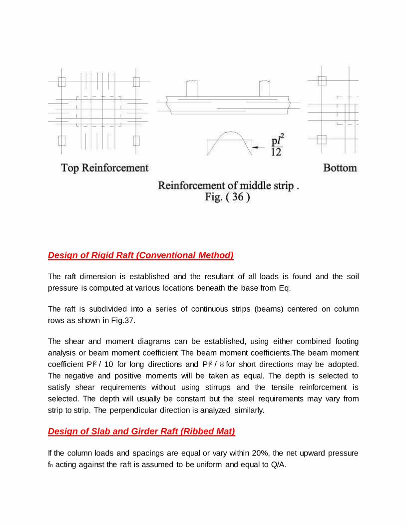
Design of Rigid Raft (Conventional Method)
The raft dimension is established and the resultant of all loads is found and the soil
pressure is computed at various locations beneath the base from Eq.
The raft is subdivided into a series of continuous strips (beams) centered on column
rows as shown in Fig.37.
The shear and moment diagrams can be established, using either combined footing
analysis or beam moment coefficient The beam moment coefficients.The beam moment
coefficient PI2 / 10 for long directions and PI2 / 8 for short directions may be adopted.
The negative and positive moments will be taken as equal. The depth is selected to
satisfy shear requirements without using stirrups and the tensile reinforcement is
selected. The depth will usually be constant but the steel requirements may vary from
strip to strip. The perpendicular direction is analyzed similarly.
Design of Slab and Girder Raft (Ribbed Mat)
If the column loads and spacings are equal or vary within 20%, the net upward pressure
fn acting against the raft is assumed to be uniform and equal to Q/A.

where
Q = weight of building at ground level, and
A = area of raft (along the outside of the exterior columns).
If this pressure is greater than the net allowable soil pressure, the area of the raft should
be increased to an area large enough to reduce the uniform pressure to the net
allowable value. This can be achieved by projecting the slab beyond the outside face of
exterior columns.
Referring to Fig. 38 , the various elements of the raft can be designed as follows:
Design of slab:
1-Design of transverse beams B1 and B2
The uniform distributed load/m' on
Let R1 and R2 be the central reaction of beams B1 and B2 on the central main beam B3
respectively. The end beams B1 carries only part of the load carried by the beam B2
and hence the central reaction R1 is assumed to be equal to
KR2 where K is a factor based on comparative area, then
Also it is assumed that the sum of the central reactions from the transverse beams B1
and B2 is equals to the total loads from central columns, thus
2R1+8R2 =2P1 + 2 P2 (2)
Solving Eqs. (1) and (2), R1 and R2 can be determined.
The bending moment and shearing force diagrams can be drawn as shown
in Fig.39. The reactions R1 and R2 can be determined by equating the sum of
vertical forces to zero. The central section of the beams at positive bending moment can
be designed as T-beam as the slab is on the compression side. The sections of the
beams below central beam B3 is to be designed as rectangular section.
2- Design of central main beam B3
The loading, shearing force, and bending moment diagrams are shown in Fig.40-a. The
section can be designed as T-beam.
3- Design of central main beam B4

The loading, shearing force, and bending moment diagrams are shown in Fig.40-b The
section can be designed as T-beam


![[FOUNDATION ENGINEERING] CHAPTER FOUR FOUNDATION SETTLEMENT · [FOUNDATION ENGINEERING] Assist. lecturer : Haidar Hassan Haidar CHAPTER FOUR FOUNDATION SETTLEMENT 2 4.2 Contact pressure](https://static.fdocuments.in/doc/165x107/5e7b129063d7961a2760e218/foundation-engineering-chapter-four-foundation-foundation-engineering-assist.jpg)